EP0371473A2 - Lineare Antriebsanordnung für ein Kopiergerät - Google Patents
Lineare Antriebsanordnung für ein Kopiergerät Download PDFInfo
- Publication number
- EP0371473A2 EP0371473A2 EP89121982A EP89121982A EP0371473A2 EP 0371473 A2 EP0371473 A2 EP 0371473A2 EP 89121982 A EP89121982 A EP 89121982A EP 89121982 A EP89121982 A EP 89121982A EP 0371473 A2 EP0371473 A2 EP 0371473A2
- Authority
- EP
- European Patent Office
- Prior art keywords
- optical mechanism
- linear driving
- original document
- document scanning
- linear
- Prior art date
- Legal status (The legal status is an assumption and is not a legal conclusion. Google has not performed a legal analysis and makes no representation as to the accuracy of the status listed.)
- Granted
Links
Images



Classifications
-
- G—PHYSICS
- G03—PHOTOGRAPHY; CINEMATOGRAPHY; ANALOGOUS TECHNIQUES USING WAVES OTHER THAN OPTICAL WAVES; ELECTROGRAPHY; HOLOGRAPHY
- G03B—APPARATUS OR ARRANGEMENTS FOR TAKING PHOTOGRAPHS OR FOR PROJECTING OR VIEWING THEM; APPARATUS OR ARRANGEMENTS EMPLOYING ANALOGOUS TECHNIQUES USING WAVES OTHER THAN OPTICAL WAVES; ACCESSORIES THEREFOR
- G03B27/00—Photographic printing apparatus
- G03B27/32—Projection printing apparatus, e.g. enlarger, copying camera
- G03B27/52—Details
- G03B27/522—Projection optics
- G03B27/525—Projection optics for slit exposure
- G03B27/526—Projection optics for slit exposure in which the projection optics move
- G03B27/527—Projection optics for slit exposure in which the projection optics move as a whole in a translatory movement
-
- G—PHYSICS
- G03—PHOTOGRAPHY; CINEMATOGRAPHY; ANALOGOUS TECHNIQUES USING WAVES OTHER THAN OPTICAL WAVES; ELECTROGRAPHY; HOLOGRAPHY
- G03G—ELECTROGRAPHY; ELECTROPHOTOGRAPHY; MAGNETOGRAPHY
- G03G15/00—Apparatus for electrographic processes using a charge pattern
- G03G15/04—Apparatus for electrographic processes using a charge pattern for exposing, i.e. imagewise exposure by optically projecting the original image on a photoconductive recording material
-
- G—PHYSICS
- G03—PHOTOGRAPHY; CINEMATOGRAPHY; ANALOGOUS TECHNIQUES USING WAVES OTHER THAN OPTICAL WAVES; ELECTROGRAPHY; HOLOGRAPHY
- G03G—ELECTROGRAPHY; ELECTROPHOTOGRAPHY; MAGNETOGRAPHY
- G03G15/00—Apparatus for electrographic processes using a charge pattern
- G03G15/04—Apparatus for electrographic processes using a charge pattern for exposing, i.e. imagewise exposure by optically projecting the original image on a photoconductive recording material
- G03G15/043—Apparatus for electrographic processes using a charge pattern for exposing, i.e. imagewise exposure by optically projecting the original image on a photoconductive recording material with means for controlling illumination or exposure
Definitions
- the present invention generally relates to a driving apparatus and more particularly, to a linear driving arrangement to be used in a copying apparatus or the like for alternately displacing optical mechanisms incorporated in the copying apparatus.
- a drum projection optical mechanism DP and an original document scanning optical mechanism OS are coupled to each other through a wire/pulley mechanism F including a steel wire W passed around pulleys P1, P2 and P3 and a shaft of a driving motor M, and are controlled in speed so that the speed ratio thereof becomes to be 2 to 1, while the drum projection optical mechanism DP and the original document scanning optical mechanism OS are further arranged to be displaced at predetermined speed patterns by controlling driving of the motor M connected to said wire/pulley mechanism F.
- the conventional linear driving apparatus as referred to above has such a disadvantage that, since the drum projection optical mechanism DP and the original document scanning optical mechanism OS are arranged to be connected to and restricted by the steel wire W of the wire/pulley mechanism F, when a variation arising from assembling errors, etc. takes place in an optical path length, positional adjustments for the mechanisms DP and OS can not be readily effected, and thus, a very high accuracy is required in the assembly. Similarly, even in the case where a variation with time due to expansion and contraction of the steel wire W, etc. should take place besides the variation by the assembling errors referred to above, it becomes very difficult to make adjustments for bringing an image to be copied into focus. The inconveniences as described above become a serious obstacle for the improvement in the performance of a copying apparatus.
- an essential object of the present invention is to provide a linear driving arrangement for use in a copying apparatus and the like, which is capable of readily effecting positional adjustments of a drum projection optical mechanism and an original document scanning optical mechanism employed therein.
- Another object of the present invention is to provide a linear driving arrangement of the above described type which is simple in construction and stable in functioning, and can be readily incorporated into a copying apparatus and the like at low cost.
- a linear driving arrangement for use in a copying apparatus and the like, which includes first and second linear driving sections adapted to displace a drum projection optical mechanism and an original document scanning optical mechanism from respective initial positions alternately in an original document scanning direction, a driving control section which imparts speed pattern for the drum projection optical mechanism and the original document scanning optical mechanism whose speed ratio is at 2 to 1, and also, controls said first and second linear driving sections according to the speed pattern, and an initial position adjusting section for independently controlling the respective first and second linear driving sections according to external instructions, apart from the control to be effected by said driving control section.
- the first and second linear driving sections are independently driven according to said instruction, whereby respective initial positions for the drum projection optical mechanism and the original document scanning optical mechanism are adjusted.
- the driving control section is actuated after the adjustments of the drum projection optical mechanism and the original document scanning optical mechanism have been effected, these mechanisms are displaced according to the speed pattern.
- Fig. 1 a general construction of a linear driving arrangement according to one preferred embodiment of the present invention.
- the linear motor 10 equivalent to a first linear driving section is constituted by movable members 12 and 12 respectively disposed at opposite sides of the drum projection optical mechanism 30, and stators 11 and 11 perpendicularly disposed to confront the corresponding movable members 12 and 12 as shown, and by restricting sliding movement of the movable members 12 and 12 with a rod-like guide member 50 disposed along the stator 11 at one side to extend therethrough, the drum projection optical mechanism 30 is adapted to be displaced in an original document scanning direction.
- movable members 22 are respectively disposed at opposite sides of the original document scanning optical mechanism 40, with the stators 11 and 11 and the guide member 50 extending therethrough being commonly used therefor also so as to displace said mechanism 40 in the similar manner as in the linear motor 10.
- it is so arranged to displace the drum projection optical mechanism 30 and the original document scanning optical mechanism 40 at a speed ratio of 2 to 1 by independently controlling the linear motors 10 and 20.
- encoders 13 and 23 are respectively provided on the linear motors 10 and 20 for detecting respective displaced positions of the drum projection optical mechanism 30 and the original document scanning optical mechanism 40.
- a hall effect element (not particularly shown here) is provided to detect the magnetic pole of the confronting stator 11.
- a mirror base 31 provided with a halogen lamp 311 and a reflecting mirror 312 thereon
- another mirror base 41 provided with reflecting mirrors 411 and 412 may be adopted. More strictlyover, in positions which are out of contact with the optical mechanism 30 to be displaced in the original document scanning direction, there are fixedly provided a zoom lens assembly 71, and a mirror base 72 provided with a reflecting mirror 721, etc.
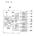
- the linear motor control circuit 60 mainly includes a micro-computer 61, i.e. so-called software servo, and is arranged to produce three-phase exciting current to be applied to the movable members 12 and 22 of the linear motors 10 and 20 so as to displace the drum projection optical mechanism 30 and the original document scanning optical mechanism 40 according to the predetermined patterns.
- a micro-computer 61 i.e. so-called software servo
- data for respective displaced positions of the drum projection optical mechanism 30 and the original document scanning optical mechanism 40 are successively introduced, through encoders 13 and 23 of the linear motors 10 and 20 connected thereto, into the microcomputer 61, where said data are compared with the speed pattern data preliminarily stored therein, and PWM (Pulse Width Modulation) signals 613 and 614 are produced according to the result of the comparison.
- PWM Pulse Width Modulation
- the PWM signals 613 and 614 are respectively applied to three-phase driver circuits 62 and 63 which are coupled with the hall effect elements 15 and 25 of the movable members 12 and 22 to receive signals therefrom, while said three-phase driver circuits 62 and 63 produce three-phase exciting current for subjecting the movable members 12 and 22 to the three-phase excitation.
- the micro-computer 61 also includes an initial position adjusting section 612 having the function for respectively adjusting the initial positions of the drum projection optical mechanism 30 and the original document scanning optical mechanism 40, in addition to a driving control section 611 having the function to control the linear motors 10 and 20.
- the linear motor 10 is represented as a motor A, while the linear motor 20 is denoted as a motor B for the convenience of explanation.
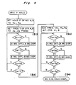
- the linear motors 10 and 20 are respectively driven until count data SA and SB of the counters A and B which give the respective displaced positions of the drum projection optical mechanism 30 and the original document scanning optical system 40, i.e. the respective displaced positions of the linear motors 10 and 20, become equal to the preliminarily set hold-position data for the linear motors 10 and 20, and thus, the optical mechanisms 30 and 40 are respectively returned to the initial positions.
- initial setting is effected so that counters A and B are respectively preset at such timing that ZA phase of the encoder 13 and ZB phase of the encoder 23 become active (Step S1).
- Step S2 After driving the linear motor 10 until ZA phase of the encoder 13 becomes active, the linear motor 20 is driven until ZB phase of the encoder 23 becomes active (Step S2).
- position adjusting data PA and PB related to the displacing amounts required for positional adjustments of the optical mechanisms 30 and 40 from the initial positions thereof are stored in a predetermined register (Step S3). It is to be noted that these position adjusting data PA and PB are arranged to be respectively set through switches or the like (not shown) connected to input ports of said micro-computer 61.
- the linear motor 10 is driven until the count data SA and the position adjusting data PA become equal to each other, and thereafter, the linear motor 20 is driven until the count data SB and the position adjusting data PB become equal to each other.
- the optical mechanisms 30 and 40 are to be respectively positionally adjusted by the displacing amounts corresponding to the position adjusting data PA and PB (Step S4).
- the concept of the present invention is not limited in its application, to the foregoing embodiment alone, but may be applied, for example, to such a modification, in which two units of wire/pulley mechanisms, etc., are employed for the first and second linear driving sections so as to independently displace the drum projecting optical mechanism and the original document scanning optical mechanism in the original document scanning direction.
- the linear driving arrangement of the present invention since it is so arranged that the first and second linear driving sections can be independently driven by external instructions, even when deviation or variation is taking place due to assembling errors or variation with time, etc., respective positional adjustments for the optical mechanisms may be readily effected for correction of the optical path length to a proper value, which is very significant for improving the performance of the copying apparatus on the whole.
Landscapes
- Physics & Mathematics (AREA)
- Optics & Photonics (AREA)
- General Physics & Mathematics (AREA)
- Optical Systems Of Projection Type Copiers (AREA)
- Exposure Or Original Feeding In Electrophotography (AREA)
Applications Claiming Priority (2)
| Application Number | Priority Date | Filing Date | Title |
|---|---|---|---|
| JP63304359A JPH02149869A (ja) | 1988-11-30 | 1988-11-30 | 複写機の直線駆動装置 |
| JP304359/88 | 1988-11-30 |
Publications (3)
| Publication Number | Publication Date |
|---|---|
| EP0371473A2 true EP0371473A2 (de) | 1990-06-06 |
| EP0371473A3 EP0371473A3 (de) | 1992-03-04 |
| EP0371473B1 EP0371473B1 (de) | 1994-07-27 |
Family
ID=17932070
Family Applications (1)
| Application Number | Title | Priority Date | Filing Date |
|---|---|---|---|
| EP89121982A Expired - Lifetime EP0371473B1 (de) | 1988-11-30 | 1989-11-29 | Lineare Antriebsanordnung für ein Kopiergerät |
Country Status (4)
| Country | Link |
|---|---|
| US (1) | US5015936A (de) |
| EP (1) | EP0371473B1 (de) |
| JP (1) | JPH02149869A (de) |
| DE (1) | DE68917095T2 (de) |
Families Citing this family (5)
| Publication number | Priority date | Publication date | Assignee | Title |
|---|---|---|---|---|
| JPH02151258A (ja) * | 1988-11-30 | 1990-06-11 | Sharp Corp | 直線駆動装置 |
| JP2573096B2 (ja) * | 1990-11-17 | 1997-01-16 | 三田工業株式会社 | 光学系駆動装置 |
| JP3302746B2 (ja) * | 1992-12-18 | 2002-07-15 | 株式会社リコー | 走行体駆動装置 |
| US5751083A (en) * | 1996-01-15 | 1998-05-12 | Ckd Corporation | Magnetic screw conveying apparatus |
| JP4443891B2 (ja) * | 2003-10-23 | 2010-03-31 | 住友重機械工業株式会社 | ステージ装置 |
Family Cites Families (20)
| Publication number | Priority date | Publication date | Assignee | Title |
|---|---|---|---|---|
| US3857075A (en) * | 1971-07-19 | 1974-12-24 | B Sawyer | Positioning device |
| DE2309750B2 (de) * | 1973-02-27 | 1976-08-05 | Siemens AG, 1000 Berlin und 8000 München | Vorrichtung zum antrieb von schreiboder druckerwagen in datenschreibern |
| JPS5476141A (en) * | 1977-11-29 | 1979-06-18 | Ricoh Co Ltd | Optical axis control device for optical means in copier |
| JPS58186364A (ja) * | 1982-04-21 | 1983-10-31 | Matsushita Electric Ind Co Ltd | Xyリニアモ−タ装置 |
| LU84183A1 (fr) * | 1982-06-04 | 1984-03-07 | Digitized Information Systems | Appareil a balayage automatique pour traitement photomecanique et procede de controle et de regulation dudit balayage |
| US4609946A (en) * | 1982-06-21 | 1986-09-02 | Image Communications Inc. | Facsimile apparatus and duplicator |
| US4631432A (en) * | 1982-06-21 | 1986-12-23 | Image Communications, Inc. | Linear motor facsimile machine |
| US4476496A (en) * | 1982-06-21 | 1984-10-09 | Image Communications Inc. | Linear motor facsimile machine |
| US4509001A (en) * | 1983-03-04 | 1985-04-02 | Matsushita Electric Industrial Co., Ltd. | Brushless linear servomotor |
| JPS60109373A (ja) * | 1983-11-17 | 1985-06-14 | Fuji Photo Film Co Ltd | 画像走査装置 |
| JPS60136729A (ja) * | 1983-12-26 | 1985-07-20 | Canon Inc | 原稿走査装置 |
| US4585331A (en) * | 1984-08-20 | 1986-04-29 | Xerox Corporation | Optical scanning system utilizing linear drive motors |
| JPS61109637A (ja) * | 1984-10-31 | 1986-05-28 | Hitachi Ltd | テ−ブル装置 |
| JPH0732583B2 (ja) * | 1985-10-28 | 1995-04-10 | ソニー株式会社 | リニアモ−タ |
| JPS62198847A (ja) * | 1986-02-26 | 1987-09-02 | Toshiba Corp | 露光光学装置 |
| US4714400A (en) * | 1986-04-14 | 1987-12-22 | Ibm Corporation | Plural robotic drive |
| NL8601095A (nl) * | 1986-04-29 | 1987-11-16 | Philips Nv | Positioneerinrichting. |
| US4772837A (en) * | 1987-04-02 | 1988-09-20 | Jervis B. Webb Company | Apparatus and method for controlling linear motors |
| JPH01170928A (ja) * | 1987-12-25 | 1989-07-06 | Sharp Corp | 複写機の光学系移動装置 |
| US4922142A (en) * | 1988-06-22 | 1990-05-01 | E. I. Du Pont De Nemours And Company | Method and apparatus for controlling the carriage of a linear motor |
-
1988
- 1988-11-30 JP JP63304359A patent/JPH02149869A/ja active Pending
-
1989
- 1989-11-29 EP EP89121982A patent/EP0371473B1/de not_active Expired - Lifetime
- 1989-11-29 DE DE68917095T patent/DE68917095T2/de not_active Expired - Fee Related
- 1989-11-29 US US07/442,697 patent/US5015936A/en not_active Expired - Lifetime
Also Published As
| Publication number | Publication date |
|---|---|
| JPH02149869A (ja) | 1990-06-08 |
| DE68917095T2 (de) | 1995-03-23 |
| EP0371473A3 (de) | 1992-03-04 |
| US5015936A (en) | 1991-05-14 |
| DE68917095D1 (de) | 1994-09-01 |
| EP0371473B1 (de) | 1994-07-27 |
Similar Documents
| Publication | Publication Date | Title |
|---|---|---|
| US5801462A (en) | Linear motor and image reading apparatus | |
| US5298933A (en) | Image pickup apparatus | |
| US5955798A (en) | Linear motor | |
| EP0371473A2 (de) | Lineare Antriebsanordnung für ein Kopiergerät | |
| US5115172A (en) | Phase locked loop speed control circuit for controlling speeds and relative positions of objects | |
| US5929575A (en) | Motor control device controlling intended speed ratio and positional relationship between driven objects | |
| US4917460A (en) | Method and apparatus for controlling lens of image forming apparatus | |
| US5117164A (en) | Linear driving apparatus | |
| US5654951A (en) | Dynamic switching speed control | |
| US6118963A (en) | Method and apparatus for eliminating positional deviations of a photosensitive drum driven by a stepping motor which is by half steps | |
| JP2612595B2 (ja) | 複写機のスキヤナ速度制御方法 | |
| JPH0310505Y2 (de) | ||
| JP2824126B2 (ja) | 画像読取装置の走査駆動装置 | |
| JPH11119280A (ja) | 位置制御装置及び補正光学装置 | |
| JP2642638B2 (ja) | 複写機のスキヤナ制御方法 | |
| JPS58199336A (ja) | 原稿走査装置 | |
| JP3530992B2 (ja) | 画像読み取り装置 | |
| JPS6163829A (ja) | レンズ停止位置制御方法 | |
| JPH02253275A (ja) | 複写機 | |
| JPH10171040A (ja) | 画像形成装置 | |
| JPH05184200A (ja) | 基準位置検出装置 | |
| JP2521270B2 (ja) | 磁気ヘツドの位置決め方法 | |
| JPS59159147A (ja) | 原稿の部分変倍装置 | |
| JPH10142706A (ja) | 画像読み取り装置 | |
| JPH05207728A (ja) | リニアパルスモータ |
Legal Events
| Date | Code | Title | Description |
|---|---|---|---|
| PUAI | Public reference made under article 153(3) epc to a published international application that has entered the european phase |
Free format text: ORIGINAL CODE: 0009012 |
|
| 17P | Request for examination filed |
Effective date: 19891129 |
|
| AK | Designated contracting states |
Kind code of ref document: A2 Designated state(s): DE FR GB |
|
| PUAL | Search report despatched |
Free format text: ORIGINAL CODE: 0009013 |
|
| AK | Designated contracting states |
Kind code of ref document: A3 Designated state(s): DE FR GB |
|
| 17Q | First examination report despatched |
Effective date: 19930216 |
|
| GRAA | (expected) grant |
Free format text: ORIGINAL CODE: 0009210 |
|
| AK | Designated contracting states |
Kind code of ref document: B1 Designated state(s): DE FR GB |
|
| REF | Corresponds to: |
Ref document number: 68917095 Country of ref document: DE Date of ref document: 19940901 |
|
| ET | Fr: translation filed | ||
| PLBE | No opposition filed within time limit |
Free format text: ORIGINAL CODE: 0009261 |
|
| STAA | Information on the status of an ep patent application or granted ep patent |
Free format text: STATUS: NO OPPOSITION FILED WITHIN TIME LIMIT |
|
| 26N | No opposition filed | ||
| REG | Reference to a national code |
Ref country code: GB Ref legal event code: IF02 |
|
| PGFP | Annual fee paid to national office [announced via postgrant information from national office to epo] |
Ref country code: FR Payment date: 20041109 Year of fee payment: 16 |
|
| PGFP | Annual fee paid to national office [announced via postgrant information from national office to epo] |
Ref country code: GB Payment date: 20041124 Year of fee payment: 16 |
|
| PGFP | Annual fee paid to national office [announced via postgrant information from national office to epo] |
Ref country code: DE Payment date: 20041125 Year of fee payment: 16 |
|
| PG25 | Lapsed in a contracting state [announced via postgrant information from national office to epo] |
Ref country code: GB Free format text: LAPSE BECAUSE OF NON-PAYMENT OF DUE FEES Effective date: 20051129 |
|
| PG25 | Lapsed in a contracting state [announced via postgrant information from national office to epo] |
Ref country code: DE Free format text: LAPSE BECAUSE OF NON-PAYMENT OF DUE FEES Effective date: 20060601 |
|
| GBPC | Gb: european patent ceased through non-payment of renewal fee |
Effective date: 20051129 |
|
| PG25 | Lapsed in a contracting state [announced via postgrant information from national office to epo] |
Ref country code: FR Free format text: LAPSE BECAUSE OF NON-PAYMENT OF DUE FEES Effective date: 20060731 |
|
| REG | Reference to a national code |
Ref country code: FR Ref legal event code: ST Effective date: 20060731 |