EP0390933B1 - Vorrichtung zur fehlererkennung beim automatischen drahteinfadeln - Google Patents
Vorrichtung zur fehlererkennung beim automatischen drahteinfadeln Download PDFInfo
- Publication number
- EP0390933B1 EP0390933B1 EP89911102A EP89911102A EP0390933B1 EP 0390933 B1 EP0390933 B1 EP 0390933B1 EP 89911102 A EP89911102 A EP 89911102A EP 89911102 A EP89911102 A EP 89911102A EP 0390933 B1 EP0390933 B1 EP 0390933B1
- Authority
- EP
- European Patent Office
- Prior art keywords
- wire
- circuit
- short
- wire extension
- main nozzle
- Prior art date
- Legal status (The legal status is an assumption and is not a legal conclusion. Google has not performed a legal analysis and makes no representation as to the accuracy of the status listed.)
- Expired - Lifetime
Links
Images

Classifications
-
- B—PERFORMING OPERATIONS; TRANSPORTING
- B23—MACHINE TOOLS; METAL-WORKING NOT OTHERWISE PROVIDED FOR
- B23H—WORKING OF METAL BY THE ACTION OF A HIGH CONCENTRATION OF ELECTRIC CURRENT ON A WORKPIECE USING AN ELECTRODE WHICH TAKES THE PLACE OF A TOOL; SUCH WORKING COMBINED WITH OTHER FORMS OF WORKING OF METAL
- B23H7/00—Processes or apparatus applicable to both electrical discharge machining and electrochemical machining
- B23H7/02—Wire-cutting
- B23H7/08—Wire electrodes
- B23H7/10—Supporting, winding or electrical connection of wire-electrode
-
- B—PERFORMING OPERATIONS; TRANSPORTING
- B23—MACHINE TOOLS; METAL-WORKING NOT OTHERWISE PROVIDED FOR
- B23H—WORKING OF METAL BY THE ACTION OF A HIGH CONCENTRATION OF ELECTRIC CURRENT ON A WORKPIECE USING AN ELECTRODE WHICH TAKES THE PLACE OF A TOOL; SUCH WORKING COMBINED WITH OTHER FORMS OF WORKING OF METAL
- B23H7/00—Processes or apparatus applicable to both electrical discharge machining and electrochemical machining
- B23H7/02—Wire-cutting
- B23H7/04—Apparatus for supplying current to working gap; Electric circuits specially adapted therefor
Definitions
- the present invention relates to an apparatus for detecting a failure in automatic wire extension of a wire cut electric discharge machine.
- Wire cut electric discharge machines generally comprise upper and lower wire guides which are respectively disposed above and below a worktable for fixing a workpiece, and are individually provided with a wire passage for guiding a wire electrode (hereinafter merely referred to as a wire). These machines are arranged to produce an electric discharge between the wire and the workpiece, while running the wire previously inserted through the wire passages and a machining initial hole formed through the workpiece, to thereby carry out electric discharge machining. They are also arranged to inject a machining fluid from upper and lower nozzles, respectively provided at the upper and lower wire guides, toward an electric discharge machining region.
- the electric discharge machine automatically operates to extend (reconnect) the thus accidentally or intentionally disconnected wire between the two wire guides. This is done by feeding the wire through the upper wire guide while guiding it using machining fluid jetted from a wire extension nozzle attached to the upper nozzle, thereby causing the wire to be inserted into the initial hole of the workpiece and then into the wire passage of the lower wire guide.
- the wire When automatic wire extension is carried out successfully, the wire does not touch the workpiece during the wire extension until it reaches the lower wire guide. On the other hand, when wire insertion into the initial hole or into the lower guide is blocked and thus fails (for instance, because a burr exists around the rim of the initial hole or sludge obstructs the wire passage of the lower wire guide) the wire flexes and touches the workpiece.
- the applicants proposed a novel wire extension method (Japanese published patent application No. 2-100827).
- this method when carrying out a normal wire extension through an initial hole having a normal diameter, the wire electrode is fed while the machining fluid is injected to the workpiece from a main nozzle positioned at a predetermined distance from the workpiece, and when carrying out a special wire extension through a small-diameter initial hole, a subnozzle having a nozzle hole diameter smaller than that of the initial hole is attached to the main nozzle, and the wire electrode is fed with the subnozzle positioned closer to the workpiece and with the injection of the machining fluid interrupted.
- an apparatus for detecting a failure in an automatic wire extension operation performed by a wire cut electric discharge machine having a main nozzle, a subnozzle capable of being mounted to the main nozzle in an electrically insulated manner, and a wire electrode which in a first wire extension mode is extended from the subnozzle; said apparatus comprising:- a short-circuit detecting circuit connected to the main nozzle and wire electrode and arranged to generate a predetermined detection output when a short circuit occurs between the wire electrode and the main nozzle; disabling means connected to the short-circuit detecting circuit and operable to render the predetermined detection output thereof ineffective after the start of wire extension until the wire electrode reaches a predetermined delivery position; and discrimination means responsive to said predetermined detection output and operable to determine that the wire extension ended in failure when the predetermined detection output is generated by the short-circuit detecting circuit after the short-circuit detecting circuit is released from a disabled state.
- an embodiment of the present invention may provide an apparatus for detecting a failure in automatic wire extension, which is installed in a wire cut electric discharge machine for automatically carrying out wire extension through a small-diameter machining initial hole by using a subnozzle attached to a main nozzle.
- the wire cut electric discharge machine can also carry out a second type of wire extension through a machining initial hole having a normal diameter by using the main nozzle; and the discrimination means determines whether the first or second type of wire extension is being executed.
- the automatic wire extension failure detecting apparatus may include a second short-circuit detecting circuit for generating a second predetermined detection output when a short circuit occurs between the wire electrode and a workpiece during execution of second-type wire extension, and the discrimination means determines that the wire extension ended in failure when the second predetermined detection output is generated.
- an unsuccessful wire extension is determined when the predetermined detection output, representing a short circuit between the wire electrode and the main nozzle, is generated by the short-circuit detecting circuit after the wire electrode reaches the predetermined delivery position after the start of the wire extension through a small-diameter machining initial hole using the subnozzle. Therefore, the determination of wire extension failure is not adversely affected even when the wire electrode touches the workpiece, and a wire extension failure can be accurately detected even with a small-diameter machining initial hole. Consequently, the retry function of the electric discharge machine to retry the wire extension, which is based on the determination of wire extension failure, can be effectively used, thus enabling a continuous operation of the electric discharge machine.
- a failure in wire extension through a machining initial hole having a normal diameter can also be detected and, accordingly, a wire extension failure detecting apparatus suited to general applications can be provided.
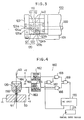
- a wire cut electric discharge machine to which an apparatus for detecting a failure in automatic wire extension according to a first embodiment of the present invention is mounted, comprises a Z axis unit 10 mounted to an upper column (not shown) in a manner vertically movable relative thereto, and a UV axis unit 20 mounted to the Z axis unit 10 so as to be vertically movable in unison therewith and horizontally movable relative thereto.
- An upper wire guide 30 is mounted to the unit 20 for movement in unison therewith.
- the upper wire guide 30 is, as a whole, formed into a hollow cylinder, and accommodates therein a pair of hold rollers 31 for holding a wire electrode (hereinafter referred to as wire) therebetween and feeding same downward during a wire extension operation, mentioned later.
- the hold rollers 31 are arranged to be movable toward and away from each other, and are coupled together through a one-way clutch (not shown) which is engaged when the rollers rotate in wire feed directions.
- the upper wire guide 30 is provided at a lower portion thereof with an annular holder 32 into which an upper nozzle 33 and a die guide 34 having a wire passage (not shown) bored therethrough are fitted, these elements 32 - 34 being disposed in alignment with one another.
- Supplied to the upper wire guide 30 through a pipe (not shown) is a machining fluid, which is then injected toward a workpiece 50 fixed on a worktable (not shown) through the wire passage of the die guide 34 and the upper nozzle 33.
- the electric discharge machine further comprises a lower wire guide 70 secured to a lower column 60 under the worktable.
- the lower wire guide 70 has a lower nozzle 71 at an inner end thereof and accommodates therein a three-point support guide (not shown), which is arranged in alignment with the upper nozzle 33 and the die guide 34 accommodated in the nozzle 33.
- a belt type wire conveying device 80 composed of a pair of belts, which are movable toward and away from each other and are adapted to travel while being urged against each other with the wire 40 therebetween during automatic wire extension, to thereby convey the wire.
- the electric discharge machine is further provided with an automatic wire extension unit 90 having a housing 91 which is secured to the UV axis unit 20 and to which a motor and a first piston-cylinder assembly (neither is shown) are mounted.
- a rod 92 which is rotatable in unison with the rotary shaft of the motor and axially movable relative thereto, has a lower end to which one end portion of an arm assembly 100 is secured, so that the arm assembly 100 is swung by the motor and moved vertically by the first piston-cylinder assembly.
- a wire cutting unit 110 comprising a stationary cutter 111 and a movable cutter 112 is provided the outer side of the other end portion of the arm assembly 100 in the width direction of the assembly.
- a wire extension nozzle 120 comprising a stationary nozzle portion 121 and a movable nozzle portion 122 is provided at the inner side of same in the assembly width direction.
- the stationary cutter 111 is secured to a frame member 102 which is detachably fixed to one end of the arm assembly body 101 by bolts, and the movable cutter 112 is secured to the distal end of a piston rod of a second piston-cylinder assembly (not shown) secured to the main body 101, such that, as the piston reciprocates, the movable cutter 112 is moved toward and away from the stationary cutter 111 together with the piston rod.
- a frame member 102 which is detachably fixed to one end of the arm assembly body 101 by bolts
- the movable cutter 112 is secured to the distal end of a piston rod of a second piston-cylinder assembly (not shown) secured to the main body 101, such that, as the piston reciprocates, the movable cutter 112 is moved toward and away from the stationary cutter 111 together with the piston rod.
- the stationary nozzle portion 121 is detachably fixed to the frame member 102 by bolts, and the movable nozzle portion 122 is detachably fixed by bolts to the distal end of a piston rod 130 of a third piston-cylinder assembly secured to the assembly body 101, so that, as the piston reciprocates, the movable nozzle portion 122 is moved toward and away from the stationary nozzle portion 121 in unison with the piston rod 130.
- the cutters 111, 112 and the nozzle portions 121, 122 are so arranged that when they are set apart from their counterparts, a slit 140 is defined between the opposed faces of these elements to allow the wire 40 to be passed therethrough.
- the nozzle portions 121, 122 are formed at their opposed surfaces thereof with semicylindrical holes, inverted semi-conical holes, small-diameter semicylindrical holes, and semicylindrical holes in the mentioned order from top to bottom, so as to define a cylindrical hole 123 into which an annular end 33a of the upper nozzle 33 is closely fitted, an inverted-cone shaped hole 124 communicating with a nozzle hole 33b of the upper nozzle 33, a nozzle hole 125 communicating with the hole 124, and a recess 126 into which a subnozzle 150 mentioned later is fitted, when the movable nozzle portion 122 is brought in contact with the stationary nozzle portion 121.
- the subnozzle 150 is electrically insulated from the main nozzle 120 and is made of an insulating material such as ceramic or the like.
- the subnozzle 150 is composed of two separate halves 150a and 150b, symmetrical with each other respect to a plane passing the axis of the subnozzle and each consisting of a semicylindrical main portion 151a, 151b and a semicylindrical extension 152a, 152b formed integrally and coaxially with the main portion.
- the subnozzle halves 150a, 150b are detachably fixed to the nozzle halves 121, 122 of the main nozzle 120, respectively, by appropriate means (not shown), so that, when the subnozzle halves 150a, 150b are joined together, the joined main portions 151a, 151b is fitted into the recess 126 of the main nozzle 120, and one subnozzle half 150b is movable in unison with the movable nozzle portion 122.
- the subnozzle halves 150a, 150b are each formed at opposed faces with an inverted semi-conical hole, opening in the upper surface of the main portion 151a, 151b, and a small-diameter semicylindrical hole, communicating at one end with the inverted semi-conical hole and opening at the other end in the lower surface of the extension 152a, 152b.
- an inverted cone-like hole 153 and a small-diameter cylindrical subnozzle hole 154 are defined in alignment with the axis of the subnozzle, which is coaxial with the nozzle hole 33b of the upper nozzle 33.
- the diameter of the hole 153 is 1.5 mm, for example, at the upper surface of the subnozzle, and the diameter of the same hole 153 at the extension side and the diameter of the hole 154 are 0.3 mm, for example.
- the electric discharge machine further includes a numerical control unit 170 constituting a part of a wire extension failure detecting apparatus 160 described later.
- the control unit 170 is connected to various operating parts of the electric discharge machine, such as respective power sources (e.g., motor, piston-cylinder assembly, etc.) of the movable portions of the Z axis unit 10, UV axis unit 20, hold rollers 31, worktable, movable sections of the three-point support guide, wire conveying device 80 and automatic wire extension unit 90, and is connected to an electric discharge power supply, a machining fluid supply system, and a sensor system.
- power sources e.g., motor, piston-cylinder assembly, etc.
- the wire extension failure detecting apparatus 160 is operable in a first detection mode for detecting a wire extension failure when carrying out a wire extension through a small-diameter machining initial hole 51 by using the main nozzle 120 and the subnozzle 150 in combination, and a second detection mode for detecting a wire extension failure when carrying out a wire extension through a machining initial hole 51 with a normal diameter by using the main nozzle 120 alone.
- the detecting apparatus 160 is provided with first and second short-circuit detecting circuits 161 and 162 of conventionally known type, including comparators and the like, and the numerical control unit 170 which has the function of discriminating between the detection modes and determining the success/failure of the wire extension, in addition to the conventionally known function of controlling the various operating parts of the electric discharge machine.
- the input terminal of the first short-circuit detecting circuit 161 is connected to a DC voltage source +V of a predetermined voltage, e.g., 10 V, through a first relay contact 163, and also connected to the main nozzle 120 which is electrically conductive.
- the input terminal of the second short-circuit detecting circuit 162 is connected to the same voltage source +V and also to the wire 40 through a contactor 164.
- the connection node between the second short-circuit detecting circuit 162 and the voltage source +V is grounded through a second relay contact 165.
- the output terminal of the first short-circuit detecting circuit 161 is connected to one input terminal of a first NAND circuit 166 whose another input terminal and both input terminals of a second NAND circuit 167 are connected to a computer (not shown) accommodated in the numerical control unit 170 through an output circuit (not shown) accommodated in the this unit.
- the output terminal of the second short-circuit detecting circuit 162 is connected to one input terminal of a third NAND circuit 168, the other input terminal of which is connected to the output terminal of the second NAND circuit 167.
- the output terminal of the third NAND circuit 168 is connected to one input terminal of a fourth NAND circuit 169.
- the other input terminal of the fourth NAND circuit 169 is connected to the output terminal of the first NAND circuit 166, and the output terminal of the circuit 169 is connected to the aforesaid computer through an input circuit (not shown) accommodated in the numerical control unit 170.
- Reference numeral 171 denotes a manual operation means for the selection of a detection mode, which comprises, for example, a manual data input device ordinarily provided in the numerical control unit 170 and connected to the computer through the input circuit.
- the computer is arranged to store flag information representing the selected detection mode in a predetermined register when a detection mode is selected by an operator by operating the manual data input device 171. Further, the computer is so arranged as to apply a detection mode select control output, through the output circuit, to driving coils of relays (not shown) respectively including the first and second relay contacts 163, 165, and to one input terminal of the first NAND circuit 166, when it reads, from an electric discharge machining program (not shown), a predetermined command to start a process for detecting a failure in wire extension.
- the select control output is also applied to one input terminal of the third NAND circuit 168 after it is inverted by the second NAND circuit 167.
- the workpiece 50 is grounded.
- an electric discharge is produced between the wire 40 and the workpiece 50 while the wire 40 is caused to travel by the wire feeding device, not shown, with the arm assembly 100 of the automatic wire extension unit 90 retracted sideways, and the machining fluid is injected from the upper and lower nozzles 33 and 71 toward the electric discharge machining region.
- the wire 40 is cut every time the electric discharge machining is completed for one product, and then a wire extension is carried out in a mode according to the diameter of the machining initial hole 51 (Fig. 1) into which the wire 40 is to be inserted next.
- a normal wire extension through a machining initial hole having a normal diameter, e.g., 2 mm or more, which is executed for producing an ordinary product not requiring extremely precise machining or the like, will be described.
- the operator selects the second detection mode by operating the manual data input device 171.
- the operation of the machining fluid supply system and wire conveying device is stopped, thereby interrupting the supply of the machining fluid and the feeding of the wire.
- the Z axis unit 10 is raised to move the upper wire guide 30 upward, and a pair of hold rollers 31 are driven to approach each other so as to hold the wire 40 therebetween.
- the arm assembly 100 which is in a retracted position, is lowered by the first piston-cylinder assembly via the rod 92 of the automatic wire extension unit 90, and then swung by the motor until the cutters 111, 112 come to a position just under the upper nozzle 33, whereby the wire 40 is introduced between the cutters 111 and 112 through the slit 140.
- the movable cutter 112 is driven by the second piston-cylinder assembly, to cut the wire 40.
- the arm assembly 100 is swung back toward the retracted position, the downstream side portion of the wire 40 is held between a pair of belts of the wire conveying device 80, and then, the same device 80 and a wire feed roller (not shown) are driven to discard the wire in a wire recovery container (not shown).
- the worktable is moved in a horizontal plane to a position where the center of the machining initial hole 51, which is bored through the workpiece 50 and into which the wire 40 is to be inserted, is aligned with the axes of the upper and lower wire guides 30 and 70.
- the arm assembly 100 is again swung toward the upper wire guide, to bring the main nozzle 120 to a position just under the upper nozzle 33.
- the third piston-cylinder assembly is driven to bring the movable nozzle portion 122 into contact with the stationary nozzle portion 121, and with the wire 40 held in the nozzle hole 125 defined by these two nozzle portions, the arm assembly 100 is raised such that the cylindrical hole 123 in the upper surface of the main nozzle receives the annular end 33a of the upper nozzle 33.
- a movable piece (not shown) of the three-point support guide is moved away from a stationary piece of same (not shown), thus permitting the insertion of the wire 40.
- the Z axis unit 10 is then lowered until the distance between the extreme end face of the main nozzle 120 and the upper surface of the workpiece 50 becomes equal to a predetermined value (11 to 13 mm) suited to a normal automatic wire extension.
- the computer of the numerical control unit 170 reads a command to detect a wire extension failure, and applies an L-level detection mode select control output to the first and second NAND circuits 166, 167 and the two relays, in accordance with the flag information representing the detection mode set by the aforementioned detection mode-setting operation of the operator.
- the first NAND circuit 166 is disabled, and the third and fourth NAND circuits 168 and 169 are enabled.
- the first and second relay contacts 163, 165 are opened, whereby a voltage of 10 V is applied from the voltage source +V to the wire 40 and the input terminal of the second short-circuit detecting circuit 162 via the contactor 164, while the application of the voltage to the main nozzle 120 is interrupted.
- the hold rollers 31 are rotated to feed the wire 40 toward the machining initial hole 51 and the lower wire guide 70.
- the wire 40 restrained by the jet of the machining fluid, passes through the machining initial hole 51 and then through the wire passage of the three-point support guide and between the stationary piece and movable piece of same, to the wire feed roller via the wire conveying device 80, thus completing a wire extension process.
- a voltage of 10 V is continuously applied to the input terminal of the second short-circuit detecting circuit 162 and accordingly an H-level signal is continuously supplied to the third NAND circuit 168 from the circuit 162. Therefore, an H-level signal representing nonoccurrence of a short circuit between the wire 40 and the workpiece 50 (i.e., wire extension failure) is continuously supplied to the numerical control unit 170 from the fourth NAND circuit 169.
- the upper wire guide 30 is raised together with the Z axis unit 10.
- the one-way clutch provided between the two hold rollers 31 is disengaged and thus the hold rollers 31 run idle.
- the arm assembly 100 is then lowered and the wire extension nozzle 120 is detached from the upper nozzle 33.
- the arm assembly 100 is swung back and then is raised up to the retracted position.
- the movable piece of the three-point support guide is driven toward the stationary piece thereof to slidably hold the wire 40 therebetween, and the hold rollers 31 and the belts of the wire conveying device 80 are driven in a direction such that they are moved away from their counterparts, thereby releasing the wire 40 from the rollers and the belts.
- the upper wire guide 30 is lowered to a predetermined height for preparation of an electric discharge machining operation.
- the related parts of the electric discharge machine are operated in accordance with basically the same procedure as that in the case of the normal wire extension already described. however, in this case, prior to the execution of the wire extension, the subnozzle 150 is previously attached to the bottom of the main nozzle 120, and the machining fluid is not supplied for the wire extension.
- the computer of the numerical control unit 170 reads the command to start the wire extension failure detection, and applies an H-level detection mode select control output to the first and second NAND circuits 166 and 167 and the two relays, in accordance with the flag information representing the detection mode set by the aforesaid mode setting operation of the operator.
- the second NAND circuit 167 is disabled, the first and fourth NAND circuits 166 and 169 are enabled, and the first and second relay contacts 163, 165 are closed, whereby the application of the voltage to the wire 40 and the input terminal of the second short-circuit detecting circuit 162 from the voltage source +V is interrupted, while a voltage of 10 V is applied to the main nozzle 120 from the voltage source +V.
- the hold rollers 31 are rotated to feed the wire of 0.2 mm in diameter, for example, toward the machining initial hole 51 having a small diameter (e.g., 0.5 to 2 mm) through the main nozzle 120 fitted onto the upper nozzle 33 and through the subnozzle 150 having a nozzle hole diameter of, for example, 0.3 mm, thereby starting a substantial wire extension.
- a small diameter e.g., 0.5 to 2 mm
- the computer starts detecting a wire extension failure in the first detection mode according to the flag information representing the detection mode and in accordance with the wire extension failure detection start command.
- the computer starts a timer (e.g., a software timer using a program), in which a predetermined time has been set.
- the predetermined time is set at a value slightly longer than a time period which is normally required for the wire 40 to reach a predetermined wire position (in this embodiment, the inlet of the subnozzle hole 154 of the subnozzle 150) from the time the substantial wire extension is started and which is previously calculated based on the distance between the position of the leading end of the wire at the time of starting the substantial wire extension and the predetermined wire position and the wire feed speed.
- the wire 40 can be smoothly inserted into the initial hole 51 without striking against the upper surface of the workpiece, even when the leading end of the wire is deflected due to the presence of liability to coil up.
- the wire 40 is further fed toward the lower wire guide 70 thereafter, it is passed through the wire passage of the lower nozzle 71, the wire passage of the three-point support guide accommodated in the lower wire guide 7 0, and between the movable and stationary pieces of the same guide, without any difficulty despite the liability of the wire to coil up, due to the wire guiding effect of the small-diameter machining initial hole 51. Then, the above-described post-processing is executed for preparation of an electric discharge machining operation.
- an occurrence of a wire extension failure is determined by the wire extension failure detecting apparatus 160 in the following manner.
- the computer ignores the detection output from the fourth NAND circuit 169 and makes no determination of wire extension failure based on the level of the same detection output.
- the wire 40 is slidably supported by the subnozzle 150 made of an electrically insulating material and is electrically insulated from the main nozzle 120 connected to the input terminal of the first short-circuit detecting circuit 161. Accordingly, even when the wire 40 is inserted into the machining initial hole 51 and touches its inner peripheral surface, a voltage of 10 V still appears at the input terminal of the first short-circuit detecting circuit 161, and therefore, an erroneous detection of the occurrence of wire extension failure never occurs.
- the wire 40 is inserted into the lower wire guide 70 without being flexed, and during this process, the output of the fourth NAND circuit 169 is maintained at the H-level and hence the computer determines that the wire extension is being executed normally.
- the input terminal of the first short-circuit detecting circuit 161 is connected to the ground potential through the main nozzle 120, the wire 40, the contactor 164 and the second relay contact 165, as well as through the main nozzle 120, the wire 40 and the workpiece 50.
- the subnozzle 150 is detached from the main nozzle 120 in advance.
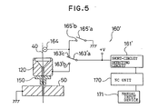
- a detecting apparatus 160′ As compared with the detecting apparatus 160 of Fig. 4 including the first and second short-circuit detecting circuits 161, 162 and the logic circuits provided between these detecting circuits and the NC unit 170, a detecting apparatus 160′ according to this embodiment is different in that it uses a single short-circuit detecting circuit 161′ to attain a simplified arrangement.
- the input terminal of the short-circuit detecting circuit 161′ is connected to a DC power supply +V and a movable contact 163′a of a first relay.
- the movable contact 163′a is arranged to be selectively connected to a first stationary contact 163′b of the first relay connected to the main nozzle 120, or a second stationary contact 163′c connected to a contactor 164 and a stationary contact 165′b of a second relay.
- the movable contact of the second relay is grounded.
- the detecting apparatus 160′ shown in Fig. 5 is operated in either of the first detection mode for detecting an unsuccessful wire extension during a wire extension operation using the main nozzle 120 and the subnozzle 150 in combination, and the second detection mode for detecting an unsuccessful wire extension during wire extension using only the main nozzle 120.
- the first detection mode in accordance with a detection mode select command from the NC unit 170, the movable contact 163′a of the first relay is connected to the first stationary contact 163′b, and the movable contact 165′a of the second relay is connected to the stationary contact 165′b to thereby connect the contactor 164 to the ground potential.
- the movable contact 163′a of the first relay is connected to the second stationary contact 163′c, and the movable contact 165′a of the second relay is disconnected from the stationary contact 165′b.
- the detecting apparatus 160′ is operated similarly to the aforementioned detecting apparatus 160 in other respects, and therefore, explanations thereof are omitted.
Landscapes
- Chemical & Material Sciences (AREA)
- Chemical Kinetics & Catalysis (AREA)
- Electrochemistry (AREA)
- Engineering & Computer Science (AREA)
- Mechanical Engineering (AREA)
- Electrical Discharge Machining, Electrochemical Machining, And Combined Machining (AREA)
Claims (6)
- Vorrichtung zum Fehlererkennen beim automatischen Drahteinfädeln, ausgeführt von einer Drahtschneide-Elektroerosionsmaschine mit einer Hauptdüse (120), einer Nebendüse (150), die an der Hauptdüse in einer elektrischisolierten Form angebracht werden kann, und eine Drahtelektrode (40), die in einem ersten Drahteinfädelmodus aus der Nebendüse (150) eingefädelt wird,
wobei diese Vorrichtung umfaßt: -
eine Schaltung zum Erkennen eines Kurzschlusses (161, 161′), die mit der Hauptdüse (120) und Drahtelektrode (40) verbunden ist und zur Erzeugung eines vorbestimmten Erkennungsausgangs ausgelegt ist, wenn ein Kurzschluß zwischen der Drahtelektrode (40) und der Hauptdüse (120) auftritt;
Mittel zum Abschalten (170, 163, 165; 170, 163′, 165′), die mit der Schaltung zum Erkennen eines Kurzschlusses verbunden und in der Lage sind, den vorbestimmten Erkennungsausgang von ihr nach dem Start des Drahteinfädelns unwirksam zu machen, bis die Drahtelektrode eine vorbestimmte Zuführposition erreicht; und
Mittel zum Unterscheiden (170), welches ansprechbar auf den genannten vorbestimmten Erkennungsausgang und in der Lage ist zu erkennen, daß das Drahteinfädeln in einem Fehler geendet hat, wenn der vorbestimmte Erkennungsausgang durch die Schaltung zum Erkennen eines Kurzschlusses erzeugt wurde, nachdem die Schaltung zum Erkennen eines Kurzschlusses aus einem abgeschalteten Zustand freigegeben wurde. - Vorrichtung nach Anspruch 1, ferner umfassend eine Spannungsquelle, die mit der Eingangsseite der Schaltung zum Erkennen eines Kurzschlusses (161) verbunden ist.
- Vorrichtung nach Anspruch 1 zur Verwendung in einer Drahtschneide-Elektroerosionsmaschine, bei welcher die genannte Drahtelektrode (40) in einem zweiten Drahteinfädelmodus auch aus der Hauptdüse (120) eingefädelt werden kann, wobei:-
dieses mittel zum Unterscheiden bestimmt, ob der erste oder zweite Drahteinfädelmodus ausgeführt wird;
die genannte Vorrichtung ferner eine zweite Schaltung zum Erkennen eines Kurzschlusses (162) enthält, die mit der Drahtelektrode (40) und einem Potential eines Werkstücks verbunden ist und einen zweiten vorbestimmten Erkennungsausgang erzeugt, wenn ein Kurzschluß zwischen der Drahtelektrode (40) und dem Werkstück in dem zweiten Drahteinfädelmodus auftritt; und
das genannte Mittel zum Unterscheiden erkennt, daß das Drahteinfädeln in einem Fehler geendet hat, wenn der zweite vorbestimmte Erkennungsausgang erzeugt wird. - Vorrichtung nach Anspruch 3, ferner umfassend eine Spannungsquelle, die mit einer Eingangsseite der ersten Schaltung zum Erkennen eines Kurzschlusses (161) verbunden werden kann und mit einer Eingangsseite der genannten Schaltung zum Erkennen eines Kurzschlusses (162) verbunden ist.
- Vorrichtung nach Anspruch 4, ferner umfassend:-
einen ersten Schalter (163) der zwischen der Spannungsquelle und der Eingangsseite der ersten Schaltung zum Erkennen eines Kurzschlusses (161) angeordnet ist;
einen zweiten Schalter (165), dessen eine Seite mit einem Verbindungsknoten zwischen der Spannungsquelle und der Eingangsseite der zweiten Schaltung zum Erkennen eines Kurzschlusses (162) verbunden ist und dessen andere Seite geerdet ist; und
eine Logikschaltung (166 bis 169), die zwischen dem Mittel zum Unterscheiden (170) und der ersten und zweiten Schaltung zum Erkennen eines Kurzschlusses (161, 162) angeordnet ist;
genannte Mittel zum Unterscheiden (170), die abhängig davon, ob der erste oder zweite Drahteinfädelmodus ausgeführt wird, zum Steuern der Positionen der ersten und zweiten Schalter (163, 165) und des Betriebs der Logikschaltung (166 bis 169) ausgelegt ist. - Vorrichtung nach Anspruch 2 zur Verwendung in einer Drahtschneide-Elektroerosionsmaschine, in der die genannte Drahtelektrode (40) auch von der Hauptdüse (120) in einem zweiten Drahteinfädelmodus eingefädelt werden kann, wobei diese Vorrichtung ferner umfaßt:-
einen ersten Schalter (163), um die Spannungsquelle und die Eingangsseite der Schaltung zum Erkennen eines Kurzschlusses (161′) mit der Hauptdüse (120) oder der Drahtelektrode (40) zu verbinden; und
einen zweiten Schalter (165), um die Drahtelektrode (40) nach Wahl erden zu können;
genanntes Mittel zum Unterscheiden (170), das Mittel (171) enthält, welches in der Lage ist zu erkennen, ob der erste oder zweite Drahteinfädelmodus ausgeführt wird, und die Positionen des ersten und zweiten Schalters (163, 165) in Abhängigkeit von dem Ergebnis der Erkennung schalten kann.
Applications Claiming Priority (2)
| Application Number | Priority Date | Filing Date | Title |
|---|---|---|---|
| JP63252894A JPH02100828A (ja) | 1988-10-08 | 1988-10-08 | 自動ワイヤ結線不良検出方式 |
| JP252894/88 | 1988-10-08 |
Publications (3)
| Publication Number | Publication Date |
|---|---|
| EP0390933A1 EP0390933A1 (de) | 1990-10-10 |
| EP0390933A4 EP0390933A4 (en) | 1991-03-13 |
| EP0390933B1 true EP0390933B1 (de) | 1993-01-27 |
Family
ID=17243648
Family Applications (1)
| Application Number | Title | Priority Date | Filing Date |
|---|---|---|---|
| EP89911102A Expired - Lifetime EP0390933B1 (de) | 1988-10-08 | 1989-10-04 | Vorrichtung zur fehlererkennung beim automatischen drahteinfadeln |
Country Status (4)
| Country | Link |
|---|---|
| US (1) | US5051553A (de) |
| EP (1) | EP0390933B1 (de) |
| JP (1) | JPH02100828A (de) |
| WO (1) | WO1990003863A1 (de) |
Families Citing this family (10)
| Publication number | Priority date | Publication date | Assignee | Title |
|---|---|---|---|---|
| JPH0360925A (ja) * | 1989-07-27 | 1991-03-15 | Mitsubishi Electric Corp | ワイヤ放電加工装置 |
| JP2616099B2 (ja) * | 1990-02-27 | 1997-06-04 | 三菱電機株式会社 | ワイヤ放電加工装置 |
| JP3234056B2 (ja) * | 1993-07-13 | 2001-12-04 | ファナック株式会社 | ワイヤ放電加工機におけるワイヤ障害発生位置検出方法及び装置 |
| US5523545A (en) * | 1995-02-16 | 1996-06-04 | Ona Electro-Erosion, S.A. | Device for detecting successful threading on electrical discharge machines |
| JP4775904B2 (ja) * | 2006-08-10 | 2011-09-21 | 日置電機株式会社 | 巻線機 |
| JP5088975B2 (ja) * | 2010-10-19 | 2012-12-05 | 株式会社ソディック | ワイヤ放電加工装置 |
| JP4938137B1 (ja) * | 2011-03-03 | 2012-05-23 | ファナック株式会社 | 被加工物の上面検出機能を有するワイヤカット放電加工機 |
| CN104493322B (zh) * | 2014-12-23 | 2017-01-25 | 胡力权 | 免穿丝导丝嘴 |
| JP6017096B1 (ja) * | 2015-10-30 | 2016-10-26 | 三菱電機株式会社 | ワイヤ放電加工機、ワイヤ放電加工機の制御装置の制御方法及び位置決め方法 |
| CN112260238A (zh) * | 2020-09-29 | 2021-01-22 | 北海职业学院 | 一种线路短路故障自动检测切除装置 |
Family Cites Families (9)
| Publication number | Priority date | Publication date | Assignee | Title |
|---|---|---|---|---|
| JPS58177234A (ja) * | 1982-04-07 | 1983-10-17 | Mitsubishi Electric Corp | ワイヤカツト放電加工装置におけるワイヤ自動供給方法 |
| JPS59196128A (ja) * | 1983-04-19 | 1984-11-07 | Fanuc Ltd | ワイヤカツト放電加工機 |
| JPS629827A (ja) * | 1985-07-04 | 1987-01-17 | Fanuc Ltd | ワイヤカツト放電加工方法と装置 |
| JPS6263019A (ja) * | 1985-09-13 | 1987-03-19 | Fanuc Ltd | 自動結線終了検出装置 |
| JPH0669651B2 (ja) * | 1985-11-20 | 1994-09-07 | 三菱電機株式会社 | ワイヤ自動供給装置 |
| JPH0818186B2 (ja) * | 1986-01-14 | 1996-02-28 | 株式会社井上ジャパックス研究所 | ワイヤカツト放電加工装置 |
| JPS62165242A (ja) * | 1986-01-17 | 1987-07-21 | Toshiba Corp | プロセツサ |
| JPS6362614A (ja) * | 1986-08-30 | 1988-03-18 | Fanuc Ltd | ワイヤカツト放電加工装置 |
| JP2566764B2 (ja) * | 1986-11-05 | 1996-12-25 | 株式会社ソディック | ワイヤカツト放電加工装置用自動通線装置 |
-
1988
- 1988-10-08 JP JP63252894A patent/JPH02100828A/ja active Pending
-
1989
- 1989-10-04 EP EP89911102A patent/EP0390933B1/de not_active Expired - Lifetime
- 1989-10-04 US US07/490,608 patent/US5051553A/en not_active Expired - Fee Related
- 1989-10-04 WO PCT/JP1989/001020 patent/WO1990003863A1/ja not_active Ceased
Also Published As
| Publication number | Publication date |
|---|---|
| EP0390933A1 (de) | 1990-10-10 |
| US5051553A (en) | 1991-09-24 |
| EP0390933A4 (en) | 1991-03-13 |
| WO1990003863A1 (fr) | 1990-04-19 |
| JPH02100828A (ja) | 1990-04-12 |
Similar Documents
| Publication | Publication Date | Title |
|---|---|---|
| EP0390933B1 (de) | Vorrichtung zur fehlererkennung beim automatischen drahteinfadeln | |
| JPH0796168B2 (ja) | ワイヤ放電加工装置のワイヤ自動供給装置 | |
| KR101199810B1 (ko) | 와이어 컷 방전 가공기에 있어서의 단선 수복 방법 | |
| KR900009030B1 (ko) | 자동 결선 종료 검출 장치 | |
| US4816636A (en) | Wire cut electric discharge machine | |
| US5057663A (en) | Automatic wire extension method | |
| TW202306692A (zh) | 車床、及其切斷車刀破損檢測方法 | |
| US5340958A (en) | Method and apparatus for wire feeding in a wire-cut electroerosion apparatus | |
| JP2684392B2 (ja) | ワイヤ電極供給確認方法 | |
| EP0406429B1 (de) | Selbsttätiges drahtverbindungsverfahren | |
| EP0364591A1 (de) | Elektroerosionsbearbeitungsmaschine mit vermeidung der elektrolytischen korrosion durch die spannung zum nachweis von kurzschluss | |
| JPH07299660A (ja) | ワイヤカット放電加工用ノズル装置 | |
| JP2681809B2 (ja) | ワイヤ放電加工用制御装置 | |
| JPS6263018A (ja) | ワイヤカツト放電加工機におけるワイヤ電極断線位置検出方法 | |
| SU1009684A1 (ru) | Устройство дл автоматической заправки электрода-проволоки в электроэрозионных вырезных станках | |
| JPS629826A (ja) | ワイヤカツト放電加工機の加工経過表示方法 | |
| JP3420833B2 (ja) | ワイヤ放電加工機の中子処理装置 | |
| KR100302278B1 (ko) | 공작기계의소재커팅완료검출방법및장치 | |
| JPH05305523A (ja) | ワイヤ放電加工機におけるワイヤ電極の自動結線装置 | |
| JPH0386428A (ja) | ワイヤカット放電加工機の断線修復方法 | |
| JPH05305522A (ja) | ワイヤ放電加工機におけるワイヤ電極の切断装置 | |
| JP2000218440A (ja) | ワイヤ放電加工機 | |
| JP3927381B2 (ja) | ワーク加工機のワーク加工方法 | |
| JPH02198745A (ja) | タツプ折損検知機構 | |
| KR20190009652A (ko) | 모재와 와이어의 터치를 센싱하는 용접 장치 |
Legal Events
| Date | Code | Title | Description |
|---|---|---|---|
| PUAI | Public reference made under article 153(3) epc to a published international application that has entered the european phase |
Free format text: ORIGINAL CODE: 0009012 |
|
| 17P | Request for examination filed |
Effective date: 19900613 |
|
| AK | Designated contracting states |
Kind code of ref document: A1 Designated state(s): CH DE FR GB LI |
|
| A4 | Supplementary search report drawn up and despatched |
Effective date: 19910123 |
|
| AK | Designated contracting states |
Kind code of ref document: A4 Designated state(s): CH DE FR GB LI |
|
| 17Q | First examination report despatched |
Effective date: 19911205 |
|
| GRAA | (expected) grant |
Free format text: ORIGINAL CODE: 0009210 |
|
| AK | Designated contracting states |
Kind code of ref document: B1 Designated state(s): CH DE LI |
|
| REF | Corresponds to: |
Ref document number: 68904647 Country of ref document: DE Date of ref document: 19930311 |
|
| EN | Fr: translation not filed | ||
| PLBE | No opposition filed within time limit |
Free format text: ORIGINAL CODE: 0009261 |
|
| STAA | Information on the status of an ep patent application or granted ep patent |
Free format text: STATUS: NO OPPOSITION FILED WITHIN TIME LIMIT |
|
| 26N | No opposition filed | ||
| PGFP | Annual fee paid to national office [announced via postgrant information from national office to epo] |
Ref country code: DE Payment date: 19951012 Year of fee payment: 7 |
|
| PGFP | Annual fee paid to national office [announced via postgrant information from national office to epo] |
Ref country code: CH Payment date: 19951027 Year of fee payment: 7 |
|
| PG25 | Lapsed in a contracting state [announced via postgrant information from national office to epo] |
Ref country code: LI Effective date: 19961031 Ref country code: CH Effective date: 19961031 |
|
| REG | Reference to a national code |
Ref country code: CH Ref legal event code: PL |
|
| PG25 | Lapsed in a contracting state [announced via postgrant information from national office to epo] |
Ref country code: DE Effective date: 19970701 |