EP0394894A1 - Stator interne HP-MP unique de turbine à vapeur avec climatisation controlée - Google Patents
Stator interne HP-MP unique de turbine à vapeur avec climatisation controlée Download PDFInfo
- Publication number
- EP0394894A1 EP0394894A1 EP90107617A EP90107617A EP0394894A1 EP 0394894 A1 EP0394894 A1 EP 0394894A1 EP 90107617 A EP90107617 A EP 90107617A EP 90107617 A EP90107617 A EP 90107617A EP 0394894 A1 EP0394894 A1 EP 0394894A1
- Authority
- EP
- European Patent Office
- Prior art keywords
- stator
- vein
- internal
- space
- interstatoric
- Prior art date
- Legal status (The legal status is an assumption and is not a legal conclusion. Google has not performed a legal analysis and makes no representation as to the accuracy of the status listed.)
- Granted
Links
- 238000001816 cooling Methods 0.000 title description 3
- 210000003462 vein Anatomy 0.000 description 20
- 208000031968 Cadaver Diseases 0.000 description 5
- 230000006978 adaptation Effects 0.000 description 5
- 238000003303 reheating Methods 0.000 description 4
- 238000004378 air conditioning Methods 0.000 description 3
- 239000011248 coating agent Substances 0.000 description 3
- 238000000576 coating method Methods 0.000 description 3
- 238000007789 sealing Methods 0.000 description 3
- 230000035882 stress Effects 0.000 description 2
- 238000010408 sweeping Methods 0.000 description 2
- 230000001143 conditioned effect Effects 0.000 description 1
- 239000000470 constituent Substances 0.000 description 1
- 238000010276 construction Methods 0.000 description 1
- 238000007599 discharging Methods 0.000 description 1
- 230000000284 resting effect Effects 0.000 description 1
- 230000008646 thermal stress Effects 0.000 description 1
- 238000011144 upstream manufacturing Methods 0.000 description 1
Images


Classifications
-
- F—MECHANICAL ENGINEERING; LIGHTING; HEATING; WEAPONS; BLASTING
- F01—MACHINES OR ENGINES IN GENERAL; ENGINE PLANTS IN GENERAL; STEAM ENGINES
- F01D—NON-POSITIVE DISPLACEMENT MACHINES OR ENGINES, e.g. STEAM TURBINES
- F01D9/00—Stators
-
- F—MECHANICAL ENGINEERING; LIGHTING; HEATING; WEAPONS; BLASTING
- F01—MACHINES OR ENGINES IN GENERAL; ENGINE PLANTS IN GENERAL; STEAM ENGINES
- F01D—NON-POSITIVE DISPLACEMENT MACHINES OR ENGINES, e.g. STEAM TURBINES
- F01D25/00—Component parts, details, or accessories, not provided for in, or of interest apart from, other groups
- F01D25/24—Casings; Casing parts, e.g. diaphragms, casing fastenings
- F01D25/26—Double casings; Measures against temperature strain in casings
-
- F—MECHANICAL ENGINEERING; LIGHTING; HEATING; WEAPONS; BLASTING
- F01—MACHINES OR ENGINES IN GENERAL; ENGINE PLANTS IN GENERAL; STEAM ENGINES
- F01D—NON-POSITIVE DISPLACEMENT MACHINES OR ENGINES, e.g. STEAM TURBINES
- F01D25/00—Component parts, details, or accessories, not provided for in, or of interest apart from, other groups
- F01D25/08—Cooling; Heating; Heat-insulation
- F01D25/12—Cooling
Definitions
- the present invention relates to an HP-MP steam turbine body according to the preamble of claim 1.
- the internal stators HP (high pressure) and MP (medium pressure) are separated by an interval and each provided with a sealing device separated from each other and having the function of reducing the natural leakage of vapor from the HP vein to the MP vein.
- Part of the leak passes through the gap between the two sealing devices and is evacuated through the gap between the two internal stators in the interstatoric space; this space is thus swept by steam at high temperature, its evacuation taking place through the thermal protection means.
- the vapor sweep in the interstatoric space thus traverses the entire space, from the axial positioning means to the thermal protection means.
- the evacuation means are provided with means for adapting the vapor flow rate, which makes it possible to adapt the air conditioning to the desired level.
- the means for discharging this vapor are connected to the inlet of the reheating device supplying the vein MP.
- At least part of the surface of the internal stator facing the rotor between the HP and MP veins is provided with a coating with low thermal conductivity.
- the means for withdrawing steam sending this steam into the interstatoric space are constituted by pipes formed in bosses of the internal stator arranged symmetrically with respect to the axis of the turbine.
- the means for evacuating vapor from the interstatoric space include: - grooves formed in the part of the axial positioning means integral with the internal stator and opening into cavities formed in the part of the axial positioning means integral with the external stator, - Chimneys passing through the external stator opening into said cavities, said chimneys being provided with plunging pipes connected to the inlet of the reheating device.
- the external stator is thus protected from too strong convections.
- the known turbine body shown in FIG. 1 comprises a single rotor 1 comprising an HP part 2 and an MP part 3 separated by a part 4 receiving the seals.
- An internal HP stator 5 defines with HP part 2 an HP vein 6.
- An internal MP 7 stator defines with the MP 3 part an MP 8 vein.
- the two internal stators 5 and 7 are interconnected. They are positioned axially inside an external stator 9 by sealed positioning means 11.
- an HP exhaust 15 connected through a reheating device 16 to MP intake means 17 which supply the inlet 18 of the MP stream 8.
- the external stator 9 and the internal stators 5 and 7 define with the positioning means 11 and the thermal screen 10 an interstatoric space 19.
- the axial positioning means 11 and the heat shield 10 are spaced from the inlets 12 and 18 of the HP 6 and MP 8 veins, so that the interstatoric space 19 surrounds all of the hot stages of the HP 6 and MP 8 veins .
- seals 20 and 21 are arranged to separate the inlet 12 of the HP vein 6 from the inlet 18 of the vein 8.
- the vapor entered through the interval 22 escapes towards the outlet 14 of the HP vein 6 through a slot 23 formed in the screen 10.
- the HP-MP turbine body according to the invention is shown in FIG. 2.
- the body according to the invention comprises a single internal stator 57.
- the sealing means 20, 21 arranged in part 4 are in one piece.
- the axial positioning means 11 are sealed and likewise the thermal protection means 10 are also sealed.
- the interstatoric space 19 surrounds almost all of the stages of the HP vein 6 and the hot stages of the MP vein 8.
- An inlet 24 into the interstatoric space is provided in the internal stator 57 in the vicinity of the thermal protection means 10. This inlet brings into the space 9 the vapor drawn off at the outlet of one of the last stages of the HP vein 6 , for example, upstream of the last stage 25.
- an outlet 26 connected to the HP exhaust 15 by a pipe 28 provided with an adaptation device 27.
- This device is for example a pierced plate or a valve.
- the adaptation member 27 the temperature distribution along the axis can be adjusted more precisely.
- the members 27 By adjusting the members 27 differently, the cooling of the interstatoric space 29 can be adjusted. azimuth.
- the vapor flow sweeping the interstatoric space optimally cools the internal 57 and external 9 stators which allows a low thermal gradient at the internal body 57 as well as low temperatures of bolts and external stator. This makes it possible to have a smaller dimensioning of the bolts and of the external stator 9.
- the tightness of the thermal protection device 10 protects the hot parts from any random entry of cold vapor coming from the exit from the HP vein.
- the part of the internal stator 57 is coated in the vicinity of the inlet 12 of the HP stream 6 with a coating 29 of low thermal conductivity. Likewise, the part of the internal stator 57 in the vicinity of the inlet 18 of the vein MP 8 is provided with a coating 29 with low thermal conductivity.
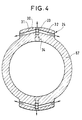
- the internal stator 57 in the vicinity of the thermal protection means 10 has bosses 30. Lateral pipes 31, 32 and a radial pipe 33 are provided in each boss (see fig. 4) .
- the pipes 31, 32, 33 are supplied by a socket 34 located in the HP stream 6 and open into the interstatoric space 19 in the vicinity of the thermal protection means 10.
- the bosses 30 are symmetrical with respect to the axis of the turbine.
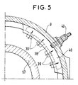
- the axial positioning means 11 consist of a first part 35 secured to the internal stator 57, resting on a part 36 secured to the external stator 9 between a support 37 and a counter-support 38.
- Grooves 39 have been made in the part 35 and open into a cavity 40 of the part 36.
- a chimney 41 opening into the cavity 40 is formed in the external stator 9.
- Each chimney 41 is provided with a plunging pipe 42 serving to evacuate the steam to the flow control device 27 (figure 2). These pipes 42 protect the external stator 9 from too much convection.
- each of these pipes 42 evacuates the steam to a flow adaptation device 27.
- each of the adaptation devices 27 By adjusting each of the adaptation devices 27, it is possible to adjust the cooling in azimuth in the interstatoric space 19.
Landscapes
- Engineering & Computer Science (AREA)
- Mechanical Engineering (AREA)
- General Engineering & Computer Science (AREA)
- Turbine Rotor Nozzle Sealing (AREA)
- Engine Equipment That Uses Special Cycles (AREA)
- Organic Low-Molecular-Weight Compounds And Preparation Thereof (AREA)
- Control Of Turbines (AREA)
Abstract
Les parties du stator interne qui entourent la totalité de la détente de la veine HP (6) et les étages chauds de la veine MP (8) sont ainsi climatisés de façon optimale, ce qui permet de diminuer le gradient thermique supporté par le stator interne (57) ainsi que la température des boulons des stators (57) et (9).
Description
- La présente invention concerne un corps de turbine à vapeur HP-MP selon le préambule de la revendication 1.
- Dans le corps de turbine connu les stators internes HP (haute pression) et MP (moyenne pression) sont séparés par un intervalle et munis chacun d'un dispositif d'étanchéité séparés l'un de l'autre et ayant pour fonction de réduire la fuite naturelle de vapeur de la veine HP vers la veine MP. Une partie de la fuite passe dans l'intervalle entre les deux dispositifs d'étanchéité et est évacuée par l'intervalle ménagé entre les deux stators internes dans l'espace interstatorique ; cet espace est ainsi balayé par de la vapeur à haute température, son évacuation se faisant à travers les moyens de protection thermique.
- Grâce à cette circulation de vapeur, on climatise les stators interne et externe permettant ainsi d'abaisser la température du stator externe ce qui permet de réduire ses dimensions.
- Mais la climatisation réalisée ainsi par le balayage de vapeur est imparfaite. En effet, la température de la vapeur injectée dans l'espace interstatorique est élevée et donc le stator externe ainsi que la boulonnerie des stators internes HP et MP sont à une température élevée.
- Le corps de turbine selon l'invention ne présentant pas ces inconvénients est défini par la partie caractérisante de la revendication 1.
- En prélevant de la vapeur à plus faible température pour climatiser les stators interne et externe, au niveau d'un étage de la veine HP, on peut diminuer la température supportée par le stator externe ainsi que la température supportée par le boulonnage du stator externe et du stator interne HP-MP.
- Le balayage de vapeur dans l'espace interstatorique parcourt ainsi la totalité de l'espace, des moyens de positionnement axial aux moyens de protection thermique.
- Enfin, comme il n'y a plus d'intervalle entre stator interne HP et stator interne MP, ces deux stators sont remplacés par un stator unique interne permettant de diminuer l'encombrement axial.
- Les moyens d'évacuation sont munis de moyens d'adaptation du débit de vapeur ce qui permet d'adapter la climatisation au niveau voulu.
- Les moyens d'évacuation de cette vapeur sont reliés à l'entrée du dispositif de resurchauffe alimentant la veine MP.
- Selon un perfectionnement de l'invention, au moins une partie de la surface du stator interne en regard du rotor entre les veines HP et MP est munie d'un revêtement à faible conductibilité thermique.
- On diminue ainsi les contraintes thermiques transmises au stator interne dans la partie la plus chaude des veines HP et MP.
- Selon une réalisation préférentielle de l'invention, les moyens de prélèvement de vapeur envoyant cette vapeur dans l'espace interstatorique sont constitués par des canalisations ménagées dans des bossages du stator interne disposés symétriquement par rapport à l'axe de la turbine.
- Les moyens d'évacuation de vapeur de l'espace interstatorique comportent :
- des rainures ménagées dans la partie des moyens de positionnement axial solidaires du stator interne et débouchant dans des cavités ménagées dans la partie des moyens de positionnement axial solidaires du stator externe,
- des cheminées traversant le stator externe débouchant dans lesdites cavités, lesdites cheminées étant munies de tuyauteries plongeantes reliées à l'entrée du dispositif de resurchauffe. - Le stator externe est ainsi protégé des trop fortes convections.
- La présente invention sera mieux comprise à la lumière de la description qui va suivre dans laquelle :
- La figure 1 représente en demi-coupe axiale un corps de turbine HP-MP connu.
- La figure 2 représente en demi-coupe axiale un corps de turbine HP-MP selon l'invention.
- La figure 3 représente une demi-coupe axiale détaillée d'une réalisation préférentielle de l'invention.
- La figure 4 représente une coupe partielle selon le plan AA du corps de la figure 3.
- La figure 5 représente une coupe partielle selon le plan BB du corps de la figure 3.
- La figure 6 représente une perspective du détail du corps représenté à la figure 5.
- Le corps de turbine connu représenté à la figure 1 comporte un rotor unique 1 comprenant une partie HP 2 et une partie MP 3 séparées par une partie 4 recevant les étanchéités.
- Un stator interne HP 5 définit avec la partie HP 2 une veine HP 6.
- Un stator interne MP 7 définit avec la partie MP 3 une veine MP 8.
- Les deux stators internes 5 et 7 sont reliés entre eux. Ils sont positionnés axialement à l'intérieur d'un stator externe 9 par des moyens de positionnement 11 étanches.
- D'autre part, les parties chaudes des stators internes HP 5 et MP 7 sont protégés thermiquement par un écran 10 non étanche.
- La vapeur est injectée à l'entrée 12 de la veine HP 6 par des moyens d'admission 13.
- A la sortie 14 de la veine HP 6 est disposé un échappement HP 15 relié à travers un dispositif de resurchauffe 16 à des moyens d'admission MP 17 qui alimentent l'entrée 18 de la veine MP 8.
- Le stator externe 9 et les stators internes 5 et 7 définissent avec les moyens de positionnement 11 et l'écran thermique 10 un espace interstatorique 19.
- Les moyens de positionnement axial 11 et l'écran thermique 10 sont écartés des entrées 12 et 18 des veines HP 6 et MP 8, de façon à ce que l'espace interstatorique 19 entourent la totalité des étages chauds des veines HP 6 et MP 8.
- Au droit de la partie 4 sont disposées des garnitures d'étanchéité 20 et 21 pour séparer l'entrée 12 de la veine HP 6 de l'entrée 18 de la veine 8.
- Ces deux garnitures 20, 21 sont écartées axialement par un intervalle 22 entre les stators internes 5 et 7 pour permettre l'alimentation en vapeur de l'espace interstatorique 19.
- La vapeur entrée par l'intervalle 22 s'échappe vers la sortie 14 de la veine HP 6 par une fente 23 ménagée dans l'écran 10.
- Cette vapeur climatise les stators interne et externe ce qui permet de diminuer le gradient de température supporté par les stators internes 5 et 7 et donc les sollicitations.
- Toutefois, en raison de la température élevée de la vapeur injectée le stator externe 9 ainsi que la boulonnerie des stators internes sont à une température élevée.
- D'autre part, l'expérience montre que la vapeur froide venant de l'échappement HP passe au delà de l'écran thermique 10 vers l'espace interstatorique 19 et crée une dissymétrie dans les températures ainsi que des contraintes dans les parties chaudes des stators internes HP et MP.
- Le corps de turbine HP-MP selon l'invention est représenté à la figure 2.
- Les éléments constitutifs de ce corps semblables à ceux du corps connu représenté à la figure 1 portent les mêmes références.
- Le corps selon l'invention comporte un stator interne unique 57. Les moyens d'étanchéité 20, 21 disposés dans la partie 4 sont d'une seule pièce.
- Les moyens de positionnement axial 11 sont étanches et de même les moyens de protection thermique 10 sont également étanches.
- L'espace interstatorique 19 entoure la quasi totalité des étages de la veine HP 6 et les étages chauds de la veine MP 8.
- Une admission 24 dans l'espace interstatorique est ménagée dans le stator interne 57 au voisinage des moyens de protection thermique 10. Cette admission amène dans l'espace 9 la vapeur soutirée à la sortie de l'un des derniers étages de la veine HP 6, par exemple, en amont du dernier étage 25.
- Dans le stator externe 9 est ménagée une évacuation 26 reliée à l'échappement HP 15 par une canalisation 28 munie d'un dispositif d'adaptation 27. Ce dispositif est par exemple une plaque percée ou une vanne.
- La vapeur qui s'échappe de l'espace interstatorique est ainsi recyclée dans le dispositif de resurchauffe 16.
- En choisissant l'étage de la veine HP sur lequel on prélève de la vapeur, on peut obtenir l'ordre de grandeur voulu pour la température de la vapeur balayant l'espace interstatorique 19.
- Grâce à l'organe d'adaptation 27, on peut régler avec plus de précision la distribution de température le long de l'axe. En général on aura plusieurs évacuations 26 disposées symétriquement autour de l'axe, chacune étant reliée à une canalisation 28 munie d'un organe d'adaptation 27. En réglant différemment les organes 27 on peut régler le refroidissement de l'espace interstatorique 29 en azimut.
- Ainsi le débit de vapeur balayant l'espace interstatorique climatise de façon optimale les stators interne 57 et externe 9 ce qui permet d'avoir un gradient thermique faible au niveau du corps interne 57 ainsi que des températures basses de boulons et de stator externe. Ceci permet d'avoir un dimensionnement plus faible des boulons et du stator externe 9.
- D'autre part, l'étanchéité du dispositif de protection thermique 10 protège les parties chaudes de toute entrée aléatoire de vapeur froide venant de la sortie de la veine HP.
- De plus, la construction du stator interne est plus simple.
- On revêt la partie du stator interne 57 au voisinage de l'entrée 12 de la veine HP 6 d'un revêtement 29 à faible conductibilité thermique. De même, la partie du stator interne 57 au voisinage de l'entrée 18 de la veine MP 8 est pourvue d'un revêtement 29 à faible conductibilité thermique.
- Dans la réalisation particulière représentée aux figures 3 à 6, le stator interne 57 au voisinage des moyens de protection thermique 10 comporte des bossages 30. Des canalisations 31, 32 latérales et une canalisation radiale 33 sont ménagées dans chaque bossage (voir fig.4).
- Les canalisations 31, 32, 33 sont alimentées par une prise 34 située dans la veine HP 6 et débouchent dans l'espace interstatorique 19 au voisinage des moyens de protection thermique 10.
- Les bossages 30 sont symétriques par rapport à l'axe de la turbine.
- Les moyens de positionnement axial 11 sont constitués d'une première partie 35 solidaire du stator interne 57, reposant sur une partie 36 solidaire du stator externe 9 entre un appui 37 et un contre-appui 38.
- Des rainures 39 ont été ménagées dans la partie 35 et débouchent dans une cavité 40 de la pièce 36. Une cheminée 41 débouchant dans la cavité 40 est ménagée dans le stator externe 9. Chaque cheminée 41 est munie d'une tuyauterie plongeante 42 servant à évacuer la vapeur vers le dispositif de réglage de débit 27 (figure 2). Ces tuyauteries 42 protègent le stator externe 9 d'une trop grande convection.
- De préférence on dispose quatre cavités 40 avec leurs tuyauteries 42 réparties régulièrement autour de l'axe de la turbine. Chacune de ces tuyauteries 42 évacue la vapeur vers un dispositif d'adaptation de débit 27. En réglant chacun des dispositifs d'adaptation 27, on peut régler le refroidissement en azimut dans l'espace interstatorique 19.
Claims (6)
- un stator interne HP définissant avec la partie HP (2) du rotor une veine HP (6),
- un stator interne MP définissant avec la partie MP (3) du rotor une veine MP (8),
- le stator interne HP et le stator interne MP étant positionnés axialement à l'intérieur d'un stator externe (9) par des moyens étanches de positionnement axial (11) situés autour de la veine MP (8) dans une plan éloigné de l'entrée (18) de ladite veine MP (8), des moyens de protection thermique (10) étant situés autour de la veine HP (6) dans un plan écarté de l'entrée (12) de ladite veine HP (6), lesdits moyens de positionnement (11) et lesdits moyens de protection thermique (10) définissant avec les stators internes HP et MP et le stator externe (9) un espace interstatorique (19) balayé par de la vapeur,
des moyens d'admission HP (13) débouchant à l'entrée (12) de la veine HP (6),
des moyens d'admission MP (17) débouchant à l'entrée (18) de la veine MP (8) et alimentés par un débit de vapeur prélevé à la sortie (14) de la veine HP (6) et ayant traversé un dispositif de resurchauffe (16),
les entrées (12, 18) des veines HP et MP (6, 8) étant voisines et séparées par des moyens d'étanchéité (20, 21) supportés par les stators internes et disposés dans la partie (4) entre les parties HP et MP (2, 3) du rotor (1),
caractérisé en ce que le stator interne HP et le stator interne MP forment un unique stator interne (57), que l' espace interstatorique (19) comporte, d'une part, des moyens d'admission (24) de vapeur alimentés par de la vapeur prise sur un des derniers étages (25) de la veine HP (6) et débouchant au voisinage des moyens de protection thermique (10) qui isolent l'espace interstatorique (9) de la sortie (14) et, d'autre part, des moyens d'évacuation (26, 28) de vapeur dont les orifices sont disposés au voisinage des moyens de positionnement axial (11) et que lesdits moyens d'évacuation (26, 28) sont munis de moyens d'adaptation (27).
Applications Claiming Priority (2)
| Application Number | Priority Date | Filing Date | Title |
|---|---|---|---|
| FR8905543A FR2646466B1 (fr) | 1989-04-26 | 1989-04-26 | Stator interne hp-mp unique de turbine a vapeur avec climatisation controlee |
| FR8905543 | 1989-04-26 |
Publications (2)
| Publication Number | Publication Date |
|---|---|
| EP0394894A1 true EP0394894A1 (fr) | 1990-10-31 |
| EP0394894B1 EP0394894B1 (fr) | 1993-03-03 |
Family
ID=9381157
Family Applications (1)
| Application Number | Title | Priority Date | Filing Date |
|---|---|---|---|
| EP90107617A Expired - Lifetime EP0394894B1 (fr) | 1989-04-26 | 1990-04-23 | Stator interne HP-MP unique de turbine à vapeur avec climatisation controlée |
Country Status (17)
| Country | Link |
|---|---|
| US (1) | US5149247A (fr) |
| EP (1) | EP0394894B1 (fr) |
| JP (1) | JPH02301604A (fr) |
| KR (1) | KR900016587A (fr) |
| CN (1) | CN1023505C (fr) |
| AT (1) | ATE86359T1 (fr) |
| AU (1) | AU634767B2 (fr) |
| BR (1) | BR9001921A (fr) |
| CA (1) | CA2015261A1 (fr) |
| CS (1) | CS210690A3 (fr) |
| DE (1) | DE69000984T2 (fr) |
| DK (1) | DK0394894T3 (fr) |
| ES (1) | ES2039985T3 (fr) |
| FR (1) | FR2646466B1 (fr) |
| MX (1) | MX172511B (fr) |
| RU (1) | RU1831578C (fr) |
| ZA (1) | ZA903191B (fr) |
Cited By (2)
| Publication number | Priority date | Publication date | Assignee | Title |
|---|---|---|---|---|
| EP0926316A1 (fr) * | 1997-12-24 | 1999-06-30 | Asea Brown Boveri AG | Turbine à vapeur combinée à pressions multiples |
| EP2565419A1 (fr) * | 2011-08-30 | 2013-03-06 | Siemens Aktiengesellschaft | Refroidissement d'une turbomachine |
Families Citing this family (21)
| Publication number | Priority date | Publication date | Assignee | Title |
|---|---|---|---|---|
| FR2646466B1 (fr) * | 1989-04-26 | 1991-07-05 | Alsthom Gec | Stator interne hp-mp unique de turbine a vapeur avec climatisation controlee |
| CA2039756A1 (fr) * | 1990-05-31 | 1991-12-01 | Larry Wayne Plemmons | Aube fixe a revetement applique selectivement selon la conductivite thermique dudit revetement |
| US5232592A (en) * | 1991-04-03 | 1993-08-03 | The F. B. Leopold Company, Inc. | Cap for underdrains in gravity filters |
| DE19700899A1 (de) * | 1997-01-14 | 1998-07-23 | Siemens Ag | Dampfturbine |
| US5904044A (en) * | 1997-02-19 | 1999-05-18 | White; William M. | Fluid expander |
| DE19733148C1 (de) * | 1997-07-31 | 1998-11-12 | Siemens Ag | Kühlluftverteilung in einer Turbinenstufe einer Gasturbine |
| CN1119505C (zh) * | 1999-10-29 | 2003-08-27 | 三菱重工业株式会社 | 带有改进的外壳冷却系统的汽轮机 |
| DE50209157D1 (de) * | 2002-02-06 | 2007-02-15 | Siemens Ag | Strömungsmaschine mit Hochdruck- und Niederdruck-Schaufelbereich |
| US7488153B2 (en) * | 2002-07-01 | 2009-02-10 | Alstom Technology Ltd. | Steam turbine |
| EP1378630A1 (fr) * | 2002-07-01 | 2004-01-07 | ALSTOM (Switzerland) Ltd | Turbine à vapeur |
| EP1541810A1 (fr) * | 2003-12-11 | 2005-06-15 | Siemens Aktiengesellschaft | Utilisation de revêtement de barrière thermique pour un élément d'une turbine à vapeur et une turbine à vapeur |
| CN100340740C (zh) * | 2004-09-17 | 2007-10-03 | 北京全三维动力工程有限公司 | 一种超高压冲动式汽轮机 |
| EP1744016A1 (fr) * | 2005-07-11 | 2007-01-17 | Siemens Aktiengesellschaft | Elément de carénage pour gaz chauds, chemise de protection de l'arbre et turbine à gaz |
| EP1744017A1 (fr) | 2005-07-14 | 2007-01-17 | Siemens Aktiengesellschaft | Turbine combinée à vapeur et procédé de fonctionnement d'une turbine combinée à vapeur |
| US8113764B2 (en) * | 2008-03-20 | 2012-02-14 | General Electric Company | Steam turbine and a method of determining leakage within a steam turbine |
| EP2565377A1 (fr) * | 2011-08-31 | 2013-03-06 | Siemens Aktiengesellschaft | Turbine à vapeur à double flux |
| CN103174464B (zh) * | 2011-12-22 | 2015-02-11 | 北京全四维动力科技有限公司 | 一种中部进汽双向流动结构的汽轮机转子冷却系统 |
| US10428676B2 (en) * | 2017-06-13 | 2019-10-01 | Rolls-Royce Corporation | Tip clearance control with variable speed blower |
| DE102017211295A1 (de) * | 2017-07-03 | 2019-01-03 | Siemens Aktiengesellschaft | Dampfturbine und Verfahren zum Betreiben derselben |
| US10677092B2 (en) * | 2018-10-26 | 2020-06-09 | General Electric Company | Inner casing cooling passage for double flow turbine |
| DE102018219374A1 (de) * | 2018-11-13 | 2020-05-14 | Siemens Aktiengesellschaft | Dampfturbine und Verfahren zum Betreiben derselben |
Citations (6)
| Publication number | Priority date | Publication date | Assignee | Title |
|---|---|---|---|---|
| BE524202A (fr) * | 1952-11-20 | |||
| CH324496A (de) * | 1953-05-20 | 1957-09-30 | Westinghouse Electric Corp | Dampfturbine |
| CH331946A (de) * | 1954-03-24 | 1958-08-15 | Westinghouse Electric Corp | Dampfturbine für hohe Drücke und Temperaturen mit in ein Aussengehäuse eingesetztem Leitschaufelträger |
| CH360076A (de) * | 1958-08-08 | 1962-02-15 | Escher Wyss Ag | Dampf- oder Gasturbine für hohe Drücke und hohe Temperaturen |
| DE1143518B (de) * | 1960-05-07 | 1963-02-14 | Siemens Ag | Einrichtung zur Beeinflussung der Temperaturverteilung ueber den Umfang eines Dampfturbinengehaeuses |
| CH435319A (de) * | 1964-02-17 | 1967-05-15 | Licentia Gmbh | Frischdampfzuführung bei mehrflutiger hochbeanspruchter Doppelgehäuse-Turbine |
Family Cites Families (21)
| Publication number | Priority date | Publication date | Assignee | Title |
|---|---|---|---|---|
| BE572185A (fr) * | ||||
| DE94967C (de) * | 1897-03-23 | 1897-11-12 | Ernst Hammesfahr | Schleif- und polirmaschine |
| US1773909A (en) * | 1929-05-17 | 1930-08-26 | Ind Gas Engineering Company | Blower |
| US2823891A (en) * | 1953-05-20 | 1958-02-18 | Westinghouse Electric Corp | Steam turbine |
| FR1100792A (fr) * | 1953-05-20 | 1955-09-23 | Westinghouse Electric Corp | Turbine à vapeur |
| FR1134328A (fr) * | 1954-03-24 | 1957-04-10 | Westinghouse Electric Corp | Turbine à vapeur perfectionnée |
| US2796231A (en) * | 1954-03-24 | 1957-06-18 | Westinghouse Electric Corp | High pressure steam turbine casing structure |
| FR1425686A (fr) * | 1965-02-16 | 1966-01-24 | Licentia Gmbh | Dispositif d'amenée de vapeur vive, applicable à une turbine à carter double à plusieurs courants, soumise à de gros efforts |
| CH524758A (de) * | 1970-12-08 | 1972-06-30 | Bbc Brown Boveri & Cie | Mehrschaliges Turbinengehäuse für hohe Drücke und hohe Temperaturen |
| BE786674A (fr) * | 1971-07-26 | 1973-01-25 | Westinghouse Electric Corp | Turbine a plusieurs enveloppes |
| US3754836A (en) * | 1972-03-28 | 1973-08-28 | Reyrolle Parsons Ltd | Steam turbines |
| DE2228313A1 (de) * | 1972-06-09 | 1973-12-20 | Kraftwerk Union Ag | Mehrschalige hochdruck-teilturbine |
| US4053254A (en) * | 1976-03-26 | 1977-10-11 | United Technologies Corporation | Turbine case cooling system |
| US4362464A (en) * | 1980-08-22 | 1982-12-07 | Westinghouse Electric Corp. | Turbine cylinder-seal system |
| JPS57191401A (en) * | 1981-05-19 | 1982-11-25 | Hitachi Ltd | Device for preventing deformation of diaphragm of steam turbine |
| FR2560636B1 (fr) * | 1984-03-01 | 1988-07-08 | Alsthom Atlantique | Corps de turbine pour chauffage urbain |
| JPS60247001A (ja) * | 1984-05-23 | 1985-12-06 | Hitachi Ltd | 蒸気タ−ビンケ−シングの熱応力制御装置 |
| JPS6140403A (ja) * | 1984-08-02 | 1986-02-26 | Toshiba Corp | 蒸気タ−ビン |
| GB2195715B (en) * | 1986-10-08 | 1990-10-10 | Rolls Royce Plc | Gas turbine engine rotor blade clearance control |
| US4893983A (en) * | 1988-04-07 | 1990-01-16 | General Electric Company | Clearance control system |
| FR2646466B1 (fr) * | 1989-04-26 | 1991-07-05 | Alsthom Gec | Stator interne hp-mp unique de turbine a vapeur avec climatisation controlee |
-
1989
- 1989-04-26 FR FR8905543A patent/FR2646466B1/fr not_active Expired - Lifetime
-
1990
- 1990-04-23 DE DE9090107617T patent/DE69000984T2/de not_active Expired - Fee Related
- 1990-04-23 DK DK90107617.4T patent/DK0394894T3/da active
- 1990-04-23 EP EP90107617A patent/EP0394894B1/fr not_active Expired - Lifetime
- 1990-04-23 AT AT90107617T patent/ATE86359T1/de not_active IP Right Cessation
- 1990-04-23 ES ES199090107617T patent/ES2039985T3/es not_active Expired - Lifetime
- 1990-04-24 CA CA002015261A patent/CA2015261A1/fr not_active Abandoned
- 1990-04-24 AU AU53830/90A patent/AU634767B2/en not_active Ceased
- 1990-04-25 RU SU904743818A patent/RU1831578C/ru active
- 1990-04-25 MX MX020459A patent/MX172511B/es unknown
- 1990-04-25 JP JP2109976A patent/JPH02301604A/ja active Pending
- 1990-04-25 BR BR909001921A patent/BR9001921A/pt unknown
- 1990-04-25 KR KR1019900005813A patent/KR900016587A/ko not_active Ceased
- 1990-04-26 ZA ZA903191A patent/ZA903191B/xx unknown
- 1990-04-26 CS CS902106A patent/CS210690A3/cs unknown
- 1990-04-26 CN CN90102422A patent/CN1023505C/zh not_active Expired - Fee Related
- 1990-04-26 US US07/515,017 patent/US5149247A/en not_active Expired - Fee Related
Patent Citations (6)
| Publication number | Priority date | Publication date | Assignee | Title |
|---|---|---|---|---|
| BE524202A (fr) * | 1952-11-20 | |||
| CH324496A (de) * | 1953-05-20 | 1957-09-30 | Westinghouse Electric Corp | Dampfturbine |
| CH331946A (de) * | 1954-03-24 | 1958-08-15 | Westinghouse Electric Corp | Dampfturbine für hohe Drücke und Temperaturen mit in ein Aussengehäuse eingesetztem Leitschaufelträger |
| CH360076A (de) * | 1958-08-08 | 1962-02-15 | Escher Wyss Ag | Dampf- oder Gasturbine für hohe Drücke und hohe Temperaturen |
| DE1143518B (de) * | 1960-05-07 | 1963-02-14 | Siemens Ag | Einrichtung zur Beeinflussung der Temperaturverteilung ueber den Umfang eines Dampfturbinengehaeuses |
| CH435319A (de) * | 1964-02-17 | 1967-05-15 | Licentia Gmbh | Frischdampfzuführung bei mehrflutiger hochbeanspruchter Doppelgehäuse-Turbine |
Cited By (3)
| Publication number | Priority date | Publication date | Assignee | Title |
|---|---|---|---|---|
| EP0926316A1 (fr) * | 1997-12-24 | 1999-06-30 | Asea Brown Boveri AG | Turbine à vapeur combinée à pressions multiples |
| EP2565419A1 (fr) * | 2011-08-30 | 2013-03-06 | Siemens Aktiengesellschaft | Refroidissement d'une turbomachine |
| WO2013029911A1 (fr) * | 2011-08-30 | 2013-03-07 | Siemens Aktiengesellschaft | Refroidissement pour une turbomachine |
Also Published As
| Publication number | Publication date |
|---|---|
| JPH02301604A (ja) | 1990-12-13 |
| DK0394894T3 (da) | 1993-06-14 |
| KR900016587A (ko) | 1990-11-13 |
| FR2646466A1 (fr) | 1990-11-02 |
| RU1831578C (ru) | 1993-07-30 |
| FR2646466B1 (fr) | 1991-07-05 |
| CS210690A3 (en) | 1992-02-19 |
| ES2039985T3 (es) | 1993-10-01 |
| CA2015261A1 (fr) | 1990-10-26 |
| BR9001921A (pt) | 1991-07-30 |
| EP0394894B1 (fr) | 1993-03-03 |
| US5149247A (en) | 1992-09-22 |
| MX172511B (es) | 1993-12-17 |
| AU634767B2 (en) | 1993-03-04 |
| AU5383090A (en) | 1990-11-01 |
| CN1023505C (zh) | 1994-01-12 |
| ATE86359T1 (de) | 1993-03-15 |
| ZA903191B (en) | 1991-01-30 |
| CN1047552A (zh) | 1990-12-05 |
| DE69000984D1 (de) | 1993-04-08 |
| DE69000984T2 (de) | 1993-06-09 |
Similar Documents
| Publication | Publication Date | Title |
|---|---|---|
| EP0394894B1 (fr) | Stator interne HP-MP unique de turbine à vapeur avec climatisation controlée | |
| CA2583132C (fr) | Dispositif de refroidissement d'un carter de turbine d'une turbomachine | |
| EP2440746B1 (fr) | Turbomachine comprenant des moyens ameliores de reglage du debit d'un flux d'air de refroidissement preleve en sortie de compresseur haute pression | |
| EP0176447B1 (fr) | Dispositif de contrôle automatique du jeu d'un joint à labyrinthe de turbomachine | |
| CA2483043C (fr) | Dispositif de joint a labyrinthe pour moteur a turbine a gaz | |
| EP1586743B1 (fr) | Anneau de turbine | |
| EP0077265B1 (fr) | Dispositif pour contrôler les dilatations et les contraintes thermiques dans un disque de turbine à gaz | |
| EP1496207B1 (fr) | Dispositif pour piloter passivement la dilatation thermique du carter d'un turboréacteur | |
| FR2858652A1 (fr) | Dispositif de controle de jeu dans une turbine a gaz | |
| FR2557212A1 (fr) | Structure de stator pour un moteur a turbine a gaz | |
| EP1251257A1 (fr) | Capot d'entrée d'air pour moteur à réaction, pourvu de moyens de dégivrage | |
| FR2538029A1 (fr) | Perfectionnements apportes aux aubes ceramiques, tournantes ou fixes de turbomachines | |
| EP4405569B1 (fr) | Carter d'injection d'air de refroidissement pour turbine de turbomachine | |
| EP4055259B1 (fr) | Echangeur de chaleur comportant une paroi perturbatrice à générateurs de turbulence creux | |
| CA2027283C (fr) | Stator de turbomachine associe a des moyens de deformation | |
| FR2534982A1 (fr) | Dispositif de controle des jeux d'un compresseur haute pression | |
| CA1198374A (fr) | Dispositif annulaire de joint d'usure et d'etancheite | |
| FR2955152A1 (fr) | Turbomachine a circulation de flux d'air de purge amelioree | |
| WO2003098020A2 (fr) | Turboreacteur avec un carenage stator dans la cavite interne | |
| EP3673154A1 (fr) | Conduit de décharge d'un moyeu de carter intermédiaire pour turboréacteur d'aéronef comportant des canaux de refroidissement | |
| FR3070417A1 (fr) | Dispositif de test de la permeabilite inter-secteurs de deux secteurs d'anneau d'un element de turbomachine | |
| CA2997939C (fr) | Dispositif de ventilation d'un carter de turbine d'une turbomachine | |
| FR3066225A1 (fr) | Turbine pour turbomachine | |
| EP4136327B1 (fr) | Dispositif de refroidissement d'un carter de turbine | |
| CA3099889A1 (fr) | Dispositif de refroidissement d'un carter de turbomachine |
Legal Events
| Date | Code | Title | Description |
|---|---|---|---|
| PUAI | Public reference made under article 153(3) epc to a published international application that has entered the european phase |
Free format text: ORIGINAL CODE: 0009012 |
|
| AK | Designated contracting states |
Kind code of ref document: A1 Designated state(s): AT BE CH DE DK ES FR GB GR IT LI LU NL SE |
|
| 17P | Request for examination filed |
Effective date: 19910422 |
|
| 17Q | First examination report despatched |
Effective date: 19920807 |
|
| GRAA | (expected) grant |
Free format text: ORIGINAL CODE: 0009210 |
|
| AK | Designated contracting states |
Kind code of ref document: B1 Designated state(s): AT BE CH DE DK ES FR GB GR IT LI LU NL SE |
|
| REF | Corresponds to: |
Ref document number: 86359 Country of ref document: AT Date of ref document: 19930315 Kind code of ref document: T |
|
| GBT | Gb: translation of ep patent filed (gb section 77(6)(a)/1977) |
Effective date: 19930302 |
|
| PGFP | Annual fee paid to national office [announced via postgrant information from national office to epo] |
Ref country code: LU Payment date: 19930331 Year of fee payment: 4 |
|
| PGFP | Annual fee paid to national office [announced via postgrant information from national office to epo] |
Ref country code: DK Payment date: 19930401 Year of fee payment: 4 |
|
| PGFP | Annual fee paid to national office [announced via postgrant information from national office to epo] |
Ref country code: SE Payment date: 19930405 Year of fee payment: 4 |
|
| REF | Corresponds to: |
Ref document number: 69000984 Country of ref document: DE Date of ref document: 19930408 |
|
| PGFP | Annual fee paid to national office [announced via postgrant information from national office to epo] |
Ref country code: NL Payment date: 19930430 Year of fee payment: 4 Ref country code: GR Payment date: 19930430 Year of fee payment: 4 Ref country code: AT Payment date: 19930430 Year of fee payment: 4 |
|
| ITF | It: translation for a ep patent filed | ||
| REG | Reference to a national code |
Ref country code: DK Ref legal event code: T3 |
|
| EPTA | Lu: last paid annual fee | ||
| REG | Reference to a national code |
Ref country code: GR Ref legal event code: FG4A Free format text: 3007674 |
|
| REG | Reference to a national code |
Ref country code: ES Ref legal event code: FG2A Ref document number: 2039985 Country of ref document: ES Kind code of ref document: T3 |
|
| PLBE | No opposition filed within time limit |
Free format text: ORIGINAL CODE: 0009261 |
|
| STAA | Information on the status of an ep patent application or granted ep patent |
Free format text: STATUS: NO OPPOSITION FILED WITHIN TIME LIMIT |
|
| 26N | No opposition filed | ||
| PG25 | Lapsed in a contracting state [announced via postgrant information from national office to epo] |
Ref country code: LU Free format text: LAPSE BECAUSE OF NON-PAYMENT OF DUE FEES Effective date: 19940423 Ref country code: DK Effective date: 19940423 Ref country code: AT Effective date: 19940423 |
|
| REG | Reference to a national code |
Ref country code: DK Ref legal event code: EBP |
|
| PG25 | Lapsed in a contracting state [announced via postgrant information from national office to epo] |
Ref country code: SE Effective date: 19940424 |
|
| PG25 | Lapsed in a contracting state [announced via postgrant information from national office to epo] |
Ref country code: GR Free format text: THE PATENT HAS BEEN ANNULLED BY A DECISION OF A NATIONAL AUTHORITY Effective date: 19941031 |
|
| PG25 | Lapsed in a contracting state [announced via postgrant information from national office to epo] |
Ref country code: NL Effective date: 19941101 |
|
| NLV4 | Nl: lapsed or anulled due to non-payment of the annual fee | ||
| EUG | Se: european patent has lapsed |
Ref document number: 90107617.4 Effective date: 19941110 |
|
| REG | Reference to a national code |
Ref country code: GR Ref legal event code: MM2A Free format text: 3007674 |
|
| PGFP | Annual fee paid to national office [announced via postgrant information from national office to epo] |
Ref country code: BE Payment date: 19960205 Year of fee payment: 7 |
|
| PGFP | Annual fee paid to national office [announced via postgrant information from national office to epo] |
Ref country code: ES Payment date: 19960408 Year of fee payment: 7 |
|
| PG25 | Lapsed in a contracting state [announced via postgrant information from national office to epo] |
Ref country code: ES Free format text: LAPSE BECAUSE OF NON-PAYMENT OF DUE FEES Effective date: 19970424 |
|
| PG25 | Lapsed in a contracting state [announced via postgrant information from national office to epo] |
Ref country code: BE Effective date: 19970430 |
|
| BERE | Be: lapsed |
Owner name: S.A. GEC ALSTHOM Effective date: 19970430 |
|
| PGFP | Annual fee paid to national office [announced via postgrant information from national office to epo] |
Ref country code: GB Payment date: 19980312 Year of fee payment: 9 |
|
| PGFP | Annual fee paid to national office [announced via postgrant information from national office to epo] |
Ref country code: FR Payment date: 19980313 Year of fee payment: 9 |
|
| PGFP | Annual fee paid to national office [announced via postgrant information from national office to epo] |
Ref country code: DE Payment date: 19980318 Year of fee payment: 9 |
|
| PGFP | Annual fee paid to national office [announced via postgrant information from national office to epo] |
Ref country code: CH Payment date: 19980325 Year of fee payment: 9 |
|
| PG25 | Lapsed in a contracting state [announced via postgrant information from national office to epo] |
Ref country code: GB Free format text: LAPSE BECAUSE OF NON-PAYMENT OF DUE FEES Effective date: 19990423 |
|
| PG25 | Lapsed in a contracting state [announced via postgrant information from national office to epo] |
Ref country code: LI Free format text: LAPSE BECAUSE OF NON-PAYMENT OF DUE FEES Effective date: 19990430 Ref country code: CH Free format text: LAPSE BECAUSE OF NON-PAYMENT OF DUE FEES Effective date: 19990430 |
|
| REG | Reference to a national code |
Ref country code: ES Ref legal event code: FD2A Effective date: 19990405 |
|
| GBPC | Gb: european patent ceased through non-payment of renewal fee |
Effective date: 19990423 |
|
| REG | Reference to a national code |
Ref country code: CH Ref legal event code: PL |
|
| PG25 | Lapsed in a contracting state [announced via postgrant information from national office to epo] |
Ref country code: FR Free format text: LAPSE BECAUSE OF NON-PAYMENT OF DUE FEES Effective date: 19991231 |
|
| REG | Reference to a national code |
Ref country code: FR Ref legal event code: ST |
|
| PG25 | Lapsed in a contracting state [announced via postgrant information from national office to epo] |
Ref country code: DE Free format text: LAPSE BECAUSE OF NON-PAYMENT OF DUE FEES Effective date: 20000201 |
|
| PG25 | Lapsed in a contracting state [announced via postgrant information from national office to epo] |
Ref country code: IT Free format text: LAPSE BECAUSE OF NON-PAYMENT OF DUE FEES;WARNING: LAPSES OF ITALIAN PATENTS WITH EFFECTIVE DATE BEFORE 2007 MAY HAVE OCCURRED AT ANY TIME BEFORE 2007. THE CORRECT EFFECTIVE DATE MAY BE DIFFERENT FROM THE ONE RECORDED. Effective date: 20050423 |