EP0404195A1 - Dispositif de réservoir à carburant pour scooters - Google Patents
Dispositif de réservoir à carburant pour scooters Download PDFInfo
- Publication number
- EP0404195A1 EP0404195A1 EP90111922A EP90111922A EP0404195A1 EP 0404195 A1 EP0404195 A1 EP 0404195A1 EP 90111922 A EP90111922 A EP 90111922A EP 90111922 A EP90111922 A EP 90111922A EP 0404195 A1 EP0404195 A1 EP 0404195A1
- Authority
- EP
- European Patent Office
- Prior art keywords
- seat
- motorized
- wheeled vehicle
- set forth
- frame
- Prior art date
- Legal status (The legal status is an assumption and is not a legal conclusion. Google has not performed a legal analysis and makes no representation as to the accuracy of the status listed.)
- Granted
Links
Images




Classifications
-
- B—PERFORMING OPERATIONS; TRANSPORTING
- B62—LAND VEHICLES FOR TRAVELLING OTHERWISE THAN ON RAILS
- B62K—CYCLES; CYCLE FRAMES; CYCLE STEERING DEVICES; RIDER-OPERATED TERMINAL CONTROLS SPECIALLY ADAPTED FOR CYCLES; CYCLE AXLE SUSPENSIONS; CYCLE SIDECARS, FORECARS, OR THE LIKE
- B62K19/00—Cycle frames
- B62K19/46—Luggage carriers forming part of frame
-
- B—PERFORMING OPERATIONS; TRANSPORTING
- B62—LAND VEHICLES FOR TRAVELLING OTHERWISE THAN ON RAILS
- B62J—CYCLE SADDLES OR SEATS; AUXILIARY DEVICES OR ACCESSORIES SPECIALLY ADAPTED TO CYCLES AND NOT OTHERWISE PROVIDED FOR, e.g. ARTICLE CARRIERS OR CYCLE PROTECTORS
- B62J35/00—Fuel tanks specially adapted for motorcycles or engine-assisted cycles; Arrangements thereof
Definitions
- This invention relates to a fuel tank arrangement for a scooter and more particularly to an improved placement for a fuel tank and its filler nozzle in a motor scooter.
- motorized two wheel vehicles are extremely compact in their nature. This is particularly true of a small type of two wheel vehicle commonly known as a motor scooter. Such devices are extremely compact and have high practicality because of their small size. However, their small size gives rise to certain problems in connection with the layout and accessing of various components. For example, it is desirable to provide a large capacity fuel tank for such vehicles so that the operator need not fuel the vehicle very often. However, it has heretofore been quite difficult to provide a large capacity fuel tank and also one in which the fill nozzle can be conveniently accessed. Although frequently the fuel tank is positioned beneath the seat of the scooter, either the seat must be pivotal for accessing the fuel tank or the fuel filler neck is located in an awkward position.
- the invention is adapted to be embodied in a motorized two wheel vehicle having a frame, a front wheel dirigibly supported at the front end of the frame and a rear wheel journaled at the rear of the frame.
- An engine is carried by the frame and transmission means drive at least one of the wheels from the engine.
- a seat is carried by the frame and a fuel tank is also carried by the frame and is positioned at least in part beneath and is at least partially concealed by the seat.
- the fuel tank has a fill neck.
- an opening is formed in the seat for access of the fill neck without removal or moving of the seat.
- a closure member is movably supported relative to the opening between an opened and a closed position and a remotely operated latch is provided for holding the closure member in its closed position.
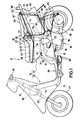
- the motor scooter 11 includes a frame assembly, indicated generally by the reference numeral 12 and which is comprised of a head pipe 13 to which a main tube 14 having a goose neck configuration is affixed, as by welding.
- a pair of side tubes 15 are affixed at their forward ends, as by welding, to the lower central portion of the main tube 14 and curve upwardly and extend rearwardly.
- a power unit, indicated generally by the reference numeral 16 is supported beneath these frame members 15 on a pivot bolt 17.
- the power unit 16 includes an internal combustion engine having a combined crankcase transmission assembly 18 and one or more forwardly inclined cylinders 19.
- a cylinder head assembly 21 is affixed to the cylinder block 19 in a known manner.
- the engine of the power unit 16 is provided with an induction system that includes a carburetor 22 that draws air through a side and rearwardly positioned air cleaner silencer assembly 23. Since the construction of the power unit 16 per se forms no part of the invention, a further description of it is believed to be unnecessary to permit those skilled in the art to understand the construction and operation of the invention.
- a front wheel 24 is rotatably journaled in a suitable manner at the lower end of a front fork 25.
- the front fork 25 is, in turn, dirigibly supported by the head tube 13 in a known manner and carries a pair of handlebars 26 at its upper end by which the front wheel 24 may be steered.
- the engine crankcase transmission assembly 18 drives a variable belt transmission contained within a casing 26 which, in turn, drives a rear wheel 27 that is journaled for rotation by this casing 26.
- the power unit 16 is pivotally mounted on the frame assembly 12 by means of the pivot pin 17. This pivotal movement is restrained by a pair of combined spring and shock absorber assemblies 28 that are interposed between the casing 26 and the frame assembly 12 for suspension travel of the rear wheel 27.
- a fender 29 is affixed to the casing 26 and thus travels with the wheel 27 during its suspension movement.
- Each combined spring shock absorber assembly 28 is fixed at its upper end by means of a bracket 31 to a frame member 32 that extends at each side back from the frame members 15.
- An upstanding frame member 33 extends from the rear ends of the frame members 32.
- a body cover indicated generally by the reference numeral 34 encloses at least in part the frame assembly 12 and some of the running components thus far described.
- This body cover 34 includes a front portion 35 that encloses a battery 36 carried by the front of the frame assembly 12, the head pipe 13 and a portion of the front fork 25.
- This portion 35 also forms a leg shield for the feet of a rider which can be positioned on a platform 36 formed at the rear end of the portion 35.
- the body cover 34 also includes a rear portion 37 that encloses the frame members 15 and a portion of the power unit 16.
- a fuel tank 38 is carried by the frame assembly 12 and specifically by the frame members 15 on brackets 39 and elastic isolators 41.
- the fuel tank 38 extends over the power unit 16 and specifically its forward end and has a rearwardly and sidewardly disposed filler neck 42 to which a detachable cap 43 is affixed.
- the fuel tank 38 is formed from a pair of sheet metal stampings including a lower member 44 and an upper member 45 that are connected to each other by means of peripheral flanges.
- the filler neck 42 is connected to the upper member 45.
- a seat assembly is mounted on the frame assembly 12, in a manner to be described, for accommodating an operator and, if desired, a single passenger.
- This seat 46 is of a two piece construction and includes a front portion 47 and a rear portion 48.
- the front seat portion 47 is disposed immediately behind the foot area 36 and has sufficient length so as to accommodate not only the operator but also so as to fully overlie the fuel tank 38.
- the seat portion 47 is comprised of a relatively rigid backing piece 49 to which a foam or other cushion stuffing material 51 is affixed.
- a covering 52 overlies this cushioning 51 and has downwardly depending skirt portions 53 that terminate in flaps 54 that are affixed to the backing 49 in a suitable manner, as by an adhesive.
- a seat lock 53 depends from the seat 47 and specifically the backing piece 49 and is interlocked into openings (not shown) in a bracket that is affixed to an upstanding frame member 54 so as to detachably affix the front seat portion 47 to the frame 12.
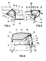
- a cut out 55 is formed at the rear of the seat 47 and at the one side where the fill neck 42 is located.
- This cut out 55 shows in most detail in Figures 4 through 6.
- a plate 56 is affixed to the lower portion of the seat backing piece 49 adjacent the cut out 55 and carries an overflow receptacle 57 that has a trap portion 58 which, in turn, will receive any fuel that may overflow the filler neck 42.
- This accumulated fuel is then drained through a drain tube 59 which terminates at a low portion in the scooter 11 and preferably at a point below the cylinder block 19.
- the receptacle 57 further defines an opening 61 that is generally coextensive with the cut out 55.
- a closure member 62 is provided for selectively closing the opening 61 and cut out 55 when fuel is not being added.
- the closure member 62 is pivotally journaled for movement between its closed and open positions by means of a hinge assembly 63 which, in turn, is connected to a plate 64 that is affixed to the leading side of the receptacle 57.
- a keeper 65 is affixed to the opposite edge of the receptacle 57 on the opposite side of the opening 61 and a slidable latch member 66 carried by the closure 62 cooperates with the keeper 65 so as to hold the closure 62 in its closed position as shown in the figures.
- the closure 62 may be pivoted to an open position as shown in phantom in Figure 5 for accessing the fill neck 42 and cap 43.
- the rear seat portion 48 has a construction generally similar to that of the front seat portion 47, although the configuration is different. That is, the rear seat portion 48 is comprised of a lower backing piece 67 to which a padding material 68 such as a foamed plastic is affixed. A covering 69 having side portions 71 overlies the cushioning material 68 and has flaps 71 that overlie and are affixed to the backing piece 67 in a suitable manner.
- the forward edge of the rear seat 68 is curved and fits into a curved recess formed in the rear portion of the front seat 47 so that when the seat portions 47 and 48 are in their normal position, it provides a neat and continuous appearing surface. This curvature is shown by the line L in Figure 2.
- the rear seat portion 48 is pivotally connected to the frame assembly 12 by means of a hinge assembly 72 that is affixed to the upper end of the frame member 33. In its normal closed position, the front of the seat 48 is supported on the frame member 54 by means of a pair of elastic stops 73 ( Figures 1 and 3).
- the reason for pivotally supporting the rear seat 48 is that it provides a closure for a carrier receptacle, indicated generally by the reference numeral 74 and which is positioned therebeneath within the body covering portion 37.
- the receptacle 74 may be formed from a rigid plastic and has a double wall construction comprised of an inner member 75 and an outer member 76 ( Figure 7).
- the members 75 and 76 define an upstanding wall having an opening at its upper end that is defined by a flange 78 ( Figure 8) to which a sealing gasket 79 is affixed.
- the gasket 79 is adapted to be engaged by a corresponding gasket 81 affixed to the underside of the seat backing member 67 so as to provide a watertight seal for its internal cavity.
- the opening 78 is inclined to the horizontal so as to provide a relatively large opening even though the seat portion 48 has a relatively short length.
- the lower wall of the enclosure 74 has a somewhat dome shaped configuration, as indicated at 82 in Figure 3 so as to afford clearance for the suspension movement of the rear fender 29.
- a grab rail 83 having a cross piece 84 is affixed to the rear body covering portion 37 so as to provide a gripping area for a passenger seated on the rear seat 48.
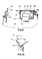
- FIG. 8 and 9 show one such embodiment. This embodiment is, except for the latching mechanism and its operator, the same as the embodiment of Figures 1 through 7 and, for that reason, components which are the same as the previously described embodiment have been identified by the same reference numerals and will not be described again.
- a fixed keeper member 101 is affixed to the inner end of the closure member 62 in the area where the latch 66 of the previous embodiment was positioned.
- a slidable plunger 102 is received within and supported by a plate 103 that is affixed to the receptacle 57 and which is connected to one arm of a bell crank 104.
- the bell crank 104 is pivoted from its latched position as shown in Figure 9 to its released position as shown in phantom lines in this figure by a bowden wire cable 105.
- the bowden wire cable 105 extends through the frame assembly along the frame tubes as shown in Figure 8 to a pivotally supported operator 106 that is contained within a recess 107 formed at an upper portion of the body portion 35.
- a pivotally supported operator 106 that is contained within a recess 107 formed at an upper portion of the body portion 35.
- the hinge 63 may incorporate an integral spring assembly so that the closure member 62 will swing to its opened position when the sliding latch 102 is actuated.
- a similar latch operator 151 may be mounted at the rear of the rider's area on the body portion 37 immediately beneath the front edge of the seat 47 as shown in Figure 10 and in the alternative phantom line view in Figure 8. Other locations obviously can be employed for the operator of the closure member latch.
- the closure member 62 for the opening to access the fill neck 42 has been provided in addition to the cap 43 for the fill neck. It should be understood that, if desired, the fill neck cap 43 can be deleted and a closure for the fill neck 42 can be carried directly by the closure door 62. If this is done, the arrangement should be obviously resilient so that the cap carried by the closure member 62 can form a good sealing relationship with the fill neck 42 when the closure 62 is in its closed position.
Landscapes
- Engineering & Computer Science (AREA)
- Mechanical Engineering (AREA)
- Automatic Cycles, And Cycles In General (AREA)
- Cooling, Air Intake And Gas Exhaust, And Fuel Tank Arrangements In Propulsion Units (AREA)
Applications Claiming Priority (2)
| Application Number | Priority Date | Filing Date | Title |
|---|---|---|---|
| JP1161817A JP2918116B2 (ja) | 1989-06-22 | 1989-06-22 | スクータ型自動二,三輪車の燃料供給部構造 |
| JP161817/89 | 1989-06-22 |
Publications (2)
| Publication Number | Publication Date |
|---|---|
| EP0404195A1 true EP0404195A1 (fr) | 1990-12-27 |
| EP0404195B1 EP0404195B1 (fr) | 1994-04-20 |
Family
ID=15742474
Family Applications (1)
| Application Number | Title | Priority Date | Filing Date |
|---|---|---|---|
| EP90111922A Expired - Lifetime EP0404195B1 (fr) | 1989-06-22 | 1990-06-22 | Dispositif de réservoir à carburant pour scooters |
Country Status (4)
| Country | Link |
|---|---|
| US (1) | US5094315A (fr) |
| EP (1) | EP0404195B1 (fr) |
| JP (1) | JP2918116B2 (fr) |
| DE (1) | DE69008249T2 (fr) |
Cited By (15)
| Publication number | Priority date | Publication date | Assignee | Title |
|---|---|---|---|---|
| EP0606927A1 (fr) * | 1990-10-24 | 1994-07-20 | Suzuki Kabushiki Kaisha | Dispositif de réservoir à carburant pour motocycle |
| EP0751063A1 (fr) * | 1995-06-29 | 1997-01-02 | Yamaha Hatsudoki Kabushiki Kaisha | Carrosserie de véhicule, notamment pour une motocyclette |
| EP1162135A3 (fr) * | 2000-06-09 | 2005-05-11 | Honda Giken Kogyo Kabushiki Kaisha | Motocyclette du type scooter |
| WO2006120830A1 (fr) * | 2005-05-11 | 2006-11-16 | Honda Motor Co., Ltd. | Motocyclette |
| EP1939077A1 (fr) * | 2006-12-27 | 2008-07-02 | HONDA MOTOR CO., Ltd. | Motocyclette |
| EP2036809A1 (fr) * | 2007-09-14 | 2009-03-18 | Yamaha Hatsudoki Kabushiki Kaisha | Véhicule de type à enfourcher |
| WO2010004044A1 (fr) * | 2008-07-11 | 2010-01-14 | Huf Hülsbeck & Fürst Gmbh & Co. Kg | Système de sécurité associé à un bouchon de réservoir |
| EP2128006A4 (fr) * | 2007-02-22 | 2010-12-01 | Yamaha Motor Co Ltd | Véhicule de type à conduite à califourchon |
| EP2130751A4 (fr) * | 2007-03-30 | 2010-12-01 | Yamaha Motor Co Ltd | Véhicule du type à conduite à califourchon |
| CN103171694A (zh) * | 2011-12-20 | 2013-06-26 | 铃木株式会社 | 摩托车的过滤罐布置结构 |
| CN101423079B (zh) * | 2007-10-31 | 2013-09-11 | 雅马哈发动机株式会社 | 摩托车 |
| CN105377682A (zh) * | 2014-01-31 | 2016-03-02 | 雅马哈发动机株式会社 | 车辆 |
| CN105377683A (zh) * | 2014-01-31 | 2016-03-02 | 雅马哈发动机株式会社 | 车辆 |
| EP3363725A1 (fr) * | 2017-02-17 | 2018-08-22 | Yamaha Hatsudoki Kabushiki Kaisha | Véhicule à enfourcher |
| US20250242758A1 (en) * | 2024-01-29 | 2025-07-31 | Bombardier Recreational Products, Inc. | Vehicle drop-down storage area |
Families Citing this family (40)
| Publication number | Priority date | Publication date | Assignee | Title |
|---|---|---|---|---|
| DE4102714C2 (de) * | 1990-01-31 | 1995-06-14 | Suzuki Co Ltd | Elektrische Anlage für ein Motorrad |
| TW265311B (fr) * | 1992-12-18 | 1995-12-11 | Suzuki Co Ltd | |
| WO1995000395A1 (fr) * | 1993-06-25 | 1995-01-05 | Patrick John Galloway | Dispositif destine a l'application de materiaux en feuille |
| US5928535A (en) * | 1997-05-08 | 1999-07-27 | Miller Electric Manufacturing Co. | Fuel tank filler assembly for engine driven welder |
| JP3795200B2 (ja) * | 1997-09-14 | 2006-07-12 | 本田技研工業株式会社 | 自動二輪車のパワーユニット |
| JP3816210B2 (ja) * | 1997-09-30 | 2006-08-30 | 本田技研工業株式会社 | 低床式自動二輪車の車体構造 |
| US6155648A (en) * | 1998-08-31 | 2000-12-05 | Wacker Corporation | Power buggy |
| TW446664B (en) * | 1999-05-25 | 2001-07-21 | Honda Motor Co Ltd | Scooter type motorcycle |
| JP4058874B2 (ja) * | 2000-02-07 | 2008-03-12 | スズキ株式会社 | スクータ型自動二輪車 |
| US6263926B1 (en) | 2000-04-17 | 2001-07-24 | Lincoln Global, Inc. | Fuel assembly for an engine welder |
| JP3879437B2 (ja) * | 2000-06-23 | 2007-02-14 | スズキ株式会社 | 自動二輪車の物品収納装置 |
| US20040079573A1 (en) * | 2001-04-24 | 2004-04-29 | Suzuki Motor Corporation | Motorcycle and storage box arrangement thereof |
| JP4274759B2 (ja) * | 2002-08-16 | 2009-06-10 | ヤマハ発動機株式会社 | 電動二輪車 |
| US7331418B2 (en) * | 2003-03-07 | 2008-02-19 | Bombardier Recreational Products Inc. | Retractable passenger seat for an ATV |
| US7008014B1 (en) * | 2003-07-14 | 2006-03-07 | Polaris Industries Inc. | Adjustable storage seat for recreation and utility vehicles |
| JP2005178629A (ja) * | 2003-12-19 | 2005-07-07 | Yamaha Motor Co Ltd | 燃料キャップ構造 |
| US7188645B2 (en) * | 2003-12-24 | 2007-03-13 | Lincoln Global, Inc. | Visual fuel system for an engine welder |
| JP4451140B2 (ja) * | 2004-01-20 | 2010-04-14 | 本田技研工業株式会社 | 車両におけるロック解除操作部材配設構造 |
| US7380872B2 (en) * | 2004-06-18 | 2008-06-03 | Yamaha Hatsudoki Kabushiki Kaisha | Wheeled vehicle with covers |
| JP2006036013A (ja) * | 2004-07-27 | 2006-02-09 | Yamaha Motor Co Ltd | 自動二輪車 |
| JP2006315503A (ja) * | 2005-05-11 | 2006-11-24 | Honda Motor Co Ltd | 自動二輪車の燃料タンク及び収納ボックスの配置構造 |
| JP4767603B2 (ja) * | 2005-07-04 | 2011-09-07 | ヤマハ発動機株式会社 | パワーユニット及び該パワーユニットを備えた鞍乗型車両 |
| JP2007062609A (ja) * | 2005-08-31 | 2007-03-15 | Honda Motor Co Ltd | 不整地走行車両 |
| JP2007118628A (ja) * | 2005-10-24 | 2007-05-17 | Yamaha Motor Co Ltd | 鞍乗型車両 |
| JP2007210486A (ja) * | 2006-02-10 | 2007-08-23 | Yamaha Motor Co Ltd | 自動二輪車 |
| JP2008162516A (ja) * | 2006-12-28 | 2008-07-17 | Yamaha Motor Co Ltd | 鞍乗型車両 |
| JP2010229840A (ja) * | 2009-03-26 | 2010-10-14 | Honda Motor Co Ltd | 自動二輪車 |
| JP2011073610A (ja) * | 2009-09-30 | 2011-04-14 | Honda Motor Co Ltd | 鞍乗り車両用ユーテイリテイボックスの構造 |
| US8505592B2 (en) * | 2010-09-20 | 2013-08-13 | Honda Motor Company, Ltd. | Fuel spill tray |
| JP5723664B2 (ja) * | 2010-11-22 | 2015-05-27 | 本田技研工業株式会社 | 車両用シート構造 |
| JP5718699B2 (ja) * | 2011-03-25 | 2015-05-13 | 本田技研工業株式会社 | 鞍乗型車両のシート構造 |
| US20130002001A1 (en) * | 2011-06-28 | 2013-01-03 | Weber Aircraft Llc | Retractable armrest |
| JP6018861B2 (ja) * | 2012-09-20 | 2016-11-02 | 本田技研工業株式会社 | 鞍乗型車両 |
| JP5782424B2 (ja) * | 2012-12-13 | 2015-09-24 | 本田技研工業株式会社 | 鞍乗り型車両の後部構造 |
| JP6249726B2 (ja) * | 2013-11-11 | 2017-12-20 | テイ・エス テック株式会社 | 乗り物用シート |
| EP3124364B1 (fr) * | 2014-03-24 | 2019-05-08 | Yamaha Hatsudoki Kabushiki Kaisha | Véhicule de type à selle |
| ES2727622T3 (es) * | 2014-03-24 | 2019-10-17 | Yamaha Motor Co Ltd | Vehículo de montar a horcajadas |
| JP2016008021A (ja) * | 2014-06-26 | 2016-01-18 | ヤマハ発動機株式会社 | 車両 |
| JP6830499B2 (ja) * | 2019-01-31 | 2021-02-17 | 本田技研工業株式会社 | 鞍乗型車両の給油口構造 |
| JP6855517B2 (ja) * | 2019-01-31 | 2021-04-07 | 本田技研工業株式会社 | 鞍乗型車両の給油口構造 |
Citations (4)
| Publication number | Priority date | Publication date | Assignee | Title |
|---|---|---|---|---|
| US4618019A (en) * | 1984-02-17 | 1986-10-21 | Honda Giken Kogyo Kabushiki Kaisha | Motorcycle |
| US4653762A (en) * | 1984-12-27 | 1987-03-31 | Honda Giken Kogyo Kabushiki Kaisha | Fuel tank and fuel feed system for a motorcycle |
| US4721178A (en) * | 1985-08-08 | 1988-01-26 | Honda Giken Kogyo Kabushiki Kaisha | Multi-wheeled vehicle |
| US4813511A (en) * | 1985-06-25 | 1989-03-21 | Honda Giken Kogyo Kabushiki Kaisha | Motorcycle |
Family Cites Families (14)
| Publication number | Priority date | Publication date | Assignee | Title |
|---|---|---|---|---|
| GB819690A (en) * | 1956-03-30 | 1959-09-09 | Innocenti Soc Generale | Improvements in or relating to motor-cycles |
| JPS5144532A (ja) * | 1974-10-15 | 1976-04-16 | Hodogaya Chemical Co Ltd | Donokokushokueki |
| US4036768A (en) * | 1976-06-14 | 1977-07-19 | Texaco Inc. | Polymethacrylate and lube composition thereof |
| FR2436865A1 (fr) * | 1978-09-22 | 1980-04-18 | Renault | Dispositif de condamnation a distance de trappe a essence |
| US4413700A (en) * | 1980-09-17 | 1983-11-08 | Honda Giken Kogyo Kabushiki Kaisha | Seat mounting structure for motorcycles and associated methods |
| JPS58156422A (ja) * | 1982-03-10 | 1983-09-17 | 「あ」谷 豊 | 自動車における給油口自動開閉装置 |
| JPS58179289A (ja) * | 1982-04-14 | 1983-10-20 | Mitsubishi Heavy Ind Ltd | 石炭の液化方法 |
| JPS59154480A (ja) * | 1983-02-23 | 1984-09-03 | Canon Inc | 定着装置 |
| JPS59154480U (ja) * | 1983-04-02 | 1984-10-17 | 本田技研工業株式会社 | 自動二輪車の燃料給油装置 |
| JPH0825491B2 (ja) * | 1985-02-20 | 1996-03-13 | ヤマハ発動機株式会社 | スク−タの収納装置 |
| JPS61196187U (fr) * | 1985-05-29 | 1986-12-06 | ||
| JPS6350787A (ja) * | 1986-08-20 | 1988-03-03 | 株式会社日立製作所 | 燃料集合体 |
| JPS6382823A (ja) * | 1986-09-25 | 1988-04-13 | Honda Motor Co Ltd | 自動車のフユエルキヤツプアダプタのドレン構造 |
| DE3702903A1 (de) * | 1987-01-31 | 1988-08-11 | Porsche Ag | Klappe zum verschliessen einer karosseriemulde |
-
1989
- 1989-06-22 JP JP1161817A patent/JP2918116B2/ja not_active Expired - Fee Related
-
1990
- 1990-06-21 US US07/541,840 patent/US5094315A/en not_active Expired - Lifetime
- 1990-06-22 EP EP90111922A patent/EP0404195B1/fr not_active Expired - Lifetime
- 1990-06-22 DE DE69008249T patent/DE69008249T2/de not_active Expired - Fee Related
Patent Citations (4)
| Publication number | Priority date | Publication date | Assignee | Title |
|---|---|---|---|---|
| US4618019A (en) * | 1984-02-17 | 1986-10-21 | Honda Giken Kogyo Kabushiki Kaisha | Motorcycle |
| US4653762A (en) * | 1984-12-27 | 1987-03-31 | Honda Giken Kogyo Kabushiki Kaisha | Fuel tank and fuel feed system for a motorcycle |
| US4813511A (en) * | 1985-06-25 | 1989-03-21 | Honda Giken Kogyo Kabushiki Kaisha | Motorcycle |
| US4721178A (en) * | 1985-08-08 | 1988-01-26 | Honda Giken Kogyo Kabushiki Kaisha | Multi-wheeled vehicle |
Cited By (21)
| Publication number | Priority date | Publication date | Assignee | Title |
|---|---|---|---|---|
| EP0482610B1 (fr) * | 1990-10-24 | 1996-02-21 | Suzuki Kabushiki Kaisha | Dispositif de réservoir à carburant pour motocycle |
| EP0606927A1 (fr) * | 1990-10-24 | 1994-07-20 | Suzuki Kabushiki Kaisha | Dispositif de réservoir à carburant pour motocycle |
| EP0751063A1 (fr) * | 1995-06-29 | 1997-01-02 | Yamaha Hatsudoki Kabushiki Kaisha | Carrosserie de véhicule, notamment pour une motocyclette |
| CN1073036C (zh) * | 1995-06-29 | 2001-10-17 | 雅马哈发动机株式会社 | 摩托车车体侧部处理结构 |
| EP1162135A3 (fr) * | 2000-06-09 | 2005-05-11 | Honda Giken Kogyo Kabushiki Kaisha | Motocyclette du type scooter |
| WO2006120830A1 (fr) * | 2005-05-11 | 2006-11-16 | Honda Motor Co., Ltd. | Motocyclette |
| EP1939077A1 (fr) * | 2006-12-27 | 2008-07-02 | HONDA MOTOR CO., Ltd. | Motocyclette |
| EP2128006A4 (fr) * | 2007-02-22 | 2010-12-01 | Yamaha Motor Co Ltd | Véhicule de type à conduite à califourchon |
| EP2130751A4 (fr) * | 2007-03-30 | 2010-12-01 | Yamaha Motor Co Ltd | Véhicule du type à conduite à califourchon |
| EP2036809A1 (fr) * | 2007-09-14 | 2009-03-18 | Yamaha Hatsudoki Kabushiki Kaisha | Véhicule de type à enfourcher |
| CN101423079B (zh) * | 2007-10-31 | 2013-09-11 | 雅马哈发动机株式会社 | 摩托车 |
| WO2010004044A1 (fr) * | 2008-07-11 | 2010-01-14 | Huf Hülsbeck & Fürst Gmbh & Co. Kg | Système de sécurité associé à un bouchon de réservoir |
| CN103171694A (zh) * | 2011-12-20 | 2013-06-26 | 铃木株式会社 | 摩托车的过滤罐布置结构 |
| EP2607677A1 (fr) * | 2011-12-20 | 2013-06-26 | Suzuki Motor Corporation | Structure d'agencement de cartouche filtrante de motocyclette |
| CN103171694B (zh) * | 2011-12-20 | 2016-08-31 | 铃木株式会社 | 摩托车的过滤罐布置结构 |
| CN105377682A (zh) * | 2014-01-31 | 2016-03-02 | 雅马哈发动机株式会社 | 车辆 |
| CN105377683A (zh) * | 2014-01-31 | 2016-03-02 | 雅马哈发动机株式会社 | 车辆 |
| CN105377683B (zh) * | 2014-01-31 | 2018-04-03 | 雅马哈发动机株式会社 | 车辆 |
| CN105377682B (zh) * | 2014-01-31 | 2018-04-03 | 雅马哈发动机株式会社 | 车辆 |
| EP3363725A1 (fr) * | 2017-02-17 | 2018-08-22 | Yamaha Hatsudoki Kabushiki Kaisha | Véhicule à enfourcher |
| US20250242758A1 (en) * | 2024-01-29 | 2025-07-31 | Bombardier Recreational Products, Inc. | Vehicle drop-down storage area |
Also Published As
| Publication number | Publication date |
|---|---|
| EP0404195B1 (fr) | 1994-04-20 |
| DE69008249D1 (de) | 1994-05-26 |
| US5094315A (en) | 1992-03-10 |
| DE69008249T2 (de) | 1994-08-04 |
| JPH0325091A (ja) | 1991-02-01 |
| JP2918116B2 (ja) | 1999-07-12 |
Similar Documents
| Publication | Publication Date | Title |
|---|---|---|
| US5094315A (en) | Fuel tank arrangement for scooter | |
| JP2775273B2 (ja) | 自動二輪車 | |
| US4964483A (en) | Motor scooter | |
| US5044646A (en) | Scooter type vehicle | |
| EP0255254B1 (fr) | Véhicule du type moto | |
| US4413700A (en) | Seat mounting structure for motorcycles and associated methods | |
| EP0404194A1 (fr) | Dispositif de stockage pour scooters | |
| EP1524177A2 (fr) | Appareil de commande à distance d'un véhicule du type scooter | |
| EP0323908B1 (fr) | Scooter | |
| JP3610760B2 (ja) | スクータ型車両のフューエルリッド装置 | |
| AU615214B2 (en) | Motor scooter | |
| KR950000751Y1 (ko) | 루우프가 붙은 자동 2륜차 | |
| JPH0659863B2 (ja) | スク−タ型車輛 | |
| JPH0818586B2 (ja) | スクータ型車輌 | |
| JPH0781648A (ja) | 自動二輪車 | |
| JP2552221B2 (ja) | スクータ型車両のヘルメット収納箱装置 | |
| JP2807818B2 (ja) | 小型車両 | |
| JP2552203B2 (ja) | スクータ型車両の物入れ装置 | |
| JPH01202589A (ja) | スクータ型車輌 | |
| JPH07110625B2 (ja) | スク−タ型車輛の物入れ装置 | |
| JP2529779Y2 (ja) | スクータ型車両の収納ボックス装置 | |
| EP0139380A1 (fr) | Goulotte de remplissage d'essence pour véhicule automobile | |
| JP2694337B2 (ja) | スクータ型車両 | |
| JPH0789473A (ja) | 自動二輪車の物品収納構造 | |
| JP2850241B2 (ja) | 自動2輪車 |
Legal Events
| Date | Code | Title | Description |
|---|---|---|---|
| PUAI | Public reference made under article 153(3) epc to a published international application that has entered the european phase |
Free format text: ORIGINAL CODE: 0009012 |
|
| AK | Designated contracting states |
Kind code of ref document: A1 Designated state(s): DE ES FR IT |
|
| 17P | Request for examination filed |
Effective date: 19910327 |
|
| 17Q | First examination report despatched |
Effective date: 19920921 |
|
| GRAA | (expected) grant |
Free format text: ORIGINAL CODE: 0009210 |
|
| AK | Designated contracting states |
Kind code of ref document: B1 Designated state(s): DE ES FR IT |
|
| PG25 | Lapsed in a contracting state [announced via postgrant information from national office to epo] |
Ref country code: IT Free format text: LAPSE BECAUSE OF FAILURE TO SUBMIT A TRANSLATION OF THE DESCRIPTION OR TO PAY THE FEE WITHIN THE PRE;WARNING: LAPSES OF ITALIAN PATENTS WITH EFFECTIVE DATE BEFORE 2007 MAY HAVE OCCURRED AT ANY TIME BEFORE 2007. THE CORRECT EFFECTIVE DATE MAY BE DIFFERENT FROM THE ONE RECORDED.SCRIBED TIME-LIMIT Effective date: 19940420 Ref country code: ES Free format text: THE PATENT HAS BEEN ANNULLED BY A DECISION OF A NATIONAL AUTHORITY Effective date: 19940420 |
|
| REF | Corresponds to: |
Ref document number: 69008249 Country of ref document: DE Date of ref document: 19940526 |
|
| ET | Fr: translation filed | ||
| PLBE | No opposition filed within time limit |
Free format text: ORIGINAL CODE: 0009261 |
|
| STAA | Information on the status of an ep patent application or granted ep patent |
Free format text: STATUS: NO OPPOSITION FILED WITHIN TIME LIMIT |
|
| 26N | No opposition filed | ||
| PGFP | Annual fee paid to national office [announced via postgrant information from national office to epo] |
Ref country code: FR Payment date: 20060608 Year of fee payment: 17 |
|
| PGFP | Annual fee paid to national office [announced via postgrant information from national office to epo] |
Ref country code: DE Payment date: 20060615 Year of fee payment: 17 |
|
| REG | Reference to a national code |
Ref country code: FR Ref legal event code: ST Effective date: 20080229 |
|
| PG25 | Lapsed in a contracting state [announced via postgrant information from national office to epo] |
Ref country code: DE Free format text: LAPSE BECAUSE OF NON-PAYMENT OF DUE FEES Effective date: 20080101 |
|
| PG25 | Lapsed in a contracting state [announced via postgrant information from national office to epo] |
Ref country code: FR Free format text: LAPSE BECAUSE OF NON-PAYMENT OF DUE FEES Effective date: 20070702 |