EP0418182A1 - Dispositif de coulée continue de produits métalliques minces entre cylindres - Google Patents
Dispositif de coulée continue de produits métalliques minces entre cylindres Download PDFInfo
- Publication number
- EP0418182A1 EP0418182A1 EP90470047A EP90470047A EP0418182A1 EP 0418182 A1 EP0418182 A1 EP 0418182A1 EP 90470047 A EP90470047 A EP 90470047A EP 90470047 A EP90470047 A EP 90470047A EP 0418182 A1 EP0418182 A1 EP 0418182A1
- Authority
- EP
- European Patent Office
- Prior art keywords
- counterweight
- cylinders
- walls
- installation
- rolls
- Prior art date
- Legal status (The legal status is an assumption and is not a legal conclusion. Google has not performed a legal analysis and makes no representation as to the accuracy of the status listed.)
- Granted
Links
- 238000009434 installation Methods 0.000 title claims abstract description 12
- 238000009749 continuous casting Methods 0.000 title claims abstract description 8
- 208000029152 Small face Diseases 0.000 claims abstract description 13
- 238000005266 casting Methods 0.000 claims abstract description 10
- 239000011819 refractory material Substances 0.000 claims abstract description 7
- 229910001338 liquidmetal Inorganic materials 0.000 claims description 15
- 238000009413 insulation Methods 0.000 claims 1
- 239000002184 metal Substances 0.000 abstract description 13
- 239000000047 product Substances 0.000 description 7
- VYPSYNLAJGMNEJ-UHFFFAOYSA-N Silicium dioxide Chemical compound O=[Si]=O VYPSYNLAJGMNEJ-UHFFFAOYSA-N 0.000 description 4
- 239000007788 liquid Substances 0.000 description 3
- 239000000463 material Substances 0.000 description 3
- 230000005499 meniscus Effects 0.000 description 3
- 230000015572 biosynthetic process Effects 0.000 description 2
- 230000008595 infiltration Effects 0.000 description 2
- 238000001764 infiltration Methods 0.000 description 2
- 239000000377 silicon dioxide Substances 0.000 description 2
- 238000007711 solidification Methods 0.000 description 2
- 230000008023 solidification Effects 0.000 description 2
- 229910000831 Steel Inorganic materials 0.000 description 1
- 238000001816 cooling Methods 0.000 description 1
- 230000007547 defect Effects 0.000 description 1
- 230000006866 deterioration Effects 0.000 description 1
- 239000006260 foam Substances 0.000 description 1
- 239000012535 impurity Substances 0.000 description 1
- 238000000034 method Methods 0.000 description 1
- 238000000465 moulding Methods 0.000 description 1
- 238000013021 overheating Methods 0.000 description 1
- 238000007789 sealing Methods 0.000 description 1
- 230000035939 shock Effects 0.000 description 1
- 239000012265 solid product Substances 0.000 description 1
- 239000010959 steel Substances 0.000 description 1
Images
Classifications
-
- B—PERFORMING OPERATIONS; TRANSPORTING
- B22—CASTING; POWDER METALLURGY
- B22D—CASTING OF METALS; CASTING OF OTHER SUBSTANCES BY THE SAME PROCESSES OR DEVICES
- B22D11/00—Continuous casting of metals, i.e. casting in indefinite lengths
- B22D11/06—Continuous casting of metals, i.e. casting in indefinite lengths into moulds with travelling walls, e.g. with rolls, plates, belts, caterpillars
- B22D11/0637—Accessories therefor
- B22D11/064—Accessories therefor for supplying molten metal
Definitions
- the invention relates to the continuous casting of thin metallic products, in particular steel, between cylinders.
- the liquid metal is poured into the casting space defined by the portions of the cylindrical walls of the cylinders situated above the plane passing through the parallel axes of said cylinders, and by sealing end walls, also called small faces or side walls.
- the liquid metal gradually solidifies on contact with the cooled cylindrical walls of the cylinders, forming solidified skins which are driven by the rotating cylinders and meet at the neck, that is to say at the said level. plane passing through the axes of the cylinders, to form the finished product which is continuously extracted downwards.
- these installations also include a kind of fixed extension consisting of two longitudinal walls in sealed contact with the cylinders and two front walls extending upwards said small faces or forming an integral part thereof.
- This enhancement will hereinafter be designated by the term “feeder” by analogy with the part surmounting the ingot mold or the mold and intended to contain the withdrawal feeder in the casting installations in fixed ingot mold or molding.
- This "flyweight” has the particular function, in the case of casting between cylinders, of delimiting the cylinder surface on which the solidification of the cast metal takes place, and thus ensuring the regularity of this solidification, whatever the level of the metal in the counterweight.
- the meniscus of the liquid metal is no longer in contact with the walls of the cylinders, the risk of entrainment of impurities floating on the meniscus is thus considerably reduced.
- This counterweight is proposed in a refractory material with high heat insulating properties which, as is known, are therefore not compatible with a high mechanical resistance of the walls of the counterweight. In certain cases, such as the use of a liquid metal supply nozzle equipped with lateral outlets oriented towards the walls of the counterweight, this mechanical resistance may be insufficient in the areas most stressed by the liquid metal currents.
- the object of the invention is to provide a counterweight compatible with the use of a nozzle with lateral outlets and having satisfactory thermal properties.
- the subject of the invention is an installation for continuous casting of thin metallic products between cylinders cooled in rotation, of the type comprising a counterweight cooperating with the cylinders and the small faces to define the casting space, characterized in that the longitudinal walls of the counterweight in contact with the cylinders consist of a refractory with high insulating properties, and in that the front walls of the counterweight in contact with the small faces consist of a refractory with high mechanical resistance.
- the invention consists in using, to constitute the front walls of the counterweight, a refractory capable of withstanding the mechanical stresses undergone by the metal jets coming from the nozzle, this refractory being able to be less insulating than the one forming the longitudinal walls of the counterweight.
- the pouring space delimited by the cylinders, the small faces and the counterweight, is supplied by a nozzle plunging into the liquid metal well, connected to a distributor placed above the machine and containing the liquid metal to be poured.
- this nozzle is straight in shape and has a single opening at its end.
- the metal therefore enters the liquid well in a vertical direction up to a variable depth depending on the geometric characteristics of the machine and the hydrodynamic parameters of its supply.
- the main drawback of such a device is that the liquid metal, shortly after leaving the nozzle, risks licking the cylinders, on which the solidified skin is being formed. On contact with hot metal coming directly from the distributor, the solidified skin partially recovers, which leads to significant risks of rupture of this skin at the center of the cylinders and below.
- a counterweight and a nozzle provided with at least one opening oriented laterally so that the metal entering the casting space does not reach the cylinders until to have circulated in the liquid well and lost much of its overheating and kinetic energy.
- An example of such a nozzle consists of a nozzle with two openings oriented in opposite directions on the same horizontal axis or on two substantially horizontal axes, and emerging inside the counterweight, that is to say above the area where the metal solidifies on the cylinders. In such a device, the metal streams coming from the nozzle will first strike the walls of the counterweight. These must therefore have sufficient mechanical strength.
- the walls of the counterweight are made of a material having good insulating properties, such as silica foam of density 0.5 or 0.75 g / cm3 or an aluminous fibrous refractory. It is, in fact, essential that the refractories in contact with the cylinders be as insulating as possible, because they tend to cool by conduction in the area where this contact takes place. If this cooling is too great, it may result in the formation at this location of a layer of solidified metal which gradually increases. Because of this phenomenon, the constancy of the conditions of arrival of the liquid metal on the cylinders is no longer adequately ensured. In addition, this solidified layer can come off periodically, causing the formation of defects on the product.
- a material having good insulating properties such as silica foam of density 0.5 or 0.75 g / cm3 or an aluminous fibrous refractory.
- the mechanical resistance of these materials is an inverse function of their insulating power. If the walls of the counterweight are subjected to the shock of a flow of liquid metal leaving one of the horizontal openings of the nozzle, there is a significant risk of deterioration of these walls.
- a dense refractory with higher mechanical resistance is used to constitute the front walls of the feeder cooperating with the small faces of the machine.
- the inventors believe that the insulating properties of these front walls are of relatively low importance.
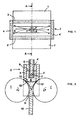
- Figure 2 highlights the vertical arrangement of the machine elements. It shows the liquid metal well 8 whose meniscus 9 is located inside the counterweight 2 and, therefore, above the cylinders 1,1 ′.
- the liquid metal solidifies against the walls of the cylinders 1,1 ′ in opposite rotation and gives rise to a solid product 10.
- the flyweight 2 is in contact on the one hand with the cylinders 1,1 ′ through its walls longitudinal 3,3 ′ in insulating refractory, and on the other hand, with the small lateral faces closing off the casting space (only one of which is visible in FIG. 2), by means of its front walls 4,4 ′ In resistant refractory.
- the nozzle 6 plunges into the liquid well 8 and its openings 7,7 ′ open inside the counterweight 2, that is to say above the upper edges 12 of the small faces 11 and of the lower edges 13,13 ′ Of the longitudinal walls of the counterweight.
- the essential characteristics to take into account for the choice of materials for the counterweight are: - for longitudinal walls, the thermal conductivity, which, measured at 1000 ° C, must be less than 0.5 W / mK - for the front walls, the bulk density which must be greater than 1.5 kg / m3.
- the invention is not limited to the example described and shown.
- the front walls of the counterweight may not be placed on the small faces, but be integral parts of these.
- the pouring nozzle can have a shape and a number of openings other than those of the example, the main thing being that it does not direct a flow of metal at high speed towards the longitudinal walls. insulating weights.
- the method is applicable to weights of variable dimensions used on machines whose cylinders can be moved along their axes, in order to vary the width of the cast product.
Landscapes
- Engineering & Computer Science (AREA)
- Mechanical Engineering (AREA)
- Continuous Casting (AREA)
- Manufacture Of Alloys Or Alloy Compounds (AREA)
- Tunnel Furnaces (AREA)
- Rollers For Roller Conveyors For Transfer (AREA)
- Rolls And Other Rotary Bodies (AREA)
- Reduction Rolling/Reduction Stand/Operation Of Reduction Machine (AREA)
- Cylinder Crankcases Of Internal Combustion Engines (AREA)
- Treatment Of Steel In Its Molten State (AREA)
Abstract
Description
- L'invention concerne la coulée continue des produits métalliques minces, notamment en acier, entre cylindres.
- Dans les installations de coulée continue entre cylindres envisagées jusqu'ici, le métal liquide est déversé dans l' espace de coulée défini par les portions des parois cylindriques des cylindres situées au-dessus du plan passant par les axes parallèles desdits cylindres, et par des parois d'extrémités assurant l'étanchéité, encore appelées petites faces ou parois latérales. Lors de la coulée, le métal liquide se solidifie progressivement au contact des parois cylindriques refroidies des cylindres en formant des peaux solidifiées qui sont entraînées par les cylindres en rotation et se rejoignent au niveau du col, c'est-à-dire au niveau dudit plan passant par les axes des cylindres, pour former le produit fini qui est extrait en continu vers le bas.
- Dans certains cas (voir notamment les documents JP 57-32852 et JP 58-68460), ces installations comportent également une sorte de rehausse fixe constituée de deux parois longitudinales en contact étanche avec les cylindres et de deux parois frontales prolongeant vers le haut lesdites petites faces ou faisant partie intégrante de celles-ci. Cette rehausse sera par la suite désignée par le terme de "masselotte" par analogie avec la partie surmontant la lingotière ou le moule et destinée à contenir la masselotte de retrait dans les installations de coulée en lingotière fixe ou de moulage. Cette "masselotte" a notamment pour fonction, dans le cas de la coulée entre cylindres, de délimiter la surface de cylindre sur laquelle s'effectue la solidification du métal coulé, et ainsi d'assurer la régularité de cette solidification, quel que soit le niveau du métal dans la masselotte. De plus, le ménisque du métal liquide n'étant plus en contact avec les parois des cylindres, le risque d'entraînement des impuretés flottant sur le ménisque est ainsi considérablement réduit.
- Cette masselotte est proposée en un matériau réfractaire à hautes propriétés isolantes de la chaleur qui de ce fait, comme on le sait, ne sont pas compatibles avec une résistance mécanique élevée des parois de la masselotte. Dans certains cas, comme l'utilisation d'une busette d'alimentation en métal liquide équipée de sorties latérales orientées vers les parois de la masselotte, cette résistance mécanique peut être insuffisante dans les zones les plus sollicitées par les courants de métal liquide.
- Le but de l'invention est de proposer une masselotte compatible avec l'utilisation d'une busette à sorties latérales et présentant des propriétés thermiques satisfaisantes.
- A cet effet, l'invention a pour objet une installation de coulée continue de produits métalliques minces entre cylindres refroidis en rotation, du type comportant une masselotte coopérant avec les cylindres et les petites faces pour définir l'espace de coulée, caractérisée en ce que les parois longitudinales de la masselotte en contact avec les cylindres sont constituées d'un réfractaire à propriétés isolantes élevées, et en ce que les parois frontales de la masselotte en contact avec les petites faces sont constituées d'un réfractaire à résistance mécanique élevée.
- Comme on l'aura compris, l'invention consiste à utiliser, pour constituer les parois frontales de la masselotte, un réfractaire pouvant résister aux sollicitations mécaniques subies de la part des jets de métal issus de la busette, ce réfractaire pouvant être moins isolant que celui formant les parois longitudinales de la masselotte.
- L'espace de coulée, délimité par les cylindres, les petites faces et la masselotte, est alimenté par une busette plongeant dans le puits de métal liquide, connectée à un répartiteur placé au-dessus de la machine et contenant le métal liquide à couler. Dans le cas le plus simple, cette busette est de forme droite et comporte une ouverture unique à son extrémité. Le métal pénètre donc dans le puits liquide selon une direction verticale jusqu 'à une profondeur variable en fonction des caractéristiques géométriques de la machine et des paramètres hydrodynamiques de son alimentation. Le principal inconvénient d'un tel dispositif est que le métal liquide, peu de temps après sa sortie de la busette, risque de venir lécher les cylindres, sur lesquels la peau solidifiée est en formation. Au contact du métal chaud en provenance directe du répartiteur, la peau solidifée refond partiellement, ce qui entraîne d'importants risques de rupture de cette peau au niveau de l'entraxe des cylindres et en dessous.
- Ce problème peut être résolu par l'utilisation conjuguée d'une masselotte et d'une busette munie d'au moins une ouverture orientée latéralement de manière à ce que le métal pénétrant dans l'espace de coulée ne parvienne sur les cylindres qu'après avoir circulé dans le puits liquide et perdu une grande partie de sa surchauffe et de son énergie cinétique. Un exemple d'une telle busette consiste en une busette à deux ouvertures orientées dans des directions opposées sur un même axe horizontal ou sur deux axes sensiblement horizontaux, et débouchant à l'intérieur de la masselotte, c'est-à-dire au-dessus de la zone où le métal se solidifie sur les cylindres. Dans un tel dispositif, les flots de métal issus de la busette vont d'abord frapper les parois de la masselotte. Celles-ci doivent donc présenter une résistance mécanique suffisante.
- Habituellement toutes les parois de la masselotte sont réalisées en un matériau présentant de bonnes propriétés isolantes, telle que la mousse de silice de densité 0,5 ou 0,75 g/cm3 ou un réfractaire fibreux alumineux. Il est, en effet, indispensable que les réfractaires en contact avec les cylindres soient aussi isolants que possible, car ils ont tendance à se refroidir par conduction dans la zone où a lieu ce contact. Si ce refroidissement est trop important, il peut en résulter la formation à cet endroit d'une couche de métal solidifé qui croît progressivement. A cause de ce phénomène, la constance des conditions d'arrivée du métal liquide sur les cylindres n'est plus convenablement assurée. De plus, cette couche solidifiée peut se détacher périodiquement, entraînant la formation de défauts sur le produit.
- Or, comme on l'a dit, la résistance mécanique de ces matériaux est une fonction inverse de leur pouvoir isolant. Si les parois de la masselotte subissent le choc d'un flot de métal liquide sortant de l'une des ouvertures horizontales de la busette, il y a un risque important de détérioration de ces parois.
- Selon l'invention, on utilise pour constituer les parois frontales de la masselote coopérant avec les petites faces de la machine un réfractaire dense à plus forte résistance mécanique. En effet les inventeurs estiment que les propriétés isolantes de ces parois frontales n'ont qu'une importance relativement faible. En utilisant un réfactaire compact, tel que de la silice, ou un béton alumineux, on rend l'utilisation de la masselotte compatible avec celle d'une busette équipée de deux sorties latérales, si ces sorties orientent les jets de métal en direction des parois frontales résistantes.
- L'invention sera mieux comprise au vu de la description qui suit, faisant référence à la planche unique de dessins annexée, sur laquelle :
- - la figure 1 montre schématiquement, vus de dessus, les cylindres, la busette de coulée et la masselotte d'une installation de coulée continue de produits métalliques minces selon l'invention.
- - la figure 2 est une coupe selon l'axe A-A de la figure 1. Sur la figure 1, les cylindres 1,1′ d'une machine de coulée continue de produits métalliques minces sont surmontés par une masselotte 2, composée de quatre parois. Les parois longitudinales 3,3′ sont en contact avec les cylindres et sont orientées selon une direction sensiblement parallèle à l'axe des cylindres. Elles sont réalisées en un matériau réfractaire à propriétés isolantes élevées. les parois frontales 4,4′ sont posées de façon étanche sur les petites faces (non visibles sur la figure 1) qui obturent latéralement l'espace de coulée 5 délimité par les cylindres. Le jeu entre les parois de la masselotte doit être aussi réduit que possible (de préférence inférieur à 1/10 mm) afin d'éviter les infiltrations de métal liquide. La busette 6, alimentant la machine en métal liquide et reliée à un répartiteur non représenté, est munie de deux ouvertures latérales tournées chacune vers une des parois frontales 4,4′ de la masselotte et orientant les écoulements de métal préférentiellement sur ces parois 4,4′, comme indiqué par les flèches.
- La figure 2 met en évidence la disposition verticale des éléments de la machine. Elle montre le puits de métal liquide 8 dont le ménisque 9 est situé à l'intérieur de la masselotte 2 et, donc, au dessus des cylindres 1,1′. Le métal liquide se solidifie contre les parois des cylindres 1,1′ en rotation opposée et donne naissance à un produit solide 10. La masselotte 2 est en contact d'une part avec les cylindres 1,1′ par l'intermédiaire de ses parois longitudinales 3,3′ en réfractaire isolant, et d'autre part, avec les petites faces latérales obturant l'espace de coulée (dont une seule 11 est visible sur la figure 2), par l'intermédiaire de ses parois frontales 4,4′ en réfractaire résistant. La busette 6 plonge dans le puits liquide 8 et ses ouvertures 7,7′ débouchent à l'intérieur de la masselotte 2, c'est-à-dire au dessus des bords supérieurs 12 des petites faces 11 et des arêtes inférieures 13,13′ des parois longitudinales de la masselotte.
- Les caractéristiques essentielles à prendre en compte pour le choix des matériaux de la masselotte sont :
- pour les parois longitudinales, la conductivité thermique, qui, mesurée à 1 000°C, doit être inférieure à 0,5 W/m.K.
- pour les parois frontales, la densité apparente qui doit être supérieure à 1,5 kg/m³. - Bien entendu, l'invention n'est pas limitée à l'exemple décrit et représenté. En particulier, les parois frontales de la masselotte peuvent ne pas être posées sur les petites faces, mais être des parties intégrantes de celles-ci. D'autre part, la busette de coulée peut avoir une forme et un nombre d'ouvertures autres que ceux de l'exemple, l'essentiel étant qu'elle n'oriente pas d'écoulement à grande vitesse du métal vers les parois longitudinales isolantes de la masselotte. Enfin, le procédé est applicable aux masselottes de dimensions variables utilisée sur les machines dont les cylindres peuvent être déplacés selon leurs axes, afin de faire varier la largeur du produit coulé.
Claims (4)
Priority Applications (1)
| Application Number | Priority Date | Filing Date | Title |
|---|---|---|---|
| AT90470047T ATE95734T1 (de) | 1989-09-06 | 1990-08-20 | Vorrichtung zum stranggiessen von duennen metallischen produkten zwischen zylindern. |
Applications Claiming Priority (2)
| Application Number | Priority Date | Filing Date | Title |
|---|---|---|---|
| FR8911737 | 1989-09-06 | ||
| FR8911737A FR2651455B1 (fr) | 1989-09-06 | 1989-09-06 | Dispositif de coulee continue de produits metalliques minces entre cylindres. |
Publications (2)
| Publication Number | Publication Date |
|---|---|
| EP0418182A1 true EP0418182A1 (fr) | 1991-03-20 |
| EP0418182B1 EP0418182B1 (fr) | 1993-10-13 |
Family
ID=9385236
Family Applications (1)
| Application Number | Title | Priority Date | Filing Date |
|---|---|---|---|
| EP90470047A Expired - Lifetime EP0418182B1 (fr) | 1989-09-06 | 1990-08-20 | Dispositif de coulée continue de produits métalliques minces entre cylindres |
Country Status (23)
| Country | Link |
|---|---|
| US (1) | US5092391A (fr) |
| EP (1) | EP0418182B1 (fr) |
| JP (1) | JPH0399758A (fr) |
| KR (1) | KR910005949A (fr) |
| CN (1) | CN1022295C (fr) |
| AT (1) | ATE95734T1 (fr) |
| AU (1) | AU633347B2 (fr) |
| BR (1) | BR9004425A (fr) |
| CA (1) | CA2024676A1 (fr) |
| CS (1) | CS424690A2 (fr) |
| DD (1) | DD297580A5 (fr) |
| DE (1) | DE69003917T2 (fr) |
| DK (1) | DK0418182T3 (fr) |
| ES (1) | ES2045873T3 (fr) |
| FI (1) | FI90743C (fr) |
| FR (1) | FR2651455B1 (fr) |
| HU (1) | HU208268B (fr) |
| IE (1) | IE903215A1 (fr) |
| NO (1) | NO903849L (fr) |
| PL (1) | PL286771A1 (fr) |
| PT (1) | PT95221A (fr) |
| RU (1) | RU1836180C (fr) |
| ZA (1) | ZA907060B (fr) |
Cited By (1)
| Publication number | Priority date | Publication date | Assignee | Title |
|---|---|---|---|---|
| EP0593383A1 (fr) * | 1992-10-16 | 1994-04-20 | Usinor Sacilor | Dispositif de coulée continue entre cylindres de produits métalliques minces |
Families Citing this family (1)
| Publication number | Priority date | Publication date | Assignee | Title |
|---|---|---|---|---|
| ITMI20031356A1 (it) * | 2003-07-02 | 2005-01-03 | Danieli Off Mecc | Dispositivo di alimentazione di metallo fuso in cristallizzatore. |
Family Cites Families (6)
| Publication number | Priority date | Publication date | Assignee | Title |
|---|---|---|---|---|
| JPS58176059A (ja) * | 1982-04-07 | 1983-10-15 | Hitachi Zosen Corp | ツインモ−ルドロ−ラ連続鋳造設備における鋳片引き抜き法 |
| JPS6021170A (ja) * | 1983-07-15 | 1985-02-02 | Nisshin Steel Co Ltd | 連続鋳造用ノズル |
| JPS6021171A (ja) * | 1983-07-16 | 1985-02-02 | Nisshin Steel Co Ltd | 幅広薄板連続鋳造装置 |
| JPS6076256A (ja) * | 1983-09-30 | 1985-04-30 | Hitachi Zosen Corp | ツインモ−ルドロ−ラ形連続鋳造設備における鋳型 |
| JP2528284B2 (ja) * | 1986-07-04 | 1996-08-28 | 横浜ゴム株式会社 | タイヤトレッド用ゴム組成物 |
| JPS63126646A (ja) * | 1986-11-17 | 1988-05-30 | Nippon Mining Co Ltd | 双ロ−ル式連続鋳造用ダム |
-
1989
- 1989-09-06 FR FR8911737A patent/FR2651455B1/fr not_active Expired - Lifetime
-
1990
- 1990-08-16 HU HU905043A patent/HU208268B/hu not_active IP Right Cessation
- 1990-08-20 DK DK90470047.3T patent/DK0418182T3/da active
- 1990-08-20 ES ES90470047T patent/ES2045873T3/es not_active Expired - Lifetime
- 1990-08-20 AT AT90470047T patent/ATE95734T1/de not_active IP Right Cessation
- 1990-08-20 EP EP90470047A patent/EP0418182B1/fr not_active Expired - Lifetime
- 1990-08-20 DE DE90470047T patent/DE69003917T2/de not_active Expired - Fee Related
- 1990-08-23 AU AU61282/90A patent/AU633347B2/en not_active Ceased
- 1990-08-25 KR KR1019900013187A patent/KR910005949A/ko not_active Withdrawn
- 1990-08-31 CS CS904246A patent/CS424690A2/cs unknown
- 1990-09-03 FI FI904339A patent/FI90743C/fi active IP Right Grant
- 1990-09-04 IE IE321590A patent/IE903215A1/en unknown
- 1990-09-04 NO NO90903849A patent/NO903849L/no unknown
- 1990-09-05 DD DD90343818A patent/DD297580A5/de not_active IP Right Cessation
- 1990-09-05 PT PT95221A patent/PT95221A/pt not_active Application Discontinuation
- 1990-09-05 RU SU904830917A patent/RU1836180C/ru active
- 1990-09-05 CA CA002024676A patent/CA2024676A1/fr not_active Abandoned
- 1990-09-05 ZA ZA907060A patent/ZA907060B/xx unknown
- 1990-09-05 CN CN90107454A patent/CN1022295C/zh not_active Expired - Fee Related
- 1990-09-05 US US07/577,867 patent/US5092391A/en not_active Expired - Fee Related
- 1990-09-05 BR BR909004425A patent/BR9004425A/pt unknown
- 1990-09-05 JP JP2235467A patent/JPH0399758A/ja active Pending
- 1990-09-06 PL PL28677190A patent/PL286771A1/xx unknown
Non-Patent Citations (5)
| Title |
|---|
| PATENT ABSTRACTS OF JAPAN, vol. 12, no. 376 (M-750)[3223], 7 octobre 1988; & JP-A-63 126 646 (NIPPON MINING CO., LTD) 30-08-1988 * |
| PATENT ABSTRACTS OF JAPAN, vol. 8, no. 12 (M-269)[1449], 19 janvier 1984; & JP-A-58 176 059 (HITACHI ZOSEN K.K.) 15-10-1983 * |
| PATENT ABSTRACTS OF JAPAN, vol. 9, no. 142 (M-388)[1865], 18 juin 1985; & JP-A-60 021 170 (MITSUSHIN SEIKOU K.K.) 02-02-1985 * |
| PATENT ABSTRACTS OF JAPAN, vol. 9, no. 142 (M-388)[1865], 18 juin 1985; & JP-A-60 021 171 (MITSUSHIN SEIKOU K.K.) 02-02-1985 * |
| PATENT ABSTRACTS OF JAPAN, vol. 9, no. 215 (M-409)[1938], 3 septembre 1985; & JP-A-60 076 256 (HITACHI ZOSEN K.K.) 30-04-1985 * |
Cited By (2)
| Publication number | Priority date | Publication date | Assignee | Title |
|---|---|---|---|---|
| EP0593383A1 (fr) * | 1992-10-16 | 1994-04-20 | Usinor Sacilor | Dispositif de coulée continue entre cylindres de produits métalliques minces |
| FR2696960A1 (fr) * | 1992-10-16 | 1994-04-22 | Usinor Sacilor | Dispositif de coulée continue entre cylindres de produits métalliques minces. |
Also Published As
| Publication number | Publication date |
|---|---|
| FI90743B (fi) | 1993-12-15 |
| AU6128290A (en) | 1991-03-14 |
| HU208268B (en) | 1993-09-28 |
| BR9004425A (pt) | 1991-09-10 |
| FI904339A0 (fi) | 1990-09-03 |
| DE69003917T2 (de) | 1994-04-07 |
| CN1022295C (zh) | 1993-10-06 |
| JPH0399758A (ja) | 1991-04-24 |
| EP0418182B1 (fr) | 1993-10-13 |
| PT95221A (pt) | 1992-05-29 |
| FI90743C (fi) | 1994-03-25 |
| CN1049990A (zh) | 1991-03-20 |
| DK0418182T3 (da) | 1994-02-21 |
| RU1836180C (ru) | 1993-08-23 |
| ATE95734T1 (de) | 1993-10-15 |
| FR2651455A1 (fr) | 1991-03-08 |
| CA2024676A1 (fr) | 1991-03-07 |
| PL286771A1 (en) | 1991-03-11 |
| HUT57101A (en) | 1991-11-28 |
| ES2045873T3 (es) | 1994-01-16 |
| NO903849D0 (no) | 1990-09-04 |
| US5092391A (en) | 1992-03-03 |
| KR910005949A (ko) | 1991-04-27 |
| CS424690A2 (en) | 1991-11-12 |
| DD297580A5 (de) | 1992-01-16 |
| FR2651455B1 (fr) | 1992-05-22 |
| AU633347B2 (en) | 1993-01-28 |
| DE69003917D1 (de) | 1993-11-18 |
| NO903849L (no) | 1991-03-07 |
| ZA907060B (en) | 1992-04-29 |
| HU905043D0 (en) | 1991-01-28 |
| IE903215A1 (en) | 1991-03-13 |
Similar Documents
| Publication | Publication Date | Title |
|---|---|---|
| EP0418182B1 (fr) | Dispositif de coulée continue de produits métalliques minces entre cylindres | |
| EP0743114B1 (fr) | Procédé de lubrification des parois d'une lingotière de coulée continue des métaux et lingotière pour sa mise en oeuvre | |
| EP0270418B1 (fr) | Bouchon de retenue des scories et procédé pour sa mise en oeuvre et sa fabrication | |
| CA2258109C (fr) | Lingotiere de coulee continue pour la coulee continue en charge verticale des metaux | |
| EP0242347A2 (fr) | Dispositif pour la coulée d'un métal en phase pâteuse | |
| FR2619032A3 (fr) | Procede et dispositif d'alimentation en metal liquide d'une installation de coulee continue de produits minces en lingotiere a parois mobiles | |
| FR2704786A3 (fr) | Procédé de coulée continue en charge des métaux, notamment de l'acier, et lingotière pour sa mise en Óoeuvre. | |
| EP0160635A2 (fr) | Procédé et dispositif pour la lubrification d'une lingotière de coulée continue | |
| EP4061557B1 (fr) | Moule de fonderie, procédé de fabrication du moule et procédé de fonderie | |
| FR2525131A1 (fr) | Procede et dispositif de fabrication d'un lingot d'acier creux | |
| EP0868952B1 (fr) | Lingotière de coulée continue de métaux | |
| BE701099A (fr) | ||
| EP0911096B1 (fr) | Busette de coulée pour installation de coulée continue des métaux, notamment de coulée entre cylindres | |
| FR2703278A1 (fr) | Procédé et dispositif de réalisation d'une enveloppe métallique sur une âme de forme allongée. | |
| WO2000037197A1 (fr) | Lingotiere pluriangulaire de coulee continue en charge d'un produit metallurgique | |
| FR2868346A1 (fr) | Moule pour la coulee d'un metal liquide et procede correspondant | |
| BE893777A (fr) | Perfectionnements aux procedes de coulee continue des metaux, et lingotiere pour la mise en oeuvre de ces procedes | |
| FR2940158A1 (fr) | Procede et systeme de moulage d'une piece metallique de fonderie | |
| FR2711329A1 (fr) | Procédé de moulage de pièces en fonte ou en tout autre métal présentant une température de fusion élevée. | |
| BE485210A (fr) | ||
| BE354789A (fr) | ||
| BE906039A (fr) | Dispositif et procede pour la coulee d'un metal en phase pateuse. | |
| BE501355A (fr) | ||
| FR2569360A1 (fr) | Lingotiere pour coulee continue de produits plats de faible epaisseur |
Legal Events
| Date | Code | Title | Description |
|---|---|---|---|
| PUAI | Public reference made under article 153(3) epc to a published international application that has entered the european phase |
Free format text: ORIGINAL CODE: 0009012 |
|
| AK | Designated contracting states |
Kind code of ref document: A1 Designated state(s): AT BE CH DE DK ES GB GR IT LI LU NL SE |
|
| 17P | Request for examination filed |
Effective date: 19910830 |
|
| 17Q | First examination report despatched |
Effective date: 19930208 |
|
| GRAA | (expected) grant |
Free format text: ORIGINAL CODE: 0009210 |
|
| AK | Designated contracting states |
Kind code of ref document: B1 Designated state(s): AT BE CH DE DK ES GB GR IT LI LU NL SE |
|
| REF | Corresponds to: |
Ref document number: 95734 Country of ref document: AT Date of ref document: 19931015 Kind code of ref document: T |
|
| REF | Corresponds to: |
Ref document number: 69003917 Country of ref document: DE Date of ref document: 19931118 |
|
| ITF | It: translation for a ep patent filed | ||
| REG | Reference to a national code |
Ref country code: ES Ref legal event code: FG2A Ref document number: 2045873 Country of ref document: ES Kind code of ref document: T3 |
|
| GBT | Gb: translation of ep patent filed (gb section 77(6)(a)/1977) |
Effective date: 19931223 |
|
| REG | Reference to a national code |
Ref country code: GR Ref legal event code: FG4A Free format text: 3009844 |
|
| REG | Reference to a national code |
Ref country code: DK Ref legal event code: T3 |
|
| EPTA | Lu: last paid annual fee | ||
| PLBE | No opposition filed within time limit |
Free format text: ORIGINAL CODE: 0009261 |
|
| STAA | Information on the status of an ep patent application or granted ep patent |
Free format text: STATUS: NO OPPOSITION FILED WITHIN TIME LIMIT |
|
| 26N | No opposition filed | ||
| EAL | Se: european patent in force in sweden |
Ref document number: 90470047.3 |
|
| REG | Reference to a national code |
Ref country code: GB Ref legal event code: IF02 |
|
| PGFP | Annual fee paid to national office [announced via postgrant information from national office to epo] |
Ref country code: GB Payment date: 20040730 Year of fee payment: 15 |
|
| PGFP | Annual fee paid to national office [announced via postgrant information from national office to epo] |
Ref country code: DE Payment date: 20040805 Year of fee payment: 15 |
|
| PGFP | Annual fee paid to national office [announced via postgrant information from national office to epo] |
Ref country code: LU Payment date: 20040806 Year of fee payment: 15 Ref country code: CH Payment date: 20040806 Year of fee payment: 15 |
|
| PGFP | Annual fee paid to national office [announced via postgrant information from national office to epo] |
Ref country code: SE Payment date: 20040809 Year of fee payment: 15 |
|
| PGFP | Annual fee paid to national office [announced via postgrant information from national office to epo] |
Ref country code: DK Payment date: 20040810 Year of fee payment: 15 Ref country code: AT Payment date: 20040810 Year of fee payment: 15 |
|
| PGFP | Annual fee paid to national office [announced via postgrant information from national office to epo] |
Ref country code: NL Payment date: 20040818 Year of fee payment: 15 Ref country code: ES Payment date: 20040818 Year of fee payment: 15 |
|
| PGFP | Annual fee paid to national office [announced via postgrant information from national office to epo] |
Ref country code: GR Payment date: 20040827 Year of fee payment: 15 |
|
| PGFP | Annual fee paid to national office [announced via postgrant information from national office to epo] |
Ref country code: BE Payment date: 20040902 Year of fee payment: 15 |
|
| PG25 | Lapsed in a contracting state [announced via postgrant information from national office to epo] |
Ref country code: LU Free format text: LAPSE BECAUSE OF NON-PAYMENT OF DUE FEES Effective date: 20050820 Ref country code: IT Free format text: LAPSE BECAUSE OF NON-PAYMENT OF DUE FEES;WARNING: LAPSES OF ITALIAN PATENTS WITH EFFECTIVE DATE BEFORE 2007 MAY HAVE OCCURRED AT ANY TIME BEFORE 2007. THE CORRECT EFFECTIVE DATE MAY BE DIFFERENT FROM THE ONE RECORDED. Effective date: 20050820 Ref country code: GB Free format text: LAPSE BECAUSE OF NON-PAYMENT OF DUE FEES Effective date: 20050820 Ref country code: AT Free format text: LAPSE BECAUSE OF NON-PAYMENT OF DUE FEES Effective date: 20050820 |
|
| PG25 | Lapsed in a contracting state [announced via postgrant information from national office to epo] |
Ref country code: SE Free format text: LAPSE BECAUSE OF NON-PAYMENT OF DUE FEES Effective date: 20050821 |
|
| PG25 | Lapsed in a contracting state [announced via postgrant information from national office to epo] |
Ref country code: ES Free format text: LAPSE BECAUSE OF NON-PAYMENT OF DUE FEES Effective date: 20050822 |
|
| PG25 | Lapsed in a contracting state [announced via postgrant information from national office to epo] |
Ref country code: LI Free format text: LAPSE BECAUSE OF NON-PAYMENT OF DUE FEES Effective date: 20050831 Ref country code: DK Free format text: LAPSE BECAUSE OF NON-PAYMENT OF DUE FEES Effective date: 20050831 Ref country code: CH Free format text: LAPSE BECAUSE OF NON-PAYMENT OF DUE FEES Effective date: 20050831 Ref country code: BE Free format text: LAPSE BECAUSE OF NON-PAYMENT OF DUE FEES Effective date: 20050831 |
|
| PG25 | Lapsed in a contracting state [announced via postgrant information from national office to epo] |
Ref country code: NL Free format text: LAPSE BECAUSE OF NON-PAYMENT OF DUE FEES Effective date: 20060301 Ref country code: DE Free format text: LAPSE BECAUSE OF NON-PAYMENT OF DUE FEES Effective date: 20060301 |
|
| PG25 | Lapsed in a contracting state [announced via postgrant information from national office to epo] |
Ref country code: GR Free format text: LAPSE BECAUSE OF NON-PAYMENT OF DUE FEES Effective date: 20060302 |
|
| REG | Reference to a national code |
Ref country code: CH Ref legal event code: PL |
|
| REG | Reference to a national code |
Ref country code: DK Ref legal event code: EBP |
|
| EUG | Se: european patent has lapsed | ||
| GBPC | Gb: european patent ceased through non-payment of renewal fee |
Effective date: 20050820 |
|
| NLV4 | Nl: lapsed or anulled due to non-payment of the annual fee |
Effective date: 20060301 |
|
| REG | Reference to a national code |
Ref country code: ES Ref legal event code: FD2A Effective date: 20050822 |
|
| BERE | Be: lapsed |
Owner name: S.A. *USINOR SACILOR Effective date: 20050831 |