EP0434414B1 - Halterung für integrierte Schaltung - Google Patents
Halterung für integrierte Schaltung Download PDFInfo
- Publication number
- EP0434414B1 EP0434414B1 EP90313963A EP90313963A EP0434414B1 EP 0434414 B1 EP0434414 B1 EP 0434414B1 EP 90313963 A EP90313963 A EP 90313963A EP 90313963 A EP90313963 A EP 90313963A EP 0434414 B1 EP0434414 B1 EP 0434414B1
- Authority
- EP
- European Patent Office
- Prior art keywords
- portions
- shafts
- cover
- shaft
- recess
- Prior art date
- Legal status (The legal status is an assumption and is not a legal conclusion. Google has not performed a legal analysis and makes no representation as to the accuracy of the status listed.)
- Expired - Lifetime
Links
Images




Classifications
-
- H—ELECTRICITY
- H10—SEMICONDUCTOR DEVICES; ELECTRIC SOLID-STATE DEVICES NOT OTHERWISE PROVIDED FOR
- H10P—GENERIC PROCESSES OR APPARATUS FOR THE MANUFACTURE OR TREATMENT OF DEVICES COVERED BY CLASS H10
- H10P72/00—Handling or holding of wafers, substrates or devices during manufacture or treatment thereof
- H10P72/10—Handling or holding of wafers, substrates or devices during manufacture or treatment thereof using carriers specially adapted therefor, e.g. front opening unified pods [FOUP]
- H10P72/19—Handling or holding of wafers, substrates or devices during manufacture or treatment thereof using carriers specially adapted therefor, e.g. front opening unified pods [FOUP] closed carriers
- H10P72/1904—Handling or holding of wafers, substrates or devices during manufacture or treatment thereof using carriers specially adapted therefor, e.g. front opening unified pods [FOUP] closed carriers specially adapted for containing chips, dies or ICs
-
- H—ELECTRICITY
- H05—ELECTRIC TECHNIQUES NOT OTHERWISE PROVIDED FOR
- H05K—PRINTED CIRCUITS; CASINGS OR CONSTRUCTIONAL DETAILS OF ELECTRIC APPARATUS; MANUFACTURE OF ASSEMBLAGES OF ELECTRICAL COMPONENTS
- H05K7/00—Constructional details common to different types of electric apparatus
- H05K7/02—Arrangements of circuit components or wiring on supporting structure
- H05K7/10—Plug-in assemblages of components, e.g. IC sockets
- H05K7/1053—Plug-in assemblages of components, e.g. IC sockets having interior leads
- H05K7/1061—Plug-in assemblages of components, e.g. IC sockets having interior leads co-operating by abutting
- H05K7/1069—Plug-in assemblages of components, e.g. IC sockets having interior leads co-operating by abutting with spring contact pieces
Definitions
- This invention relates to an IC carrier comprising a base and a cover pivotably attached to the base.
- An IC carrier disclosed in USP4007479 comprises a base, and a cover pivotably connected to the base through an integrally molded hinge. The cover is not removably attached to the base.
- IC carriers disclosed in Japanese Utility Model Early laid-open Publication No. Sho 60-146089 and Japanese Utility Model Publication No. Sho 60-10310 are designed such that a canceled state of the shaft coupling is formed in a position where a cover is attached to a base.
- the latter for example, has such a construction as that the shaft coupling is naturally canceled in a pivotal position where the pivot shaft is fitted to a cut-out portion of a key-groove.
- One of the above-mentioned conventional IC carriers has such a shortcoming as that the cover cannot be attached to and removed from the base, while the other has the advantage that the cover can be removably attached to the base but it has such a shortcoming as that the shaft coupling is naturally canceled in the position where the cover is attached to the base.
- the present invention has been accomplished in view of the above.
- an IC carrier comprising a base and a cover pivotably attached to said base through a shaft coupling, an IC being held by closing said cover relative to said base, one end of said cover being provided with a plurality of shafts forming said shaft coupling and arranged at spaces in a projecting fashion, one end of said base being provided with a plurality of short recess portions shorter than the length of said shafts forming said shaft coupling and a plurality of recess portions equal to or longer than the length of said shafts, said short and long recess portions being arranged at spaces, one ends of said recess portions being provided with shaft inserting portions for receiving tips of said shafts, said cover being able to be bent in the thick direction thereof, said shafts being able to be inclined in accordance with the bending motion of said cover, said shafts corresponding to said long recess portions equal to or longer than the length of said shafts being inserted into said shaft inserting portions at one ends of said reces
- the shafts mounted to the cover are inclined in accordance with the bending motion of the cover in the backward direction and inserted into the shaft inserting portions at one end portions of the short recess portions shorter than the length of the shafts, and then brought into engagement with the recess portions by the restoring motion of the cover to assemble the shaft coupling.
- the shaft coupling can be disassembled by removing the shafts from the shaft inserting portions of the short recess portions shorter than the length of the shafts while bending the cover again in the backward direction.
- the cover cannot be attached to nor removed from the base unless the cover is bent in the backward direction.
- the shaft coupling is undesirably canceled within a range where the cover can be pivoted in a normal state of use.
- the shaft coupling can easily be canceled simply by bending the cover in the backward direction.
- Figs. 1 through 12 show one embodiment of the present invention.
- This embodiment exemplifies a thin and flat IC carrier which is designed for the use of an IC 5 holding an IC chip 4 by serving a film 3 as shown in Fig. 11 as a carrier.
- the IC carrier comprises a base 1 and a cover 2, the base 1 is formed in a square frame plate, an IC accommodating section 6 is defined in an inner area along an opening portion 1a of the frame plate, a frame plate portion forming a bottom plate of the IC accommodating section 6 is served as a supporting plate 7 for supporting a peripheral portion of the IC 5, the supporting plate 7 is provided with pins 9 projecting therefrom and adapted to position the IC 5, and the IC positioning pins 9 are inserted into holes 8 for positioning the IC 5 to hold the IC 5 on the base 1 while loading the IC 5 in the IC accommodating section 6 of the base 1.
- the supporting plate 7 is provided with positioning holes 12 into which carrier positioning pins disposed on the side of an IC socket 10 shown in Fig.
- the cover 2 is formed of a square frame plate, the square frame plate is engaged with the IC accommodating section 6 to press the peripheral portion of the IC 5, and positioning holes 11, into which the IC carrier positioning pins disposed on the side of the IC socket 10 and the IC positioning pins 9 are to be inserted, are formed in a marginal portion along the opening portion 2a of the square frame plate.
- a plurality of shafts 13 and 14 are arranged at one end of the cover 2 at spaces in a projecting fashion.
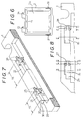
- the shaft 13, as shown in Fig. 6, has a coaxis, and two of such shafts, for example, arranged in such a manner as to be projected in the same direction perpendicular to the pivoting direction of the cover 2.
- a plurality of short recess portions 15 shorter than the length of the shafts forming the shaft coupling and long recess portions 16 equal to or longer than the length of the shafts are formed in one end of the base 1 at spaces in such a manner as to correspond to the shafts 13 and 14, and one ends of the recess portions 15 and 16 are provided with a plurality of shaft inserting portions 17 and 18 for receiving the tips of the shafts 13 and 14.
- the cover 2 can be backwardly bent in the thick direction thereof, and by backwardly bending the cover 2, the shafts 13 and 14 can be inclined in the bending direction of the cover 2.
- the shaft 14 corresponding to the long recess portion 16 longer than the length of the shafts is inserted into the shaft inserting portion 18 at one end of the recess portion 16 via the recess portion 16.
- the shaft 14 corresponding to the long recess portion 16 longer than the length of the shafts is inserted into the shaft inserting portion 18 at one end of the recess portion 16 via the recess portion 16.
- the shaft 13 corresponding to the short recess portion 15 shorter than the length of the shafts is inserted into the shaft inserting portion 17 at one end of the short recess portion 15 shorter than the length of the shafts when the shaft 13 is in its inclined state owing to bending motion of the cover 2 in the backward direction, and by restoring the bending cover 2 to its original state upon completion of the insertion of the shaft 13 as shown in Fig.
- the shaft 13 is engaged in the recess portion 15, and an end face 19 of a basic end portion of the shaft 13 is contacted with the other end 20 (end face on the opposite side with respect to the shaft inserting portion 17) of the recess portion 15 in order to prevent the shafts 13 and 14 from slipping out of the shaft inserting portions 17 and 18.
- the shaft 14 is loosely inserted into the shaft inserting portion 18 within the recess portion 16 with a play formed in the slipping-out direction.
- the shaft inserting portions 17 and 18 are formed in the same construction which is shown in Figs. 9(A) through 9(F).
- the recess portions 15 and 16 are provided with inclined surfaces 21 and 22 formed at entrance portions of the shafts 13 and 14 and adapted to enlarge the entrance portions.
- End portions of the recess portions 15 and 16 at the entrance portions of the shaft inserting portions are provided with arcuate bearing portions for holding arcuate surfaces of the bottom portions of the circular shafts 13 and 14 which are engaged with the recess portions 15 and 16, and also with arcuate bearing portions 25 and 26 for holding upper arcuate surfaces of the shafts 13 and 14 by receiving terminal ends of the shafts 13 and 14 penetrating the bearing portions 23 and 24 as shown in Figs.
- the short recess portion 15 shorter the length of the shaft is connected with an enlarged recess portion 29 longer than the shaft formed at the entrance portion of the shaft 13.
- the enlarged recess portion 29 is long on the opposite side with respect to the shaft inserting portion 17 of the recess portion 15, and a step portion 30 is formed between the recess portion 15 and the enlarged recess portion 29 there. As is shown in Figs.
- the shaft 13 is inclined in accordance with the backward bending motion of the cover 2 and brought into engagement with the enlarged recess portion 29, the tip of the shaft 13, while supporting the basic end of the shaft 13 by the step portion 30, is inclined and inserted into the shaft inserting portion 17, and by restoring the backwardly bending state of the cover 2, the shaft 13 is brought into engagement with the recess portion 15. That is to say, if the step 30, which is necessarily formed at the entrance portion of the recess portion 15, exists, it can be practiced without a provision of the enlarged recess portion 29.
- the recess portions 15 and 16 are opened up on the side of an upper surface of the end portion of the base 1, the cover 2, as shown in Figs. 1, 2 and 10, is backwardly bent in the thick direction thereof in order to be brought into an erected state with respect to the base 1, and in that state, the shafts 13 and 14 are held to the recess portions 15 and 16 to realize the above-mentioned engagement.
- it may be designed such that the recess portions 15 and 16 are opened up on the side of the end faces of the recess portions 15 and 16, and the shafts 13 and 14 are engaged into the recess portions 15 and 16 from the end face side.
- the cover 2 is pivotably mounted to the base 1, a shaft coupling, which is not easily slipped out at any pivoting position is formed, and by closing the cover 2 relative to the base 1, the IC 5 can be held therebetween.
- the cover 2 is engaged in the IC accommodating section 6, engaging projections 31 formed in the vicinity of the free end portion of the both sides of the cover 2 are snap engaged with projections 32 formed on the corresponding both sides of the IC accommodating section 6, thereby to prevent the cover 2 from being accidentally pivoted in the opening direction.
- the carrier carrying the IC 5 is loaded on a table 34, which can be resiliently moved upward and downward, of the socket 10, a contact 35 of the socket 10 is inserted into a contact positioning hole 36, and by intimately contacting the presser plate 37 with the socket 10 to press the base 1, the contact 35 is resiliently contacted with a contacting piece of the IC 5 through the opening portion 2a of the cover 2 as a reaction.
- the cover causes the shafts, while inclining the shafts owing to the backward bending motion of the cover, to be inserted into shaft inserting portions of corresponding short recess portions shorter than the length of the shafts, and the shafts are engaged in the recessed portions by the restoring motion of the cover to enhance an easy assembly of the shaft coupling.
- the shaft coupling can easily be disassembled by removing the shafts from the shaft inserting portions of the short recess portions shorter than the length of the shafts while bending the cover again in the backward direction.
- the cover cannot be inserted into nor removed from the recess portions unless the cover is bent backwardly. Accordingly, there is no such fear as to cause undesirable cancellation of the shaft coupling within a range of a pivotal movement of the cover. If the cover is bent backwardly while exhibiting the above-mentioned effect, cancellation of the shaft coupling can easily be realized.
Landscapes
- Engineering & Computer Science (AREA)
- Microelectronics & Electronic Packaging (AREA)
- Connecting Device With Holders (AREA)
- Packaging Frangible Articles (AREA)
Claims (6)
- Halterung für eine integrierte Schaltung, bestehend aus einem Aufnahmebehälter (1) für die integrierte Schaltung (5) und einem über eine Zapfenlagerung verschwenkbar daran angelenkten, die integrierte Schaltung (5) in Schließlage festlegenden Deckel (2), der entlang einer Kante mit einer Mehrzahl von beabstandeten, über die Kante vorspringenden Lagerzapfen (13, 14) versehen ist und der Aufnahmebehälter (1) dementsprechend in einem Kantenbereich mit dementsprechend beabstandeten Rücksprüngen (15, 16), deren einer (15) kürzer ist als die Lagerzapfen (13, 14) und deren anderer (16) eine Länge aufweist, die gleich oder größer ist als die Länge der Lagerzapfen (13, 14), wobei die Rücksprünge (15, 16) einen Ends in die freie Enden der Lagerzapfen (13, 14) aufnehmende Lagerstellen (17, 18) übergehen, mit einem um eine die idielle Zapfenachse querende Achse biegbaren Deckel (2) mit einhergehender Schrägstellung der Lagerzapfen (13, 14), so daß bei um die die idielle Zapfenachse querende Biegeachse gebogenem Deckel der dem länger ausgelegten Rücksprung (16) zuzuordnende Lagerzapfen (14) anliegend an die von der in diesem Rücksprung (16) ausgebildeten Lagerstelle (18) abgekehrten Wandung des Rücksprungs (16) in den Rücksprung (16) einfügbar ist und der dem kürzer ausgelegten Rücksprung (15) zuzuordnende Lagerzapfen (13) in diesen Rücksprung (15) ebenfalls anliegend an die von der in diesem Rücksprung (15) ausgebildeten Lagerstelle (17) abgekehrte Wandung des Rücksprungs (15) eingefügbar ist und bei Aufhebung der dem Deckel (2) vermittelten Biegung die freien Enden der Lagerzapfen (13, 14) sich in die in den Rücksprüngen (19, 16) ausgebildeten Lagerstellen (17, 18) für die freien Ende der Lagerzapfen (13, 14) einfügen.
- Halterung für eine integrierte Schaltung nach Anspruch 1, dadurch gekennzeichnet, daß der kürzer ausgelegte Rücksprung (15) im Aufnahmebehälter (1) in einem Rücksprung (29) ausgebildet ist, der eine größere Länge aufweist als die Lagerzapfen (13, 14), wobei der Überstand des Rücksprungs (29) über den Rücksprung (15) auf der von der Lagerstelle (17) des Rücksprungs (15) abgekehrten Seite des Rücksprungs (15) ausgebildet ist.
- Halterung für eine integrierte Schaltung nach Anspruch 2, dadurch gekennzeichnet, daß zwischen dem Überstand des Rücksprungs (29) über den darin ausgebildeten Rücksprung (15) eine Stufe (30) ausgebildet ist.
- Halterung für eine intergrierte Schaltung nach einem der Ansprüche 1 bis 3, dadurch gekennzeichnet, daß an den an die Lagerstellen (17, 18) für die freien Enden der Lagerzapfen (13, 14) angrenzenden Wandbereichen der Rücksprünge (15, 16) im Aufnahmebehälter (1) die Lagerzapfen (13, 14) unterfangende Lagerböcke (23, 24) mit einer der Umfangsfläche der Lagerzapfen (13, 14) entsprechenden Lagerfläche angeformt sind.
- Halterung für eine integrierte Schaltung nach einem der Ansprüche 1 bis 4, dadurch gekennzeichnet, daß in den Lagerstellen (17, 18) für die freien Ende der Lagerzapfen (13, 14) gegen den Umfang der freien Enden der Lagerzapfen (13, 14) zur Anlage kommende Stützflächen ausgebildet sind.
- Halterung für eine integrierte Schaltung nach einem der Ansprüche 1 bis 5, dadurch gekennzeichnet, daß die Rücksprünge (15, 16) im Aufnahmebehälter (1) den Zugang zu den Rücksprüngen vergrößernde einfallende Wandungsbereiche (21, 22) aufweisen.
Applications Claiming Priority (3)
| Application Number | Priority Date | Filing Date | Title |
|---|---|---|---|
| JP1333999A JPH0658998B2 (ja) | 1989-12-22 | 1989-12-22 | Icキャリア |
| JP333999/89 | 1989-12-22 | ||
| SG149394A SG149394G (en) | 1989-12-22 | 1994-10-13 | IC carrier |
Publications (2)
| Publication Number | Publication Date |
|---|---|
| EP0434414A1 EP0434414A1 (de) | 1991-06-26 |
| EP0434414B1 true EP0434414B1 (de) | 1994-04-27 |
Family
ID=26574698
Family Applications (1)
| Application Number | Title | Priority Date | Filing Date |
|---|---|---|---|
| EP90313963A Expired - Lifetime EP0434414B1 (de) | 1989-12-22 | 1990-12-19 | Halterung für integrierte Schaltung |
Country Status (5)
| Country | Link |
|---|---|
| US (1) | US5109980A (de) |
| EP (1) | EP0434414B1 (de) |
| JP (1) | JPH0658998B2 (de) |
| DE (1) | DE69008500D1 (de) |
| SG (1) | SG149394G (de) |
Families Citing this family (41)
| Publication number | Priority date | Publication date | Assignee | Title |
|---|---|---|---|---|
| US5485351A (en) * | 1989-06-09 | 1996-01-16 | Labinal Components And Systems, Inc. | Socket assembly for integrated circuit chip package |
| JPH04329279A (ja) * | 1991-04-30 | 1992-11-18 | Yamaichi Electron Co Ltd | 電気部品用ソケット |
| JPH0675416B2 (ja) * | 1991-12-20 | 1994-09-21 | 山一電機株式会社 | 接続器 |
| US5247250A (en) * | 1992-03-27 | 1993-09-21 | Minnesota Mining And Manufacturing Company | Integrated circuit test socket |
| USD350942S (en) | 1992-08-25 | 1994-09-27 | Particle Solutions | Semiconductor wafer support |
| JPH0763082B2 (ja) * | 1993-02-15 | 1995-07-05 | 山一電機株式会社 | Icキャリア |
| JPH07121758B2 (ja) * | 1993-03-12 | 1995-12-25 | 山一電機株式会社 | Icキャリア |
| IT229919Y1 (it) * | 1993-05-19 | 1999-02-05 | Lt Terraneo Spa | Pulsantiera videocitofonica componibile e modulare per cablaggio |
| US5344334A (en) * | 1993-06-11 | 1994-09-06 | The Whitaker Corporation | Hinged cover for an electrical socket |
| FR2707433B1 (fr) * | 1993-07-08 | 1995-08-18 | Pontarlier Connectors | Connecteur pour carte, en particulier pour carte électronique. |
| JP2544084B2 (ja) * | 1993-12-28 | 1996-10-16 | 山一電機株式会社 | 電気部品の接続器 |
| JP2655827B2 (ja) * | 1995-04-17 | 1997-09-24 | 山一電機株式会社 | Icキャリア |
| JP2768920B2 (ja) * | 1995-08-11 | 1998-06-25 | 山一電機株式会社 | Icキャリア |
| US5791914A (en) * | 1995-11-21 | 1998-08-11 | Loranger International Corporation | Electrical socket with floating guide plate |
| US5647750A (en) * | 1995-11-30 | 1997-07-15 | The Whitaker Corporation | Socket for a tape carrier package |
| JP3292038B2 (ja) * | 1996-05-31 | 2002-06-17 | 日産自動車株式会社 | 物入れ |
| US6050442A (en) * | 1996-09-27 | 2000-04-18 | Cascade Engineering, Inc. | Multi-compartment containers, hinged lid and divider assemblies therefor, and hinge assemblies |
| US5762200A (en) * | 1997-07-16 | 1998-06-09 | Eastern Container Companies | Product suspension packing |
| US5969245A (en) * | 1998-05-05 | 1999-10-19 | Primax Electronics Ltd. | Scanner casing |
| TW370324U (en) * | 1998-06-17 | 1999-09-11 | Primax Electronics Ltd | Platform scanner document press |
| USD430024S (en) * | 1998-11-04 | 2000-08-29 | Affymetrix, Inc. | Chip packaging device |
| US6065626A (en) * | 1998-12-08 | 2000-05-23 | Huang; Chien Jung | Box opening/closing structure |
| JP2000180469A (ja) * | 1998-12-18 | 2000-06-30 | Fujitsu Ltd | 半導体装置用コンタクタ及び半導体装置用コンタクタを用いた試験装置及び半導体装置用コンタクタを用いた試験方法及び半導体装置用コンタクタのクリーニング方法 |
| JP2001185306A (ja) * | 1999-12-28 | 2001-07-06 | Jst Mfg Co Ltd | モジュール用コネクタ |
| US6474477B1 (en) | 2001-05-02 | 2002-11-05 | Ching T. Chang | Carrier assembly for semiconductor IC (integrated circuit) packages |
| US6692280B2 (en) * | 2001-09-28 | 2004-02-17 | Intel Corporation | Socket warpage reduction apparatus and method |
| TW549762U (en) * | 2002-07-18 | 2003-08-21 | Benq Corp | Electronic device having electronic card |
| TW549655U (en) * | 2002-12-20 | 2003-08-21 | Hon Hai Prec Ind Co Ltd | An electrical connector |
| TW580207U (en) * | 2003-03-05 | 2004-03-11 | Hon Hai Prec Ind Co Ltd | Electrical connector assembly |
| CN2728014Y (zh) * | 2004-07-02 | 2005-09-21 | 富士康(昆山)电脑接插件有限公司 | 电连接组件 |
| JP5392807B2 (ja) * | 2007-06-05 | 2014-01-22 | サカセ化学工業株式会社 | 電子部品の運搬ケース |
| US7861458B2 (en) * | 2007-12-13 | 2011-01-04 | Rehrig Pacific Company | Collapsible container |
| US8561976B2 (en) * | 2008-03-27 | 2013-10-22 | American Panel Corporation | Transportable carrier compatable with a retractable pin tool |
| CA2809709C (en) * | 2013-03-14 | 2018-02-13 | Cledlight Semiconductor Lighting Co., Ltd. | Rotational mounting for linear led light |
| TW201446101A (zh) * | 2013-05-30 | 2014-12-01 | Hon Hai Prec Ind Co Ltd | 承載裝置 |
| US9717156B2 (en) * | 2015-07-03 | 2017-07-25 | Lotes Co., Ltd | Electrical socket connector with guide frame IC chip placement |
| CA2960500A1 (en) | 2016-03-11 | 2017-09-11 | Rehrig Pacific Company | Collapsible crate with wood appearance |
| US12448172B2 (en) | 2018-03-05 | 2025-10-21 | Rehrig Pacific Company | Collapsible container |
| US11597557B2 (en) | 2018-10-04 | 2023-03-07 | Rehrig Pacific Company | Reconfigurable beverage crate |
| CA3172382A1 (en) | 2021-09-16 | 2023-03-16 | Rehrig Pacific Company | Hybrid collapsible crate |
| EP4479315B1 (de) * | 2022-02-14 | 2026-01-21 | Tanos GmbH | Aufbewahrungseinrichtung |
Family Cites Families (15)
| Publication number | Priority date | Publication date | Assignee | Title |
|---|---|---|---|---|
| US3391383A (en) * | 1966-06-20 | 1968-07-02 | Hughes Aircraft Co | Electrical connector for integrated circuit elements |
| US4007479A (en) * | 1976-03-29 | 1977-02-08 | Honeywell Information Systems, Inc. | Fixture for an integrated circuit chip |
| US4307819A (en) * | 1980-02-28 | 1981-12-29 | Yukio Araki | Box comprising main portion and lid portion pivotably connected to main portion |
| US4477991A (en) * | 1981-12-24 | 1984-10-23 | Polaroid Corporation | Frame for transparency film |
| JPS59135699U (ja) * | 1983-02-28 | 1984-09-10 | 山一電機工業株式会社 | Icソケツトにおけるic押え装置 |
| JPS6010310A (ja) * | 1983-06-29 | 1985-01-19 | Nippon Denshi Kagaku Kk | ロボツト制御装置 |
| JPS60146089A (ja) * | 1984-01-06 | 1985-08-01 | 帝人株式会社 | ぼかし捺染繊維構造物 |
| GB2164213B (en) * | 1984-09-06 | 1988-07-13 | Nec Corp | Structure for connecting leadless chip carrier |
| CA1233305A (en) * | 1984-11-30 | 1988-03-01 | W.S. Dominic Ng | Hinge structure |
| JPH0219421Y2 (de) * | 1984-12-30 | 1990-05-29 | ||
| JPH0237752Y2 (de) * | 1985-05-21 | 1990-10-12 | ||
| JPS61278159A (ja) * | 1985-06-03 | 1986-12-09 | Yamaichi Electric Mfg Co Ltd | Icパツケ−ジ用キヤリア |
| US4663803A (en) * | 1986-04-15 | 1987-05-12 | Menasha Corporation | Security hinge joint with separate hinge pin |
| US4706161A (en) * | 1986-11-17 | 1987-11-10 | Minnesota Mining And Manufacturing Company | Device protective apparatus |
| US4925059A (en) * | 1989-03-20 | 1990-05-15 | International Packaging Corporation | Hinged box construction |
-
1989
- 1989-12-22 JP JP1333999A patent/JPH0658998B2/ja not_active Expired - Fee Related
-
1990
- 1990-12-19 DE DE69008500T patent/DE69008500D1/de not_active Expired - Lifetime
- 1990-12-19 EP EP90313963A patent/EP0434414B1/de not_active Expired - Lifetime
- 1990-12-20 US US07/631,676 patent/US5109980A/en not_active Expired - Lifetime
-
1994
- 1994-10-13 SG SG149394A patent/SG149394G/en unknown
Also Published As
| Publication number | Publication date |
|---|---|
| JPH0658998B2 (ja) | 1994-08-03 |
| EP0434414A1 (de) | 1991-06-26 |
| SG149394G (en) | 1995-03-17 |
| US5109980A (en) | 1992-05-05 |
| JPH03195000A (ja) | 1991-08-26 |
| DE69008500D1 (de) | 1994-06-01 |
Similar Documents
| Publication | Publication Date | Title |
|---|---|---|
| EP0434414A1 (de) | Halterung für integrierte Schaltung | |
| US6890203B2 (en) | Card connector reduced in operating force | |
| KR100225161B1 (ko) | 표면접점부착 카드용 커넥터 | |
| JP2670517B2 (ja) | Icキャリア搭載形ソケットにおける接触機構 | |
| JP4172856B2 (ja) | Icソケット | |
| US6231365B1 (en) | Memory card connector | |
| JPH0565186A (ja) | Icキヤリア又はicソケツト | |
| JPH0237752Y2 (de) | ||
| US6565386B1 (en) | Electrical connector | |
| JPH0217308B2 (de) | ||
| JP2580074Y2 (ja) | フレキシブル基板用電気コネクタ | |
| JPH0454333A (ja) | 回動レバーの取付装置 | |
| CA2032552A1 (en) | Ic carrier | |
| JP2659924B2 (ja) | Icソケット | |
| US5021868A (en) | IC carrier | |
| JPH0353471A (ja) | 電気コネクタ | |
| JPS6258580A (ja) | 回路板コネクタ | |
| KR100216312B1 (ko) | 전기부품용 소켓 | |
| JPS5814209Y2 (ja) | 蓋体ロック部材 | |
| JPH073583Y2 (ja) | エッジコネクタ用コンタクト | |
| JPH0782941A (ja) | 開閉リッド用のロックスプリング | |
| JP3513422B2 (ja) | 携帯用時計 | |
| CN2254238Y (zh) | 电连接器 | |
| KR850000508Y1 (ko) | 시계밴드의 괘지장치 | |
| JPH0733414Y2 (ja) | Icソケット |
Legal Events
| Date | Code | Title | Description |
|---|---|---|---|
| PUAI | Public reference made under article 153(3) epc to a published international application that has entered the european phase |
Free format text: ORIGINAL CODE: 0009012 |
|
| AK | Designated contracting states |
Kind code of ref document: A1 Designated state(s): DE FR GB IT |
|
| 17P | Request for examination filed |
Effective date: 19910910 |
|
| 17Q | First examination report despatched |
Effective date: 19930806 |
|
| GRAA | (expected) grant |
Free format text: ORIGINAL CODE: 0009210 |
|
| AK | Designated contracting states |
Kind code of ref document: B1 Designated state(s): DE FR GB IT |
|
| PG25 | Lapsed in a contracting state [announced via postgrant information from national office to epo] |
Ref country code: DE Effective date: 19940427 |
|
| ET | Fr: translation filed | ||
| REF | Corresponds to: |
Ref document number: 69008500 Country of ref document: DE Date of ref document: 19940601 |
|
| ITF | It: translation for a ep patent filed | ||
| RAP2 | Party data changed (patent owner data changed or rights of a patent transferred) |
Owner name: YAMAICHI ELECTRONICS CO., LTD. |
|
| RAP4 | Party data changed (patent owner data changed or rights of a patent transferred) |
Owner name: YAMAICHI ELECTRONICS CO., LTD. |
|
| PLBE | No opposition filed within time limit |
Free format text: ORIGINAL CODE: 0009261 |
|
| STAA | Information on the status of an ep patent application or granted ep patent |
Free format text: STATUS: NO OPPOSITION FILED WITHIN TIME LIMIT |
|
| 26N | No opposition filed | ||
| PG25 | Lapsed in a contracting state [announced via postgrant information from national office to epo] |
Ref country code: FR Effective date: 19950831 |
|
| REG | Reference to a national code |
Ref country code: FR Ref legal event code: ST |
|
| PGFP | Annual fee paid to national office [announced via postgrant information from national office to epo] |
Ref country code: GB Payment date: 19951211 Year of fee payment: 6 |
|
| PG25 | Lapsed in a contracting state [announced via postgrant information from national office to epo] |
Ref country code: GB Effective date: 19961219 |
|
| GBPC | Gb: european patent ceased through non-payment of renewal fee |
Effective date: 19961219 |
|
| PG25 | Lapsed in a contracting state [announced via postgrant information from national office to epo] |
Ref country code: IT Free format text: LAPSE BECAUSE OF NON-PAYMENT OF DUE FEES Effective date: 20051219 |