EP0448033A2 - Verfahren zur Herstellung eines Magnetkopfes - Google Patents
Verfahren zur Herstellung eines Magnetkopfes Download PDFInfo
- Publication number
- EP0448033A2 EP0448033A2 EP91104227A EP91104227A EP0448033A2 EP 0448033 A2 EP0448033 A2 EP 0448033A2 EP 91104227 A EP91104227 A EP 91104227A EP 91104227 A EP91104227 A EP 91104227A EP 0448033 A2 EP0448033 A2 EP 0448033A2
- Authority
- EP
- European Patent Office
- Prior art keywords
- thin film
- soft magnetic
- magnetic head
- top portion
- ion milling
- Prior art date
- Legal status (The legal status is an assumption and is not a legal conclusion. Google has not performed a legal analysis and makes no representation as to the accuracy of the status listed.)
- Granted
Links
Images





Classifications
-
- G—PHYSICS
- G11—INFORMATION STORAGE
- G11B—INFORMATION STORAGE BASED ON RELATIVE MOVEMENT BETWEEN RECORD CARRIER AND TRANSDUCER
- G11B5/00—Recording by magnetisation or demagnetisation of a record carrier; Reproducing by magnetic means; Record carriers therefor
- G11B5/127—Structure or manufacture of heads, e.g. inductive
- G11B5/1272—Assembling or shaping of elements
-
- G—PHYSICS
- G11—INFORMATION STORAGE
- G11B—INFORMATION STORAGE BASED ON RELATIVE MOVEMENT BETWEEN RECORD CARRIER AND TRANSDUCER
- G11B5/00—Recording by magnetisation or demagnetisation of a record carrier; Reproducing by magnetic means; Record carriers therefor
- G11B5/127—Structure or manufacture of heads, e.g. inductive
- G11B5/187—Structure or manufacture of the surface of the head in physical contact with, or immediately adjacent to the recording medium; Pole pieces; Gap features
- G11B5/1871—Shaping or contouring of the transducing or guiding surface
Definitions
- the present invention relates to a method of manufacturing a magnetic head, and more specifically, it relates to a method of manufacturing a rotary magnetic head used in a system like a VCR (Video Cassette Recorder), an R-DAT and the like.
- VCR Video Cassette Recorder
- a medium having a high coercive force such as a metal tape and the like, has been used as a recording medium.
- a thin film of a soft magnetic alloy having a high saturation magnetic flux density is used as a core material of a magnetic head.
- a magnetic head 20 having a core of the soft magnetic alloy thin film 13 its track width is defined by the thickness of the thin film 13.
- a magnetic head having a track width of 10 ⁇ m or under which offers a higher recording density it is difficult to maintain a sufficient core efficiency of its core because the entire core is formed of the thin film 13, which leads to high magnetic reluctance.
- the inventors of the present invention have proposed that the thickness of a magnetic head core (i.e., thickness of a soft magnetic alloy thin film) should be so designed to be equivalent to a track width in a gap portion while it should be larger than the track width in any portion away from the gap portion.
- Fig. 6 shows a magnetic head 21 disclosed in the above Patent Publication
- Fig. 7 shows a method of manufacturing the same.
- a soft magnetic alloy thin film 23 has a thickness required for a track width in a gap portion 22 while it is thicker in other portions.
- the magnetic head thus structured includes a V-shaped groove 31 formed in a nonmagnetic substrate 27 at a specified pitch.
- a soft magnetic alloy thin film 23 is formed on an inclined side 29 of the groove 31 to have a larger thickness than that required for obtaining a track width of the magnetic head 21; thereafter, a resist pattern 42 is formed covering the soft magnetic alloy thin film 23 except for a top portion 32 of the V-shaped groove, and an exposed portion of the soft magnetic alloy thin film 23 is etched to a thickness required for the track width to obtain a body 43.
- the body 43 is finished into a magnetic head having a tape contact face as shown in Fig. 7(h) by a well-known magnetic head manufacturing process of cutting, shaping, polishing, glass bonding, cylindrical grinding, tape polishing and the like.
- the photoresist can not be uniformly coated on and adhere to the substrate 27 because it does not assume a plane; thus, there arises the problem that the resist pattern has a poor accuracy.
- a magnetic head employing a soft magnetic thin film as a core, in which a track width and a rate of a front core thickness to a back core thickness are controlled depending upon a thickness of a film deposited on a substrate, so that a mechanically strong gap is implemented and a decline of a reproducing sensitivity because of a narrowed track is prevented (see Japanese Unexamined Patent Publication No.
- a magnetic head which is so configured that a track width is smaller in size than a core thickness in order to increase a sectional area of a magnetic metal of a back core, whereby an increase in magnetic reluctance because of a narrowed track width is eased (see Japanese Unexamined Patent Publication No.
- a magnetic head in which a surface portion of a tape sliding face is made simply of a magnetic substance, a track width in a gap portion is determined depending upon a nonmagnetic substance, and a width of a core formed of laminated film of magnetic films and nonmagnetic films is made thicker than the track width in the gap portion, so that a magnetic reluctance of the core is reduced to enhance a reproducing efficiency (see Japanese Unexamined Patent Publication No.
- a method of manufacturing a magnetic head in which a core thickness in a portion other than a portion near a gap is made larger than a track width, so that a magnetic reluctance is reduced to enhance a recording/reproducing efficiency (see Japanese Unexamined Patent Publication No. 235011/1989); and a magnetic head in which a core thickness on the back side is made twice or more as large as a core thickness on the front side, so that a gap and a track are narrowed to improve an electromagnetic transducing property and a recording/reproducing property (see Japanese Unexamined Patent Publication No. 40117/1990).
- the present invention is accomplished to overcome disadvantages of the above mentioned prior arts, and an object thereof is to provide a method of manufacturing a magnetic head in which an ion milling is employed for processing a gap portion of a soft magnetic alloy thin film formed on an inclined side of a V-shaped groove in a nonmagnetic substrate and a self shadowing effect of the top portion of the V-shaped groove is utilized.
- the present invention provides a method of manufacturing a magnetic head comprising the steps of forming a plurality of almost V-shaped parallel grooves in a surface of a substrate; forming a soft magnetic thin film larger in thickness than that required for a track width on one wall of each of the grooves; processing the soft magnetic thin film at the top portion of the groove walls to a thickness required for the track width by ion milling utilizing a self-shadowing effect of the top portion of the groove walls; filling the grooves with nonmagnetic substance; and performing a finishing process required for completing a magnetic head including the steps of cutting, shaping, polishing, bonding, etc.
- an ion milling is employed for processing a soft magnetic thin film on the top portion of a wall surface of each groove to be a gap portion; this means the directions of incident beams contributing to the milling are uniform.
- a self shadowing effect of the top of the wall surface of each groove is utilized in performing the ion milling to process the soft magnetic alloy thin film; therefore, there is no need of the step of forming a resist pattern.
- a soft magnetic alloy thin film is an FeAlSi alloy thin film, while a nonmagnetic substrate is made of crystalline glass.
- a soft magnetic alloy thin film for example, an NiFe alloy thin film, an FeSiGa alloy thin film, a CoNbZr alloy thin film or the like may be used; as the nonmagnetic substrate, a ceramics substrate may be used.
- the material of the substrate is appropriately determined in accordance with an agreement in thermal expansion with a soft magnetic material and an abrasion characteristic.
- nonmagnetic substance with which the grooves of the substrate is filled preferably used are those having substantially the same abrasion as the substrate and capable of filling the grooves in a temperature range (about 600 °C - 700 °C) in which the substrate is not deformed; mainly, a low-melting-point glass is used.
- ion milling For ion milling, a well-known ion milling device is used. As the ion milling device, ion milling devices manufactured by Common Wealth Scientific Co., Ltd., Hitachi Ltd., etc. may be used. In this embodiment, the ion milling device manufactured by Common Wealth Scientific Co., Ltd. was employed. The milling was performed by radiating argon ions in a vacuum of about 10 ⁇ 4 - 10 ⁇ 6 Torr with the substrate cooled by water.
- first and second soft magnetic thin films of the soft magnetic thin film multi-layer body FeAlSi alloy thin films were used; instead any alloy thin films of NiFe, FeSiGa, CoNbZr, etc. may be used, or the first and second alloy thin films may be different kinds of thin films from each other.
- titanium is mainly used regardless of any material of the soft magnetic thin film such as NiFe, FeSiGa, CoNbZr or the like.
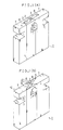
- Figs. 1(a) and 1(b) are perspective views showing an embodiment of a magnetic head obtained according to the present invention. These figures are enlarged in thickness and in portions around a gap portion 2.
- a soft magnetic alloy thin film 3 of FeAlSi has a thickness necessary for a track width in the gap portion 2, but is larger in thickness in other parts.
- the soft magnetic alloy thin film 3 is sandwiched between a nonmagnetic substrate 7 of crystalline glass and a low melting point glass equivalent in abrasion to the nonmagnetic substrate 7.
- the gap 2 is bonded by the low melting point glass 8. Coiling wire wound around the magnetic head 1 and a gap spacer are omitted in the drawings.
- a V-shaped groove 11 is formed in the surface of the substrate 7 of crystalline glass with a pitch A allowing for an eventual thickness of the magnetic head and a margin to cut off.
- An angle ⁇ between a side wall 9 of the V-shaped groove 11 where the soft magnetic alloy thin film 3 serving as a core is to be formed and a normal line in the initial surface of the substrate 7, and the pitch A are determined by the width of the core required for the intended magnetic head 1 and an azimuth.
- the FeAlSi alloy thin film 3 larger in thickness than that required for obtaining a track width of the magnetic head is formed on the side wall 9 of the V-shaped groove by spattering, electron-beam deposition or the like.
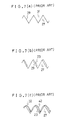
- the electron-beam deposition particles contributing to form a film have a uniform direction of an incidence (see Fig. 2(b)); if the direction of an incidence is adequately set, the shadowing effect of a top portion 12 of an adjacent V-shaped groove causes the thin film to be ended near the bottom of the side wall 9 of the V-shaped groove.
- the soft magnetic alloy thin film 3 generally has a multi-layer configuration including insulating layers of SiO2 or the like, allowing for a frequency region in which the magnetic head 1 works (The configuration is omitted in the drawings).
- the soft magnetic alloy thin film 3 of a gap portion (the top portion 12 of the V-shaped groove) is processed by ion milling to have a thickness required for a track width.
- the soft magnetic alloy thin film 3 is processed to be only in the gap portion 2 (the top portion 12 of the V-shaped groove) utilizing a self-shadowing effect of the top portion 12 of the V-shaped groove.
- a body 13 which includes the soft magnetic alloy thin film 3 only in the gap portion (the top portion 12 of the V-shaped groove) processed to have a thickness required for a track width.
- a similar ion milling processing is performed in the groove direction; however, if only a portion (front gap portion) of the intended magnetic head 1 facing to the surface at which the magnetic head 1 slides against a magnetic recording medium is processed by ion milling with a mask of a band structure, the soft magnetic alloy thin film 3 can be larger in thickness in the back gap portion. Thus, this is advantageous in an accuracy of alignment and reproducing efficiency.
- a V-shaped groove 11 is filled with low melting point glass 8 to obtain a core block 14 (see Fig. 2(f)).
- the core block 14 is cut at planes 15 orthogonal to both the bottom surface of the substrate and the longitudinal direction of the V-shaped groove into core pieces 16.
- the core block 14 is divided into four pieces to simplify the drawing, but it is practically divided into a larger number of pieces.
- the core pieces 16 thus obtained are subjected to a process similar to a processing of a well-known VCR ferrite head, i.e., a formation of a groove to be a window for coil winding, a precise polishing of a plane facing onto the gap and a formation of a gap spacer.
- the plane facing onto the gap is numbered by 17 in Fig. 2(g).
- the core pieces 16 are paired and fixed by putting pressure, being aligned with each other, where portions of the soft magnetic alloy thin film 3 exposed to the plane 17 facing onto the gap are opposed to each other; under such conditions, the temperature is raised to the point at which the low melting point glass 8 becomes adhesive to implement glass bonding.
- a magnetic head core block 18 is formed.
- the magnetic head core block 18 is composed of a number of magnetic head chips 19 connected together, and it is divided into the individual magnetic head chips 19 through a process mentioned below.
- the magnetic head core block 18 is divided at a hatched portion as a margin to cut off.
- the cross section is not in parallel with the soft magnetic alloy thin film 3 as is recognized in the drawing.
- the magnetic head chip 19 obtained as mentioned above is, similar to a prior art magnetic head, glued to a base plate and wound with coil and eventually subjected to a tape polishing to finish the magnetic head 1.
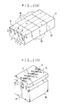
- Figs. 3(a) and 3(b) are perspective views showing other embodiments of the magnetic head obtained in the manufacturing method according to the present invention.
- a thickness and an area around a gap 2 are enlarged as in Fig. 1.
- Members corresponding to those in Fig. 1 are denoted by like reference numerals.
- a soft magnetic alloy thin film 3 of FeAlSi is formed only of a first soft magnetic alloy thin film 4 of a thickness required for a track width in a gap portion 2, while it is more thicker in other parts having a second soft magnetic alloy thin film 6 deposited on a thin film 5 of metal (e.g., Ti) serving as a mask against an ion milling.
- metal e.g., Ti
- a soft magnetic alloy thin film 3a (a multi-layer body of the first soft magnetic alloy thin film 4, the metal thin film 5 serving as a mask against the ion milling and the second soft magnetic alloy thin film 6 is referred to as "soft magnetic alloy thin film 3a" hereinafter) is placed between a nonmagnetic substrate 7 of crystalline glass and low melting point glass 8 equivalent in abrasion to the nonmagnetic substrate 7.
- the gap 2 is bonded by the low melting point glass 8. Coiling wire wound around the magnetic head 1a and a gap spacer are omitted in the drawings.
- a parallel V-shaped groove 11 is formed in the surface of a substrate 7 of crystalline glass with a pitch A allowing for an eventual thickness of the intended magnetic head and a margin to cut off.
- An angle ⁇ between a side wall 9 of the V-shaped groove 11 where the soft magnetic alloy thin film 3 serving as a core is to be formed and a normal line in the initial surface of the substrate 7, and the pitch A are determined by the width of the core required for the intended magnetic head 1 and an azimuth.
- a first FeAlSi ally thin film 4 required for obtaining a track width of the magnetic head, a metal thin film 5 (e.g., Ti) serving as a mask against the ion milling, and a second FeAlSi alloy thin film 6 are formed in this order in the side wall 9 of the V-shaped groove by spattering, electron-beam deposition or the like.
- a metal thin film 5 e.g., Ti
- a second FeAlSi alloy thin film 6 are formed in this order in the side wall 9 of the V-shaped groove by spattering, electron-beam deposition or the like.
- the first and second FeAlSi alloy thin films 4, 6 generally have a multi-layer configuration including insulating layers of SiO2 or the like, allowing for a frequency region in which the magnetic head 1 works (The configuration is omitted in the drawings).
- the metal thin film 5 serving as a mask against the ion milling should be 1 ⁇ m or under.
- the second soft magnetic alloy thin film 6 of a gap portion (the top portion 12 of the V-shaped groove) is processed by ion milling to have a thickness required for a track width.
- the metal thin film 5 serving as a mask against the ion milling is formed on the first soft magnetic alloy thin film 4, setting the condition of slight overmilling even if there is found slight unevenness in milling rate enables the second soft magnetic alloy thin film 6 alone to be removed without any unevenness; therefore, a uniform track width determined by a thickness of the first soft magnetic alloy thin film 4 can be obtained.
- a body 13 which has the second soft magnetic alloy thin film 6 only in the gap portion (the top portion 12 of the V-shaped groove) removed as shown in Fig. 4(e).
- a similar ion milling processing is performed in the groove direction; however, if only a portion (front gap portion) of the intended magnetic head 1 facing to the surface at which the magnetic head 1 slides against a magnetic recording mdeium is processed by ion milling with a mask of a band structure, the soft magnetic alloy thin film 3a can be larger in thickness in the back gap portion. Thus, this is advantageous in an accuracy of alignment and reproducing efficiency.
- a V-shaped groove 11 is filled with low melting point glass 8 to obtain a core block 14 (see Fig. 4(f)).
- the core block 14 is cut at planes 15 orthogonal to both the bottom surface of the substrate and the longitudinal direction of the V-shaped groove into core pieces 16.
- the core block 14 is divided into four pieces to simplify the drawing, but it is practically divided into a larger number of pieces.
- the core pieces 16 thus obtained are subjected to a process similar to a processing of a well-known VCR ferrite head, i.e., a formation of a groove to be a window for coil winding, a precise polishing of a plane facing onto the gap and a formation of a gap spacer.
- the plane facing onto the gap is numbered by 17 in Fig. 4(g).
- the core pieces 16 are paired and fixed by putting pressure, being aligned with each other, where portions of the first soft magnetic alloy thin film 4 exposed to the plane 17 facing onto the gap are opposed to each other; under such conditions, the temperature is raised to the point at which the low melting point glass 8 becomes adhesive to implement glass bonding.
- a magnetic head core block 18 is formed.
- the magnetic head core block 18 is composed of a number of magnetic head chips 19 connected together, and it is divided into the individual magnetic head chips 19 through a process mentioned below.
- the magnetic head core block 18 is divided at a hatched portion as a margin to cut off.
- the cross section is not in parallel with the soft magnetic alloy thin film 3a as is recognized in the drawing.
- the magnetic head chip 19 obtained as mentioned above is, similar to a prior art magnetic head, glued to a base plate and wound with coil and eventually subjected to a tape polishing to finish the magnetic head 1a.
- an ion milling is employed for processing a soft magnetic thin film at a top portion of groove walls to be a gap portion and a self shadowing effect of the top portion of the groove walls is utilized; hence, process steps such as a coating of resist, an exposure to light, a development and the like can be omitted, and a deterioration of processing accuracy caused in such steps can be avoided.
- a magnetic head with a small track width it can cope with a high-density recording and wide-band signal processing in a magnetic recording because its magnetic core is thoroughly formed of soft magnetic thin film and efficiency is secured.
Landscapes
- Engineering & Computer Science (AREA)
- Manufacturing & Machinery (AREA)
- Magnetic Heads (AREA)
Applications Claiming Priority (2)
| Application Number | Priority Date | Filing Date | Title |
|---|---|---|---|
| JP70962/90 | 1990-03-19 | ||
| JP2070962A JPH0785289B2 (ja) | 1990-03-19 | 1990-03-19 | 磁気ヘッドの製造方法 |
Publications (3)
| Publication Number | Publication Date |
|---|---|
| EP0448033A2 true EP0448033A2 (de) | 1991-09-25 |
| EP0448033A3 EP0448033A3 (en) | 1992-01-08 |
| EP0448033B1 EP0448033B1 (de) | 1994-06-01 |
Family
ID=13446653
Family Applications (1)
| Application Number | Title | Priority Date | Filing Date |
|---|---|---|---|
| EP91104227A Expired - Lifetime EP0448033B1 (de) | 1990-03-19 | 1991-03-19 | Verfahren zur Herstellung eines Magnetkopfes |
Country Status (4)
| Country | Link |
|---|---|
| US (1) | US5145555A (de) |
| EP (1) | EP0448033B1 (de) |
| JP (1) | JPH0785289B2 (de) |
| DE (1) | DE69102173T2 (de) |
Cited By (3)
| Publication number | Priority date | Publication date | Assignee | Title |
|---|---|---|---|---|
| EP0509461A3 (en) * | 1991-04-16 | 1993-04-07 | Sharp Kabushiki Kaisha | Magnetic head and method of manufacturing the same |
| EP0578234A3 (de) * | 1992-07-08 | 1994-02-16 | Sharp Kk | |
| CN1326791C (zh) * | 2005-05-26 | 2007-07-18 | 上海交通大学 | 在硼硅玻璃表面加工微槽阵列的方法 |
Families Citing this family (7)
| Publication number | Priority date | Publication date | Assignee | Title |
|---|---|---|---|---|
| CA2097388A1 (en) * | 1992-07-16 | 1994-01-17 | Susan Nord Bohlke | Topographical selective patterns |
| US6416880B1 (en) | 1993-12-09 | 2002-07-09 | Seagate Technology, Llc | Amorphous permalloy films and method of preparing the same |
| JP4539282B2 (ja) * | 2004-04-16 | 2010-09-08 | 富士電機デバイステクノロジー株式会社 | 垂直磁気記録媒体用ディスク基板及びそれを用いた垂直磁気記録媒体 |
| US20060210837A1 (en) * | 2004-04-16 | 2006-09-21 | Fuji Electric Device | Method of plating on a glass base plate, a method of manufacturing a disk substrate for a perpendicular magnetic recording medium, a disk substrate for a perpendicular magnetic recording medium, and a perpendicular magnetic recording medium |
| JP4475026B2 (ja) * | 2004-06-11 | 2010-06-09 | 富士電機デバイステクノロジー株式会社 | 無電解めっき方法、磁気記録媒体および磁気記録装置 |
| JP4479528B2 (ja) * | 2004-07-27 | 2010-06-09 | 富士電機デバイステクノロジー株式会社 | ガラス基体へのめっき方法、そのめっき方法を用いる磁気記録媒体用ディスク基板の製造方法及び垂直磁気記録媒体の製造方法 |
| JP4479571B2 (ja) * | 2005-04-08 | 2010-06-09 | 富士電機デバイステクノロジー株式会社 | 磁気記録媒体の製造方法 |
Family Cites Families (6)
| Publication number | Priority date | Publication date | Assignee | Title |
|---|---|---|---|---|
| JP2554041B2 (ja) * | 1984-09-27 | 1996-11-13 | シャープ株式会社 | 磁気ヘッドコアの製造方法 |
| JPS6413909A (en) * | 1987-07-07 | 1989-01-18 | Iseki Agricult Mach | Reaping part elevating apparatus using hydraulic transmission equipment |
| JPS6433709A (en) * | 1987-07-29 | 1989-02-03 | Sharp Kk | Magnetic head |
| JPH07306B2 (ja) * | 1988-06-30 | 1995-01-11 | フクビ化学工業株式会社 | 硬化型樹脂成形品の製造法 |
| JPH0235011A (ja) * | 1988-07-26 | 1990-02-05 | Kubota Ltd | 草刈機 |
| JP2829973B2 (ja) * | 1988-07-30 | 1998-12-02 | ソニー株式会社 | 磁気ヘッド |
-
1990
- 1990-03-19 JP JP2070962A patent/JPH0785289B2/ja not_active Expired - Fee Related
-
1991
- 1991-03-19 DE DE69102173T patent/DE69102173T2/de not_active Expired - Fee Related
- 1991-03-19 EP EP91104227A patent/EP0448033B1/de not_active Expired - Lifetime
- 1991-03-19 US US07/671,418 patent/US5145555A/en not_active Expired - Lifetime
Cited By (5)
| Publication number | Priority date | Publication date | Assignee | Title |
|---|---|---|---|---|
| EP0509461A3 (en) * | 1991-04-16 | 1993-04-07 | Sharp Kabushiki Kaisha | Magnetic head and method of manufacturing the same |
| US5276959A (en) * | 1991-04-16 | 1994-01-11 | Sharp Kabushiki Kaisha | Method of manufacturing a magnetic tape head |
| EP0578234A3 (de) * | 1992-07-08 | 1994-02-16 | Sharp Kk | |
| US5691866A (en) * | 1992-07-08 | 1997-11-25 | Sharp Kabushiki Kaisha | Magnetic head and method of manufacturing the same |
| CN1326791C (zh) * | 2005-05-26 | 2007-07-18 | 上海交通大学 | 在硼硅玻璃表面加工微槽阵列的方法 |
Also Published As
| Publication number | Publication date |
|---|---|
| EP0448033B1 (de) | 1994-06-01 |
| DE69102173D1 (de) | 1994-07-07 |
| DE69102173T2 (de) | 1995-01-12 |
| US5145555A (en) | 1992-09-08 |
| JPH03269809A (ja) | 1991-12-02 |
| EP0448033A3 (en) | 1992-01-08 |
| JPH0785289B2 (ja) | 1995-09-13 |
Similar Documents
| Publication | Publication Date | Title |
|---|---|---|
| EP0328104B1 (de) | Magnetischer Kopf und sein Herstellungsverfahren | |
| EP0661691B1 (de) | Magnetkopf | |
| US6278576B1 (en) | Magnetic head with magnetic metal film core having offset halves | |
| EP0448033B1 (de) | Verfahren zur Herstellung eines Magnetkopfes | |
| JP3394266B2 (ja) | 磁気書込/読取ヘッドの製造方法 | |
| US4769899A (en) | Method for making a twin head for electronic still camera and a method for making the same | |
| US4811142A (en) | Magnetic head for vertical magnetic recording and method of producing same | |
| US4476509A (en) | Thin film magnetic head and method of manufacturing the same | |
| US5276959A (en) | Method of manufacturing a magnetic tape head | |
| JP2895680B2 (ja) | 磁気ヘッドおよびその製造方法 | |
| EP0340781B1 (de) | Schwebender Magnetkopf und Herstellungsverfahren | |
| JP2669965B2 (ja) | 磁気ヘッドの製造方法 | |
| KR100229243B1 (ko) | 자기헤드 | |
| EP0379248A2 (de) | Herstellungsverfahren eines Magnetkopfes sowie nach dem Verfahren hergestellter Magnetkopf | |
| JP2977112B2 (ja) | 磁気ヘッドの製造方法 | |
| JP2891817B2 (ja) | 磁気ヘッド製造方法 | |
| JPS62262209A (ja) | 磁気ヘツド | |
| JP2572241B2 (ja) | 多チャンネル薄膜磁気ヘッド | |
| GB2129600A (en) | Methods of manufacturing magnetic thin film transducer heads | |
| JPS62202304A (ja) | 磁気ヘツドの製造方法 | |
| JPS62132206A (ja) | 磁気消去ヘツド | |
| JPH02130706A (ja) | 磁気ヘッド | |
| JPH0636221A (ja) | 磁気ヘッドとその製造方法 | |
| JPH07302408A (ja) | 磁気ヘッド及びその製造方法 | |
| JPH03252910A (ja) | 薄膜磁気ヘッド |
Legal Events
| Date | Code | Title | Description |
|---|---|---|---|
| PUAI | Public reference made under article 153(3) epc to a published international application that has entered the european phase |
Free format text: ORIGINAL CODE: 0009012 |
|
| 17P | Request for examination filed |
Effective date: 19910319 |
|
| AK | Designated contracting states |
Kind code of ref document: A2 Designated state(s): DE FR GB |
|
| PUAL | Search report despatched |
Free format text: ORIGINAL CODE: 0009013 |
|
| AK | Designated contracting states |
Kind code of ref document: A3 Designated state(s): DE FR GB |
|
| 17Q | First examination report despatched |
Effective date: 19930812 |
|
| GRAA | (expected) grant |
Free format text: ORIGINAL CODE: 0009210 |
|
| AK | Designated contracting states |
Kind code of ref document: B1 Designated state(s): DE FR GB |
|
| REF | Corresponds to: |
Ref document number: 69102173 Country of ref document: DE Date of ref document: 19940707 |
|
| ET | Fr: translation filed | ||
| PLBE | No opposition filed within time limit |
Free format text: ORIGINAL CODE: 0009261 |
|
| STAA | Information on the status of an ep patent application or granted ep patent |
Free format text: STATUS: NO OPPOSITION FILED WITHIN TIME LIMIT |
|
| 26N | No opposition filed | ||
| REG | Reference to a national code |
Ref country code: GB Ref legal event code: IF02 |
|
| PGFP | Annual fee paid to national office [announced via postgrant information from national office to epo] |
Ref country code: GB Payment date: 20070314 Year of fee payment: 17 |
|
| PGFP | Annual fee paid to national office [announced via postgrant information from national office to epo] |
Ref country code: DE Payment date: 20070315 Year of fee payment: 17 |
|
| PGFP | Annual fee paid to national office [announced via postgrant information from national office to epo] |
Ref country code: FR Payment date: 20070308 Year of fee payment: 17 |
|
| GBPC | Gb: european patent ceased through non-payment of renewal fee |
Effective date: 20080319 |
|
| REG | Reference to a national code |
Ref country code: FR Ref legal event code: ST Effective date: 20081125 |
|
| PG25 | Lapsed in a contracting state [announced via postgrant information from national office to epo] |
Ref country code: DE Free format text: LAPSE BECAUSE OF NON-PAYMENT OF DUE FEES Effective date: 20081001 |
|
| PG25 | Lapsed in a contracting state [announced via postgrant information from national office to epo] |
Ref country code: FR Free format text: LAPSE BECAUSE OF NON-PAYMENT OF DUE FEES Effective date: 20080331 |
|
| PG25 | Lapsed in a contracting state [announced via postgrant information from national office to epo] |
Ref country code: GB Free format text: LAPSE BECAUSE OF NON-PAYMENT OF DUE FEES Effective date: 20080319 |