EP0452501A1 - Elektro-abrasives Polierverfahren zur Erzielung besonders glatter Spiegelflächen auf den Innenwänden von Rohren - Google Patents
Elektro-abrasives Polierverfahren zur Erzielung besonders glatter Spiegelflächen auf den Innenwänden von Rohren Download PDFInfo
- Publication number
- EP0452501A1 EP0452501A1 EP90915818A EP90915818A EP0452501A1 EP 0452501 A1 EP0452501 A1 EP 0452501A1 EP 90915818 A EP90915818 A EP 90915818A EP 90915818 A EP90915818 A EP 90915818A EP 0452501 A1 EP0452501 A1 EP 0452501A1
- Authority
- EP
- European Patent Office
- Prior art keywords
- small
- diameter pipe
- tool
- finishing
- mirror
- Prior art date
- Legal status (The legal status is an assumption and is not a legal conclusion. Google has not performed a legal analysis and makes no representation as to the accuracy of the status listed.)
- Granted
Links
- 238000007517 polishing process Methods 0.000 title claims description 29
- 239000004677 Nylon Substances 0.000 claims abstract description 25
- 229920001778 nylon Polymers 0.000 claims abstract description 25
- JOYRKODLDBILNP-UHFFFAOYSA-N Ethyl urethane Chemical compound CCOC(N)=O JOYRKODLDBILNP-UHFFFAOYSA-N 0.000 claims abstract description 16
- 238000007730 finishing process Methods 0.000 claims abstract description 14
- 230000009471 action Effects 0.000 claims abstract description 11
- 238000005498 polishing Methods 0.000 claims description 53
- 239000006061 abrasive grain Substances 0.000 claims description 37
- 239000003792 electrolyte Substances 0.000 claims description 33
- 238000000034 method Methods 0.000 abstract description 23
- 230000003746 surface roughness Effects 0.000 abstract description 17
- 230000008569 process Effects 0.000 abstract description 11
- 239000000463 material Substances 0.000 abstract description 7
- 239000008151 electrolyte solution Substances 0.000 abstract 1
- 239000004744 fabric Substances 0.000 abstract 1
- 238000010002 mechanical finishing Methods 0.000 abstract 1
- 239000010935 stainless steel Substances 0.000 description 10
- 229910001220 stainless steel Inorganic materials 0.000 description 10
- 239000013013 elastic material Substances 0.000 description 7
- 238000000354 decomposition reaction Methods 0.000 description 6
- VWDWKYIASSYTQR-UHFFFAOYSA-N sodium nitrate Chemical compound [Na+].[O-][N+]([O-])=O VWDWKYIASSYTQR-UHFFFAOYSA-N 0.000 description 6
- 230000007246 mechanism Effects 0.000 description 5
- 229910052751 metal Inorganic materials 0.000 description 5
- 239000002184 metal Substances 0.000 description 5
- 239000012530 fluid Substances 0.000 description 3
- 235000010344 sodium nitrate Nutrition 0.000 description 3
- 239000007864 aqueous solution Substances 0.000 description 2
- 238000009826 distribution Methods 0.000 description 2
- 238000010828 elution Methods 0.000 description 2
- 239000007789 gas Substances 0.000 description 2
- 230000002093 peripheral effect Effects 0.000 description 2
- 238000002791 soaking Methods 0.000 description 2
- 239000004317 sodium nitrate Substances 0.000 description 2
- RYGMFSIKBFXOCR-UHFFFAOYSA-N Copper Chemical compound [Cu] RYGMFSIKBFXOCR-UHFFFAOYSA-N 0.000 description 1
- 229910001021 Ferroalloy Inorganic materials 0.000 description 1
- RTAQQCXQSZGOHL-UHFFFAOYSA-N Titanium Chemical compound [Ti] RTAQQCXQSZGOHL-UHFFFAOYSA-N 0.000 description 1
- 239000000853 adhesive Substances 0.000 description 1
- 230000001070 adhesive effect Effects 0.000 description 1
- 230000002411 adverse Effects 0.000 description 1
- 230000032683 aging Effects 0.000 description 1
- 229910052782 aluminium Inorganic materials 0.000 description 1
- XAGFODPZIPBFFR-UHFFFAOYSA-N aluminium Chemical compound [Al] XAGFODPZIPBFFR-UHFFFAOYSA-N 0.000 description 1
- PNEYBMLMFCGWSK-UHFFFAOYSA-N aluminium oxide Inorganic materials [O-2].[O-2].[O-2].[Al+3].[Al+3] PNEYBMLMFCGWSK-UHFFFAOYSA-N 0.000 description 1
- 239000010953 base metal Substances 0.000 description 1
- 230000008901 benefit Effects 0.000 description 1
- 230000015572 biosynthetic process Effects 0.000 description 1
- 230000008859 change Effects 0.000 description 1
- 239000002131 composite material Substances 0.000 description 1
- 239000004020 conductor Substances 0.000 description 1
- 239000010949 copper Substances 0.000 description 1
- 229910052802 copper Inorganic materials 0.000 description 1
- 238000005520 cutting process Methods 0.000 description 1
- 230000007547 defect Effects 0.000 description 1
- 230000000994 depressogenic effect Effects 0.000 description 1
- 230000002542 deteriorative effect Effects 0.000 description 1
- 238000005553 drilling Methods 0.000 description 1
- 230000000694 effects Effects 0.000 description 1
- 230000002349 favourable effect Effects 0.000 description 1
- 230000005484 gravity Effects 0.000 description 1
- 238000003754 machining Methods 0.000 description 1
- 238000004519 manufacturing process Methods 0.000 description 1
- 150000002739 metals Chemical class 0.000 description 1
- 239000005011 phenolic resin Substances 0.000 description 1
- 239000004033 plastic Substances 0.000 description 1
- 238000001556 precipitation Methods 0.000 description 1
- 230000009467 reduction Effects 0.000 description 1
- 239000004065 semiconductor Substances 0.000 description 1
- 125000006850 spacer group Chemical group 0.000 description 1
- 239000000126 substance Substances 0.000 description 1
- 239000010936 titanium Substances 0.000 description 1
- 229910052719 titanium Inorganic materials 0.000 description 1
Images




Classifications
-
- B—PERFORMING OPERATIONS; TRANSPORTING
- B23—MACHINE TOOLS; METAL-WORKING NOT OTHERWISE PROVIDED FOR
- B23H—WORKING OF METAL BY THE ACTION OF A HIGH CONCENTRATION OF ELECTRIC CURRENT ON A WORKPIECE USING AN ELECTRODE WHICH TAKES THE PLACE OF A TOOL; SUCH WORKING COMBINED WITH OTHER FORMS OF WORKING OF METAL
- B23H9/00—Machining specially adapted for treating particular metal objects or for obtaining special effects or results on metal objects
- B23H9/005—Machining elongated bodies, e.g. rods
-
- B—PERFORMING OPERATIONS; TRANSPORTING
- B23—MACHINE TOOLS; METAL-WORKING NOT OTHERWISE PROVIDED FOR
- B23H—WORKING OF METAL BY THE ACTION OF A HIGH CONCENTRATION OF ELECTRIC CURRENT ON A WORKPIECE USING AN ELECTRODE WHICH TAKES THE PLACE OF A TOOL; SUCH WORKING COMBINED WITH OTHER FORMS OF WORKING OF METAL
- B23H5/00—Combined machining
- B23H5/06—Electrochemical machining combined with mechanical working, e.g. grinding or honing
- B23H5/08—Electrolytic grinding
Definitions
- This inveniton relates to the electro-abrasive polishing process of the inner surface of pipes to such an extra-smooth mirror finish as is suited for the above described applicaiton.
- This method uses a tool consisting of a rotating shaft of conductive material that is wrapped with a non-woven nylon sheet or other liquid-permeable elastic material which softly supports abrasive grains there-around.
- the tool is inserted in a cylinderical workpiece whose inner surface is electrolytically decomposed by a small amount of current passed through the electrolyte between the workpiece and the tool.
- the tool and workpiece are moved relative to each other, whereby the abrasive grains supported by the elastic material mechanically polish the inner surface of the workpiece.
- the elastic material deforms in accordance with the internal contour of the cylinder, the abrasive grains are pressed against the inner surface without applying excessive pressure. Therefore, the inner surface of the cylinder is polished without deteriorating the accuracy of its profile, with the surface roughness reduced to be low 0.2 ⁇ m Rmax usually and to approximately 0.1 ⁇ m under the most favorable conditions.
- An object of this inveniton is to provide an electro-abrasive polishing process of the inner surface of a pipe whose original roughness is approximately 3 ⁇ m Rmax to an extra-smooth mirror finish of the order of tens of nm.
- Another object of this invention is to provide a method of achieving the above extra-smooth mirror finish with the use of a simple tool and equipment.
- Yet another object of this invention is to provide a method of achieving the above extra-smooth mirror finish in an extremely short time by applying a quick pre-polishing and a subsequent mirror polishing process.
- an electro-abrasive polishing process of the inner surface of pipes to an extra-smooth mirror finish according to this invention comprises two processes.
- One is a preliminary-polishing process in which a tool electrode, which comprises a core electrode shaft and a non-woven nylon sheet to support abrasive grains and to wrap around the core electrode, is inserted in a small-diameter pipe that is to be worked, the small-diameter pipe serving as the anode and the tool electrode as the cathode.
- a tool electrode which comprises a core electrode shaft and a non-woven nylon sheet to support abrasive grains and to wrap around the core electrode
- the small-diameter pipe serving as the anode and the tool electrode as the cathode.
- the other is a subsequent mirror-finishing process which is carried out by use of a mirror-finishing tool electrode that comprises a core electrode wrapped with a sheet of urethane.
- the tool electrode which serves as the cathode, is inserted in the small-diameter pipe that serves as the anode.
- the inner surface of the pipe is polished by the action of electrolytic decomposition.
- the tool electrode is rotated and it or the pipe is axially moved back and forth relative to each other to achieve, in support of the action of the free fine abrasive grains in the electrolyte, the mechanical mirror polishing of the inner surface of the pipe.
- the preliminary-polishing process may be achieved in several stages using several tools wrapped with non-woven nylon sheets comprising increasingly fine abrasive grains. Also, addition of free fine abrasive grains to the electrolyte is necessary to obtain the effect of the mechanical polish in the mirror-finishing process.
- the preliminary-polishing tool wrapped with a non-woven nylon sheet comprising abrasive grains performs electrolytic decomposition and the rotation of the tool and axial reciprocation of it or the small-diameter pipe relative to each other provide mechnical polishing in the preliminary-polishing process.
- the mirro-finishing tool wrapped with an urethane sheet performs electrolytic decomposition and the rotation of the tool and axial reciprocation of it or the small-diamter pipe relative to each other in the electrolyte mixed with free fine abrasive grains provide mechanical polishing.
- these actions, in combination are so effective that the original surface roughness of approximately 3 ⁇ m Rmax is reduced to an extra-smooth mirror finish of the order of tens of nanometer.
- Figs. 1-A and -B are perspective views showing a preliminary-polishing tool electrode used in the preliminary-polishing process, in fabrication and on completion.
- Fig. 1-C is a similar perspective view showing a finishing tool used in the subsequent mirror-finishing process.
- Fig. 2 graphically shows the relationship between the peripheral speed and mean angle of intersection of the abrasive grains.
- Fig. 3 is a schematic cross-sectional view showing an apparatus used in implementing the method of this inveniton.
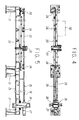
- Figs. 4 and 5 are plan and front views showing another apparatus.
- Fig. 6 graphically shows the distribution of roughness of the inner surface of an unprocessed pipe.
- Fi. 7 shows how the original surface roughness is improved by a non-woven nylon sheet comprising abrasive grains of #500.
- Figs 8-A and 8B graphically show the surface roughness improvements achieved in a rough and an intermediate-polishing tests.
- Fig. 9 graphically shows how the surface roughness changes with time when mirror-polishing is applied with a finishing tool electrode wrapped with an urethane sheet.
- Pipes whose inner surface is polished by the method of this invention are generally stainless steel pipes of relatively small diameter falling below the diameter limit of approximately 150 mm. If necessary, preliminary machining is applied to the inner surface to obtain the desired interior roundness.
- This invention of an extra-smooth mirror-finishing method comprises a preliminary-polishing process and a subsequent mirror-finishing process.
- a preliminary-polishing tool electrode 1 used in the preliminary-polishing process comprises, as shown in Fig. 1-A, a core electrode 2 of stainless steel pipe or other similar material wrapped with a tape of elastic material 3, such as porous urethane, that readily passes the electrolyte. Then, a tape of non-woven nylon sheet comprising abrasive grains 4 is helically wrapped there-around, with both ends thereof affixed with adhesive as shown in Fig.1-B.
- the urethane sheet may be replaced with other equivalent elastic materials that pass the electrolyte with equivalent ease.
- the non-woven nylon ssheet 4 comprising abrasive grains may be wrapped directly around the core electrode of an appropriate outer diamter machined accurately. Then, the non-woven nylon sheet 4 must have such elasticity as will provide the desired working pressure.
- the elasticity of the non-woven nylon sheet 4 changes somewhat with the lapse of time.
- the elastic material 3 should have a modulus of elasticity of less than 100 kPa, or preferably approximately 50 kPa, and an ability to pass a few liters of the electrolyte per minute when the tool electrode has a diameter of about 100 mm.
- a mirror-finishing tool electrode shown in Fig. 1-C by contrast, comprises a similar core electrode 6 wrapped with a sheet of urethane 7 alone.
- the sheet of urethane 7 may be the same as that used with the tool electrode 1 for preliminary polishing.
- the entirety of the surface being worked is always in contact with the tool, so that the pressure with which the tool is pressed against the surface depends almost solely on the diameter of the tool. Accordingly, the diameter of the preliminary-polishing tool 1 and the mirror-finishing tool 5 must be determined with the working pressure taken into account.
- the working pressure which depends on the area of contact between the inner surface of the pipe and the tool inserted therein, is usually set so that the working pressure is kept within an appropriate range, preferably between approximately 5 and 100 kPa. But the working pressure should by no means be limited to the above range.
- the tool electrode In polishing, the tool electrode is rotated and it or the pipe is axially reciprocated relative to each other.
- the reciprocation provides such a large angle of intersection to the traces of the abrasive grains that prevents the generation of deep circular steaks, significantly increases surface smoothness, and averages the longitudinal unevenness in surface finish that results from the uneveness in the surface condition of the polishing tool.
- the tool or small-diameter pipe should be preferably be axailly reciprocated relative to each other at such a speed as will provide a mean angle of intersection of at least 2 degrees to the traces of the abrasive grains on the inner surface of the pipe.
- the mean angle of intersection must be approximately between 5 and 6 degrees.
- the mean angle of intersection is set within the limits where no such problems arise.
- Fig. 2 shows the relationship between the peripheral speed of the tool electrode and the mean angle of intersection at different mean speeds of reciprocation.
- Electrolytic metal removal process is performed by passing a small amount of current through the electrolyte between the small-diameter pipe that serves as the anotde and the preliminary-polishing tool electrode 1 or mirror-finishing tool electrode 5 that serves as the cathode. At the same time, as mentioned previously, the tool electrode is rotated and it or the pipe is axially reciprocated relative to each other.
- free fine abrasive grains may be added to the electrolyte to achieve more effective mechanical mirror polishing by taking advantage of their abrasive action.
- the size of the free abrasive grains should preferably be approximately #10000.
- the concentration of the abrasive grains needs not be higher than 1 percent. If the precipitation in the electrolyte circulation system is negligible, 0.5 percent is enough.
- the deviation of the core electrode from the central axis of the small-diameter pipe and the pressure with which the tool electrode is pressed against the inner surface of the pipe have a great influence on the critical current density.
- the local variation in inter-electrode resistance that arises when the tape comprising abrasive grains is wound nonuniformly also has an influence. If these shortcomings are improved, it becomes possible to increase the polishing current density to approximately 0.5 A/cm2 and thereby increase the polishing speed in the preliminary polishing process.
- the application of pulsed current permits dispensing with the downtime needed for the re-soaking of the electrolyte and also increasing the critical current density.
- the time-averaged current density in the raised portions of the surface is kept at as high a percentage as of the order of tens. Meanwhile, the current density in the depressed portions of the surface is kept very low. As a consequence, the actions of the abrasive grains and the electrolytic elution produce such a multiplied result that the surface is rapidly made smooth without necessitating great material removal.
- Fig. 3 shows an apparatus suited for polishing the inner suface of shorter small-diameter pipes.
- Reference numeral 10 designates a small-diameter pipe whose inner surface is to be polished.
- a holder 11 keeps the pipe 10 in a vertical position, with a plastic guide 12 holding one end of the pipe 10 in contact with the bottom of an electrolyte resservoir 13.
- a tool electrode 14 is of the type illustrated in Figs. 1-A and 1-B.
- a core electrode 15 is adapted to be connected to a rotating and axially reciprocating device not shown.
- the tool electrode 14 and the small-diameter pipe 10 are respectively connected to the cathode and the anode of a power supply unit not shown so that a current for electrolytic decomposition is passed between the tool electrode 14 and the pipe 10.
- An apparatus shown in Figs. 4 and 5 is suited for polishing the inner surface of small-diameter pipes of such greater length as, for example, 4 m.
- On beds 22, 23 supported on legs 21 are mounted supports 24 that support portions of a small-diameter pipe 20 held in a horizontal position and a tool stand 26 that aligns and connects a tool electrode 25 to the small-diameter pipe 20.
- the tool stand 26 is slidable in the direction of the axis of the small-diameter pipe 20 over the bed 23.
- the tool stand 26 is equipped with a motor 27 that rotates the tool electrode 25 and a motor 28 that moves the tool stand 26 itself along the axis of the small-diameter pipe.
- a reciprocating device 30 that moves back and forth the small-diameter pipe 20 along the axis thereof is mounted on the bed 22.
- the reciprocating device 30 may be a device that holds and moves the small-diameter pipe 20 in the direction of the axis thereof, or a pair of rotating rollers that hold the small-diameter pipe 20 therebetween and moves it by the rotation of the rollers, or other some other appropriate devices.
- a mechanism to slowly rotate the small-diameter pipe may be attached to the reciprocating device so that the pipe rotatably placed on the supports 24 is rotated while being polished.
- Reference numeral 31 denotes a mechanism that holds the small-diameter pipe 20 in position. It is also possible to provide a device to slowly rotate the small-diameter pipe 20 to the holding mechanism 31.
- This apparatus has a long rod 32 that serves as the core electrode of the tool electrode 25.
- the motor 27 rotates the rod 32 so that the small-diameter pipe 20 is axially fed at a constant speed, whereas the reciprocating device 30 moves the small-diameter pipe 20 back and forth along the axis thereof.
- the tool stand 26 may be designed to perform two functions of constant-speed feed and reciprocation. Basically it is preferable to pass the tool electrode 25 through the small-diameter pipe 20 from one end to the other end thereof to complete polishing in a single pass. But provision may be also made to reciprocate the tool electrode 25 as required.
- the tool electrode 25 may be of a composite type that is wrapped with tapes of rough- and medium-textured non-woven nylon sheets and of urethane sheet for mirror finishing in that order from the leading end thereof. Or otherwise, the same small-diameter pipe may be polished in steps on different polishing apparatuses employing different tool electrodes individually wrapped with such different tapes.
- the tool electrod 25 and the small-diameter pipe 20 are respectively connected to the cathode and anode of a power supply unit not shown.
- the electrolyte is supplied under pressure either from one end of the small-diameter pipe 20 or through the core electrode of the tool electrode 25.
- a rough, an intermediate-polishing and a mirror-finishing tool electrode of the types shown in Figs. 1-A, 1-B and 1-C were used.
- Bright annealed stainless steel pipe having an outer diameter of 6.35 mm, a wall thickness of 1mm and a length of 35 mm(of JIS SUS 316L type, with an inner surface area of approximately 4.8 cm2) was used.
- Rough and intermediate polishing were performed with tool electrodes each of which consisted of a stainless steel pipe having an outer diameter of 2 mm and helically wrapped with tapes of urethane and non-woven nylon sheet comprising abrasive grains, with both ends thereof bonded firmly, until the outer diameter became approximately 5 mm.
- the tool electrode for mirror-finishing consisted of a similar stainless steel pipe wrapped with urethane alone.
- Polishing was carried out using the above tools that were attached to the spindle of a polishing machine remodeled from a drilling machine as shown in Fig. 3.
- the work-piece was rotated 23 times per second and reciprocated with a frequency of 7 Hz over a distance of 8 mm.
- the circle in Fig. 2 indicates the resulting mean angle of intersection.
- the polishing spacers was descended at intervals of 30 seconds to separate the tool away from the small-diameter pipe for a short period of time (approximately 12 seconds) to allow the re-soaking of the electrolyte.
- a 20 percent aqueous solution of sodium nitrate (NaNo3) was used as the electolyte.
- Fig. 6 shows the distribution of surface roughess Rmax (cut off at 0.8 mm) derived from a roughness profile curve (which was drawn on the basis of as many data as 630).
- the surface roughness was measured with Talysurf Type 5 made by Rand Taylor Hobson. When the presence of surface defects is neglected, it is therefore enough to remove the material by approximately 3 ⁇ m with the non-woven nylon sheet comprising abrasive grains of #500 in the first rough polishing process.
- Fig. 7 shows how far the original surface roughness is improved by the rough-polishing with the non-woven nylon sheet comprising abrasive grains of #500 , the surface roughness was reduced to a minimum level in about 10 minutes.
- Figs. 8-A and 8-B show the surface roughness improvements (cut off at 0.25 mm) achieved in the rough and intermediate polishing processes that were carried out for a period of 2 minutes each, with a current density of 0.3 A/cm2.
- the surface roughly polished with the non-woven nylon sheet comprising abrasive grains of #500 served as the original surface for the intermediate polishing with the non-woven nylon sheet comprising abrasive grains of #3000.
- Fig. 9 shows how the surface roughness profile curve changes with time in the mirror-finishing process in which the urethane-wrapped tool electrode is used (magnification: 20,000 times longitudinally and 100 times transversely).
- the size of the abrasive alumina grains added to the electrolyte (a 20 percent aqueous solution of sodium nitrate (NaNO3)) averaged a little under 1 ⁇ m.
- the electrolytic extra-smooth mirror polishing method of this invention By applying the electrolytic extra-smooth mirror polishing method of this invention to the inner surface of a bright annealed stainless steel pipe having an inner diameter of 4.35 mm, the original surface roughness of approximately 3 ⁇ m Rmax was reduced to an extra-smooth mirror finish of approximately 0.05 ⁇ m. Two minutes each were consumed for the rough and intermediate polishing with the non-woven nylon sheets comprising abrasive grains of #500 and #3000 and the mirror-finishing process with the urethane sheet. As there is practically no flow of the electrolyte, operation of each process must be stopped three times for some 30 seconds in total to permit the re-soakin of the electrolyte. This results in the total polishing time of a little less than 8 minutes, which is economically acceptable when the ease with which more efficient multi-spindle operation can be introduced is taken into consideration.
- the method of this invention provides an extra-smooth mirror finish to the inner surface of stainless steel pipes that is needed in chemical, food processing, nuclear, biological and many other sectors of industry.
- the method is applicable to the polishing of the inner surface of pipes of not only stainless steel but also aluminum, titanium, copper, ferro-alloys and many other metals.
Landscapes
- Engineering & Computer Science (AREA)
- Mechanical Engineering (AREA)
- Chemical & Material Sciences (AREA)
- Chemical Kinetics & Catalysis (AREA)
- Electrochemistry (AREA)
- Physics & Mathematics (AREA)
- Thermal Sciences (AREA)
- Electrical Discharge Machining, Electrochemical Machining, And Combined Machining (AREA)
- Finish Polishing, Edge Sharpening, And Grinding By Specific Grinding Devices (AREA)
Applications Claiming Priority (3)
| Application Number | Priority Date | Filing Date | Title |
|---|---|---|---|
| JP285259/89 | 1989-11-01 | ||
| JP1285259A JPH0794090B2 (ja) | 1989-11-01 | 1989-11-01 | 小径管内面の電解砥粒超鏡面仕上げ方法 |
| PCT/JP1990/001389 WO1991006388A1 (en) | 1989-11-01 | 1990-10-30 | Method of super-mirror finishing with electrolytic grinding for internal surface of small-diameter tube |
Publications (3)
| Publication Number | Publication Date |
|---|---|
| EP0452501A1 true EP0452501A1 (de) | 1991-10-23 |
| EP0452501A4 EP0452501A4 (en) | 1992-08-12 |
| EP0452501B1 EP0452501B1 (de) | 1995-09-20 |
Family
ID=17689184
Family Applications (1)
| Application Number | Title | Priority Date | Filing Date |
|---|---|---|---|
| EP90915818A Expired - Lifetime EP0452501B1 (de) | 1989-11-01 | 1990-10-30 | Elektro-abrasives Polierverfahren zur Erzielung besonders glatter Spiegelflächen auf den Innenwänden von Rohren |
Country Status (7)
| Country | Link |
|---|---|
| US (1) | US5294309A (de) |
| EP (1) | EP0452501B1 (de) |
| JP (1) | JPH0794090B2 (de) |
| CA (1) | CA2044581C (de) |
| DE (1) | DE69022579T2 (de) |
| ES (1) | ES2078355T3 (de) |
| WO (1) | WO1991006388A1 (de) |
Cited By (8)
| Publication number | Priority date | Publication date | Assignee | Title |
|---|---|---|---|---|
| EP1000694A3 (de) * | 1998-11-09 | 2001-08-16 | Nissin Unyu Kogyo Co., Ltd. | Verfahren zur elektrolytischen Polieren von Werkstücke mit Anwendung specieller Schleifmaterialien |
| EP0951960A4 (de) * | 1997-11-10 | 2002-10-30 | Nissin Unyu Kogyo Co Ltd | Verfahren und vorrichtung zum polieren des inneren oberfläche eine zylindrischenteilen einen länglichen erzeugnisses und länglichen zylindrischen erzeugnis |
| RU2195390C2 (ru) * | 2000-05-25 | 2002-12-27 | Воронежский государственный технический университет | Способ электрохимикомеханической обработки каналов и устройство для его осуществления |
| EP1308221A3 (de) * | 2001-10-31 | 2003-12-17 | Terumo Kabushiki Kaisha | Metallrohr und Verfahren zu seiner Herstellung |
| EP1323483A3 (de) * | 2001-12-27 | 2003-12-17 | Terumo Kabushiki Kaisha | Metallrohr und Verfahren zu seiner Herstellung |
| WO2005042993A1 (en) * | 2003-10-02 | 2005-05-12 | Minebea Co. Ltd. | Self-lubricating bearings |
| CN112813244A (zh) * | 2020-12-30 | 2021-05-18 | 上海久砾不锈钢管有限公司 | 一种不锈钢管的表面处理方法及其应用 |
| CN119566428A (zh) * | 2024-12-11 | 2025-03-07 | 南京航空航天大学 | 柔性编织电极及电化学抛光复杂内通道方法 |
Families Citing this family (24)
| Publication number | Priority date | Publication date | Assignee | Title |
|---|---|---|---|---|
| US5491030A (en) * | 1992-06-26 | 1996-02-13 | Asahi Tec Corporation | Surface finishing for metal moldings |
| JP2569425B2 (ja) * | 1994-03-04 | 1997-01-08 | 工業技術院長 | ステンレス鋼の電解砥粒研磨方法 |
| JPH07266837A (ja) * | 1994-03-29 | 1995-10-17 | Horikiri Bane Seisakusho:Kk | 中空スタビライザの製造法 |
| JP3853428B2 (ja) * | 1995-08-25 | 2006-12-06 | Jfeスチール株式会社 | 鋼管の絞り圧延方法および設備 |
| KR100236918B1 (ko) * | 1997-09-23 | 2000-01-15 | 윤덕용 | 자기전해연마장치 |
| DE19924762C1 (de) * | 1999-05-29 | 2001-01-11 | Butting H Gmbh & Co Kg | Verfahren und Vorrichtung zur Innenoberflächenbehandlung von metallischen Rohren |
| US20040194930A1 (en) * | 1999-06-22 | 2004-10-07 | Societe Meusienne De Constructions Mecaniques | Tube for use in fluid evaporation techniques, in particular food fluid |
| EP1295647A1 (de) * | 2001-09-24 | 2003-03-26 | The Technology Partnership Public Limited Company | Düsen in perforierten Membranen und ihre Herstellung |
| JP2004299030A (ja) * | 2003-04-01 | 2004-10-28 | Misuzu Kogyo:Kk | 電解砥粒研磨用研磨工具 |
| AT500259B1 (de) * | 2003-09-09 | 2007-08-15 | Austria Tech & System Tech | Dünnschichtanordnung und verfahren zum herstellen einer solchen dünnschichtanordnung |
| DE102004040217A1 (de) * | 2004-08-19 | 2006-03-02 | Mtu Aero Engines Gmbh | Elektrode zum elektrochemischen Senken |
| US7396448B2 (en) * | 2004-09-29 | 2008-07-08 | Think Laboratory Co., Ltd. | Method for roll to be processed before forming cell and method for grinding roll |
| CA2802171C (en) | 2010-06-28 | 2015-11-24 | Nippon Steel & Sumitomo Metal Corporation | Heat transfer tube for steam generator and method for producing the same |
| JP2014085254A (ja) * | 2012-10-24 | 2014-05-12 | Asahi Organic Chemicals Industry Co Ltd | 超音波流量計及びこれを備える流体制御装置 |
| US9782829B2 (en) * | 2013-11-26 | 2017-10-10 | Honeywell International Inc. | Methods and systems for manufacturing components from articles formed by additive-manufacturing processes |
| CN104759717B (zh) * | 2015-04-07 | 2018-12-28 | 海安欣凯富机械科技有限公司 | 基于双峰脉冲电流电化学复合机械的金属回转面的光整加工方法 |
| MY190147A (en) * | 2015-07-01 | 2022-03-30 | Shell Int Research | A method of expanding a tubular and expandable tubular |
| JP7149083B2 (ja) * | 2018-03-09 | 2022-10-06 | 日立造船株式会社 | 電解加工器具および電解加工方法 |
| CN111014857A (zh) * | 2019-12-27 | 2020-04-17 | 常州工学院 | 一种循环式电解磨削线切割加工装置及方法 |
| CN111014856A (zh) * | 2019-12-27 | 2020-04-17 | 常州工学院 | 一种往复式电解磨削线切割加工装置及方法 |
| CN112658415B (zh) * | 2020-12-10 | 2022-06-28 | 南京航空航天大学 | 用于光整内部结构的抽吸式电解加工装置及方法 |
| CN114921842B (zh) * | 2022-03-24 | 2023-09-29 | 南京航空航天大学 | 一种等离子电解抛光大型回转零件内壁的装置及方法 |
| CN116121842A (zh) * | 2022-12-28 | 2023-05-16 | 浙江久立特材科技股份有限公司 | 一种小口径管道内表面电化学抛光装置 |
| CN119238252B (zh) * | 2024-09-10 | 2025-09-26 | 东风汽车集团股份有限公司 | 一种往复式消除齿轮振纹的抛光装置 |
Family Cites Families (12)
| Publication number | Priority date | Publication date | Assignee | Title |
|---|---|---|---|---|
| JPS5448398A (en) * | 1977-09-24 | 1979-04-16 | Hitachi Zosen Corp | Combinated grinding method and its device for metal pipe inside |
| US4294673A (en) * | 1979-02-24 | 1981-10-13 | Hitachi Shipbuilding & Engineering Co., Ltd. | Method of mirror-finishing a cylindrical workpiece |
| JPS58137525A (ja) * | 1982-02-09 | 1983-08-16 | Yasuo Kimoto | 超精密電解複合砥粒加工法 |
| JPS59227324A (ja) * | 1983-06-06 | 1984-12-20 | Hitachi Zosen Corp | 穴内面の仕上げ方法 |
| JPS6034227A (ja) * | 1983-08-03 | 1985-02-21 | Agency Of Ind Science & Technol | 円筒内面の電解砥粒研磨法 |
| JPS6071122A (ja) * | 1983-09-28 | 1985-04-23 | Hitachi Zosen Corp | 電解複合鏡面加工方法 |
| DE3343396A1 (de) * | 1983-11-30 | 1985-06-05 | Kraftwerk Union AG, 4330 Mülheim | Verfahren zum dekontaminieren metallischer komponenten einer kerntechnischen anlage |
| DE3345278A1 (de) * | 1983-12-14 | 1985-06-27 | Kraftwerk Union AG, 4330 Mülheim | Vorrichtung zum elektropolieren der innenoberflaeche von hohlzylindrischen koerpern |
| JPS62157722A (ja) * | 1985-12-30 | 1987-07-13 | Nissho Asutetsuku Kk | 金属管の内面研磨方法 |
| JPS62246419A (ja) * | 1986-04-17 | 1987-10-27 | Kobe Steel Ltd | ジルコニウムまたはジルコニウム合金の電解研削方法 |
| EP0247209B1 (de) * | 1986-05-20 | 1990-07-18 | Poligrat Gmbh | Vorrichtung und Verfahren zum elektrochemischen Polieren der Innenflächen von Rohren |
| JP2693432B2 (ja) * | 1987-03-26 | 1997-12-24 | 工業技術院長 | チタン材の鏡面研磨法 |
-
1989
- 1989-11-01 JP JP1285259A patent/JPH0794090B2/ja not_active Expired - Fee Related
-
1990
- 1990-10-30 EP EP90915818A patent/EP0452501B1/de not_active Expired - Lifetime
- 1990-10-30 WO PCT/JP1990/001389 patent/WO1991006388A1/ja not_active Ceased
- 1990-10-30 US US07/691,012 patent/US5294309A/en not_active Expired - Lifetime
- 1990-10-30 ES ES90915818T patent/ES2078355T3/es not_active Expired - Lifetime
- 1990-10-30 CA CA002044581A patent/CA2044581C/en not_active Expired - Fee Related
- 1990-10-30 DE DE69022579T patent/DE69022579T2/de not_active Expired - Fee Related
Cited By (15)
| Publication number | Priority date | Publication date | Assignee | Title |
|---|---|---|---|---|
| EP0951960A4 (de) * | 1997-11-10 | 2002-10-30 | Nissin Unyu Kogyo Co Ltd | Verfahren und vorrichtung zum polieren des inneren oberfläche eine zylindrischenteilen einen länglichen erzeugnisses und länglichen zylindrischen erzeugnis |
| US6322424B1 (en) | 1998-11-09 | 2001-11-27 | Nissin Unyu Kogyo Co., Ltd. | Electrolytic integrated polishing method for metal workpieces using special abrasive materials |
| EP1000694A3 (de) * | 1998-11-09 | 2001-08-16 | Nissin Unyu Kogyo Co., Ltd. | Verfahren zur elektrolytischen Polieren von Werkstücke mit Anwendung specieller Schleifmaterialien |
| RU2195390C2 (ru) * | 2000-05-25 | 2002-12-27 | Воронежский государственный технический университет | Способ электрохимикомеханической обработки каналов и устройство для его осуществления |
| US6915821B2 (en) | 2001-10-31 | 2005-07-12 | Terumo Kabushiki Kaisha | Metal tube and its production method |
| EP1308221A3 (de) * | 2001-10-31 | 2003-12-17 | Terumo Kabushiki Kaisha | Metallrohr und Verfahren zu seiner Herstellung |
| US7104103B2 (en) | 2001-10-31 | 2006-09-12 | Terumo Kabushiki Kaisha | Method for producing a metal tube |
| US6883552B2 (en) | 2001-12-27 | 2005-04-26 | Terumo Kabushiki Kaisha | Metal tube and its production method |
| EP1647339A1 (de) * | 2001-12-27 | 2006-04-19 | Terumo Kabushiki Kaisha | Metallrohr und Verfahren zu seiner Herstellung |
| US7082795B2 (en) | 2001-12-27 | 2006-08-01 | Terumo Kabushiki Kaisha | Metal tube and its production method |
| EP1323483A3 (de) * | 2001-12-27 | 2003-12-17 | Terumo Kabushiki Kaisha | Metallrohr und Verfahren zu seiner Herstellung |
| WO2005042993A1 (en) * | 2003-10-02 | 2005-05-12 | Minebea Co. Ltd. | Self-lubricating bearings |
| US7604412B2 (en) | 2003-10-02 | 2009-10-20 | Minebea Co. Ltd. | Self-lubricating bearings |
| CN112813244A (zh) * | 2020-12-30 | 2021-05-18 | 上海久砾不锈钢管有限公司 | 一种不锈钢管的表面处理方法及其应用 |
| CN119566428A (zh) * | 2024-12-11 | 2025-03-07 | 南京航空航天大学 | 柔性编织电极及电化学抛光复杂内通道方法 |
Also Published As
| Publication number | Publication date |
|---|---|
| JPH0794090B2 (ja) | 1995-10-11 |
| DE69022579T2 (de) | 1996-04-25 |
| DE69022579D1 (de) | 1995-10-26 |
| EP0452501A4 (en) | 1992-08-12 |
| WO1991006388A1 (en) | 1991-05-16 |
| ES2078355T3 (es) | 1995-12-16 |
| US5294309A (en) | 1994-03-15 |
| EP0452501B1 (de) | 1995-09-20 |
| CA2044581C (en) | 1996-11-19 |
| JPH03149132A (ja) | 1991-06-25 |
| CA2044581A1 (en) | 1991-05-02 |
Similar Documents
| Publication | Publication Date | Title |
|---|---|---|
| EP0452501B1 (de) | Elektro-abrasives Polierverfahren zur Erzielung besonders glatter Spiegelflächen auf den Innenwänden von Rohren | |
| Schöpf et al. | ECDM (electro chemical discharge machining), a new method for trueing and dressing of metal bonded diamond grinding tools | |
| US6994610B1 (en) | Method and apparatus for polishing inner an internal surface of an aluminum extrusion hollow shape | |
| EP0295264B2 (de) | Funkenbearbeitung durch elektrodengeradelegung | |
| JP2007260816A (ja) | Elidホーニング装置及び方法 | |
| WO2006033758A2 (en) | Electrochemical machining tool and method for machining a product using the same | |
| US4294673A (en) | Method of mirror-finishing a cylindrical workpiece | |
| US4367389A (en) | EDM System with abrasive finisher | |
| US5868607A (en) | Electrolytic in-process dressing method, electrolytic in process dressing apparatus and grindstone | |
| US3941970A (en) | Feed roll and method of imparting a rough texture to the surface thereof | |
| EP1877216B1 (de) | vERFAHREN ZUR ELEKTROLYTISCHEN MIKROVERARBEITUNG EINEM METALL-WERKSTÜCK | |
| US6416650B1 (en) | Apparatus and method of electrochemical polishing by ring-form electrode | |
| CN111941157A (zh) | 电解辅助磁粒研磨双面抛光薄板的装置及方法 | |
| JPH0617300A (ja) | 電気化学加工方法及び装置 | |
| US20020096497A1 (en) | Continuous wire EDM for forming blind holes | |
| JPH0122095B2 (de) | ||
| JPH06218630A (ja) | ナットねじ溝の加工方法及び加工装置 | |
| JPH06256969A (ja) | 内面研磨パイプとパイプ内面研磨方法および装置 | |
| KR950015117B1 (ko) | 원통 형상 또는 원주 형상 공작물의 외면의 전해복합연마방법 | |
| CN120659683A (zh) | 齿轮的展成磨削方法,以及仿形方法 | |
| JP2025013244A (ja) | 研削砥石、研削盤および研削砥石のドレッシング方法 | |
| Cutting | Sadao Sano | |
| WO2026088652A1 (ja) | 加工方法 | |
| oriyuki NEBASHI et al. | C!~ Paper | |
| WO2004052579A1 (ja) | 放電加工用電極とロールの放電加工機および加工方法 |
Legal Events
| Date | Code | Title | Description |
|---|---|---|---|
| PUAI | Public reference made under article 153(3) epc to a published international application that has entered the european phase |
Free format text: ORIGINAL CODE: 0009012 |
|
| 17P | Request for examination filed |
Effective date: 19910613 |
|
| AK | Designated contracting states |
Kind code of ref document: A1 Designated state(s): DE ES FR GB |
|
| A4 | Supplementary search report drawn up and despatched |
Effective date: 19920626 |
|
| AK | Designated contracting states |
Kind code of ref document: A4 Designated state(s): DE ES FR GB |
|
| 17Q | First examination report despatched |
Effective date: 19930407 |
|
| GRAA | (expected) grant |
Free format text: ORIGINAL CODE: 0009210 |
|
| AK | Designated contracting states |
Kind code of ref document: B1 Designated state(s): DE ES FR GB |
|
| REF | Corresponds to: |
Ref document number: 69022579 Country of ref document: DE Date of ref document: 19951026 |
|
| REG | Reference to a national code |
Ref country code: ES Ref legal event code: FG2A Ref document number: 2078355 Country of ref document: ES Kind code of ref document: T3 |
|
| ET | Fr: translation filed | ||
| PLBE | No opposition filed within time limit |
Free format text: ORIGINAL CODE: 0009261 |
|
| STAA | Information on the status of an ep patent application or granted ep patent |
Free format text: STATUS: NO OPPOSITION FILED WITHIN TIME LIMIT |
|
| 26N | No opposition filed | ||
| PGFP | Annual fee paid to national office [announced via postgrant information from national office to epo] |
Ref country code: FR Payment date: 19971009 Year of fee payment: 8 |
|
| PGFP | Annual fee paid to national office [announced via postgrant information from national office to epo] |
Ref country code: ES Payment date: 19971031 Year of fee payment: 8 |
|
| REG | Reference to a national code |
Ref country code: GB Ref legal event code: 732E |
|
| REG | Reference to a national code |
Ref country code: FR Ref legal event code: TP |
|
| REG | Reference to a national code |
Ref country code: ES Ref legal event code: PC2A |
|
| PGFP | Annual fee paid to national office [announced via postgrant information from national office to epo] |
Ref country code: GB Payment date: 19981030 Year of fee payment: 9 |
|
| PG25 | Lapsed in a contracting state [announced via postgrant information from national office to epo] |
Ref country code: ES Free format text: LAPSE BECAUSE OF EXPIRATION OF PROTECTION Effective date: 19981031 |
|
| PGFP | Annual fee paid to national office [announced via postgrant information from national office to epo] |
Ref country code: DE Payment date: 19981106 Year of fee payment: 9 |
|
| PG25 | Lapsed in a contracting state [announced via postgrant information from national office to epo] |
Ref country code: FR Free format text: LAPSE BECAUSE OF NON-PAYMENT OF DUE FEES Effective date: 19990630 |
|
| REG | Reference to a national code |
Ref country code: FR Ref legal event code: ST |
|
| PG25 | Lapsed in a contracting state [announced via postgrant information from national office to epo] |
Ref country code: GB Free format text: LAPSE BECAUSE OF NON-PAYMENT OF DUE FEES Effective date: 19991030 |
|
| GBPC | Gb: european patent ceased through non-payment of renewal fee |
Effective date: 19991030 |
|
| PG25 | Lapsed in a contracting state [announced via postgrant information from national office to epo] |
Ref country code: DE Free format text: LAPSE BECAUSE OF NON-PAYMENT OF DUE FEES Effective date: 20000801 |
|
| REG | Reference to a national code |
Ref country code: ES Ref legal event code: FD2A Effective date: 20010301 |