EP0470645A1 - Système automatique pour détacher des pièces découpées et procédé pour son application - Google Patents
Système automatique pour détacher des pièces découpées et procédé pour son application Download PDFInfo
- Publication number
- EP0470645A1 EP0470645A1 EP91113470A EP91113470A EP0470645A1 EP 0470645 A1 EP0470645 A1 EP 0470645A1 EP 91113470 A EP91113470 A EP 91113470A EP 91113470 A EP91113470 A EP 91113470A EP 0470645 A1 EP0470645 A1 EP 0470645A1
- Authority
- EP
- European Patent Office
- Prior art keywords
- sheet
- sign material
- tool
- graphic
- adhesive
- Prior art date
- Legal status (The legal status is an assumption and is not a legal conclusion. Google has not performed a legal analysis and makes no representation as to the accuracy of the status listed.)
- Granted
Links
- 239000000463 material Substances 0.000 title claims abstract description 185
- 238000000034 method Methods 0.000 title claims description 24
- 230000004044 response Effects 0.000 claims abstract description 3
- 239000000853 adhesive Substances 0.000 claims description 66
- 230000001070 adhesive effect Effects 0.000 claims description 66
- 239000010410 layer Substances 0.000 claims description 57
- 238000005520 cutting process Methods 0.000 claims description 33
- 239000012790 adhesive layer Substances 0.000 claims description 30
- 238000009333 weeding Methods 0.000 claims description 29
- 238000003825 pressing Methods 0.000 claims description 12
- 230000033001 locomotion Effects 0.000 claims description 11
- 230000003213 activating effect Effects 0.000 claims description 7
- 239000007788 liquid Substances 0.000 claims description 7
- 239000003094 microcapsule Substances 0.000 claims description 7
- 239000013598 vector Substances 0.000 claims description 7
- 239000012190 activator Substances 0.000 claims description 3
- 241000196324 Embryophyta Species 0.000 abstract description 19
- 238000000926 separation method Methods 0.000 abstract 1
- 230000000694 effects Effects 0.000 description 5
- 239000004005 microsphere Substances 0.000 description 5
- 230000008569 process Effects 0.000 description 4
- XLYOFNOQVPJJNP-UHFFFAOYSA-N water Substances O XLYOFNOQVPJJNP-UHFFFAOYSA-N 0.000 description 3
- 239000000126 substance Substances 0.000 description 2
- 208000036829 Device dislocation Diseases 0.000 description 1
- 239000004803 Di-2ethylhexylphthalate Substances 0.000 description 1
- 239000004820 Pressure-sensitive adhesive Substances 0.000 description 1
- UYXTWWCETRIEDR-UHFFFAOYSA-N Tributyrin Chemical compound CCCC(=O)OCC(OC(=O)CCC)COC(=O)CCC UYXTWWCETRIEDR-UHFFFAOYSA-N 0.000 description 1
- 230000004913 activation Effects 0.000 description 1
- 238000004026 adhesive bonding Methods 0.000 description 1
- 230000004075 alteration Effects 0.000 description 1
- BJQHLKABXJIVAM-UHFFFAOYSA-N bis(2-ethylhexyl) phthalate Chemical compound CCCCC(CC)COC(=O)C1=CC=CC=C1C(=O)OCC(CC)CCCC BJQHLKABXJIVAM-UHFFFAOYSA-N 0.000 description 1
- 239000003054 catalyst Substances 0.000 description 1
- 230000026058 directional locomotion Effects 0.000 description 1
- 230000005484 gravity Effects 0.000 description 1
- 238000010438 heat treatment Methods 0.000 description 1
- 230000007246 mechanism Effects 0.000 description 1
- 239000000203 mixture Substances 0.000 description 1
- 230000004048 modification Effects 0.000 description 1
- 238000012986 modification Methods 0.000 description 1
- 230000035515 penetration Effects 0.000 description 1
- 239000004033 plastic Substances 0.000 description 1
- 210000001991 scapula Anatomy 0.000 description 1
- 238000006467 substitution reaction Methods 0.000 description 1
- 239000000758 substrate Substances 0.000 description 1
Images


Classifications
-
- B—PERFORMING OPERATIONS; TRANSPORTING
- B44—DECORATIVE ARTS
- B44C—PRODUCING DECORATIVE EFFECTS; MOSAICS; TARSIA WORK; PAPERHANGING
- B44C1/00—Processes, not specifically provided for elsewhere, for producing decorative surface effects
- B44C1/16—Processes, not specifically provided for elsewhere, for producing decorative surface effects for applying transfer pictures or the like
- B44C1/162—Decalcomanias with a transfer layer comprising indicia with definite outlines such as letters and with means facilitating the desired fitting to the permanent base
-
- B—PERFORMING OPERATIONS; TRANSPORTING
- B26—HAND CUTTING TOOLS; CUTTING; SEVERING
- B26D—CUTTING; DETAILS COMMON TO MACHINES FOR PERFORATING, PUNCHING, CUTTING-OUT, STAMPING-OUT OR SEVERING
- B26D7/00—Details of apparatus for cutting, cutting-out, stamping-out, punching, perforating, or severing by means other than cutting
- B26D7/18—Means for removing cut-out material or waste
- B26D7/1836—Means for removing cut-out material or waste by pulling out
-
- B—PERFORMING OPERATIONS; TRANSPORTING
- B26—HAND CUTTING TOOLS; CUTTING; SEVERING
- B26F—PERFORATING; PUNCHING; CUTTING-OUT; STAMPING-OUT; SEVERING BY MEANS OTHER THAN CUTTING
- B26F1/00—Perforating; Punching; Cutting-out; Stamping-out; Apparatus therefor
- B26F1/38—Cutting-out; Stamping-out
- B26F1/3806—Cutting-out; Stamping-out wherein relative movements of tool head and work during cutting have a component tangential to the work surface
-
- Y—GENERAL TAGGING OF NEW TECHNOLOGICAL DEVELOPMENTS; GENERAL TAGGING OF CROSS-SECTIONAL TECHNOLOGIES SPANNING OVER SEVERAL SECTIONS OF THE IPC; TECHNICAL SUBJECTS COVERED BY FORMER USPC CROSS-REFERENCE ART COLLECTIONS [XRACs] AND DIGESTS
- Y10—TECHNICAL SUBJECTS COVERED BY FORMER USPC
- Y10S—TECHNICAL SUBJECTS COVERED BY FORMER USPC CROSS-REFERENCE ART COLLECTIONS [XRACs] AND DIGESTS
- Y10S206/00—Special receptacle or package
- Y10S206/813—Adhesive
-
- Y—GENERAL TAGGING OF NEW TECHNOLOGICAL DEVELOPMENTS; GENERAL TAGGING OF CROSS-SECTIONAL TECHNOLOGIES SPANNING OVER SEVERAL SECTIONS OF THE IPC; TECHNICAL SUBJECTS COVERED BY FORMER USPC CROSS-REFERENCE ART COLLECTIONS [XRACs] AND DIGESTS
- Y10—TECHNICAL SUBJECTS COVERED BY FORMER USPC
- Y10T—TECHNICAL SUBJECTS COVERED BY FORMER US CLASSIFICATION
- Y10T156/00—Adhesive bonding and miscellaneous chemical manufacture
- Y10T156/10—Methods of surface bonding and/or assembly therefor
- Y10T156/1052—Methods of surface bonding and/or assembly therefor with cutting, punching, tearing or severing
-
- Y—GENERAL TAGGING OF NEW TECHNOLOGICAL DEVELOPMENTS; GENERAL TAGGING OF CROSS-SECTIONAL TECHNOLOGIES SPANNING OVER SEVERAL SECTIONS OF THE IPC; TECHNICAL SUBJECTS COVERED BY FORMER USPC CROSS-REFERENCE ART COLLECTIONS [XRACs] AND DIGESTS
- Y10—TECHNICAL SUBJECTS COVERED BY FORMER USPC
- Y10T—TECHNICAL SUBJECTS COVERED BY FORMER US CLASSIFICATION
- Y10T156/00—Adhesive bonding and miscellaneous chemical manufacture
- Y10T156/10—Methods of surface bonding and/or assembly therefor
- Y10T156/1052—Methods of surface bonding and/or assembly therefor with cutting, punching, tearing or severing
- Y10T156/108—Flash, trim or excess removal
-
- Y—GENERAL TAGGING OF NEW TECHNOLOGICAL DEVELOPMENTS; GENERAL TAGGING OF CROSS-SECTIONAL TECHNOLOGIES SPANNING OVER SEVERAL SECTIONS OF THE IPC; TECHNICAL SUBJECTS COVERED BY FORMER USPC CROSS-REFERENCE ART COLLECTIONS [XRACs] AND DIGESTS
- Y10—TECHNICAL SUBJECTS COVERED BY FORMER USPC
- Y10T—TECHNICAL SUBJECTS COVERED BY FORMER US CLASSIFICATION
- Y10T156/00—Adhesive bonding and miscellaneous chemical manufacture
- Y10T156/10—Methods of surface bonding and/or assembly therefor
- Y10T156/1052—Methods of surface bonding and/or assembly therefor with cutting, punching, tearing or severing
- Y10T156/1082—Partial cutting bonded sandwich [e.g., grooving or incising]
-
- Y—GENERAL TAGGING OF NEW TECHNOLOGICAL DEVELOPMENTS; GENERAL TAGGING OF CROSS-SECTIONAL TECHNOLOGIES SPANNING OVER SEVERAL SECTIONS OF THE IPC; TECHNICAL SUBJECTS COVERED BY FORMER USPC CROSS-REFERENCE ART COLLECTIONS [XRACs] AND DIGESTS
- Y10—TECHNICAL SUBJECTS COVERED BY FORMER USPC
- Y10T—TECHNICAL SUBJECTS COVERED BY FORMER US CLASSIFICATION
- Y10T156/00—Adhesive bonding and miscellaneous chemical manufacture
- Y10T156/11—Methods of delaminating, per se; i.e., separating at bonding face
- Y10T156/1168—Gripping and pulling work apart during delaminating
- Y10T156/1179—Gripping and pulling work apart during delaminating with poking during delaminating [e.g., jabbing, etc.]
- Y10T156/1184—Piercing layer during delaminating [e.g., cutting, etc.]
Definitions
- the present invention relates to copending U.S. Serial No. 056,458, entitled SIGN MAKING WEB WITH DRY ADHESIVE LAYER AND METHOD OF USING THE SAME filed on May 29, 1987 in the name of the same inventor of the present invention and being commonly assigned therewith.
- the present invention resides in a system wherein graphics are automatically cut into a sheet of sign material continuously fed through an automated cutting apparatus and more particularly resides in a means and method provided in the system by which the cut sign material sheet is automatically weeded such that portions of the sign material sheet not comprising the cut graphic may be readily peeled away from graphic thus avoiding the practice of hand weeding.
- weeding of sign material from around and within the graphic cut in the sign material sheet was usually done by hand utilizing a pair of tweezers to lift an edge of the material away from a base or liner sheet material on which the sign material sheet is carried. Since the sign material sheet and the base layer are loosely bonded with one another by a layer of low tack adhesive, the process of hand weeding can become particularly tedious especially in light of the very thin sign material sheet thickness which must be separated from the associated base layer. Notwithstanding this, weeding of the unwanted sign material from the cut graphic while the graphic is still bonded to the base layer sheet is necessary in order to allow the component parts of the graphic to be maintained in the same spatial relationship with which they were originally cut.
- a further object of the present invention is to provide a method for automatically weeding portions of the sheet of sign material from the underlying base layer upon which the sign material sheet is bonded by utilizing the vectors responsible for originally cutting the graphic to selectively bond unwanted portions of the sign material sheet with an overlay sheet for subsequent removal of the weed.
- Still a further object of the present invention is to provide a method whereby differently sized and shaped graphics formed in the sheet material may be left on the underlying base layer while the remaining non-graphic material is pulled away from the underlining base layer by an overlay sheet provided with means for separating graphic and non-graphic material from the base layer.
- the present invention resides in an automatic weeding system and method wherein a web of sheet material fed into a sign generating machine generating sign text in the form of a graphic or logo is subsequently worked on by the machine to bond portions of the sheet material not otherwise comprising the graphic to an overlay sheet thus effecting automatic weeding around the cut graphic for subsequent application onto a sign surface.
- the apparatus includes a support surface for supporting the sheet material during a cutting operation and includes advancing means having two spaced apart sprockets with associated clamps for advancing the sheet material across the support surface.
- the advancing means is capable of receiving in registry therewith the sign material sheet on which is formed the generated sign text and the overlay sheet placed in confrontation with the upper surface of the sheet material during the weeding operation such that the two layers move in registry with one another through the machine.
- Means are provided for suspending a tool means for movement over the support surface upon which surface the sheet material is moved in coordinated movements with the movements of the tool means.
- the tool means is comprised of both a cutting implement for cutting the sign material sheet to generate the desired graphic and a tool movable over the support surface for selectively bonding the overlay sheet to the non-graphic areas placed in confrontation with it.
- the tool means may also comprise a tool assembly having both a cutting tool with a depending tip defining a penetrable depth and an offset pressure foot, the thickness of the overlay sheet being selected such that it is substantially greater than the penetration depth of the cutting tool.
- a bonding means capable of being activated by the tool means is formed on the lower surface of the overlay sheet and is selectively activated to bond the overlay sheet with the non-graphic portions of the sign material sheet when it is placed in confrontation with the sign material sheet and subsequently acted on by the tool means.
- the bonding means here is comprised of microencapsulated adhesive activated into a tacky condition by the application of downward pressure on the upper surface of the overlay sheet.
- the bonding means may take the form of a dry activatable adhesive layer formed on the upper surface of the sign material sheet having an opposite lower surface defining the sign surface releasably attached to the base layer by a pressure sensitive or permanent tacky layer of adhesive.
- the overlay sheet is thus comprised of a single sheet having no adhesive.
- the dry activatable adhesive may be chemically activated and subsequently bonded with the overlay sheet after a chemical activator is applied to the upper surface of the overlay sheet.
- the controller For moving the tool means along a path over the bonding means to effect selective activation of it, the controller utilizes memory means to cause the tool which activates the bonding means to move it along a path just slightly offset from the cut lines defining the graphic.
- the machine stores vectors and data defining font characters in terms of strokes in the memory means to subsequently move the tool along the offset path.
- the adhesive strength of the activated bonding means interposed between overlay sheet and the sign material sheet is substantially greater than that of the layer of permanently tacky adhesive interposed between the sheet of base material and the sign material sheet such that the non- graphic portions of the sign material sheet are capable of being lifted off the liner with the overlay sheet when the overlay sheet is pulled away from it.
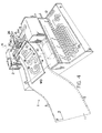
- a sign making machine 12 is illustrated for handling and working on an associated web 11 of laminated sheet material.
- the web 11 is moved through the machine 12 longitudinally of itself in the illustrated X coordinate direction by material advancing means 2 across a work surface defined by a roller 20.
- a tool head is supported and driven by appropriate motor means (not shown) in the illustrated Y coordinate direction on a way 13 extending transversely relative to the web 11.
- the machine 12 further includes a controller 7 having a microprocessing unit linked to a memory means and a keypad interface 25 for instructing the controller 7 to move the web 11 relative to the tool head 16 to cause a graphic 18 to be formed in the web 11.
- the advancing means includes two sprockets 14,14 rotatably driven by appropriate motor means about a common axis of rotation 65 in response to instructions issued by the controller 7.
- the sprockets 14,14 are spaced apart from one another by approximately the width of the web 11 and have a series of circumferentially disposed teeth or pins 15,15 projecting radially outwardly from the axis 65.
- the pins 15,15 are received within a series of openings 5,5 extending along either side edge of the web 11 in order to effect positive movement of the web 11 through the machine 12.
- Each of the sprockets has an associated arcuate clamp 31 joined with a pivotal support arm 30 biased toward the sprocket by a spring 32 drawing the clamp against the sheet material being pulled through the machine 12.
- the arcuately shaped guide clamps 31,31 each have an arcuate groove straddling the sprocket pins allowing the pins 15,15 to rotate through the clamps while nevertheless allowing each clamp to apply the hold down force necessary to keep the sheet material in registration with the sprockets.
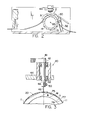
- the tool head 16 carries a tool holder 40 and an associated tool rotatable relative to the head about an axis 41 oriented substantially vertically when the tool head is in the working position above the web 11 as illustrated in Fig.
- the tool holder 40 has a chuck 48 for holding a cutting tool 46 for movement above the web 11 at the apex of the roller 20.
- the cutting tool 46 is a small scapula blade having a sharp cutting edge at its depending end and is clamped to the chuck 48 by means of a clamping screw 50 at its generally flat upper end.
- the chuck 48 and the associated cutting tool 46 are prevented from moving axially upwardly relative to the arm 44 by a detent ring 52 received within a circumaxial groove formed in the chuck 48.
- the chuck 48 is shown rotatably coupled by the belt 42, but may alternatively be freely rotatable about the tool axis 41 such that it is capable of repositioning itself along a line of cut as the directional movement of the web 11 is changed.
- the web 11 may be comprised of a sheet of sign material M and an underlying liner or base sheet L adhered to it.
- Each sheet has a relative thickness such that the materials allow the blade 46, with the appropriate adjustment of the counterweight 26, to cut the sheet material M while nevertheless only slightly scoring the liner L.
- the sign material sheet M has a cuttable upper sign surface 77 facing the tool head 16 and has an opposite lower surface 75 facing the liner sheet material L.
- the liner sheet material has an upper release surface R and an opposite lower surface 79 supportedly engaged by the roller 20.
- a layer T of pressure sensitive adhesive or permanently tacky adhesive releasably adhered to the release surface R of the liner sheet L, yet more strongly bonded to the lower surface 75 of the sign material sheet M.
- the adhesive layer T is however sufficiently strong enough to bond the cut graphic to a substrate surface in a manner consistent with that disclosed in the aforementioned U.S. Patent 4,467,525 issued to Logan et al.
- an automated weeding system indicated generally as 1 in Figure 4 is employed for readily removing weed portions W of the sign material sheet M from around and within the graphic 18 cut in it.
- the system 1 includes the aforementioned machine 12 which initially cuts the graphic 18 into the web 11, an overlay sheet 10 having means for placing it in registration with the cut web 11, a means 70 carried by the tool holder 40 for selectively bonding the overlay sheet 10 with portions of the sheet material M and a means within the controller 7 for causing the means 70 to follow a path slightly offset from the cut lines defining the graphic 18.
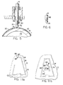
- the means 70 includes a pressing tool 72 having a depending tip 74 for engaging with the overlay sheet 10 to press it into bonding relationship with the underlying sign material sheet M in a manner that will be hereinafter become apparent.
- the pressing tool 72 at its upper end is sized to be received within the chuck 48 and may readily replace the cutting tool 46 by loosening the clamping screw 50 and reinserting the pressing tool 72 in its place.
- the overlay sheet 10 Interposed between the overlay sheet 10 and the web 11 is a bonding means 71 for selectively bonding to the overlay sheet 10 portions of the sign material sheet M directly underlying the tip 74 of the pressure tool 72.
- the overlay sheet 10 as illustrated in Fig. 7 may be comprised of a backing material O, preferably inexpensive paper having an upper surface 73 facing the tool 72 and an opposite lower surface 76 having a tacky adhesive layer A bonded to it.
- the adhesive layer A is a generally low tack adhesive with enough strength to hold the backing material O in place on the sign material sheet M.
- the adhesive layer A allows overlay sheet 10 to be held in registration with the web once it is placed onto the web for unitary movement therewith through the machine 12 as will hereinafter become apparent.
- each microsphere Embedded within the adhesive layer A however are a plurality of hollow microspheres C, within each is encapsulated a much stronger adhesive.
- each microsphere could contain a catalyst for activating the otherwise low tack adhesive layer A into an enhanced holding adhesive.
- the microspheres C contain a separate stronger adhesive and are of the type commercially available through the 3M Corporation having an 80% total weight payload fill of adhesive and a 20% total weight content comprised of shell.
- microspheres C are particularly well adapted for the purpose of automatic weeding because the microspheres C are crushable under the pressure tool 72 to effect enhanced bonding between the sheets O and M in regions exclusively beneath the tip 74 as can be appreciated from Figure 7.
- the relative adhesive bonding strengths and material thicknesses involved are selected such that the graphic 18 will remain adhered to the liner L while the weed portions W comprising the remaining sign material sheet M are pulled away with the overlay sheet 10 as will be discussed in greater detail with reference to Fig. 9.
- the controller 7 then instructs the material advancing means 2 to reverse the direction of the web 11 to position the initialization point S in registry with the cutting tool 46 (step 106). While maintaining registration of the web 11 with the sprockets 14,14, the overlay sheet 10 is placed down on the sign material sheet M (step 107) such that it completely covers the graphic 18 cut into the sign material sheet M. Since the overlay sheet width WD is shorter than that of the web 11, by for example approximately 2 inches, it does not interfere with the advancing means sprockets 31,31 thus allowing the adhesive layer A to maintain both the web 11 and the overlay sheet 10 in registration with one another for unitary movement through the machine 12.
- Fig. 10 shows an alternative embodiment of the cutting tool which may be employed by the weeding system 1.
- a combination pressure foot and knife holder assembly illustrated generally as 80 is used in place of the tool 72 thus avoiding the need to substitute the pressure tool 72 for the cutting implement 46.
- the assembly 80 is one such as disclosed in U.S. Patent No. 4,732,069 issued to Wood et al. on March 22, 1988 which patent being commonly assigned with the assignee of the present invention.
- the tool assembly 80 allows the graphic vectors stored in memory at step 104 to be recalled and used without alteration (step 114) to retrace the graphic 18 on the overlay sheet 10 thus mechanically creating the offset path 19.
- the assembly 80 comprises a body portion 89 having a depending portion 82 carrying a knife 84 and a pressure foot 86 offset laterally relative to the knife 84.
- the tip 88 of the knife projects downwardly from the pressure foot 86 by approximately 0.004 to 0.005 inch as indicated by the dimension Z. Because the tip 88 of the knife does not penetrate through or even substantially through the overlay sheet 10, the pressure foot 86 can thus be used to activate the underlying microcapsules C without causing the sheet O to be unduly cut up as the tool assembly 80 makes its second pass (step 116).
- the web 11' is comprised of a liner or base sheet L' bonded to a modified sheet of sign material M'.
- the sign material sheet M' has an upper surface 134 and an opposite lower surface 140 defining the good or the sign face of the sheet.
- the liner sheet L' has a layer of pressure sensitive or permanently tacky adhesive T' bonded more strongly to it than to the sign surface 140 of the sign material sheet M'.
- the sign surface 140 serves as a release surface allowing the adhesive layer T' to remain with the liner L' when the sign material sheet M' is pulled from it.
- the dry activatable adhesive K may take the form of a number of different types of activatable adhesives.
- the layer K is preferably a cured adhesive in which are embedded a plurality of crushable microcapsules of the type C disclosed with reference to Figure 7 above.
- the web 11' is preferably of the type disclosed in copending U.S. Serial No. 056,458, entitled SIGN MAKING WEB WITH DRY ADHESIVE LAYER AND METHOD OF USING THE SAME filed on May 29, 1987 in the name of the same inventor of the present invention and being commonly assigned therewith.
- the steps (110), (112) and (116) discussed previously with respect to Fig. 8 are then followed by the controller 7 causing the pressing tool 72 to be moved along the path 19'.
- the sign material defining the cut graphic may then be applied directly to the sign surface using the base sheet L according to the method disclosed in the aforementioned copending U.S. Application Serial No. 056,458.
- the dry activatable adhesive layer may alternatively take the form of an adhesive layer K' capable of being transformed into a tacky state by applying a liquid to it. As shown in Fig. 14, an applicator 90 having a depending tip 91 is filled with a liquid tackifier and replaces the cutting tool 46 for this purpose. While the activatable adhesive layer K' in this embodiment may take the form of a variety of different adhesives, the dry adhesive layer is preferably either rubber based or is water soluble.
- the applicator 90 is filled with a water based solution and in the example where the adhesive is rubber based, the applicator may be filled with a chemical tackifier, such as KODAFLEX Tx1B commercially made available by the Eastman Kodak Co., or other suitable activators, such as a di-2-ethyl hexyl phthalate solution.
- a chemical tackifier such as KODAFLEX Tx1B commercially made available by the Eastman Kodak Co.
- activators such as a di-2-ethyl hexyl phthalate solution.
- the applicator 90 when applying the tackifier in the manner shown in Fig. 14 follows the offset path created within the controller 7 as described with reference to step 112 in Fig 8.
- the tip 91 of the applicator 90 directly contacts the adhesive layer K' to activate it along underlying portions thereby forming a path 19' of tacky adhesive adjacent the graphic 18'.
- the overlay sheet O' need only be comprised of a sheet of material, preferably paper, having a sufficient size to be placed over the graphic 18 to bond it with the weed portions of the sign material sheet M' and to consequently allow the overlay sheet O to peel the weed portions from the liner L' when the two sheets are pulled apart.
- the adhesive layer K' in its tacky condition possesses a greater per unit peel strength taken relative to that of the tacky adhesive layer T' in accordance with the relative strengths set forth in table A-1 above.
- the automatic weeding system embodying the present invention employs the sign generating machine 12 and associated software for causing the holder 40 and the implement carried by it to be moved relative to the work surface 20 to not only cut a desired graphic into the web 11,11', but also to selectively tackify portions of the bonding means 71 into an activated adhesive.
- An overlay sheet 10 is provided for cooperating with the tackified portions of the bonding means such that the weed portions of the web 11 become bonded to the overlay sheet 10 for subsequent removal by the user.
- the overlay sheet 10 is either placed on the web 11 prior to the second pass made by a pressure tool as shown in Fig.
- the holder 40 may either carry two separate tools, one for cutting the web and the other for subsequently activating the bonding means 71 as illustrated in Figs. 5 and 6, or may carry a single tool which both cuts and activates without requiring tool replacement as is apparent from Fig 10.
- the overlay sheet 10,10' is used for removing the unwanted portions of the sign material sheet M,M' by pulling material which surrounds the graphic off the liner sheet material, it is possible to alternatively reverse the offset path followed by the pressure foot or tool so that the text adheres to the overlay sheet rather than to the weed portion so that it can be lifted off the backing leaving the weed on the original liner.
- the microencapsulated adhesive C is disclosed as being the preferred bonding means, it is entirely within the scope of the invention to substitute other known adhesives for this, such as for example, a thermally activated adhesive activated to a tacky condition by a heating element carried by the tool holder 40.
- the tool 72 may alternatively be an ultrasonic device moved along the overlay sheet in place on the sign material sheet to weld the two sheets together along a path.
Landscapes
- Life Sciences & Earth Sciences (AREA)
- Forests & Forestry (AREA)
- Engineering & Computer Science (AREA)
- Mechanical Engineering (AREA)
- Lining Or Joining Of Plastics Or The Like (AREA)
- Control Of Cutting Processes (AREA)
- Details Of Cutting Devices (AREA)
- Treatment Of Fiber Materials (AREA)
- Catching Or Destruction (AREA)
- Control And Other Processes For Unpacking Of Materials (AREA)
- Adhesive Tapes (AREA)
- Agricultural Chemicals And Associated Chemicals (AREA)
Applications Claiming Priority (3)
| Application Number | Priority Date | Filing Date | Title |
|---|---|---|---|
| US566123 | 1990-08-10 | ||
| US07/566,123 US5143576A (en) | 1990-08-10 | 1990-08-10 | Automatic weeding system and method of use |
| CA002056149A CA2056149C (fr) | 1990-08-10 | 1991-11-25 | Systeme de desherbage automatique et methode d'utilisation connexe |
Publications (2)
| Publication Number | Publication Date |
|---|---|
| EP0470645A1 true EP0470645A1 (fr) | 1992-02-12 |
| EP0470645B1 EP0470645B1 (fr) | 1994-06-29 |
Family
ID=25674868
Family Applications (1)
| Application Number | Title | Priority Date | Filing Date |
|---|---|---|---|
| EP91113470A Expired - Lifetime EP0470645B1 (fr) | 1990-08-10 | 1991-08-09 | Système automatique pour détacher des pièces découpées et procédé pour son application |
Country Status (7)
| Country | Link |
|---|---|
| US (2) | US5143576A (fr) |
| EP (1) | EP0470645B1 (fr) |
| JP (1) | JPH07276B2 (fr) |
| AT (1) | ATE107883T1 (fr) |
| AU (1) | AU630576B1 (fr) |
| CA (1) | CA2056149C (fr) |
| DE (1) | DE69102686T2 (fr) |
Cited By (4)
| Publication number | Priority date | Publication date | Assignee | Title |
|---|---|---|---|---|
| WO1994020311A1 (fr) * | 1993-03-12 | 1994-09-15 | Axel Donat | Feuille et procede de separation et de report de dessins decoupes dans une feuille adhesive |
| WO1997030855A1 (fr) * | 1996-02-24 | 1997-08-28 | Leonhard Kurz Gmbh & Co. | Film de transfert et son procede de production |
| ITFI20120232A1 (it) * | 2012-10-29 | 2014-04-30 | Esanastri S R L | Dispositivo di macro-sfridatura di film plastici o in carta a uno o più strati autoadesivi, biadesivizzati o elettrostatici accoppiati con un liner di supporto antiaderente |
| ITFI20120233A1 (it) * | 2012-10-29 | 2014-04-30 | Esanastri S R L | Dispositivo di micro-sfridatura di film plastici o in carta a uno o più strati autoadesivi, biadesivizzati o elettrostatici accoppiati con un liner di supporto antiaderente |
Families Citing this family (26)
| Publication number | Priority date | Publication date | Assignee | Title |
|---|---|---|---|---|
| US5288358A (en) * | 1987-05-29 | 1994-02-22 | Gerber Scientific Products, Inc. | Sign making web with dry adhesive layer and method of using the same |
| AU650636B2 (en) * | 1990-02-05 | 1994-06-30 | Molins Plc | Image applying method and apparatus |
| US5240539A (en) * | 1992-02-19 | 1993-08-31 | New Hermes Incorporated | Process for making three-dimensional signage |
| US5695600A (en) * | 1994-10-03 | 1997-12-09 | Goin; Bobby Gene | Vacuum table for decal weeding |
| US6102096A (en) * | 1997-05-30 | 2000-08-15 | Johansson; Goeran | Method and device for applying a pattern onto a support means |
| US6106645A (en) * | 1998-01-21 | 2000-08-22 | Gerber Scientific Products, Inc. | Method and apparatus for manufacturing a graphic product |
| ES2188439T3 (es) * | 2000-03-02 | 2003-07-01 | Gerber Scient Products Inc | Procedimiento y dispositivo para fabricar productos graficos. |
| USD453179S1 (en) | 2000-07-27 | 2002-01-29 | Iimak | Printer cassette |
| USD458295S1 (en) | 2000-07-27 | 2002-06-04 | Iimak | Printer cassette |
| US6582801B1 (en) | 2000-08-03 | 2003-06-24 | Optima Graphics, Inc. | Signage with opaque and transparent elements and method of making the same |
| US20020108477A1 (en) * | 2001-02-09 | 2002-08-15 | Seniff Dana W. | Method for cutting coating blankets from sheet-type work material |
| US6797103B2 (en) | 2001-03-12 | 2004-09-28 | Mikkelsen Graphic Engineering Inc. | Automatic waste-area removal method and apparatus |
| US6830645B2 (en) * | 2001-03-26 | 2004-12-14 | Appleton Papers Inc. | System and method for rupturing encapsulated adhesive in sheet media |
| EP1372961B1 (fr) * | 2001-03-26 | 2007-09-19 | Appleton Papers Inc. | Systeme et procede de rupture d'une colle encapsulee dans des supports en feuille |
| US7250092B2 (en) * | 2001-12-05 | 2007-07-31 | Ferrell Randall W | Adhesive sign and methods for applying and producing same |
| AT6638U1 (de) * | 2002-10-01 | 2004-01-26 | Gfm Gmbh | Verfahren zum ausschneiden eines zuschnittes aus einer textilen warenbahn zum herstellen von werkstücken aus einem faser-kunststoffverbund |
| US7140283B2 (en) * | 2004-05-05 | 2006-11-28 | Mikkelsen Graphic Engineering | Automated method and apparatus for vision registration of graphics areas operating from the unprinted side |
| USD527761S1 (en) | 2005-02-17 | 2006-09-05 | International Imaging Materials, Inc. | Printer cassette |
| US7930958B2 (en) | 2005-07-14 | 2011-04-26 | Provo Craft And Novelty, Inc. | Blade housing for electronic cutting apparatus |
| US20070012146A1 (en) * | 2005-07-14 | 2007-01-18 | Robert Workman | Electronic paper cutting apparatus and method |
| US7845259B2 (en) * | 2005-07-14 | 2010-12-07 | Provo Craft And Novelty, Inc. | Electronic paper cutting apparatus |
| US20090000437A1 (en) * | 2005-07-14 | 2009-01-01 | Provo Craft And Novelty, Inc. | Methods for Cutting |
| US20090025869A1 (en) * | 2005-09-27 | 2009-01-29 | Contra Vision Limited | Method Of Making A Vision Control Panel Using Cut Film |
| US7682476B2 (en) * | 2006-03-27 | 2010-03-23 | Ralph Sutton | Method to create 3-dimensional images from a 2-dimensional image |
| US20110280999A1 (en) | 2009-12-23 | 2011-11-17 | Provo Craft And Novelty, Inc. | Foodstuff Crafting Apparatus, Components, Assembly, and Method for Utilizing the Same |
| JP2013193193A (ja) * | 2012-03-22 | 2013-09-30 | Brother Industries Ltd | 切断装置 |
Citations (5)
| Publication number | Priority date | Publication date | Assignee | Title |
|---|---|---|---|---|
| US2907682A (en) * | 1958-05-28 | 1959-10-06 | Ncr Co | Adhesive tape containing pressurerupturable capsules |
| FR2525140A1 (fr) * | 1982-04-15 | 1983-10-21 | Gerber Garment Technology Inc | Procede de preparation d'une piece de patron |
| US4467525A (en) * | 1982-07-26 | 1984-08-28 | Gerber Scientific Products, Inc. | Automated sign generator |
| US4732069A (en) * | 1987-05-08 | 1988-03-22 | Gerber Scientific Products, Inc. | Knife and knife holder assembly |
| DE3818283A1 (de) * | 1987-05-29 | 1988-12-08 | Gerber Scient Products Inc | Bahn zur herstellung von zeichen und verfahren zu deren verwendung |
Family Cites Families (14)
| Publication number | Priority date | Publication date | Assignee | Title |
|---|---|---|---|---|
| US2591779A (en) * | 1948-04-13 | 1952-04-08 | By Buk Company | Sign and method of making the same |
| US3297508A (en) * | 1962-12-10 | 1967-01-10 | Meyercord Co | Dry strip decalcomania or transfer and method of use |
| DE1225490B (de) * | 1964-02-27 | 1966-09-22 | Heinrich Heichlinger | Material zur Herstellung von negativen Kopiervorlagen |
| US3741786A (en) * | 1971-05-28 | 1973-06-26 | Avery Products Corp | Transfer tape having non-contiguous pressure sensitive adhesive patterns |
| US3785898A (en) * | 1972-01-14 | 1974-01-15 | Gerber Garment Technology Inc | Apparatus for producing seamed articles from sheet material |
| GB2039785B (en) * | 1978-11-09 | 1983-04-13 | Sanyo Kokusaku Pulp Co | Pressure sensitive adhesive products and the method for preparation of the same |
| US4460634A (en) * | 1979-12-29 | 1984-07-17 | Masaaki Hasegawa | Adhesive sheet and method for manufacturing the same |
| GB2092521A (en) * | 1981-02-06 | 1982-08-18 | Letraset International Ltd | Production of artwork |
| US4444078A (en) * | 1982-02-04 | 1984-04-24 | Gerber Garment Technology, Inc. | Apparatus for cutting sheet material |
| US4512839A (en) * | 1982-10-29 | 1985-04-23 | Gerber Scientific, Inc. | Multi-color sign making method and layup |
| DE3501815C2 (de) * | 1985-01-21 | 1987-04-16 | D. Swarovski & Co., Wattens, Tirol | Verfahren zur Herstellung eines Dekormaterials |
| US4759816A (en) * | 1986-07-07 | 1988-07-26 | Schoeller Technical Papers, Inc. | Strippable film for adhesive coating and laminating |
| US4824498A (en) * | 1987-07-09 | 1989-04-25 | James River Corporation | Strippalble sponge cushion underlay for a surface covering, such as carpeting |
| US5116439A (en) * | 1989-02-13 | 1992-05-26 | Sponge-Cushion, Inc. | Method and product for floor covering installation and removal |
-
1990
- 1990-08-10 US US07/566,123 patent/US5143576A/en not_active Expired - Lifetime
-
1991
- 1991-08-09 DE DE69102686T patent/DE69102686T2/de not_active Expired - Fee Related
- 1991-08-09 EP EP91113470A patent/EP0470645B1/fr not_active Expired - Lifetime
- 1991-08-09 AT AT91113470T patent/ATE107883T1/de not_active IP Right Cessation
- 1991-08-12 JP JP3201918A patent/JPH07276B2/ja not_active Expired - Fee Related
- 1991-09-17 AU AU84561/91A patent/AU630576B1/en not_active Ceased
- 1991-11-25 CA CA002056149A patent/CA2056149C/fr not_active Expired - Fee Related
-
1992
- 1992-06-09 US US07/895,929 patent/US5277736A/en not_active Expired - Fee Related
Patent Citations (5)
| Publication number | Priority date | Publication date | Assignee | Title |
|---|---|---|---|---|
| US2907682A (en) * | 1958-05-28 | 1959-10-06 | Ncr Co | Adhesive tape containing pressurerupturable capsules |
| FR2525140A1 (fr) * | 1982-04-15 | 1983-10-21 | Gerber Garment Technology Inc | Procede de preparation d'une piece de patron |
| US4467525A (en) * | 1982-07-26 | 1984-08-28 | Gerber Scientific Products, Inc. | Automated sign generator |
| US4732069A (en) * | 1987-05-08 | 1988-03-22 | Gerber Scientific Products, Inc. | Knife and knife holder assembly |
| DE3818283A1 (de) * | 1987-05-29 | 1988-12-08 | Gerber Scient Products Inc | Bahn zur herstellung von zeichen und verfahren zu deren verwendung |
Cited By (9)
| Publication number | Priority date | Publication date | Assignee | Title |
|---|---|---|---|---|
| WO1994020311A1 (fr) * | 1993-03-12 | 1994-09-15 | Axel Donat | Feuille et procede de separation et de report de dessins decoupes dans une feuille adhesive |
| WO1997030855A1 (fr) * | 1996-02-24 | 1997-08-28 | Leonhard Kurz Gmbh & Co. | Film de transfert et son procede de production |
| US6059914A (en) * | 1996-02-24 | 2000-05-09 | Leonhard Kurz Gmbh & Co. | Process for the production of a stamping foil |
| ITFI20120232A1 (it) * | 2012-10-29 | 2014-04-30 | Esanastri S R L | Dispositivo di macro-sfridatura di film plastici o in carta a uno o più strati autoadesivi, biadesivizzati o elettrostatici accoppiati con un liner di supporto antiaderente |
| ITFI20120233A1 (it) * | 2012-10-29 | 2014-04-30 | Esanastri S R L | Dispositivo di micro-sfridatura di film plastici o in carta a uno o più strati autoadesivi, biadesivizzati o elettrostatici accoppiati con un liner di supporto antiaderente |
| WO2014068449A1 (fr) * | 2012-10-29 | 2014-05-08 | Esanastri S.R.L. | Dispositif destiné au dégagement fin d'une feuille multicouche comprenant un couchage de support et au moins un film adhésif couplé au couchage |
| WO2014087273A1 (fr) * | 2012-10-29 | 2014-06-12 | Esanastri S.R.L. | Dispositif destiné au dégagement grossier d'une feuille multicouche comprenant un revêtement de support et au moins un film adhésif accouplé au revêtement |
| US9434148B2 (en) | 2012-10-29 | 2016-09-06 | Esanastri S.R.L. | Device for the fine weeding of a multilayer sheet comprising a support liner and at least one adhesive film coupled with the liner |
| US9486931B2 (en) | 2012-10-29 | 2016-11-08 | Esanastri S.R.L. | Device for the rough weeding of a multilayer sheet comprising a support liner and at least one adhesive film coupled with the liner |
Also Published As
| Publication number | Publication date |
|---|---|
| CA2056149C (fr) | 1996-10-22 |
| US5277736A (en) | 1994-01-11 |
| AU630576B1 (en) | 1992-10-29 |
| EP0470645B1 (fr) | 1994-06-29 |
| CA2056149A1 (fr) | 1993-05-26 |
| JPH04250996A (ja) | 1992-09-07 |
| US5143576A (en) | 1992-09-01 |
| JPH07276B2 (ja) | 1995-01-11 |
| ATE107883T1 (de) | 1994-07-15 |
| DE69102686T2 (de) | 1994-12-15 |
| DE69102686D1 (de) | 1994-08-04 |
Similar Documents
| Publication | Publication Date | Title |
|---|---|---|
| EP0470645B1 (fr) | Système automatique pour détacher des pièces découpées et procédé pour son application | |
| JPH065115Y2 (ja) | パターン片作成装置 | |
| GB2130419A (en) | Multi-color sign making | |
| US6106645A (en) | Method and apparatus for manufacturing a graphic product | |
| US4364330A (en) | Cutting apparatus with consumable marker | |
| JPS63300892A (ja) | ナイフ及びナイフホルダ組立体 | |
| EP0295458A2 (fr) | Appareil pour ébavurer des produits moulés | |
| US20200349868A1 (en) | Multilayered sheet assembly and a method for forming a sign | |
| US5304410A (en) | Cutting cloth web having mounted backing material and related method | |
| JPS62198890A (ja) | 標識作成用の多層ウエブとその使用方法 | |
| JPH0356227A (ja) | 熱接着フィルムの接着装置 | |
| US5213656A (en) | Method of using a web for etching of a surface | |
| JP3524263B2 (ja) | 自動裁断機におけるマーキング方法およびマーキング装置 | |
| US4113538A (en) | Method of and means for mounting labels | |
| CA2056329A1 (fr) | Technique de fabrication d'enseigne utilisant des oeuvres graphiques adhesives deux faces et une couche de decoration appliquee subsequemment | |
| EP1129867B1 (fr) | Procédé et dispositif pour fabriquer des produits graphiques | |
| KR102911814B1 (ko) | 경사 가변 원뿔대 핫 스탬핑 장치 | |
| KR20260038330A (ko) | 원뿔대 형상 제품의 핫스탬핑 방법 및 그 장치 | |
| JP2696569B2 (ja) | 薄板の切断方法 | |
| JPH10139459A (ja) | ガラス切断に於ける製品ガラスの個別情報認識可能化処理方法と、その装置 | |
| JP2506700B2 (ja) | 微小物体の自動供給方法 | |
| US20020108477A1 (en) | Method for cutting coating blankets from sheet-type work material | |
| US6401616B1 (en) | Method and material for making a coating blanket for use in printing presses | |
| JP2004025356A (ja) | 切断装置 | |
| JP2756291B2 (ja) | マーク用布地等の切断装置 |
Legal Events
| Date | Code | Title | Description |
|---|---|---|---|
| PUAI | Public reference made under article 153(3) epc to a published international application that has entered the european phase |
Free format text: ORIGINAL CODE: 0009012 |
|
| 17P | Request for examination filed |
Effective date: 19911122 |
|
| AK | Designated contracting states |
Kind code of ref document: A1 Designated state(s): AT BE CH DE DK ES FR GB GR IT LI LU NL SE |
|
| 17Q | First examination report despatched |
Effective date: 19930316 |
|
| GRAA | (expected) grant |
Free format text: ORIGINAL CODE: 0009210 |
|
| AK | Designated contracting states |
Kind code of ref document: B1 Designated state(s): AT BE CH DE DK ES FR GB GR IT LI LU NL SE |
|
| PG25 | Lapsed in a contracting state [announced via postgrant information from national office to epo] |
Ref country code: NL Effective date: 19940629 Ref country code: LI Effective date: 19940629 Ref country code: GR Free format text: LAPSE BECAUSE OF FAILURE TO SUBMIT A TRANSLATION OF THE DESCRIPTION OR TO PAY THE FEE WITHIN THE PRESCRIBED TIME-LIMIT Effective date: 19940629 Ref country code: ES Free format text: THE PATENT HAS BEEN ANNULLED BY A DECISION OF A NATIONAL AUTHORITY Effective date: 19940629 Ref country code: DK Effective date: 19940629 Ref country code: CH Effective date: 19940629 Ref country code: BE Effective date: 19940629 |
|
| REF | Corresponds to: |
Ref document number: 107883 Country of ref document: AT Date of ref document: 19940715 Kind code of ref document: T |
|
| REF | Corresponds to: |
Ref document number: 69102686 Country of ref document: DE Date of ref document: 19940804 |
|
| ITF | It: translation for a ep patent filed | ||
| PG25 | Lapsed in a contracting state [announced via postgrant information from national office to epo] |
Ref country code: LU Free format text: LAPSE BECAUSE OF NON-PAYMENT OF DUE FEES Effective date: 19940831 |
|
| ET | Fr: translation filed | ||
| PG25 | Lapsed in a contracting state [announced via postgrant information from national office to epo] |
Ref country code: SE Effective date: 19940929 |
|
| REG | Reference to a national code |
Ref country code: CH Ref legal event code: PL |
|
| NLV1 | Nl: lapsed or annulled due to failure to fulfill the requirements of art. 29p and 29m of the patents act | ||
| PLBE | No opposition filed within time limit |
Free format text: ORIGINAL CODE: 0009261 |
|
| STAA | Information on the status of an ep patent application or granted ep patent |
Free format text: STATUS: NO OPPOSITION FILED WITHIN TIME LIMIT |
|
| 26N | No opposition filed | ||
| REG | Reference to a national code |
Ref country code: GB Ref legal event code: IF02 |
|
| PGFP | Annual fee paid to national office [announced via postgrant information from national office to epo] |
Ref country code: AT Payment date: 20020729 Year of fee payment: 12 |
|
| PG25 | Lapsed in a contracting state [announced via postgrant information from national office to epo] |
Ref country code: AT Free format text: LAPSE BECAUSE OF NON-PAYMENT OF DUE FEES Effective date: 20030809 |
|
| PGFP | Annual fee paid to national office [announced via postgrant information from national office to epo] |
Ref country code: GB Payment date: 20030814 Year of fee payment: 13 Ref country code: DE Payment date: 20030814 Year of fee payment: 13 |
|
| PGFP | Annual fee paid to national office [announced via postgrant information from national office to epo] |
Ref country code: FR Payment date: 20030819 Year of fee payment: 13 |
|
| PG25 | Lapsed in a contracting state [announced via postgrant information from national office to epo] |
Ref country code: GB Free format text: LAPSE BECAUSE OF NON-PAYMENT OF DUE FEES Effective date: 20040809 |
|
| PG25 | Lapsed in a contracting state [announced via postgrant information from national office to epo] |
Ref country code: DE Free format text: LAPSE BECAUSE OF NON-PAYMENT OF DUE FEES Effective date: 20050301 |
|
| GBPC | Gb: european patent ceased through non-payment of renewal fee |
Effective date: 20040809 |
|
| PG25 | Lapsed in a contracting state [announced via postgrant information from national office to epo] |
Ref country code: FR Free format text: LAPSE BECAUSE OF NON-PAYMENT OF DUE FEES Effective date: 20050429 |
|
| REG | Reference to a national code |
Ref country code: FR Ref legal event code: ST |
|
| PG25 | Lapsed in a contracting state [announced via postgrant information from national office to epo] |
Ref country code: IT Free format text: LAPSE BECAUSE OF NON-PAYMENT OF DUE FEES;WARNING: LAPSES OF ITALIAN PATENTS WITH EFFECTIVE DATE BEFORE 2007 MAY HAVE OCCURRED AT ANY TIME BEFORE 2007. THE CORRECT EFFECTIVE DATE MAY BE DIFFERENT FROM THE ONE RECORDED. Effective date: 20050809 |