EP0480066A1 - Procede de masquage - Google Patents
Procede de masquage Download PDFInfo
- Publication number
- EP0480066A1 EP0480066A1 EP91908565A EP91908565A EP0480066A1 EP 0480066 A1 EP0480066 A1 EP 0480066A1 EP 91908565 A EP91908565 A EP 91908565A EP 91908565 A EP91908565 A EP 91908565A EP 0480066 A1 EP0480066 A1 EP 0480066A1
- Authority
- EP
- European Patent Office
- Prior art keywords
- masking
- masking member
- belt conveyer
- members
- attaching means
- Prior art date
- Legal status (The legal status is an assumption and is not a legal conclusion. Google has not performed a legal analysis and makes no representation as to the accuracy of the status listed.)
- Withdrawn
Links
Images


Classifications
-
- B—PERFORMING OPERATIONS; TRANSPORTING
- B65—CONVEYING; PACKING; STORING; HANDLING THIN OR FILAMENTARY MATERIAL
- B65G—TRANSPORT OR STORAGE DEVICES, e.g. CONVEYORS FOR LOADING OR TIPPING, SHOP CONVEYOR SYSTEMS OR PNEUMATIC TUBE CONVEYORS
- B65G47/00—Article or material-handling devices associated with conveyors; Methods employing such devices
- B65G47/22—Devices influencing the relative position or the attitude of articles during transit by conveyors
-
- B—PERFORMING OPERATIONS; TRANSPORTING
- B05—SPRAYING OR ATOMISING IN GENERAL; APPLYING FLUENT MATERIALS TO SURFACES, IN GENERAL
- B05B—SPRAYING APPARATUS; ATOMISING APPARATUS; NOZZLES
- B05B12/00—Arrangements for controlling delivery; Arrangements for controlling the spray area
- B05B12/16—Arrangements for controlling delivery; Arrangements for controlling the spray area for controlling the spray area
- B05B12/20—Masking elements, i.e. elements defining uncoated areas on an object to be coated
- B05B12/26—Masking elements, i.e. elements defining uncoated areas on an object to be coated for masking cavities
Definitions
- the present invention relates to a method for masking wherein parts of the surface of an article are protected by masking members from a surface treatment.
- a protective paint such as a polyvinyl-chloride sol, a tar-urethane, and the like have been coated on the underside of the floor of cars for the purpose of corrosion, sound, and vibration proofing.
- the holes in said underside of the floor of cars should be protected by masking members that do not to stick to said protective paint on the insides or the surroundings of said holes, and said holes may be such as drainage holes, cable holes, bolt holes, parts penetrating holes and the like.
- More than 200 pieces of such masking members are attached in said coating of said underside of the floor of cars, and many trained workmen may be necessary to quickly attach such a large number of masking members to the places to be protected so as not to obstruct the car-manufacturing line.
- adhesive tape has been used as a masking member but in the case of adhesive tape, such adhesive tape has to be cut in pieces having suitable shapes and sizes. Whenever such adhesive tape is attached to a place to be protected and the thickness of said adhesive tape is small, said adhesive tape may be buried in the coating film and it is difficult to remove said adhesive tape from said place.
- masking members made of a foamed plastic such as a foamed polystyrene have been provided instead of said adhesive tape (Tokkai Sho 64-43376, Tokkai Sho 64-85171 etc).
- Said masking members made of foamed plastic may be easily modeled into suitable shapes, and the thickness of said masking members may be easily increased so that said masking members may be easily attached and removed to/from the places to be protected, and now an important problem is how to attach and remove said masking members to/from said places to be protected by employing a robot.
- each said masking member it may be considered to convey said masking member from the deposit spot of said masking member to the attaching spot by using a conveyer. Nevertheless, as the pick-up spot of the robot is fixed, it is necessary to fix said masking member on the conveyer so as it does not move from said fixed pick-up spot.
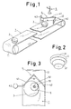
- the present invention provides a method for masking characterized by arranging set-position equipment at the pick-up spot of an attaching means (5) at the rear end of a belt conveyer (1) when masking members (3) are put on said belt conveyer (1) at the front end (11) and picked up by said attaching means (5) at the rear end (12) to attach said masking members (3) to the places to be protected, wherein said set-position equipment (4) consists of left and right wing panels (41), (42) or left and right guide bars (41)C, (42)C which open towards the front end of said belt conveyer (1).
- the masking members (3) are put on said conveyer (1) one by one at the front end to be conveyed to the pick-up spot of said attaching means (5) at the rear end.
- said masking members (3) are one by one set at the pick-up spot which is located at the rear most position of said set-position equipment (4) being guided by said left and right wing panels (41) , (42) or left and right guide bars (41)C, (42)C which open towards the front end (11) of said belt conveyer (1).
- said masking members (3) can be certainly picked up by said robot attaching means (5) one by one at the rear end (12) of said belt conveyer (1).
- the present invention it becomes possible to supply the masking members automatically and thus, the attaching process of the masking members can be performed fully-automatically.
- Figs. 1 to 7 show an embodiment of the present invention.
- Figs. 1 to 4 each show an embodiment of the present invention.
- (1) is a belt conveyer and a plug-type masking member (3) is put on the front end (11) of said belt conveyer (1) and picked up at the rear end (12) by said attaching means (5).
- Said masking member (3) is made of a plastic such as polystyrene, polyethylene, polypropylene, polyvinylchloride, polyurethane, melamine resin, urea resin, phenol resin and the like, a reinforced plastic wherein an inorganic filler such as calcium carbonate, talc, bentonite and the like is mixed in said plastic, a foamed plastic of said plastic, a synthetic rubber such as styrene-butadiene rubber, acrylonitrile-butadiene rubber and the like, a natural rubber, a molded fiber material wherein wood fiber, synthetic fiber, natural fiber, inorganic fiber etc.
- a plastic such as polystyrene, polyethylene, polypropylene, polyvinylchloride, polyurethane, melamine resin, urea resin, phenol resin and the like
- a reinforced plastic wherein an inorganic filler such as calcium carbonate, talc, bentonite and the like is mixed in said plastic
- a binder to mold wood, paper, reclaimed paper, corrugated card-board, metal, and a complex or a laminate of two or more of said materials, and as shown in Fig. 2, a flange part (31) is formed on the upperside of said masking member (3) and an inserting part (32) is formed on the lower side of said masking member (3).
- said masking members (3) are one by one put on the belt conveyer (1) at the front end (11).
- said masking members (3) are conveyed from the masking member depositing spot to the masking member attaching spot and said masking members (3) are one by one caught by the set-position equipment (4) at the rear end (12) of said belt conveyer (1) as shown in Fig. 3.
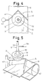
- said masking members (3) are one by one guided by said guide panels (41), (42) of said set-position equipment (4) and as shown in Fig. 4, said masking members (3) are finally and individually located at the rear-most position of said set-position equipment (4). Said position may be directly below said attaching means (5) . In this position, said masking members (3) slide on said belt conveyer (1). As shown in Fig.
- said attaching means (5) consists of a sucker (51) made of a flexible elastic material such as rubber, flexible plastic, and the like or a rigid material such as rigid plastic, metal, and the like, a supporting pipe (53) inserted into the attaching part (52) of said sucker (51), and a vacuum-ventilation tube (54) connected to said supporting pipe (53), and said attaching means (5) is equipped to a robot not shown in the Figures and said masking member (3) is put on said belt conveyer (1) and located right below said attaching means (5) and is picked up by said sucker (51) by vacuum-suction.
- said masking member (3) is attached in a hole (61) of an article (6) to be protected by inserting the inserting part (32) of said masking member (3) into said hole (61) as shown in Fig. 6 and air is allowed into said sucker (51) of said attaching means (5) through said vacuum-ventilation tube (54) to release said masking member (3) from said sucker (51).
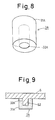
- Figs. 8 and 9 each show another embodiment of the masking member (3)A used in the present invention.
- said masking member (3)A has a structure wherein an inserting hole (32)A is formed in a cylinderical body (31)A.
- Said masking member (3)A is guided to the rear-most position of said set-position equipment (4) at the rear end (12) of said belt conveyer (1), the same as for the former embodiment and at this position, said masking member (3) is vacuum-sucked by said sucker (51) of said attaching means (5) and, as shown in Fig. 9, a boss (62) of an article (6) is covered with said masking member (3)A to protect said boss (62).
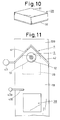
- Figs. 10 to 15 each show still another embodiment of the masking member (3)B used in the present invention.
- Said masking member (3)B has a structure wherein an adhesive layer (32)B is formed on the lower side of a panel body (31)B having a square shape as shown in the Figures.
- Said masking member (3)B may be put on a stick-proof belt conveyer (1)B on which a release agent is coated or a release sheet such as polyethlene sheet, polypropylene sheet, polyvinyl fluoride sheet, polyvinylidene fluoride and the like is covered and said masking member (3)B is guided to the rear-most position of said set-position equipment (4) the same as for the former embodiments, but since said masking member (3)B has a square shape as shown by the dotted line in Fig.
- said masking member (3)B should be put on said belt conveyer (1)B slanting from the longitudinal direction of said belt conveyer (1)B or said masking member (3)B may be caught between said guide panels (41), (42) and as a result it may be impossible to guide said masking member (3)B to the rear-most position of said set-position equipment (4).
- a correcting bar (41)B supported by a pole (43)B is arranged in front of said set-position equipment (4) to make said correcting bar (41)B come into contact with said masking member (3)B and give said masking member (3)B a slant from the longitudinal direction of said belt conveyer (1)B as shown in Fig. 12.
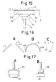
- said masking member (3)B can be guided by said guide panels (41), (42) without being caught as before described between said guide panels (41), (42) and as shown in Fig. 14, said masking member (3)B may be located at the rear-most position of said set-position equipment (4) right below said attaching means (5). Then said masking member (3)B is vacuum-sucked by said sucker (51) of said attaching means (5) and attached to a surface part (63) of an article (6) to be protected by said adhesive layer (32)B as shown in Fig. 15.
- said left and right wing panels (41)A and (42)A may be separated from each other as shown in Fig. 16, A and further, said left and right wing panels (41)B and (42)B may be connected together to form a U-shape as shown in Fig. 16, B. Further, to guide said masking member smoothly, a preferable angle between said left wing and right wing may be less than 90°. Still further, in the case of a masking member in which the plane shape is a circle, a pair of guide bars (41)C and (42)C may be arranged on the left side and right side as shown in Fig. 16, C.
- a pinch-type attaching means (5)A as shown in Fig. 17, A, a needle type attaching means (5)B as shown in Fig. 17, B and the like may be provided as the attaching means to pick-up said masking member (3).
Landscapes
- Engineering & Computer Science (AREA)
- Mechanical Engineering (AREA)
- Details Or Accessories Of Spraying Plant Or Apparatus (AREA)
- Application Of Or Painting With Fluid Materials (AREA)
Abstract
Un objectif de cette invention est d'effectuer aisément le montage rapide et automatique d'une multiplicité de matériaux de masquage. Pour cela, les matériaux de masquage sont mis en position sur un transporteur à courroie par l'intermédiaire d'un élément de guidage afin de transporter en succession les matériaux de masquage sur le transporteur à courroie jusqu'à un dispositif de montage en position de ramassage, de sorte que les matériaux de masquage peuvent être attrapés avec précision par le dispositif de montage.
Applications Claiming Priority (2)
| Application Number | Priority Date | Filing Date | Title |
|---|---|---|---|
| JP2110820A JPH0440261A (ja) | 1990-04-26 | 1990-04-26 | マスキング方法 |
| JP110820/90 | 1990-04-26 |
Publications (2)
| Publication Number | Publication Date |
|---|---|
| EP0480066A1 true EP0480066A1 (fr) | 1992-04-15 |
| EP0480066A4 EP0480066A4 (en) | 1993-04-21 |
Family
ID=14545491
Family Applications (1)
| Application Number | Title | Priority Date | Filing Date |
|---|---|---|---|
| EP19910908565 Withdrawn EP0480066A4 (en) | 1990-04-26 | 1991-04-25 | Method of masking |
Country Status (4)
| Country | Link |
|---|---|
| EP (1) | EP0480066A4 (fr) |
| JP (1) | JPH0440261A (fr) |
| CA (1) | CA2062960A1 (fr) |
| WO (1) | WO1991016147A1 (fr) |
Cited By (6)
| Publication number | Priority date | Publication date | Assignee | Title |
|---|---|---|---|---|
| FR2694079A1 (fr) * | 1992-07-23 | 1994-01-28 | Gerard Gonda | Dispositif d'enfournement - déplacement - et défournement de produits à cuire, sécher, coller ou autres. |
| EP0853982A3 (fr) * | 1997-01-15 | 2001-12-12 | STAHLSCHMIDT & MAIWORM GmbH | Méthode et appareil pour couvrier les trous de fixation d'une roue |
| WO2007108740A1 (fr) * | 2006-03-20 | 2007-09-27 | Törestorps Tråd Ab | Appareil de masquage, procédé de fabrication de l'appareil et son utilisation |
| WO2019170427A1 (fr) * | 2018-03-05 | 2019-09-12 | Mimot Gmbh | Dispositif pour le centrage de bobines de ceinture logeant des composants électriques |
| CN112387454A (zh) * | 2020-10-26 | 2021-02-23 | 王永进 | 喷涂机构用输送装置、纤维加工用助剂瓶的瓶体喷涂方法 |
| CN112387455A (zh) * | 2020-10-26 | 2021-02-23 | 王永进 | 喷涂机构及其在纺织品加工用助剂瓶上的应用 |
Families Citing this family (2)
| Publication number | Priority date | Publication date | Assignee | Title |
|---|---|---|---|---|
| CN105438780B (zh) * | 2015-12-16 | 2018-10-30 | 嵊州市银海机械有限公司 | 一种应用于金属件的下料检测设备 |
| CN107720236A (zh) * | 2017-11-13 | 2018-02-23 | 李紫熠 | 一种传送带物料阻隔机构 |
Family Cites Families (3)
| Publication number | Priority date | Publication date | Assignee | Title |
|---|---|---|---|---|
| NL6802703A (fr) * | 1968-02-26 | 1969-08-28 | ||
| DE3437836A1 (de) * | 1984-10-16 | 1986-04-17 | August Läpple GmbH & Co, 7100 Heilbronn | Handhabungsgeraet |
| JPS63171661A (ja) * | 1987-01-12 | 1988-07-15 | Toyota Motor Corp | マスク部材取外し装置 |
-
1990
- 1990-04-26 JP JP2110820A patent/JPH0440261A/ja active Pending
-
1991
- 1991-04-25 WO PCT/JP1991/000566 patent/WO1991016147A1/fr not_active Ceased
- 1991-04-25 CA CA002062960A patent/CA2062960A1/fr not_active Abandoned
- 1991-04-25 EP EP19910908565 patent/EP0480066A4/en not_active Withdrawn
Cited By (6)
| Publication number | Priority date | Publication date | Assignee | Title |
|---|---|---|---|---|
| FR2694079A1 (fr) * | 1992-07-23 | 1994-01-28 | Gerard Gonda | Dispositif d'enfournement - déplacement - et défournement de produits à cuire, sécher, coller ou autres. |
| EP0853982A3 (fr) * | 1997-01-15 | 2001-12-12 | STAHLSCHMIDT & MAIWORM GmbH | Méthode et appareil pour couvrier les trous de fixation d'une roue |
| WO2007108740A1 (fr) * | 2006-03-20 | 2007-09-27 | Törestorps Tråd Ab | Appareil de masquage, procédé de fabrication de l'appareil et son utilisation |
| WO2019170427A1 (fr) * | 2018-03-05 | 2019-09-12 | Mimot Gmbh | Dispositif pour le centrage de bobines de ceinture logeant des composants électriques |
| CN112387454A (zh) * | 2020-10-26 | 2021-02-23 | 王永进 | 喷涂机构用输送装置、纤维加工用助剂瓶的瓶体喷涂方法 |
| CN112387455A (zh) * | 2020-10-26 | 2021-02-23 | 王永进 | 喷涂机构及其在纺织品加工用助剂瓶上的应用 |
Also Published As
| Publication number | Publication date |
|---|---|
| EP0480066A4 (en) | 1993-04-21 |
| WO1991016147A1 (fr) | 1991-10-31 |
| JPH0440261A (ja) | 1992-02-10 |
| CA2062960A1 (fr) | 1991-10-27 |
Similar Documents
| Publication | Publication Date | Title |
|---|---|---|
| EP0480066A1 (fr) | Procede de masquage | |
| USRE40885E1 (en) | Robotic tape applicator and method | |
| US5270085A (en) | Masking member | |
| JPH07508251A (ja) | カバーストリップを有する搬送テープ | |
| CA1280648C (fr) | Methode pour lutter contre la corrosion, la transmission des bruits, et les vibrations dans une structure metallique | |
| CA1190739A (fr) | Support pour pieces dans une cabine de pistolage electrostatique | |
| EP0384695B1 (fr) | Elément de cache | |
| US5193716A (en) | Masking method | |
| US6007172A (en) | Drawer slide protector | |
| EP0509100A1 (fr) | Materiau de masquage | |
| EP0384696B1 (fr) | Elément de cache | |
| JPH0411972A (ja) | マスキング方法 | |
| EP0400667A2 (fr) | Outil et procédé de masquage | |
| EP0483377A1 (fr) | Materiau de masquage | |
| EP0401042B1 (fr) | Groupe d'éléments de masquage et méthode pour les fixer | |
| EP0384619A1 (fr) | Dispositif de masquage | |
| CA2060516A1 (fr) | Elements de masquage pouvant etre raccordes en serie | |
| EP0387998A1 (fr) | Dispositif de masquage | |
| EP0370796A1 (fr) | Procédé d'insonorisation et d'isolation contre la corrosion et les vibrations de structures métalliques | |
| JPH03240991A (ja) | マスキング材の着脱方法 | |
| CA2058305A1 (fr) | Ventouse | |
| JPH04161270A (ja) | マスキング方法 | |
| JPH0123570Y2 (fr) | ||
| JPH03221168A (ja) | 表面処理方法 | |
| DE68915978D1 (de) | Verfahren zum Tiefziehen eines Gegenstandes aus einer thermoplastischen Folie. |
Legal Events
| Date | Code | Title | Description |
|---|---|---|---|
| PUAI | Public reference made under article 153(3) epc to a published international application that has entered the european phase |
Free format text: ORIGINAL CODE: 0009012 |
|
| 17P | Request for examination filed |
Effective date: 19911227 |
|
| AK | Designated contracting states |
Kind code of ref document: A1 Designated state(s): DE FR GB IT SE |
|
| A4 | Supplementary search report drawn up and despatched |
Effective date: 19930304 |
|
| AK | Designated contracting states |
Kind code of ref document: A4 Designated state(s): DE FR GB IT SE |
|
| STAA | Information on the status of an ep patent application or granted ep patent |
Free format text: STATUS: THE APPLICATION IS DEEMED TO BE WITHDRAWN |
|
| 18D | Application deemed to be withdrawn |
Effective date: 19930609 |