EP0510686A2 - Automate d'analyse lisant les données associées aux récipients et méthode de manipulation des réactifs dans cet automate - Google Patents
Automate d'analyse lisant les données associées aux récipients et méthode de manipulation des réactifs dans cet automate Download PDFInfo
- Publication number
- EP0510686A2 EP0510686A2 EP92107052A EP92107052A EP0510686A2 EP 0510686 A2 EP0510686 A2 EP 0510686A2 EP 92107052 A EP92107052 A EP 92107052A EP 92107052 A EP92107052 A EP 92107052A EP 0510686 A2 EP0510686 A2 EP 0510686A2
- Authority
- EP
- European Patent Office
- Prior art keywords
- reagent
- data
- container
- analyzing apparatus
- reagents
- Prior art date
- Legal status (The legal status is an assumption and is not a legal conclusion. Google has not performed a legal analysis and makes no representation as to the accuracy of the status listed.)
- Granted
Links
Images
Classifications
-
- G—PHYSICS
- G01—MEASURING; TESTING
- G01N—INVESTIGATING OR ANALYSING MATERIALS BY DETERMINING THEIR CHEMICAL OR PHYSICAL PROPERTIES
- G01N35/00—Automatic analysis not limited to methods or materials provided for in any single one of groups G01N1/00 - G01N33/00; Handling materials therefor
- G01N35/00584—Control arrangements for automatic analysers
- G01N35/00594—Quality control, including calibration or testing of components of the analyser
- G01N35/00613—Quality control
- G01N35/00663—Quality control of consumables
-
- G—PHYSICS
- G01—MEASURING; TESTING
- G01N—INVESTIGATING OR ANALYSING MATERIALS BY DETERMINING THEIR CHEMICAL OR PHYSICAL PROPERTIES
- G01N35/00—Automatic analysis not limited to methods or materials provided for in any single one of groups G01N1/00 - G01N33/00; Handling materials therefor
- G01N35/10—Devices for transferring samples or any liquids to, in, or from, the analysis apparatus, e.g. suction devices, injection devices
- G01N35/1002—Reagent dispensers
-
- G—PHYSICS
- G06—COMPUTING OR CALCULATING; COUNTING
- G06K—GRAPHICAL DATA READING; PRESENTATION OF DATA; RECORD CARRIERS; HANDLING RECORD CARRIERS
- G06K7/00—Methods or arrangements for sensing record carriers, e.g. for reading patterns
- G06K7/0008—General problems related to the reading of electronic memory record carriers, independent of its reading method, e.g. power transfer
-
- G—PHYSICS
- G06—COMPUTING OR CALCULATING; COUNTING
- G06K—GRAPHICAL DATA READING; PRESENTATION OF DATA; RECORD CARRIERS; HANDLING RECORD CARRIERS
- G06K7/00—Methods or arrangements for sensing record carriers, e.g. for reading patterns
- G06K7/10—Methods or arrangements for sensing record carriers, e.g. for reading patterns by electromagnetic radiation, e.g. optical sensing; by corpuscular radiation
- G06K7/10544—Methods or arrangements for sensing record carriers, e.g. for reading patterns by electromagnetic radiation, e.g. optical sensing; by corpuscular radiation by scanning of the records by radiation in the optical part of the electromagnetic spectrum
- G06K7/10821—Methods or arrangements for sensing record carriers, e.g. for reading patterns by electromagnetic radiation, e.g. optical sensing; by corpuscular radiation by scanning of the records by radiation in the optical part of the electromagnetic spectrum further details of bar or optical code scanning devices
- G06K7/10861—Methods or arrangements for sensing record carriers, e.g. for reading patterns by electromagnetic radiation, e.g. optical sensing; by corpuscular radiation by scanning of the records by radiation in the optical part of the electromagnetic spectrum further details of bar or optical code scanning devices sensing of data fields affixed to objects or articles, e.g. coded labels
-
- G—PHYSICS
- G01—MEASURING; TESTING
- G01N—INVESTIGATING OR ANALYSING MATERIALS BY DETERMINING THEIR CHEMICAL OR PHYSICAL PROPERTIES
- G01N35/00—Automatic analysis not limited to methods or materials provided for in any single one of groups G01N1/00 - G01N33/00; Handling materials therefor
- G01N35/00584—Control arrangements for automatic analysers
- G01N35/00594—Quality control, including calibration or testing of components of the analyser
- G01N35/00613—Quality control
- G01N35/00663—Quality control of consumables
- G01N2035/00673—Quality control of consumables of reagents
-
- G—PHYSICS
- G01—MEASURING; TESTING
- G01N—INVESTIGATING OR ANALYSING MATERIALS BY DETERMINING THEIR CHEMICAL OR PHYSICAL PROPERTIES
- G01N35/00—Automatic analysis not limited to methods or materials provided for in any single one of groups G01N1/00 - G01N33/00; Handling materials therefor
- G01N35/00584—Control arrangements for automatic analysers
- G01N35/00722—Communications; Identification
- G01N35/00732—Identification of carriers, materials or components in automatic analysers
- G01N2035/00742—Type of codes
- G01N2035/00752—Type of codes bar codes
-
- G—PHYSICS
- G01—MEASURING; TESTING
- G01N—INVESTIGATING OR ANALYSING MATERIALS BY DETERMINING THEIR CHEMICAL OR PHYSICAL PROPERTIES
- G01N35/00—Automatic analysis not limited to methods or materials provided for in any single one of groups G01N1/00 - G01N33/00; Handling materials therefor
- G01N35/02—Automatic analysis not limited to methods or materials provided for in any single one of groups G01N1/00 - G01N33/00; Handling materials therefor using a plurality of sample containers moved by a conveyor system past one or more treatment or analysis stations
- G01N35/04—Details of the conveyor system
- G01N2035/0439—Rotary sample carriers, i.e. carousels
- G01N2035/0441—Rotary sample carriers, i.e. carousels for samples
-
- G—PHYSICS
- G01—MEASURING; TESTING
- G01N—INVESTIGATING OR ANALYSING MATERIALS BY DETERMINING THEIR CHEMICAL OR PHYSICAL PROPERTIES
- G01N35/00—Automatic analysis not limited to methods or materials provided for in any single one of groups G01N1/00 - G01N33/00; Handling materials therefor
- G01N35/02—Automatic analysis not limited to methods or materials provided for in any single one of groups G01N1/00 - G01N33/00; Handling materials therefor using a plurality of sample containers moved by a conveyor system past one or more treatment or analysis stations
- G01N35/04—Details of the conveyor system
- G01N2035/0439—Rotary sample carriers, i.e. carousels
- G01N2035/0443—Rotary sample carriers, i.e. carousels for reagents
-
- G—PHYSICS
- G01—MEASURING; TESTING
- G01N—INVESTIGATING OR ANALYSING MATERIALS BY DETERMINING THEIR CHEMICAL OR PHYSICAL PROPERTIES
- G01N35/00—Automatic analysis not limited to methods or materials provided for in any single one of groups G01N1/00 - G01N33/00; Handling materials therefor
- G01N35/02—Automatic analysis not limited to methods or materials provided for in any single one of groups G01N1/00 - G01N33/00; Handling materials therefor using a plurality of sample containers moved by a conveyor system past one or more treatment or analysis stations
- G01N35/04—Details of the conveyor system
- G01N2035/0439—Rotary sample carriers, i.e. carousels
- G01N2035/0451—Rotary sample carriers, i.e. carousels composed of interchangeable sectors
-
- G—PHYSICS
- G01—MEASURING; TESTING
- G01N—INVESTIGATING OR ANALYSING MATERIALS BY DETERMINING THEIR CHEMICAL OR PHYSICAL PROPERTIES
- G01N35/00—Automatic analysis not limited to methods or materials provided for in any single one of groups G01N1/00 - G01N33/00; Handling materials therefor
- G01N35/10—Devices for transferring samples or any liquids to, in, or from, the analysis apparatus, e.g. suction devices, injection devices
- G01N35/1009—Characterised by arrangements for controlling the aspiration or dispense of liquids
- G01N2035/1025—Fluid level sensing
-
- G—PHYSICS
- G01—MEASURING; TESTING
- G01N—INVESTIGATING OR ANALYSING MATERIALS BY DETERMINING THEIR CHEMICAL OR PHYSICAL PROPERTIES
- G01N35/00—Automatic analysis not limited to methods or materials provided for in any single one of groups G01N1/00 - G01N33/00; Handling materials therefor
- G01N35/10—Devices for transferring samples or any liquids to, in, or from, the analysis apparatus, e.g. suction devices, injection devices
- G01N35/1081—Devices for transferring samples or any liquids to, in, or from, the analysis apparatus, e.g. suction devices, injection devices characterised by the means for relatively moving the transfer device and the containers in an horizontal plane
- G01N35/1083—Devices for transferring samples or any liquids to, in, or from, the analysis apparatus, e.g. suction devices, injection devices characterised by the means for relatively moving the transfer device and the containers in an horizontal plane with one horizontal degree of freedom
- G01N2035/1086—Cylindrical, e.g. variable angle
-
- G—PHYSICS
- G01—MEASURING; TESTING
- G01N—INVESTIGATING OR ANALYSING MATERIALS BY DETERMINING THEIR CHEMICAL OR PHYSICAL PROPERTIES
- G01N35/00—Automatic analysis not limited to methods or materials provided for in any single one of groups G01N1/00 - G01N33/00; Handling materials therefor
- G01N35/02—Automatic analysis not limited to methods or materials provided for in any single one of groups G01N1/00 - G01N33/00; Handling materials therefor using a plurality of sample containers moved by a conveyor system past one or more treatment or analysis stations
- G01N35/025—Automatic analysis not limited to methods or materials provided for in any single one of groups G01N1/00 - G01N33/00; Handling materials therefor using a plurality of sample containers moved by a conveyor system past one or more treatment or analysis stations having a carousel or turntable for reaction cells or cuvettes
-
- G—PHYSICS
- G01—MEASURING; TESTING
- G01N—INVESTIGATING OR ANALYSING MATERIALS BY DETERMINING THEIR CHEMICAL OR PHYSICAL PROPERTIES
- G01N35/00—Automatic analysis not limited to methods or materials provided for in any single one of groups G01N1/00 - G01N33/00; Handling materials therefor
- G01N35/10—Devices for transferring samples or any liquids to, in, or from, the analysis apparatus, e.g. suction devices, injection devices
- G01N35/1065—Multiple transfer devices
Definitions
- the present invention relates to an automatic analyzing apparatus and a method of handling reagents employed in the automatic analyzing apparatus. More particularly, the present invention pertains to an automatic analyzing apparatus and a reagent handling method which are suitable for use when data on a liquid contained in a container, which is inscribed on the container, is read.
- reagents are supplied to the reaction container from a reagent container by a reagent delivery device.
- each of the containers has identification data, such as a bar code, and the data of each of the containers is read correspondingly to the position of that container.
- identification data such as a bar code
- Japanese Patent Unexamined Publication Nos. 62-95464, 61-68562 and 59-226865 implies the reading of the data on all of the reagent containers before reagents are delivered to reaction containers.
- the present invention provides an automatic analyzing apparatus which is designed to automatically read the data attached to a container loaded in a container housing unit without troubling the operator.
- the container data reading operation by a reading device is initiated by a detection signal obtained when an opening of the container housing unit is closed by a lid.
- the present invention further provides an automatic analyzing apparatus which is designed to prevent troubles of the analyzing apparatus which would occur when inadequate reagent containers are provided in a reagent accommodating portion.
- the types of reagents which are to be loaded in the reagent container accommodating portion are registered beforehand. When the reagent container whose data is read by the reading device does not correspond to the registered ones, the reagent delivery device is not activated.
- the operator of the automatic analyzing apparatus loads reagent containers in the reagent container housing unit in a preparation stage before the analysis operation by the analyzing apparatus begins. After the operator has loaded necessary reagent containers or replaced the reagent containers with new ones, he/she closes the opening of the housing unit with a lid. Closing of the lid produces a detection signal which initiates the reading operation of the data reading device. Thus, the reading operation can be reliably started without troubling the operator after the reagent containers have been loaded.
- reagents In an automatic analyzing apparatus in which analysis is performed on multiple inspection items, many types of reagents are used, or two, three or four types of reagents may be used for one analysis item.
- the first and second reagents regarding the same analysis item are loaded separately, for example, on different rows, because they are added to the reaction container at different times. However, the operator may misplace the first reagent at the position of the second reagent and vice versa.
- Misplacement of the first and second reagents can be checked by registering the types of reagents that can be loaded in the reagent accommodating portion beforehand, by reading the data on the reagent containers loaded in the accommodating portion and then by performing collation on these two data items.
- inadequate reagents are loaded, at least the reagent delivery device is locked to prevent troubles.
- the operator can notice the abnormality before the continuous analysis operation begins.
- inadequate reagents are displayed on a screen.
- the analyzing apparatus can recommend the operator replacement of the inadequate reagents with correct ones. After the inadequate reagents have been replaced, the reagent delivery device is unlocked, and the automatic analyzing apparatus initiates continuous analysis operation.
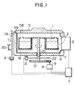
- FIG. 1 illustrates the structure of a reagent container housing unit.
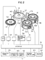
- reaction containers 15 are disposed on a reaction disk 50 which is intermittently driven by a driving unit 53 such that each of the reaction containers 15 crosses an optical path of a photometer 18.
- the reaction containers 15 are correspondent to the analysis items on which reaction should take place.
- the driving unit 52 is controlled by a control unit 11 through an interface 61.
- Sample containers 52 are disposed on a sample disk 13 rotated by a driving unit 54 in such a manner that they can be stopped at a sample picking position one by one.
- the blood serum contained in each of the sample containers 52 is delivered by a sample pipetting mechanism 14 into the same number of reaction containers 15 as the number of required analysis items.
- First and second reagents are added to each of the reaction containers 15 from two reagent supply systems at predetermined times.
- Third and fourth reagents may be added in addition to the first and second reagents, depending on the analysis items.
- the photometer 18 measures the liquid in the reaction container in which reaction between the sample and the reagents has completed.
- An analog signal obtained by photometry is converted into a digital signal by an analog/digital converter 55, and the converted signal is input to an operating unit 60 which operates the concentration or active value for each of the analysis items.
- the results of the operations are output by a printer 64. When necessary, they are displayed by a display unit 63, such as a CRT.
- the analysis apparatus shown in Fig. 2 has at least two reagent supply systems.
- a large number of first reagent containers 1A are provided on a reagent disk 16A.
- a desired reagent is delivered to the corresponding reaction container 15 on the reaction disk at a desired time by a first reagent pipetting mechanism 17A.
- the second reagent supply system when a desired one in a large number of second reagent containers 1B provided on a reagent disk 16B is located at a reagent picking position, the reagent in that desired container is delivered to the corresponding reaction container 15 by a second reagent pipetting mechanism 17B.
- Each of the reagent containers 1A and 1B has data on the liquid contained therein inscribed on the outer wall thereof.
- Examples of the data include the corresponding analysis item, the type of the reagent, the size of the reagent container, manufacturer's lot number and so on. Inscription may be made by digits, symbols or bar codes. In this embodiment, bar code notation is used. Although a bar code may be directly printed on the outer wall of each of the containers, a bar code label is generally pasted on a predetermined position of the container.
- Each of the reagent disks 16A and 16B is rotated by a corresponding driving unit 8 such that a desired reagent container 1A or 1B is located at the reagent picking position. While the disk 16A or 16B is at a stop, a reagent delivery system picks a predetermined amount of reagent.
- the reagent delivery system has the reagent pipetting mechanisms 17A and 17B and corresponding delivery mechanism driving units 56 which are controlled by a control unit 11.
- Each of the reagent pipetting mechanisms 17A and 17B has a pipette probe having a liquid level sensor. After the picked reagent is discharged into the corresponding reaction container 15, each of the pipette probes is washed by a corresponding pipette washing unit.
- a stirring mechanism 57 stirs the liquid in the reaction container with the reagent added thereto.
- FIG. 2 illustrates the reagent supply system comprising a combination of the movable reagent containers and the pipetting mechanisms.
- a reagent delivery system comprising a combination of stationary reagent containers and a dispenser mechanism may also be adopted.
- the reaction container 15 on which photometry has been conducted is washed by a washing mechanism 45 before it is supplied for a new sample analysis.
- Data reading devices 3A and 3B each consisting of a bar code reader, are disposed near the reagent disks 16A and 16B shown in Fig. 2 in such a manner that they face the corresponding disks to read the data printed in the form of bar codes.
- the results of the reading are stored in a storing unit 62 of the control unit 11 correspondingly to the position of each of the reagent containers 1A and 1B on the reagent disks 16A and 16B.
- Each of the reagent container accommodating portions includes a reagent container housing unit 7 made of a heat insulating material, and a lid 5 which closes an opening thereof, as shown in Fig. 1.
- a reagent container housing unit 7 made of a heat insulating material
- a lid 5 which closes an opening thereof, as shown in Fig. 1.
- illustration of such a reagent container accommodating portion is omitted to simplify the description.
- the reagent containers 1A each with a bar code label 2 are placed on a movable retainer 16 disposed within the container housing unit 7.
- the container housing unit 7 has at its upper portion an opening through which the reagent containers are supplied to or discharged from the unit.
- the opening is normally closed by the lid 5 made of an insulating material.
- the lid 5 has a through-hole 58 at a position where it faces the reagent picking position.
- the pipette probe of the reagent pipetting mechanism 17A enters or leaves the container housing unit 7 through the through-hole 58.
- the lid 5 is locked by a shaft 59 in such a manner as to be openable. Opening of the lid lowers a member 19.
- the distal end of the member 19 interrupts the optical path of a photo coupler 4 which is a detector.
- a resultant interrupt signal is transmitted to the control unit 11.
- the opened state of the lid 5 is maintained by a spring 20.
- the distal end of the member 19 retracts from the photo coupler 4, and the light from a light source in the photo coupler 4 thus reaches a receiving side.
- the resultant detection signal representing closing of the lid is also transmitted to the control unit 11.
- the container housing unit 7 forms a cold reserving unit. This is achieved by disposing a cooling plate 6 on the inner wall thereof.
- a rotary shaft 70 of the movable retainer 16 has a disk-shaped gear 10 which is in mesh with a gear 9.
- a driving force of a stepping motor 8, which is a driving unit controlled by the control unit 11 is transmitted to the disk-shaped gear 10 through the gear 9.
- a disk-shaped detecting plate 22 is provided on the rotary shaft 70.
- An angular position of the detecting plate 22 is detected by a position detector 21 which may be a photo coupler.
- the detection signal is transmitted to the control unit 11.
- a detecting plate 22 of the type which has detection holes in the disk, disclosed in Japanese Patent Publication No. 1-21910, may be employed.
- the position of the movable retainer 16 is determined on the basis of detection of the detection hole corresponding to each of the reagent containers.
- the bar code readers 3A and 3B are mounted on the side wall of the container housing
- the operator inputs from the operation panel 64 inspection items designated for each of the samples, and thereby stores the analysis items correspondingly to the sample numbers in the storing unit 62 of the control unit 11. Consequently, the reagents required for each of the analysis items are selected from the reagent table in the storing unit 62, and are separated and registered in first and second reagent registration portions. The registered reagents are stored in the storing unit 62. The reagent registration status is displayed, if the corresponding reagent containers are not placed on the reagent disk 13, on a screen display unit 63 in red.
- the first reagents are displayed in a group corresponding to the first reagent disk 16A, while the second reagents are displayed in a group corresponding to the second reagent disk 16B. If the first reagents are erroneously placed on the second reagent disk 16B, an alarm is issued while such first reagents are displayed in red on the display screen.
- the operator opens the lid 5 of each of the first and second reagent container housing units 7 and places the reagent containers 1A and 1B required for measurements of the inspection items on the movable retainer 16 from the opening.
- the operator closes the lid 5. Closing of the lid 5 allows the opening/closing detector 4 to output the detection signal to the control unit 11.
- the control unit 11 gives the operation starting instruction to the bar code readers 3A and 3B and the corresponding driving units 8.
- each of the movable retainers 16 is intermittently fed one container by one container, while the bar codes of the reagent containers 1A and 1B are read by the bar code readers 3A and 3B when they are temporarily stopped at the positions of the bar code readers 3A and 3B.
- the reading operation is performed on all of the reagent containers.
- Each of the bar code readers 3A and 3B is of the CCD type which optically scans the code inscribed on the container in the vertical direction thereof.
- Each of the reagent containers stops at the reading portion for 0.5 seconds, during which time the bar code readers 3A and 3B scan the code 50 times.
- the bar code readers 3A and 3B are put in a waiting state.
- no code can be read, and the control unit 11 thus determines that there is no container.
- the bar code data on the reagents is stored in the storing unit 62 correspondingly to the position data on the reagent containers on the movable retainer 16 which have been input from the position detector 21.
- the reagent data read for each of the housing units 7 is collated with the previously registered reagent data. If there are reagents which cannot be made to correspond to each other, the type of such a reagent and the position of the reagent container are displayed. If there are first reagents in the second reagent housing unit and vice versa, the control unit 11 locks the reagent delivery system (17A, 17B and 56) and the sample pipetting mechanism 14 and thereby does not start the operation of the analyzing apparatus.
- the operator switches on the analyzing apparatus after the reagents have been placed, if there is no failure on the reagent supply systems, analyzing work begins. However, if there is a failure on the reagent supply systems, the analyzing apparatus is locked and cannot thus be activated. Thus, the operator notices the failure and can view the alarm data. At that time, the operator calls the reagent data display screen on the display unit 63 from the operation panel 65 and knows at which reagent disagreement is occurring. On the display screen, the type of all the reagents are tabulated in both systems and real names. The reagents on which agreement is obtained are displayed on the screen in blue. The types of reagents on which disagreement is occurring are displayed together with their positions in red.
- the operator replaces the reagent containers within the container housing unit 7 on the basis of the data displayed on the screen.
- the detector 4 outputs an off signal, and the data already read by the control unit 11 is reset. Even when the reading devices 3A and 3B are operating, opening of the lid 5 resets the reading operation.
- the detector 4 outputs the detection signal, and the reading devices 3A and 3B restart the reading operation of the data on all of the reagent containers.
- the reading devices are put into a waiting state.
- the operator calls the reagent data display screen on the screen display unit 63 and checks whether the inadequate reagents have been replaced. When the inadequate reagents have been replaced, all the reagents are displayed in blue on the screen, and the reagent delivery system and the sample pipetting mechanism are unlocked. Thereafter, the operator switches on the analyzing apparatus, which apparatus thereupon initiates the analyzing operation to perform continuous analysis on the samples.
- a changeover switch is provided which can select one of two modes: the reagent container data reading mode or the reagent level detection mode.
- the data reading mode is selected, the data reading operation is performed in the manner described above.
- the reagent level detection mode the remaining amount of a reagent is checked in the following manner.
- the pipette probes of the reagent pipetting mechanisms 17A and 17B are moved up and down.
- the pipette probe is washed each time it is used for liquid level detection.
- the control unit 11 is activated by the output signal of the opening/closing detector 4 to control the driving units 8 and the pipetting mechanisms 17A and 17B.
- the movable retainer 16 is intermittently rotated within the housing unit 7, the position detector 21 checks the position of each of the containers. During the intermittent operation of the movable retainer 16, the pipette probe falls through the through-hole 58 toward the reagent container and then touches the level of the reagent in the container 1.
- the pipette probe Since the pipette probe has a reagent level detecting unit, when it touches the liquid surface, it stops falling, and outputs an on signal. The remaining amount of reagent contained in the relevant container is calculated using the liquid height data from the bottom of the reagent container 1 and the size of the container, and how many more samples can be inspected with the remaining amount is calculated. After liquid level detection has been conducted on a certain container, the pipette probe is raised and then the liquid level in a container moved under the through-hole 58 by a subsequent step feed is detected.
- the analyzing apparatus When liquid level detection has been made on all the reagent containers, the analyzing apparatus is put in a waiting mode.
- the results of liquid level detection can be displayed on the screen display unit 63.
- the instruction of the display is given from the operation panel 65. It may be programmed such that liquid level detection is performed immediately after data reading.
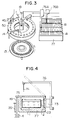
- FIG. 3 schematically illustrates an analyzing apparatus.
- Fig. 4 illustrates a reagent container housing unit of the analyzing apparatus.
- a reagent container housing unit 77 disposed in the reagent container accommodating portion is made fixed such that it does not move the first reagent containers 1A and the second reagent containers 1B.
- Reagent pipetting mechanisms 76A and 76B for the corresponding reagent systems can be stopped in such a manner that they can face each of the containers and can be moved over the reagent container rows.
- the reagent selectively picked from the containers 1A and 1B is delivered to the reaction container on the reaction disk 50 by a pipette probe 74.
- the housing unit 77 has a light transmission window 23.
- a bar code reader 73 reads through the window 23 the data on the reagent which is printed on a bar code label 2 adhered to each of the reagent containers 1.
- the bar code reader 73 is mounted on a movable member of the reagent pipetting mechanism 76. To read the bar code, the movable member is moved in the lateral direction, i.e., along the row of the containers, so that the bar codes on all the reagent containers can be read.
- a lid 75 is provided on the housing unit 77 in such a manner that it can be opened and closed. When the reagent containers are placed in or removed from the housing unit 77, the lid 75 is opened. After the reagent containers have been placed, the lid 75 is closed. When closing of the lid 75 is detected by the opening/closing detector 4, the reading operation of the bar code reader 73 begins.
- the operator can reliably grasp the data on the liquid contained in each of the containers by closing the lid of the container housing unit after he/she has placed the containers therein.
- newest data can be obtained without errors even when the containers in the container housing unit are replaced.
- the analyzing apparatus automatically makes collation, a trouble caused by inadequate reagent placed on the incorrect reagent position can be prevented.
Landscapes
- Engineering & Computer Science (AREA)
- Physics & Mathematics (AREA)
- General Physics & Mathematics (AREA)
- Health & Medical Sciences (AREA)
- General Health & Medical Sciences (AREA)
- Analytical Chemistry (AREA)
- Electromagnetism (AREA)
- Computer Vision & Pattern Recognition (AREA)
- Quality & Reliability (AREA)
- Theoretical Computer Science (AREA)
- Life Sciences & Earth Sciences (AREA)
- Chemical & Material Sciences (AREA)
- Artificial Intelligence (AREA)
- Biochemistry (AREA)
- Immunology (AREA)
- Pathology (AREA)
- Toxicology (AREA)
- Automatic Analysis And Handling Materials Therefor (AREA)
- Sampling And Sample Adjustment (AREA)
Applications Claiming Priority (2)
| Application Number | Priority Date | Filing Date | Title |
|---|---|---|---|
| JP3096721A JP2692413B2 (ja) | 1991-04-26 | 1991-04-26 | 自動分析装置およびそれに用いる試薬取扱方法 |
| JP96721/91 | 1991-04-26 |
Publications (3)
| Publication Number | Publication Date |
|---|---|
| EP0510686A2 true EP0510686A2 (fr) | 1992-10-28 |
| EP0510686A3 EP0510686A3 (en) | 1993-02-24 |
| EP0510686B1 EP0510686B1 (fr) | 1997-07-09 |
Family
ID=14172604
Family Applications (1)
| Application Number | Title | Priority Date | Filing Date |
|---|---|---|---|
| EP92107052A Expired - Lifetime EP0510686B1 (fr) | 1991-04-26 | 1992-04-24 | Automate d'analyse lisant les données associées aux récipients et méthode de manipulation des réactifs dans cet automate |
Country Status (3)
| Country | Link |
|---|---|
| EP (1) | EP0510686B1 (fr) |
| JP (1) | JP2692413B2 (fr) |
| DE (1) | DE69220714T2 (fr) |
Cited By (23)
| Publication number | Priority date | Publication date | Assignee | Title |
|---|---|---|---|---|
| WO1994002857A1 (fr) * | 1992-07-16 | 1994-02-03 | Schiapparelli Biosystems, Inc. | Systeme de controle de reactif et d'identification de flacons de reactif pour appareil d'analyse chimique |
| EP0678747A1 (fr) * | 1994-04-21 | 1995-10-25 | Kone Oy | Système de stockage de réactifs et récipient à réactifs |
| EP0731355A3 (fr) * | 1995-03-08 | 1998-04-01 | Hitachi, Ltd. | Méthode de manutention de réactifs, et appareil pour éviter leur perte d'activité |
| EP0845674A1 (fr) * | 1996-11-15 | 1998-06-03 | Hitachi, Ltd. | Procédé et appareil pour l'analyse automatique des solutions d'échantillons |
| EP0753745A3 (fr) * | 1995-07-11 | 1998-08-19 | Hitachi, Ltd. | Méthode et dispositif de gestion de réactifs |
| EP0762125A3 (fr) * | 1995-09-05 | 1998-08-26 | Hitachi, Ltd. | Procédé d'analyse automatique utilisant une pluralité de réactifs et dispositif pour sa mise en oeuvre |
| WO1999067140A1 (fr) * | 1998-06-08 | 1999-12-29 | Arom Pak Ab | Systeme, procede et dispositif doseur permettant de distribuer de faibles doses |
| WO2003045560A3 (fr) * | 2001-11-26 | 2004-03-18 | Lab Vision Corp | Systeme automatise de coloration de tissus et recipient de reactif |
| EP1422528A3 (fr) * | 2002-11-21 | 2004-08-04 | Hitachi High-Technologies Corporation | Analyseur automatique |
| EP1477816A3 (fr) * | 2003-05-14 | 2005-02-02 | Hitachi High-Technologies Corporation | Analyseur automatique |
| US6998270B2 (en) | 2001-11-26 | 2006-02-14 | Lab Vision Corporation | Automated tissue staining system and reagent container |
| EP1767949A1 (fr) * | 2005-09-21 | 2007-03-28 | F.Hoffmann-La Roche Ag | Ensemble de récipients a réactifs et analyseur comprenant cet ensemble |
| US7732212B1 (en) * | 2000-03-03 | 2010-06-08 | Hitachi, Ltd. | Method of management of analytical data and system for management of analytical data |
| EP1355160A4 (fr) * | 2001-01-23 | 2010-08-04 | Hitachi Ltd | Analyseur automatique |
| EP2458389A1 (fr) * | 2010-11-24 | 2012-05-30 | F. Hoffmann-La Roche AG | Détection de positionnement incorrect de récipients de liquide |
| US8920722B2 (en) | 2006-06-30 | 2014-12-30 | Sysmex Corporation | Sample analyzer and sample analyzing method |
| EP2853900A1 (fr) * | 2013-09-27 | 2015-04-01 | Sysmex Corporation | Analyseur et procédé d'analyse au moyen d'un récipient de pointe avec couvercle |
| US9248451B2 (en) | 2008-10-27 | 2016-02-02 | Sysmex Corporation | Sample analyzer comprising a reagent container holder |
| EP2400306A3 (fr) * | 2010-06-24 | 2017-11-01 | Sysmex Corporation | Analyseur d'échantillons et procédé d'aspiration de liquide |
| EP2372368A3 (fr) * | 2010-03-30 | 2017-11-22 | Sysmex Corporation | Analyseur d'échantillons et procédé de notification de l'utilisateur avec celui-ci |
| US9952237B2 (en) | 2011-01-28 | 2018-04-24 | Quanterix Corporation | Systems, devices, and methods for ultra-sensitive detection of molecules or particles |
| US10401209B2 (en) | 2016-06-22 | 2019-09-03 | Abbott Laboratories | Liquid level sensing apparatus and related methods |
| EP3693744A1 (fr) * | 2010-11-17 | 2020-08-12 | Hitachi High-Tech Corporation | Analyseur automatique |
Families Citing this family (23)
| Publication number | Priority date | Publication date | Assignee | Title |
|---|---|---|---|---|
| JP3255001B2 (ja) * | 1995-03-08 | 2002-02-12 | 株式会社日立製作所 | 試薬の効力低下を抑制するための試薬取扱方法およびその装置 |
| JP3533258B2 (ja) * | 1995-03-31 | 2004-05-31 | 株式会社東芝 | 化学分析装置用試薬システム |
| JP3314629B2 (ja) * | 1996-09-24 | 2002-08-12 | 株式会社日立製作所 | 自動分析装置 |
| JP2002048800A (ja) * | 2000-07-31 | 2002-02-15 | Olympus Optical Co Ltd | 自動分析装置 |
| JP4795580B2 (ja) * | 2001-08-30 | 2011-10-19 | シスメックス株式会社 | 試薬管理方法および分析装置 |
| JP4160364B2 (ja) * | 2002-11-06 | 2008-10-01 | オリンパス株式会社 | 試薬容器および自動分析装置 |
| JP4130905B2 (ja) * | 2003-06-23 | 2008-08-13 | 株式会社日立ハイテクノロジーズ | 自動分析装置 |
| JP3808895B2 (ja) * | 2005-12-26 | 2006-08-16 | 東芝メディカルシステムズ株式会社 | 自動分析装置 |
| JP2007333466A (ja) * | 2006-06-13 | 2007-12-27 | Olympus Corp | 分析装置 |
| JP5009684B2 (ja) * | 2006-06-30 | 2012-08-22 | シスメックス株式会社 | 試料分析装置 |
| JP2009031175A (ja) * | 2007-07-30 | 2009-02-12 | Hitachi High-Technologies Corp | 自動分析装置 |
| JP5167019B2 (ja) * | 2008-07-31 | 2013-03-21 | ベックマン コールター, インコーポレイテッド | 自動分析装置及びその試薬分注方法 |
| JP5127637B2 (ja) * | 2008-08-29 | 2013-01-23 | 株式会社東芝 | 自動分析装置 |
| US9691114B2 (en) | 2008-10-23 | 2017-06-27 | Whirlpool Corporation | Consumables inventory management method |
| US20100106515A1 (en) | 2008-10-23 | 2010-04-29 | Whirlpool Corporation | Introduction and activation of a self-reporting portable container into an inventory system |
| US7933733B2 (en) | 2008-10-23 | 2011-04-26 | Whirlpool Corporation | Attribute sensing processes |
| US8477029B2 (en) | 2008-10-23 | 2013-07-02 | Whirlpool Corporation | Modular attribute sensing device |
| JP5160651B2 (ja) * | 2008-11-21 | 2013-03-13 | 株式会社日立ハイテクノロジーズ | 自動分析装置 |
| JP5466066B2 (ja) * | 2010-03-30 | 2014-04-09 | シスメックス株式会社 | 検体分析装置 |
| JP5178891B2 (ja) * | 2011-08-23 | 2013-04-10 | 株式会社日立ハイテクノロジーズ | 自動分析装置 |
| CN109690321B (zh) * | 2016-09-16 | 2022-11-15 | 株式会社日立高新技术 | 自动分析装置、自动分析系统以及试剂清单的显示方法 |
| JP7123548B2 (ja) * | 2017-11-21 | 2022-08-23 | キヤノンメディカルシステムズ株式会社 | 自動分析装置 |
| EP3779468B1 (fr) * | 2018-04-12 | 2023-08-16 | Hitachi High-Tech Corporation | Dispositif d'analyse d'électrolyte |
Family Cites Families (11)
| Publication number | Priority date | Publication date | Assignee | Title |
|---|---|---|---|---|
| JPS5782769A (en) * | 1980-11-10 | 1982-05-24 | Hitachi Ltd | Automatic analyzing device |
| JPS621674Y2 (fr) * | 1981-02-10 | 1987-01-14 | ||
| JPH0124628Y2 (fr) * | 1981-05-21 | 1989-07-25 | ||
| JPH0664070B2 (ja) * | 1983-06-07 | 1994-08-22 | 日本テクトロン株式会社 | 試薬判別分注方法及びその装置 |
| US4647432A (en) * | 1982-11-30 | 1987-03-03 | Japan Tectron Instruments Corporation Tokuyama Soda Kabushiki Kaisha | Automatic analysis apparatus |
| JPS6017362A (ja) * | 1983-07-11 | 1985-01-29 | Nippon Tectron Co Ltd | 自動分析装置 |
| JPS6064254A (ja) * | 1983-09-19 | 1985-04-12 | Mitsubishi Chem Ind Ltd | 自動分析装置 |
| US4764342A (en) * | 1985-02-27 | 1988-08-16 | Fisher Scientific Company | Reagent handling |
| JPS6321139A (ja) * | 1986-07-16 | 1988-01-28 | 新日本製鐵株式会社 | 脱酸素能を有する低クロムメツキ鋼板製密閉容器 |
| GB2216259A (en) * | 1988-03-31 | 1989-10-04 | Microvol Ltd | Dispenser for chemical analysis carrying a code |
| JP2595063B2 (ja) * | 1988-09-16 | 1997-03-26 | 株式会社日立製作所 | 自動分析装置 |
-
1991
- 1991-04-26 JP JP3096721A patent/JP2692413B2/ja not_active Expired - Lifetime
-
1992
- 1992-04-24 DE DE1992620714 patent/DE69220714T2/de not_active Expired - Lifetime
- 1992-04-24 EP EP92107052A patent/EP0510686B1/fr not_active Expired - Lifetime
Cited By (43)
| Publication number | Priority date | Publication date | Assignee | Title |
|---|---|---|---|---|
| WO1994002857A1 (fr) * | 1992-07-16 | 1994-02-03 | Schiapparelli Biosystems, Inc. | Systeme de controle de reactif et d'identification de flacons de reactif pour appareil d'analyse chimique |
| EP0678747A1 (fr) * | 1994-04-21 | 1995-10-25 | Kone Oy | Système de stockage de réactifs et récipient à réactifs |
| EP0731355A3 (fr) * | 1995-03-08 | 1998-04-01 | Hitachi, Ltd. | Méthode de manutention de réactifs, et appareil pour éviter leur perte d'activité |
| CN1120371C (zh) * | 1995-07-11 | 2003-09-03 | 株式会社日立制作所 | 试剂管理方法和装置 |
| EP0753745A3 (fr) * | 1995-07-11 | 1998-08-19 | Hitachi, Ltd. | Méthode et dispositif de gestion de réactifs |
| EP0762125A3 (fr) * | 1995-09-05 | 1998-08-26 | Hitachi, Ltd. | Procédé d'analyse automatique utilisant une pluralité de réactifs et dispositif pour sa mise en oeuvre |
| EP0845674A1 (fr) * | 1996-11-15 | 1998-06-03 | Hitachi, Ltd. | Procédé et appareil pour l'analyse automatique des solutions d'échantillons |
| US6090630A (en) * | 1996-11-15 | 2000-07-18 | Hitachi, Ltd. | Method and apparatus for automatically analyzing reaction solutions of samples |
| WO1999067140A1 (fr) * | 1998-06-08 | 1999-12-29 | Arom Pak Ab | Systeme, procede et dispositif doseur permettant de distribuer de faibles doses |
| US7732212B1 (en) * | 2000-03-03 | 2010-06-08 | Hitachi, Ltd. | Method of management of analytical data and system for management of analytical data |
| EP1355160A4 (fr) * | 2001-01-23 | 2010-08-04 | Hitachi Ltd | Analyseur automatique |
| WO2003045560A3 (fr) * | 2001-11-26 | 2004-03-18 | Lab Vision Corp | Systeme automatise de coloration de tissus et recipient de reactif |
| US8585987B2 (en) | 2001-11-26 | 2013-11-19 | Lab Vision Corporation | Automated tissue staining system and reagent container |
| US6998270B2 (en) | 2001-11-26 | 2006-02-14 | Lab Vision Corporation | Automated tissue staining system and reagent container |
| US8142739B2 (en) | 2001-11-26 | 2012-03-27 | Lab Vision Corporation | Automated tissue staining system and reagent container |
| US7901941B2 (en) | 2001-11-26 | 2011-03-08 | Lab Vision Corporation | Automated tissue staining system and reagent container |
| US7435383B2 (en) | 2001-11-26 | 2008-10-14 | Lab Vision Corporation | Automated tissue staining system and reagent container |
| US7642093B2 (en) | 2001-11-26 | 2010-01-05 | Lab Vision Corporation | Automated tissue staining system and reagent container |
| EP1422528A3 (fr) * | 2002-11-21 | 2004-08-04 | Hitachi High-Technologies Corporation | Analyseur automatique |
| US9513302B2 (en) | 2003-05-14 | 2016-12-06 | Hitachi High-Technologies Corporation | Reagent transfer device |
| CN100347550C (zh) * | 2003-05-14 | 2007-11-07 | 株式会社日立高新技术 | 自动分析装置 |
| US8158058B2 (en) | 2003-05-14 | 2012-04-17 | Hitachi High-Technologies Corporation | Automatic analyzer |
| US10605817B2 (en) | 2003-05-14 | 2020-03-31 | Hitachi High-Technologies Corporation | Automatic analyzer |
| EP1477816A3 (fr) * | 2003-05-14 | 2005-02-02 | Hitachi High-Technologies Corporation | Analyseur automatique |
| US10151766B2 (en) | 2003-05-14 | 2018-12-11 | Hitachi High-Technologies Corporation | Automatic analyzer |
| EP1767949A1 (fr) * | 2005-09-21 | 2007-03-28 | F.Hoffmann-La Roche Ag | Ensemble de récipients a réactifs et analyseur comprenant cet ensemble |
| US7731898B2 (en) | 2005-09-21 | 2010-06-08 | Roche Diagnostics Operations, Inc. | Reagent container assembly and analyzer comprising such assembly |
| US8920722B2 (en) | 2006-06-30 | 2014-12-30 | Sysmex Corporation | Sample analyzer and sample analyzing method |
| US9248451B2 (en) | 2008-10-27 | 2016-02-02 | Sysmex Corporation | Sample analyzer comprising a reagent container holder |
| EP2372368A3 (fr) * | 2010-03-30 | 2017-11-22 | Sysmex Corporation | Analyseur d'échantillons et procédé de notification de l'utilisateur avec celui-ci |
| EP2400306A3 (fr) * | 2010-06-24 | 2017-11-01 | Sysmex Corporation | Analyseur d'échantillons et procédé d'aspiration de liquide |
| US10908175B2 (en) | 2010-06-24 | 2021-02-02 | Sysmex Corporation | Sample analyzer and liquid aspirating method |
| EP3693744A1 (fr) * | 2010-11-17 | 2020-08-12 | Hitachi High-Tech Corporation | Analyseur automatique |
| EP2458389A1 (fr) * | 2010-11-24 | 2012-05-30 | F. Hoffmann-La Roche AG | Détection de positionnement incorrect de récipients de liquide |
| US9952237B2 (en) | 2011-01-28 | 2018-04-24 | Quanterix Corporation | Systems, devices, and methods for ultra-sensitive detection of molecules or particles |
| US11112415B2 (en) | 2011-01-28 | 2021-09-07 | Quanterix Corporation | Systems, devices, and methods for ultra-sensitive detection of molecules or particles |
| EP2668509B1 (fr) * | 2011-01-28 | 2022-09-07 | Quanterix Corporation | Dispositifs de détection ultrasensible de molécules ou de particules |
| US11977087B2 (en) | 2011-01-28 | 2024-05-07 | Quanterix Corporation | Systems, devices, and methods for ultra-sensitive detection of molecules or particles |
| EP2853900A1 (fr) * | 2013-09-27 | 2015-04-01 | Sysmex Corporation | Analyseur et procédé d'analyse au moyen d'un récipient de pointe avec couvercle |
| CN104515865B (zh) * | 2013-09-27 | 2018-08-07 | 希森美康株式会社 | 分析装置、分析方法及吸头收纳容器 |
| CN104515865A (zh) * | 2013-09-27 | 2015-04-15 | 希森美康株式会社 | 分析装置、分析方法及吸头收纳容器 |
| US10401209B2 (en) | 2016-06-22 | 2019-09-03 | Abbott Laboratories | Liquid level sensing apparatus and related methods |
| US10760939B2 (en) | 2016-06-22 | 2020-09-01 | Abbott Laboratories | Liquid level sensing apparatus and related methods |
Also Published As
| Publication number | Publication date |
|---|---|
| EP0510686A3 (en) | 1993-02-24 |
| DE69220714D1 (de) | 1997-08-14 |
| JPH04326063A (ja) | 1992-11-16 |
| JP2692413B2 (ja) | 1997-12-17 |
| DE69220714T2 (de) | 1997-11-06 |
| EP0510686B1 (fr) | 1997-07-09 |
Similar Documents
| Publication | Publication Date | Title |
|---|---|---|
| EP0510686B1 (fr) | Automate d'analyse lisant les données associées aux récipients et méthode de manipulation des réactifs dans cet automate | |
| US7185288B2 (en) | Operator interface module segmented by function in an automatic clinical analyzer | |
| JP3990944B2 (ja) | 自動分析装置 | |
| EP0952452B1 (fr) | Appareil d'analyses automatisé avec fonction réglable d'opération restrictive | |
| EP2040081B1 (fr) | Analyseur d'échantillon et procédé d'affichage des informations d'erreur | |
| US4873633A (en) | User controlled off-center light absorbance reading adjuster in a liquid handling and reaction system | |
| EP0651884B1 (fr) | Systeme de controle de reactif et d'identification de flacons de reactif pour appareil d'analyse chimique | |
| JP2525063B2 (ja) | 自動分析方法 | |
| US7771656B2 (en) | Automatic analyzer | |
| EP0871034B1 (fr) | Appareil d'analyses automatisé | |
| US6579717B1 (en) | Specific solution handling method for calibration and quality control by automatic analytical apparatus | |
| EP1826572B1 (fr) | Analyseur avec verification de programmation | |
| JP4081146B2 (ja) | 分析システム | |
| US6409968B1 (en) | Automatic analysis apparatus for biological fluid sample and automatic analysis method therefor | |
| EP2068153A2 (fr) | Analyseur automatique | |
| JPH10142230A (ja) | 自動分析装置 | |
| EP0409606B1 (fr) | Analyseur automatique d'essais immunologiques | |
| JP3500295B2 (ja) | 検体処理システム | |
| JP3849343B2 (ja) | 自動分析装置 | |
| JP3029330B2 (ja) | 自動化学分析装置 | |
| EP0569215A2 (fr) | Appareil d'analyse chimique clinique | |
| JPH0666813A (ja) | 自動分析装置 | |
| CN109298194B (zh) | 自动分析装置 | |
| EP1037708B1 (fr) | Poste de chargement pour systeme robotique | |
| JP4434180B2 (ja) | 自動分析装置 |
Legal Events
| Date | Code | Title | Description |
|---|---|---|---|
| PUAI | Public reference made under article 153(3) epc to a published international application that has entered the european phase |
Free format text: ORIGINAL CODE: 0009012 |
|
| 17P | Request for examination filed |
Effective date: 19920424 |
|
| AK | Designated contracting states |
Kind code of ref document: A2 Designated state(s): DE FR GB |
|
| PUAL | Search report despatched |
Free format text: ORIGINAL CODE: 0009013 |
|
| AK | Designated contracting states |
Kind code of ref document: A3 Designated state(s): DE FR GB |
|
| 17Q | First examination report despatched |
Effective date: 19940425 |
|
| GRAG | Despatch of communication of intention to grant |
Free format text: ORIGINAL CODE: EPIDOS AGRA |
|
| GRAH | Despatch of communication of intention to grant a patent |
Free format text: ORIGINAL CODE: EPIDOS IGRA |
|
| GRAH | Despatch of communication of intention to grant a patent |
Free format text: ORIGINAL CODE: EPIDOS IGRA |
|
| GRAA | (expected) grant |
Free format text: ORIGINAL CODE: 0009210 |
|
| AK | Designated contracting states |
Kind code of ref document: B1 Designated state(s): DE FR GB |
|
| ET | Fr: translation filed | ||
| REF | Corresponds to: |
Ref document number: 69220714 Country of ref document: DE Date of ref document: 19970814 |
|
| PLBE | No opposition filed within time limit |
Free format text: ORIGINAL CODE: 0009261 |
|
| STAA | Information on the status of an ep patent application or granted ep patent |
Free format text: STATUS: NO OPPOSITION FILED WITHIN TIME LIMIT |
|
| 26N | No opposition filed | ||
| REG | Reference to a national code |
Ref country code: GB Ref legal event code: IF02 |
|
| PGFP | Annual fee paid to national office [announced via postgrant information from national office to epo] |
Ref country code: GB Payment date: 20060424 Year of fee payment: 15 |
|
| GBPC | Gb: european patent ceased through non-payment of renewal fee |
Effective date: 20070424 |
|
| PG25 | Lapsed in a contracting state [announced via postgrant information from national office to epo] |
Ref country code: GB Free format text: LAPSE BECAUSE OF NON-PAYMENT OF DUE FEES Effective date: 20070424 |
|
| PGFP | Annual fee paid to national office [announced via postgrant information from national office to epo] |
Ref country code: DE Payment date: 20110420 Year of fee payment: 20 Ref country code: FR Payment date: 20110426 Year of fee payment: 20 |
|
| REG | Reference to a national code |
Ref country code: DE Ref legal event code: R071 Ref document number: 69220714 Country of ref document: DE |
|
| REG | Reference to a national code |
Ref country code: DE Ref legal event code: R071 Ref document number: 69220714 Country of ref document: DE |
|
| PG25 | Lapsed in a contracting state [announced via postgrant information from national office to epo] |
Ref country code: DE Free format text: LAPSE BECAUSE OF EXPIRATION OF PROTECTION Effective date: 20120425 |