EP0517263A2 - Appareil de formation d'image par transfert thermique - Google Patents
Appareil de formation d'image par transfert thermique Download PDFInfo
- Publication number
- EP0517263A2 EP0517263A2 EP92109575A EP92109575A EP0517263A2 EP 0517263 A2 EP0517263 A2 EP 0517263A2 EP 92109575 A EP92109575 A EP 92109575A EP 92109575 A EP92109575 A EP 92109575A EP 0517263 A2 EP0517263 A2 EP 0517263A2
- Authority
- EP
- European Patent Office
- Prior art keywords
- density
- pixel data
- conversion
- dots
- gamma characteristic
- Prior art date
- Legal status (The legal status is an assumption and is not a legal conclusion. Google has not performed a legal analysis and makes no representation as to the accuracy of the status listed.)
- Granted
Links
- 238000012546 transfer Methods 0.000 title claims abstract description 30
- 238000006243 chemical reaction Methods 0.000 claims abstract description 304
- 230000006870 function Effects 0.000 claims abstract description 274
- 238000005070 sampling Methods 0.000 claims abstract description 58
- 238000010438 heat treatment Methods 0.000 claims abstract description 44
- 239000011159 matrix material Substances 0.000 claims abstract description 18
- 230000008859 change Effects 0.000 claims description 9
- 239000000758 substrate Substances 0.000 claims description 9
- 230000007613 environmental effect Effects 0.000 claims description 2
- 230000007246 mechanism Effects 0.000 abstract description 4
- 238000007639 printing Methods 0.000 description 45
- 238000000034 method Methods 0.000 description 10
- 238000012937 correction Methods 0.000 description 9
- 238000000926 separation method Methods 0.000 description 5
- 239000003086 colorant Substances 0.000 description 4
- 238000013500 data storage Methods 0.000 description 4
- 230000007423 decrease Effects 0.000 description 3
- 238000010586 diagram Methods 0.000 description 3
- 230000003247 decreasing effect Effects 0.000 description 2
- 238000006073 displacement reaction Methods 0.000 description 2
- 238000012545 processing Methods 0.000 description 2
- 238000010023 transfer printing Methods 0.000 description 2
- 238000013459 approach Methods 0.000 description 1
- 230000008901 benefit Effects 0.000 description 1
- 230000015572 biosynthetic process Effects 0.000 description 1
- 239000000470 constituent Substances 0.000 description 1
- 230000001419 dependent effect Effects 0.000 description 1
- 238000007646 gravure printing Methods 0.000 description 1
- 230000006872 improvement Effects 0.000 description 1
- 238000002844 melting Methods 0.000 description 1
- 230000008018 melting Effects 0.000 description 1
- 239000000049 pigment Substances 0.000 description 1
- 230000008569 process Effects 0.000 description 1
- 239000007787 solid Substances 0.000 description 1
Images


Classifications
-
- H—ELECTRICITY
- H04—ELECTRIC COMMUNICATION TECHNIQUE
- H04N—PICTORIAL COMMUNICATION, e.g. TELEVISION
- H04N1/00—Scanning, transmission or reproduction of documents or the like, e.g. facsimile transmission; Details thereof
- H04N1/46—Colour picture communication systems
- H04N1/52—Circuits or arrangements for halftone screening
-
- H—ELECTRICITY
- H04—ELECTRIC COMMUNICATION TECHNIQUE
- H04N—PICTORIAL COMMUNICATION, e.g. TELEVISION
- H04N1/00—Scanning, transmission or reproduction of documents or the like, e.g. facsimile transmission; Details thereof
- H04N1/40—Picture signal circuits
- H04N1/405—Halftoning, i.e. converting the picture signal of a continuous-tone original into a corresponding signal showing only two levels
- H04N1/4055—Halftoning, i.e. converting the picture signal of a continuous-tone original into a corresponding signal showing only two levels producing a clustered dots or a size modulated halftone pattern
- H04N1/4058—Halftoning, i.e. converting the picture signal of a continuous-tone original into a corresponding signal showing only two levels producing a clustered dots or a size modulated halftone pattern with details for producing a halftone screen at an oblique angle
Definitions
- the present invention relates to an image forming apparatus.
- a thermal transfer printer has a recording head provided with small heating resistor elements integrated on a substrate and uses an ink sheet or ribbon formed of macromolecular film coated with wax containing pigment so that the printer forms dots on recording paper by melting ink in a small area of the ink sheet or ribbon through supply of signals based on pixel data to the heating resistor elements selectively.
- Such a thermal transfer image forming apparatus has been used widely in the field of full-color printing requiring high- density dot forming, because heating resistor elements as dot forming elements can be arranged in a small size.
- the improvement of the gradient and the setting of the screen angle can be provided simultaneously.
- the proposed printing system requires a large quantity of matrix data if the gradient is made higher. There arises therefore a problem in that the capacity of a memory for storing the large quantity of matrix data therein increases.
- the invention provides an image forming apparatus in which a plurality of heating resistor elements are arranged in a line on a surface of a substrate, and the heating resistor elements are made to generate heat selectively in accordance with pixel data so as to melt ink of an ink sheet or an ink ribbon to thereby form dots on recording paper, and more particularly, to a technique for controlling the gradation and color reproduction in such an image forming apparatus.
- a first aspect of the present invention is to provide a thermal transfer image forming apparatus, in which the thermal interference between heating resistor elements constituting a dot forming means is made small as sufficiently as possible so that gradation is expressed by the area of each dot per se to thereby improve the gradation property and the resolution, and, on the other hand, the form of application of gamma conversion characteristics is changed to thereby change, for every primary color, the positions where main dots corresponding to at least 2 x 2 pixels are formed, whereby both generation of net-like noise and color cloud due to displacement in dot forming position can be prevented to make the printing quality excellent.
- a second aspect of the invention is to provide a novel thermal transfer image forming apparatus in which even in the case where the quantity of data for setting the screen angle is small, a screen angle can be set while both the gradient and resolution are kept.
- a third aspect of the invention is to provide a novel thermal transfer image forming apparatus in which the density change of each dot with the temperature change of the recording head substrate can be prevented by a simple circuit configuration.
- the present invention provides a thermal transfer image forming apparatus which comprises: a recording head having a plurality of heating resistor elements arranged in a line; means for carrying a sheet of recording paper and an ink sheet at a predetermined pitch; an image data reading means for continuously reading N-lines' pixel data (N being an integer of N ⁇ 2) constituting input image data; a sampling means for sampling the N-lines' pixel data into a matrix of N x N pixels; a gamma conversion means having a first gamma characteristic conversion function for outputting print data to form main dots by performing gamma conversion proportionally in a density range of from a low density to a high density, a second gamma characteristic conversion function for outputting print data being lower in density than the first gamma characteristic conversion function to form subsidiary dots, and third and fourth gamma characteristic conversion functions to form no dot in a large part of the density range, thereby expressing the pixel density as a dot size for each of the N x
- the thermal transfer printing mechanism comprises a paper supply mechanism 4 for pulling a sheet of recording paper 1 out of a stacker 2, which stocks sheets of recording paper 1, through a pickup roller 3 to convey the recording paper 1 to a print region, a platen 5 for conveying the recording paper 1 and an ink sheet 9 at a predetermined speed, a thermal transfer recording head 6 which is brought into forced contact with the platen 5 at the time of printing, a conveyance roller 8 for returning the recording paper 1 to the stacker 2 after printing, a stock roller 10 for feeding the ink ribbon 9, and a takeup roller 11. Further, a circuit substrate 12 having a control circuit incorporated therein, which will be described later, is put in the lower portion of a box.
- the thermal transfer recording head 6 includes a substrate 13, an array of heating resistor elements 14, arranged in a line at intervals of a predetermined pitch on a surface of the substrate 13, and lead wires 15 and 16 led out in a direction of feeding of paper.
- the reference numeral 17 designates a microcomputer constituting a main portion of the controller.
- the microcomputer 17 comprises a CPU 18, an ROM 19 for storing control programs, data processing programs which will be described later and gamma characteristic conversion functions, and an RAM 20 serving as a data processing buffer and also as a frame memory.
- the microcomputer 17 is connected, through interfaces 21 and 22, to an external device such as a personal computer or the like, a recording head drive circuit 23, and a motor drive circuit 24.
- the recording head drive circuit 23 is arranged so that electric energy corresponding to density data outputted from the interface 22 is supplied to each of the heating resistor elements 14 of the thermal transfer recording head 6.
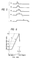
- the recording head drive circuit 23 is arranged so that pulse-like electric power successively increasing in time T1, T2, T3, T4, Vietnamese Tn correspondingly to the density B1, B2, B3, B4, Vietnamese Bn is supplied to each of the heating resistor elements 14 of the thermal transfer recording head 6.
- the motor drive circuit 24 is provided to drive a motor 25 connected to the pickup roller 3, the platen 5 and the conveyance roller 8, and the motor drive circuit 24 is arranged to output a drive pulse to give the motor 25 a rotation direction and a rotation speed in accordance with an instruction outputted from the interface 22.
- the reference numeral 30 designates an image memory for storing image data outputted from the external device.
- the image memory 30 stores a predetermined quantity of image data (for example, one-page's image data for each color) outputted from the external device.
- the reference numeral 31 designates an image data reading means for extracting N-lines' pixel data (N being an integer of N ⁇ 2) from the image data stored in the image memory 30 while shifting the image data by N lines (in this embodiment, by 2 lines), to supply the N-lines' image data to a line buffer 32.
- the reference numeral 33 designates a sampling means for sampling N columns (N is an integer of N ⁇ 2) in a main scanning direction from the image data stored in the line buffer 32, that is, for sampling N x N pixels (in this embodiment, 2 x 2 pixels), to supply the sampled data to a gamma conversion means 34.
- the gamma conversion means 34 is arranged to store data for defining the relationship between the density of pixel data and the conversion print data to designate the density of dot at the time of printing (hereinafter referred to as "conversion print data") correspondingly to the density of pixel data as shown in Fig. 6 to thereby function as a filter or a print density setting means for the pixel data given from the sampling means.
- gamma characteristic conversion functions set in the gamma conversion means 34 A plurality of characteristics (in this embodiment, four kinds of gamma characteristic conversion functions) are stored in the gamma conversion means 34.
- a gamma characteristic conversion function ⁇ 1 has a characteristic in which: conversion print data Da for supplying minimum energy to keep the temperature of a heating resistor element constant regardless of the environment is set, in the case where the density of pixel data is zero, to form no transfer dot; the density of conversion print data is increased from Da to a maximum density Db proportionally to the density of pixel data in an intermediate density region thereof; the conversion print data Db is kept constant in a range of from the intermediate density region to a high density region; and the density of conversion print,data is decreased to a density Dc near the density of image data in the maximum density of pixel data.
- the density De is set to a dot density value of 11.8 dot/mm in the case of binary printing such as character printing. That is, the density De is generally set to a value for supplying energy of about 0.125 mJ/dot to a heating resistor element.
- the density Db is set to a value for supplying energy about twice as much as the energy of the density De.
- the density Dc is set to a value slightly higher than the value of De.
- the density Dd is set to a value slightly lower than the value of De.
- a gamma characteristic conversion function ⁇ 2 has a characteristic in which the density Dd near the density of pixel data is generated only in the vicinity of the maximum density value of pixel data.
- a gamma characteristic conversion function ⁇ 3 has a characteristic in which the density Dd is generated only in the vicinity of the maximum density value of pixel data in the same manner as the gamma characteristic conversion function ⁇ 2.
- a gamma characteristic conversion function ⁇ 4 has a characteristic in which: the conversion print data D n for forming a minimum size dot stably is kept constant in the low density region of pixel data; the density of conversion print data is in creased substantially linearly from Da to a maximum conversion print data Db proportionally to the density of pixel data in a range of from the intermediate density region to the high density region; and the density of conversion print data is decreased to the density Dc near the density of image data in the maximum density region of pixel data.
- gamma characteristics can be assigned to four pixels in the sampled matrix data so that the sampling area can be expressed not only through generation of a main dot as a center of image expression and a subsidiary dot adjacent to the main dot on the basis of the conversion characteristics ⁇ 1 and ⁇ 4 but through addition of dots respectively based on the conversion characteristics ⁇ 2 and ⁇ 3 thereto for the maximum density of pixel data.
- the reference numeral 35 designates a conversion characteristic selection means in which data for assigning the four gamma characteristic conversion functions ⁇ 1 to ⁇ 4 to sampled matrix image data D11, D12, ?? D14, D21, D22, . . D24, D31, D32, . D34, D41, D42, ?? D44 for every primary color given to the image memory 30.
- the reference numeral 36 designates a print buffer connected to the Medr conversion means.
- the heating resistor element 14 thus driven is free from thermal interference with the adjacent heating resistor elements 14′ and 14 ⁇ so that the areas of the adjacent heating resistor elements 14′ and 14 ⁇ can be used as a dot forming area.
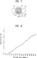
- the size of the resulting dot is proportional to relative input energy E supplied to the heating resistor element even in the case where the relative input energy E is separated into 32 stages as shown in Fig. 8.
- very high gradations can be expressed. Accordingly, dots having a density faithfully proportional to the density of pixel data can be formed. As a result, not only separate dots are formed in the intermediate density and in the high density but a solid image (Fig. 9(III)) is formed in the maximum density, when the energy increases as shown in Figs. 9(I) to 9(III).
- the pixel data D11 sampled by the sampling means 33 is converted into a conversion print data linearly proportional to the density thereof by the gamma characteristic conversion function ⁇ 1 of the gamma conversion means 34 selected by the conversion characteristic selection means 35.
- the pixel data D12 is converted into a conversion print data by the gamma characteristic conversion function ⁇ 2 so that dot forming energy is not applied except the case where the density Dd is given when the density takes its maximum value.
- the pixel data D21 is converted into a conversion print data so that dot forming energy is not applied except the case where the density Dd is given when the density of pixel data takes its maximum value.
- the pixel data D22 is converted into a conversion print data so that energy substantially sufficiently small to avoid dot forming is applied in the low density region and so that the convention print data is linearly proportional to the density of pixel data in the density region of not lower than the intermediate density region.
- the pixel data D21 and D22 in the same sampling area are printed. Because the functions ⁇ 3 and ⁇ 4 are respectively assigned to the pixel data D21 and D22, the pixel data D22 is printed but the pixel data D21 is not printed in the intermediate density region. Because adjacent heating resistor elements are in stoppage also in the printing of the second-line pixel data, the pixel data as a subject of printing is formed as a dot having a density faithful to the density subjected to conversion by the function ⁇ 4. Thereafter, printing is continued in the form as shown in Fig. 14, that is, by repeating the form of assignment of gamma characteristic conversion functions as shown in Fig. 13.
- the pixel data D11 and D22 are printed respectively as a main dot and as a subsidiary dot. Accordingly, the four pixel data D11 to D22 are expressed so that the main dot is supplemented with the subsidiary dot.
- Fig. 16 shows another form of conversion characteristics set by the conversion characteristic selection means 34.
- gamma characteristic conversion functions ⁇ 1, ⁇ 3, ⁇ 4 and ⁇ 2 are respectively assigned to four pixel data D11, D12, D21 and D22 sampled by the sampling means 33.
- a dot corresponding to the pixel data D11 is formed preferentially and a pixel after conversion of the pixel data D21 is formed as a subsidiary dot.
- Figs. 19(a) and 19(b) show other forms of conversion characteristics set by the conversion characteristic selection means 35.
- gamma characteristic conversion functions ⁇ 4, ⁇ 1, ⁇ 3 and ⁇ 2 are respectively assigned to four pixel data D11, D12, D21 and D22 as a first form (Fig. 19(a))
- gamma characteristic conversion functions ⁇ 3, ⁇ 2, ⁇ 4 and ⁇ 1 are respectively assigned to four pixel data D11, D12, D21 and D22 as a second form (Fig. 19(b)).
- first and second forms are used alternately as shown in Fig. 20.
- Figs. 22(a) and 22(b) show other forms of conversion characteristics set by the conversion characteristic selection means 35.
- gamma characteristic conversion functions ⁇ 1, ⁇ 2, ⁇ 3 and ⁇ 4 are respectively assigned to four pixel data D11, D12, D21 and D22 as a first form (Fig. 22(a))
- gamma characteristic conversion functions ⁇ 4, ⁇ 3, ⁇ 2 and ⁇ 1 are respectively assigned to four pixel data D11, D12, D21 and D22 as a second form (Fig. 22(b)).
- first and second forms are used alternately and in reverse order after two lines as shown in Fig. 23.
- the pixel data D11 are formed as main dots and the next pixel data D11 (pixel data D13 in the continuous form as shown in Fig. 23) adjacent thereto are formed as subsidiary dots at intervals of one dot from the main dots.
- the pixel data D22 are formed as main dots and the pixel data D22 are formed as subsidiary dots at intervals of one dot from the main dots so as to be prior to the main dots.
- Figs. 25(a) and 25(b) show other forms of conversion characteristics set by the conversion characteristic selection means 35.
- gamma characteristic conversion functions ⁇ 2, ⁇ 4, ⁇ 1 and ⁇ 3 are respectively assigned to four pixel data D11, D12, D21 and D22 as a first form (Fig. 25(a))
- gamma characteristic conversion functions ⁇ 3, ⁇ 1, ⁇ 4 and ⁇ 2 are respectively assigned to four pixel data D11, D12, D21 and D22 as a second form (Fig. 25(b)).
- first and second forms are used alternately and in reverse order after two lines as shown in Fig. 26.
- a dot based on the pixel data D21 is printed preferentially.
- the pixel data D12 is printed preferentially.
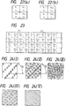
- dots at a screen angle of 135 degrees are formed in the low density region as shown in Fig. 27(I).
- dots based on the gamma characteristic conversion function ⁇ 4 as well as the dots based on the gamma characteristic conversion function ⁇ 1 are printed.
- the pixel data D12 are formed as main dots and the pixel data D12 (the pixel data D12 in the continuous form as shown in Fig.
- the pixel data D21 are formed as main dots and the pixel data D21 are printed as subsidiary dots at intervals of one dot from the main dots so as to be posterior to the main dots.
- blank portions are formed substantially circularly and separately so that ink for non-dot forming portions can be prevented from peeling wastefully. As a result, a gradation faithful to the density of pixel data can be expressed.
- Fig. 28 shows a second embodiment of the gamma characteristic conversion functions.
- the gamma characteristic conversion function ⁇ 1 has a characteristic in which: the conversion print data increases to the maximum density Db from a density to an extent that energy which is sufficient to keep the thermal condition of a heating resistor element constant in the same manner as the above-mentioned density Da but does not form any dot and which is slightly lower than that for the density Da in a range of from the low density region to the intermediate density region of the pixel data; the maximum density Db is then kept constant regardless of the density of pixel data; and then the conversion print data finally decreases to a density Dc in the vicinity of the maximum density of the pixel data.
- Each of the gamma characteristic conversion functions ⁇ 2 and ⁇ 3 is set so that a density Dg sufficiently small to form no dot is kept contact in the low density region of and the conversion print data then increases to a density Dd proportionally to the image density in a range of from the intermediate density region to the maximum density of pixel data. Further, the gamma characteristic conversion function ⁇ 4 is set so that the density Dd is given only in the maximum density of pixel data.
- dots based on the pixel data D11 are formed in the case where the density of pixel data in the sampling area is low.
- dots are formed like checkers as shown in Fig. 29(I), so that screen angles of 0 and 90 degrees are set.
- dots based on the gamma characteristic conversion functions ⁇ 2 and ⁇ 3 are formed as shown in Fig. 29(III).
- positions where main dots are formed are changed by the change of the form of application of the gamma characteristic conversion functions. Accordingly, sharp color printing can be performed by use of the advantage of screen angle setting in gravure printing or the like through setting of different application forms to three primary colors to express a color corresponding to pixel data.
- the gamma characteristic conversion functions in Fig. 6 are set so that the function ⁇ 1 decreases to the density Dc in the maximum density of pixel data and each of the functions ⁇ 2 and ⁇ 3 takes the density Dd in the maximum density of pixel data, an image of practically sufficient quality can be obtained by setting the function ⁇ 1 to keep the density Db even in the maximum density region of pixel data and setting each of the functions ⁇ 2 and ⁇ 3 to keep the zero density in all density regions of pixel data as shown in Fig.30.
- gamma characteristic conversion functions in Fig. 28 are set so that the function ⁇ 1 decreases to the density Dc in the maximum density of pixel data and the function ⁇ 4 takes the density Dd in the maximum density of pixel data, an image of practically sufficient quality can be obtained by setting the function ⁇ 1 to keep the maximum density and setting the function ⁇ 4 to keep the zero density.
- a preferred embodiment of the thermal transfer image forming apparatus comprises: a recording head having a plurality of heating resistor elements arranged in a line; means for carrying a sheet of recording paper and an ink sheet at a predetermined pitch; an image data reading means for continuously reading N-lines' pixel data (N being an integer of N ⁇ 2) constituting input image data; a sampling means for sampling the N-lines' pixel data into a matrix of N x N pixels; a gamma conversion means having a first gamma characteristic conversion function for outputting print data to form main dots by performing gamma conversion proportionally in a density range of from a low density to a high density, a second gamma characteristic conversion function for outputting print data being lower in density than the first gamma characteristic conversion function to form subsidiary dots, and third and fourth gamma characteristic conversion functions to form no dot in a large part of the density range, thereby expressing the pixel density as a dot size for each of the N
- dot forming positions can be specified, so that a screen angle can be set with the quantity of data reduced as less as possible, and at the same time, not only dots formed for each primary color can be arranged at a predetermined angle while both delicate gradation and high resolution are attained by changing the size of dots but rich color expression can be provided by improving ink separation through classification of the area of the non-transfer ink region into fine parts.
- the reference numeral 50 designates an image memory for storing image data outputted from the external device.
- the image memory 50 stores a predetermined quantity of image data, for example, one-page's image data for every color, outputted from the external device.
- the reference numeral 51 designates an image data reading means for extracting N-lines' pixel data (N being an integer of N ⁇ 2) from the image data stored in the image memory 50 while the image data is being shifted by N lines, 2 lines in this embodiment, and for supplying the extracted N-lines' pixel data to a line buffer 42.
- the reference numeral 53 designates a sampling means for sampling N columns (N being an integer of N ⁇ 2) in a main scanning direction from the pixel data stored in the line buffer 52, that is, for sampling N x N pixels, to supply the sampled data to a gamma conversion means 54.
- the reference numeral 54 designates the aforementioned gamma conversion means in which data for defining the relation between the density of pixel data and print conversion data (which will be described later) as shown in Figs. 33 through 36 are stored to function as means for changing the density of print data for the pixel data from the sampling means 53 and for performing a thinning-out operation.
- the reference numeral 55 designates a conversion characteristic selection means which stores first, second, third and fourth gamma characteristic conversion function groups ⁇ 11 to ⁇ 14, ⁇ 21 to ⁇ 24, ⁇ 31 to ⁇ 34 and ⁇ 41 to ⁇ 44 corresponding to primary colors given to the image memory 50.
- the conversion characteristic selection means 55 selects one function from each of the function groups on the basis of data respectively stored in a density correction data storage means 56 and a thermal history correction data storage means 57, and assigns the thus selected functions to the sampled matrix-like image data D11, D12, ... D14, D21, D22, ... D24, D31, D32, ... D34, and D41, D42, ... D44.
- Reference numeral 58 designates a print buffer connected to the gamma conversion means.
- Figs. 33 through 36 show an example of the gamma characteristic conversion function groups set in the gamma conversion means 54.
- the gamma characteristic conversion means has a plurality of characteristics. In this embodiment, it has 16 functions classified into four groups.
- Each of the functions ⁇ 11 to ⁇ 14 in the first gamma characteristic conversion function group shown in Fig. 33 has a characteristic in which: a conversion print data DD for supplying minimum energy to form no transfer dot but keep the temperature of a heating resistor element regardless of the environment is set in the case where the density of pixel data is zero; the conversion print data increases from DD to the maximum density D0 proportionally in the intermediate density region of pixel data; and the conversion print data D0 is kept in a range of from the intermediate density region to the high density region of pixel data.
- the functions ⁇ 11, ⁇ 12, ⁇ 13 and ⁇ 14 constituting the first group are set so that values of conversion print data for pixel data are similar to one an other but slightly different by a predetermined quantity from one another.
- the value D H of the conversion print data is selected as a value for obtaining dot density of about 11.8 dot/mm in the case of binary printing such as character printing. That is, typically, the value D H is selected as a value for supplying energy of about 0.125 mJ/dot to a heating resistor element.
- the value D0 is selected as a value for supplying energy twice as much as the energy of the density D H .
- Each of the functions ⁇ 21 to ⁇ 24 in the second gamma characteristic conversion function group shown in Fig. 34 has a characteristic fundamentally in which: a conversion print data DE is kept to form a minimum-size dot stably in the low density region of pixel data; and the conversion print data increases to the maximum D0 in a range of from the intermediate density region to the high density region of pixel data.
- the functions ⁇ 21 to ⁇ 24 are set to have similar characteristics like the first group and output conversion print data slightly different by a predetermined quantity for pixel data.
- Each of the functions ⁇ 31 to ⁇ 34 in the third gamma characteristic conversion function group shown in Fig. 35 has a characteristic in which the density D H is generated only in the vicinity of the maximum density of pixel data.
- the functions are set so that conversion print data slightly different by a predetermined quantity for pixel data are taken.
- Each of the functions ⁇ 41 to ⁇ 44 in the fourth gamma characteristic conversion function group shown in Fig. 36 has a characteristic in which: the conversion print data D E for forming a minimum-size dot stably is kept constant in a range of from the low density region to the intermediate density region of pixel data; the conversion print data substantially proportionally increases to the conversion print data D M in a range of from the intermediate density region to the high density region of pixel data.
- the functions are set so that conversion print data slightly different by a predetermined quantity for pixel data are taken.
- the pixel data D11 sampled by the sampling means 53 is converted into a conversion print data linearly proportional to the density thereof by one function ⁇ 11 of the first gamma characteristic conversion function group of the gamma conversion means 54 selected by the conversion characteristic selection means 55.
- the pixel data D12 is converted into a conversion print data by one function ⁇ 33 of the third gamma characteristic conversion function group so that dot forming energy is not applied except the case where the density D0 is given when the density takes its maximum value.
- the pixel data D21 is converted into a conversion print data by one function ⁇ 34 of the third gamma characteristic conversion function group so that dot forming energy is not applied in all density regions.
- the pixel data D22 is converted into a conversion print data by one function ⁇ 21 of the second gamma characteristic conversion function group so that energy substantially sufficiently small to avoid dot forming is applied in the low density region and so that the convention print data is linearly proportional to the density of pixel data in the density region of not lower than the intermediate density region.
- the pixel data D21 and D22 in the same sampling area are printed. Because the functions y34 and ⁇ 21 are respectively assigned to the pixel data D21 and D22, the pixel data D22 is printed but the pixel data D21 is not printed in the intermediate density region. Because adjacent heating resistor elements are stopped also in the printing of the second-line pixel data, the pixel data as a subject of printing is formed as a dot having a density faithful to the density subjected to conversion by the function ⁇ 21. Thereafter, printing is continued while the form of assignment is alternated between the first and second lines through changing of image data as a subject of the gamma characteristic conversion function group shown in Fig. 37 in the form as shown in Fig. 38.
- Fig. 38 shows the case where basic 2 x 2 pixel data in Fig. 37 are arranged as a matrix of 4 x 4 pixels.
- the combination of pixel data D13, D14, D23 and D24, the combination of pixel data D31, D32, D41 and D42 and the combination of pixel data D33, D34, D43 and D44 are respectively equal in structure to the combination of pixel data D11, D12, D21 and D22.
- pixel data are converted into conversion print data slightly different as shown in the drawing.
- the data D11, D13, D31 and D33 are assigned for functions ⁇ 11, ⁇ 12, ⁇ 13 and ⁇ 14 of the first gamma characteristic conversion function group shown in Fig. 33.
- the data D12, D14, D32 and D34 are assigned for functions ⁇ 31, ⁇ 32 and ⁇ 33 of the third gamma characteristic conversion function group shown in Fig. 35.
- the pixel data D21, D23, D41 and D43 are assigned for a function ⁇ 34 of the third gamma characteristic conversion function group shown in Fig. 35.
- the data D22, D24, D42 and D44 are assigned for functions ⁇ 21, ⁇ 22, ⁇ 23 and ⁇ 24 of the second gamma characteristic conversion function group shown in Fig. 34.
- the pixel data D11, D13, D31 and D33 are printed as main dots and the pixel data D22, D24, D42 and D44 are printed as subsidiary dots. Accordingly, the 16 pixel data D11 to D44 are expressed so that the main dots are covered with the subsidiary dots.
- Fig. 40 shows a further form of conversion characteristics set by the conversion characteristic selection means 55.
- a function ⁇ 11 of the first gamma characteristic conversion function group, a function ⁇ 34 of the third gamma characteristic conversion function group, a function ⁇ 21 of the second gamma characteristic conversion function group and a function ⁇ 33 of the third gamma characteristic conversion function group are respectively assigned to the four pixel data D11, D12, D21 and D22 sampled by the sampling means 53.
- a dot corresponding to the pixel data D11 is formed preferentially and a dot corresponding to the pixel data D21 is formed as a subsidiary dot.
- FIGs. 43(a) and 43(b) show the case where four kinds of functions are suitably selected from the first, second, third and fourth gamma characteristic conversion function groups by the conversion characteristic selection means 54 so as to be assigned to 2 x 2 pixel data D11, D12, D21 and D22 in the matrix.
- a function ⁇ 41 of the fourth gamma characteristic conversion function group, a function ⁇ 11 of the first gamma characteristic conversion function group, a function ⁇ 33 of the third gamma characteristic conversion function group and a function ⁇ 34 of the third gamma characteristic conversion function group are respectively assigned to the pixel data D11, D12, D21 and D22 (Fig. 43(a)).
- a function ⁇ 31 of the third gamma characteristic conversion function group, a function ⁇ 34 of the third gamma characteristic conversion function group, a function ⁇ 44 of the fourth gamma characteristic conversion function group and a function ⁇ 14 of the first gamma characteristic conversion function group are respectively assigned to the pixel data D13, D14, D23 and D24 (Fig. 43(b)).
- These first and second forms are used alternately while slightly changing the gamma characteristic conversion functions as shown in Fig. 44.
- the pixel data D12 and D11 are respectively printed as a main dot and as a subsidiary dot in each odd line
- the pixel data D24 and D23 are respectively printed as a main dot and as a subsidiary dot in each even line.
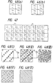
- Figs. 46(a) and 46(b) show other forms of conversion characteristics set by the conversion characteristic selection means 55.
- a function ⁇ 11 of the first gamma characteristic conversion function group, a function ⁇ 33 of the third gamma characteristic conversion function group, a function ⁇ 34 of the third gamma characteristic conversion function group and a function ⁇ 21 of the second gamma characteristic conversion function group are respectively assigned to the pixel data D11, D12, D21 and D22 (Fig. 46(a)).
- a function ⁇ 24 of the second gamma characteristic conversion function group, a function ⁇ 34 of the third gamma characteristic conversion function group, a function ⁇ 31 of the third gamma characteristic conversion function group and a function ⁇ 14 of the first gamma characteristic conversion function group are respectively assigned to the pixel data D13, D14, D23 and D24 (Fig. 46(b)).
- These first and second forms are used in the reverse order after two lines as shown in Fig. 47 and while slightly changing the gamma characteristic conversion functions.
- the pixel data D11 is formed as a main dot and the next pixel data D13 adjacent thereto is formed as a subsidiary dot with separation of one dot from the main dot.
- the pixel data D24 is formed as a main dot and the pixel data D22 is formed as a subsidiary dot with separation of one dot from the main dot so as to be prior to the main dot.
- Figs. 49(a) and 49(b) show other forms of conversion characteristics set by the conversion characteristic selection means 55.
- a function ⁇ 34 of the third gamma characteristic conversion function group, a function ⁇ 21 of the second gamma characteristic conversion function group, a function ⁇ 11 of the first gamma characteristic conversion function group and a function ⁇ 33 of the third gamma characteristic conversion function group are respectively assigned to the pixel data D11, D12, D21 and D22 (Fig. 49(a)).
- a function ⁇ 31 of the third gamma characteristic conversion function group, a function ⁇ 14 of the first gamma characteristic conversion function group, a function ⁇ 24 of the second gamma characteristic conversion function group and a function ⁇ 34 of the third gamma characteristic conversion function group are respectively assigned to the pixel data D13, D14, D23 and D24 (Fig. 49(b)).
- These first and second forms are used in the reverse order after two lines as shown in Fig. 50 and while slightly changing the gamma characteristic conversion functions.
- the pixel data D14 is formed as a main dot and the prior pixel data D12 adjacent thereto is formed as a subsidiary dot with separation of one dot from the main dot.
- the pixel data D21 is formed as a main dot and the pixel data D23 is formed as a subsidiary dot with separation of one dot from the main dot so as to be posterior to the main dot.
- blank portions are formed substantially circularly and separately so that ink for non-dot forming portions can be prevented from peeling wastefully. As a result, a gradation faithful to the density of pixel data can be expressed.
- Fig. 52 shows an example of a fifth function group used instead of the aforementioned second gamma characteristic conversion function group.
- the function group is constituted by gamma characteristic conversion functions ⁇ 51 to ⁇ 54.
- Each of the functions has a characteristic in which: a conversion print data Dc is kept constant to form no dot in a range of from the low density region to the intermediate density region of pixel data; and the conversion print data proportionally increases to a conversion print data D I in a range of from the intermediate density region to the high density region of pixel data.
- Fig. 53 shows a sixth gamma characteristic conversion function group ⁇ 61 to ⁇ 66 used instead of the aforementioned fourth gamma characteristic conversion function group.
- Each of the functions in the sixth group has a characteristic in which: a conversion print data D C is kept constant to form no dot in a range of from the low density region to the intermediate density region of pixel data; and the conversion print data increases to a conversion print data D J in the high density region of pixel data.
- the functions are set to conversion print data which are slightly different by a predetermined quantity for pixel data.
- Fig. 54 shows a printing form in the case where the fifth and sixth function groups shown in Figs. 52 and 53 are used. That is, Fig. 54 shows an example of the form of application in the case where four kinds of functions suitably selected from the first, third, fifth (Fig. 52) and sixth (Fig. 53) gamma characteristic conversion function groups by the conversion characteristic selection means 55 are assigned to pixel data D11, D12, D21 and D22 in the matrix of 2 x 2 pixels selected by the sampling means.
- the pixel data D11 sampled by the sampling means 53 is converted into a conversion print data linearly proportional to the density thereof by one function ⁇ 11 of the gamma characteristic conversion function group of the gamma conversion means 54 selected by the conversion characteristic selection means 55.
- the pixel data D12 is converted into a conversion print data by one function ⁇ 64 of the sixth gamma characteristic conversion function group so that a conversion print data D B is kept constant to form no dot in a range of from the low density region to the intermediate density region of pixel data and then changed to a conversion print data D J in a range of from the intermediate density region to the high density region of pixel data.
- the pixel data D21 is converted into a conversion print data by one function ⁇ 51 of the fifth gamma characteristic conversion function group so that a conversion print data Dc is kept constant to form no dot in a range of from the low density region to the intermediate density region of pixel data and then changed to a conversion print data D I in a range of from the intermediate density region to the high density region of pixel data.
- the pixel data D22 is converted into a conversion print data by one function ⁇ 34 of the third gamma characteristic conversion function group so that energy is not applied in the all regions.
- the pixel data D21 and D22 in the same sampling area are printed. Because the functions ⁇ 51 and ⁇ 34 are respectively assigned to the pixel data D21 and D22, the pixel data D21 alone serves to cover the first-line pixel data D11.
- Fig. 55 printing is continued in the form as shown in Fig. 55, that is, by alternately repeating the form of assignment of gamma characteristic conversion functions while slightly changing the gamma characteristic conversion functions shown in Fig. 54.
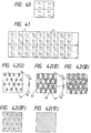
- dots based on the pixel data D11, D13, D31 and D33 are formed. As a result, dots are formed like checkers as shown in Fig. 56(I), so that screen angles of 0 and 90 degrees are set.
- dots based on the fifth and sixth gamma characteristic conversion function groups are formed as shown in Fig. 56(III). Because not only the dots based on the fifth and sixth gamma characteristic conversion function groups are small but the pixel data D21 are not used for forming dots except the maximum density of pixel data, dots are formed while forming one-dot circular blank portions 65. As a result, ink in the blank portions is prevented from peeling wastefully widely, so that dots of a gradation faithful to the density of pixel data can be formed.
- the first, second and third gamma characteristic conversion function groups can be assigned to respective pixels in the sampled matrix data so that the sampling area can be expressed not only through generation of a main dot as a center of image expression and a subsidiary dot adjacent to the main dot on the basis of the first and second gamma characteristic conversion function groups but through addition of a dot based on the third gamma characteristic conversion function group thereto for the maximum density of pixel data.
- the gamma conversion characteristics can be selected by the head density correction data 37 to correct the densities outputted from the respective heating resistor elements 14 of the thermal transfer recording head 6 or may be selected by the thermal history correction data 38 to correct the thermal interference through the printing history.
- Fig. 57 shows a seventh gamma characteristic conversion function group adapted for correction of the thermal history.
- the seventh gamma characteristic conversion function group is constituted by functions ⁇ 71 to ⁇ 74.
- Each of the functions has a characteristic in which: a conversion print data D B , D C , D D or D E sufficiently small to form no dot or to form a minimum-size dot is kept constant in a range of from the low density region to the high density region of pixel data; and the data increases to a conversion print data D I , D J or D K in the maximum density region.
- Fig. 58 shows the case where dots are printed for every second column in the first previous line with respect to a certain line in the paper feeding direction and all dots are printed in the second previous line with respect to the certain line.
- the pixel data D12, D14, (D16 and D18) are assigned for the third gamma characteristic conversion group shown in Fig. 35.
- Fig. 59 shows the case where dots are printed for every second column in the first preceding line with respect to a certain line in the paper feeding direction and dots are also printed for every second column line in the second preceding line with respect to the certain line so that column positions of dots are different between the first preceding line and the second preceding line.
- the pixel data D12, D14, (D16 and D18) are assigned for one function ⁇ 74 of the seventh gamma characteristic function group shown in Fig. 57, which serves to convert the data into a slightly higher conversion print data compared with the third gamma characteristic conversion group shown in Fig. 35.
- Fig. 59 shows the case where dots are printed for every second column in the first preceding line with respect to a certain line in the paper feeding direction and dots are also printed for every second column line in the second preceding line with respect to the certain line so that column positions of dots are different between the first preceding line and the second preceding line.
- the pixel data D12, D14, (D16 and D18) are
- Fig. 60 shows the case where dots are printed for every second column in the first preceding line with respect to a certain line in the paper feeding direction and no dot is printed in the second preceding line with respect to the certain line.
- the pixel data D12, D14, (D16 and D18) are assigned for one function ⁇ 73 higher by one gradation level than the function ⁇ 74 of the seventh gamma characteristic function group.
- Fig. 61 shows the case where no dot is printed in the first preceding line with respect to a certain line in the paper feeding direction and dots are printed for every second column in the second preceding line with respect to the certain line.
- the pixel data D12, D14, (D16 and D18) are assigned for one function ⁇ 72 higher by one gradation level than the function ⁇ 73 of the seventh gamma characteristic function group.
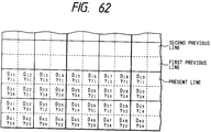
- Fig. 62 shows the case where no dot is printed in the first preceding line with respect to a certain line in the paper feeding direction and no dot is printed in the second preceding line with respect to the certain line.
- the pixel data D12, D14, (D16 and D18) are assigned for one function ⁇ 71 higher by one gradation level than the function ⁇ 72 of the seventh gamma characteristic function group.
- the functions ⁇ 71 to ⁇ 74 constituting the seventh gamma characteristic conversion function group on the basis of the density correction data storage means 56 and the thermal history correction data storage means 57, the functions ⁇ 71 to ⁇ 74 of the seventh gamma characteristic conversion function group to form no dot in a large part of the range can be used for correcting the print density on the basis of the change of the temperature of the substrate 13 (Fig. 3) and the change of the environmental temperature caused by the continuous printing operation. Accordingly, sharp color printing being always stable can be performed regardless of the great change of the printing density.
- the aforementioned correction can be made easily by selection of data, so that no arithmetic operation circuit is required for correcting the thermal history. As a result, the structure of the apparatus can be simplified.
Landscapes
- Engineering & Computer Science (AREA)
- Multimedia (AREA)
- Signal Processing (AREA)
- Electronic Switches (AREA)
Applications Claiming Priority (8)
| Application Number | Priority Date | Filing Date | Title |
|---|---|---|---|
| JP161134/91 | 1991-06-05 | ||
| JP16113491A JP2943408B2 (ja) | 1991-06-05 | 1991-06-05 | 熱転写式画像形成装置 |
| JP23020791A JP2946864B2 (ja) | 1991-09-10 | 1991-09-10 | 熱転写式画像形成装置 |
| JP230205/91 | 1991-09-10 | ||
| JP23020591A JP3094539B2 (ja) | 1991-09-10 | 1991-09-10 | 熱転写式画像形成装置 |
| JP230206/91 | 1991-09-10 | ||
| JP230207/91 | 1991-09-10 | ||
| JP23020691A JP3094540B2 (ja) | 1991-09-10 | 1991-09-10 | 熱転写式画像形成装置 |
Publications (3)
| Publication Number | Publication Date |
|---|---|
| EP0517263A2 true EP0517263A2 (fr) | 1992-12-09 |
| EP0517263A3 EP0517263A3 (en) | 1993-10-13 |
| EP0517263B1 EP0517263B1 (fr) | 1997-04-16 |
Family
ID=27473714
Family Applications (1)
| Application Number | Title | Priority Date | Filing Date |
|---|---|---|---|
| EP92109575A Expired - Lifetime EP0517263B1 (fr) | 1991-06-05 | 1992-06-05 | Appareil de formation d'image par transfert thermique |
Country Status (3)
| Country | Link |
|---|---|
| US (1) | US5359424A (fr) |
| EP (1) | EP0517263B1 (fr) |
| DE (1) | DE69219010T2 (fr) |
Cited By (2)
| Publication number | Priority date | Publication date | Assignee | Title |
|---|---|---|---|---|
| EP0605186A3 (en) * | 1992-12-22 | 1996-02-07 | Tektronix Inc | Systems and methods for thermal transfer printing. |
| EP0947334A1 (fr) * | 1998-04-03 | 1999-10-06 | Alps Electric Co., Ltd. | Procédé pour la formation d'images pour une imprimante à impression par transfert thermique |
Families Citing this family (4)
| Publication number | Priority date | Publication date | Assignee | Title |
|---|---|---|---|---|
| JP3458018B2 (ja) * | 1995-01-19 | 2003-10-20 | 京セラミタ株式会社 | 画像形成装置 |
| JP4198835B2 (ja) * | 1999-08-27 | 2008-12-17 | 株式会社沖データ | 書き込み装置、画像形成装置及びledヘッド |
| EP1420957A4 (fr) * | 2002-03-19 | 2007-12-12 | Ricoh Kk | Procede de correction des differences de couleur dans les imprimantes bidirectionnelles, et imprimante, programme et memoire associes |
| US10121419B2 (en) * | 2015-11-13 | 2018-11-06 | Google Llc | Head mounted display device with rapid gamma correction between display panels |
Family Cites Families (11)
| Publication number | Priority date | Publication date | Assignee | Title |
|---|---|---|---|---|
| DE2262824C3 (de) * | 1972-12-22 | 1975-07-10 | Dr.-Ing. Rudolf Hell Gmbh, 2300 Kiel | Verfahren zur gerasterten Reproduktion farbiger Halbtonbilder im Ein- oder Mehrfarbendruck |
| JPS60240277A (ja) * | 1984-05-15 | 1985-11-29 | Fuji Xerox Co Ltd | 中間調記録方法 |
| JPS6125365A (ja) * | 1984-07-13 | 1986-02-04 | Canon Inc | 中間調画像形成方法 |
| US4884080A (en) * | 1985-01-31 | 1989-11-28 | Kabushiki Kaisha Toshiba | Color image printing apparatus |
| US4890121A (en) * | 1985-01-31 | 1989-12-26 | Kabushiki Kaisha Toshiba | Halftone image printing device |
| JPH0793681B2 (ja) * | 1986-03-31 | 1995-10-09 | 株式会社東芝 | 多階調記録方法 |
| JPS61189774A (ja) * | 1985-02-18 | 1986-08-23 | Ricoh Co Ltd | 多階調画像形成方式 |
| JPH0683374B2 (ja) * | 1986-02-14 | 1994-10-19 | 富士写真フイルム株式会社 | 網点画像の形成方法 |
| DE3806935A1 (de) * | 1988-03-03 | 1989-09-14 | Standard Elektrik Lorenz Ag | Drucker |
| JP2783328B2 (ja) * | 1989-10-17 | 1998-08-06 | キヤノン株式会社 | 画像形成装置 |
| JPH0767821B2 (ja) * | 1990-02-26 | 1995-07-26 | 株式会社リコー | 画像形成方法 |
-
1992
- 1992-06-03 US US07/893,081 patent/US5359424A/en not_active Expired - Lifetime
- 1992-06-05 EP EP92109575A patent/EP0517263B1/fr not_active Expired - Lifetime
- 1992-06-05 DE DE69219010T patent/DE69219010T2/de not_active Expired - Fee Related
Cited By (3)
| Publication number | Priority date | Publication date | Assignee | Title |
|---|---|---|---|---|
| EP0605186A3 (en) * | 1992-12-22 | 1996-02-07 | Tektronix Inc | Systems and methods for thermal transfer printing. |
| EP0947334A1 (fr) * | 1998-04-03 | 1999-10-06 | Alps Electric Co., Ltd. | Procédé pour la formation d'images pour une imprimante à impression par transfert thermique |
| US6226021B1 (en) | 1998-04-03 | 2001-05-01 | Alps Electric Co., Ltd. | Image forming method of thermal transfer printer |
Also Published As
| Publication number | Publication date |
|---|---|
| DE69219010T2 (de) | 1997-11-13 |
| EP0517263B1 (fr) | 1997-04-16 |
| DE69219010D1 (de) | 1997-05-22 |
| US5359424A (en) | 1994-10-25 |
| EP0517263A3 (en) | 1993-10-13 |
Similar Documents
| Publication | Publication Date | Title |
|---|---|---|
| US4910603A (en) | Half-tone image reproduction method and apparatus using partial density ranges | |
| US5006866A (en) | Thermal printing apparatus responsive to estimated stored heat of the heating element | |
| JP4471813B2 (ja) | 画像処理装置、画像形成装置及びプログラム | |
| EP2233302A2 (fr) | Imprimante à jet d'encre et procédé d'impression | |
| JPS5952658A (ja) | 画像形成装置 | |
| JP2004284279A (ja) | 画像処理装置、画像処理方法及び画像処理プログラム | |
| JPH11198452A (ja) | 画像補正方法 | |
| US9067430B2 (en) | Ink jet recording apparatus and recording method | |
| EP0517263B1 (fr) | Appareil de formation d'image par transfert thermique | |
| JP4249365B2 (ja) | 低減を用いたプリント方向誘導性色相シフトの補償 | |
| EP0261801A2 (fr) | Appareil d'enregistrement d'images en couleur | |
| JPH04339464A (ja) | 中間調記録装置 | |
| JP2946864B2 (ja) | 熱転写式画像形成装置 | |
| JP3094539B2 (ja) | 熱転写式画像形成装置 | |
| US6356360B1 (en) | Apparatus and method for rendering halftone dot structures using grey level dots | |
| JP2943408B2 (ja) | 熱転写式画像形成装置 | |
| JP3094540B2 (ja) | 熱転写式画像形成装置 | |
| JP2978672B2 (ja) | 記録装置 | |
| JPH0720199B2 (ja) | 画像処理装置 | |
| EP0501487A2 (fr) | Appareil de restitution d'images par transfert thermique | |
| JP5023954B2 (ja) | 液体噴射ムラの抑制 | |
| JPH0564904A (ja) | 熱転写プリンタ | |
| JP3504475B2 (ja) | 画像形成装置の画像形成方法 | |
| JPH0646274A (ja) | 画像形成装置 | |
| JPH05261962A (ja) | 熱転写式画像形成装置 |
Legal Events
| Date | Code | Title | Description |
|---|---|---|---|
| PUAI | Public reference made under article 153(3) epc to a published international application that has entered the european phase |
Free format text: ORIGINAL CODE: 0009012 |
|
| AK | Designated contracting states |
Kind code of ref document: A2 Designated state(s): DE FR GB IT NL |
|
| PUAL | Search report despatched |
Free format text: ORIGINAL CODE: 0009013 |
|
| AK | Designated contracting states |
Kind code of ref document: A3 Designated state(s): DE FR GB IT NL |
|
| 17P | Request for examination filed |
Effective date: 19931220 |
|
| 17Q | First examination report despatched |
Effective date: 19950829 |
|
| GRAG | Despatch of communication of intention to grant |
Free format text: ORIGINAL CODE: EPIDOS AGRA |
|
| GRAH | Despatch of communication of intention to grant a patent |
Free format text: ORIGINAL CODE: EPIDOS IGRA |
|
| RBV | Designated contracting states (corrected) |
Designated state(s): DE FR GB |
|
| GRAH | Despatch of communication of intention to grant a patent |
Free format text: ORIGINAL CODE: EPIDOS IGRA |
|
| GRAA | (expected) grant |
Free format text: ORIGINAL CODE: 0009210 |
|
| AK | Designated contracting states |
Kind code of ref document: B1 Designated state(s): DE FR GB |
|
| REF | Corresponds to: |
Ref document number: 69219010 Country of ref document: DE Date of ref document: 19970522 |
|
| ET | Fr: translation filed | ||
| PLBE | No opposition filed within time limit |
Free format text: ORIGINAL CODE: 0009261 |
|
| STAA | Information on the status of an ep patent application or granted ep patent |
Free format text: STATUS: NO OPPOSITION FILED WITHIN TIME LIMIT |
|
| 26N | No opposition filed | ||
| REG | Reference to a national code |
Ref country code: GB Ref legal event code: IF02 |
|
| PGFP | Annual fee paid to national office [announced via postgrant information from national office to epo] |
Ref country code: GB Payment date: 20060531 Year of fee payment: 15 |
|
| PGFP | Annual fee paid to national office [announced via postgrant information from national office to epo] |
Ref country code: DE Payment date: 20060601 Year of fee payment: 15 |
|
| PGFP | Annual fee paid to national office [announced via postgrant information from national office to epo] |
Ref country code: FR Payment date: 20060608 Year of fee payment: 15 |
|
| GBPC | Gb: european patent ceased through non-payment of renewal fee |
Effective date: 20070605 |
|
| REG | Reference to a national code |
Ref country code: FR Ref legal event code: ST Effective date: 20080229 |
|
| PG25 | Lapsed in a contracting state [announced via postgrant information from national office to epo] |
Ref country code: DE Free format text: LAPSE BECAUSE OF NON-PAYMENT OF DUE FEES Effective date: 20080101 |
|
| PG25 | Lapsed in a contracting state [announced via postgrant information from national office to epo] |
Ref country code: GB Free format text: LAPSE BECAUSE OF NON-PAYMENT OF DUE FEES Effective date: 20070605 |
|
| PG25 | Lapsed in a contracting state [announced via postgrant information from national office to epo] |
Ref country code: FR Free format text: LAPSE BECAUSE OF NON-PAYMENT OF DUE FEES Effective date: 20070702 |