EP0527009B1 - Frankiermaschine mit nachladbarer tragbarer Steuereinheit - Google Patents
Frankiermaschine mit nachladbarer tragbarer Steuereinheit Download PDFInfo
- Publication number
- EP0527009B1 EP0527009B1 EP19920306829 EP92306829A EP0527009B1 EP 0527009 B1 EP0527009 B1 EP 0527009B1 EP 19920306829 EP19920306829 EP 19920306829 EP 92306829 A EP92306829 A EP 92306829A EP 0527009 B1 EP0527009 B1 EP 0527009B1
- Authority
- EP
- European Patent Office
- Prior art keywords
- postage meter
- meter
- voltage
- rechargeable battery
- switch
- Prior art date
- Legal status (The legal status is an assumption and is not a legal conclusion. Google has not performed a legal analysis and makes no representation as to the accuracy of the status listed.)
- Expired - Lifetime
Links
- 238000012360 testing method Methods 0.000 claims abstract description 16
- 230000000694 effects Effects 0.000 claims description 3
- 230000003213 activating effect Effects 0.000 claims 1
- 230000001419 dependent effect Effects 0.000 claims 1
- OJIJEKBXJYRIBZ-UHFFFAOYSA-N cadmium nickel Chemical compound [Ni].[Cd] OJIJEKBXJYRIBZ-UHFFFAOYSA-N 0.000 description 4
- 238000010586 diagram Methods 0.000 description 3
- 230000006870 function Effects 0.000 description 3
- WHXSMMKQMYFTQS-UHFFFAOYSA-N Lithium Chemical compound [Li] WHXSMMKQMYFTQS-UHFFFAOYSA-N 0.000 description 2
- 239000002253 acid Substances 0.000 description 2
- 239000003990 capacitor Substances 0.000 description 2
- 229910052744 lithium Inorganic materials 0.000 description 2
- 230000003068 static effect Effects 0.000 description 2
- 230000009471 action Effects 0.000 description 1
- 230000004913 activation Effects 0.000 description 1
- 230000008859 change Effects 0.000 description 1
- 230000007423 decrease Effects 0.000 description 1
- 238000001514 detection method Methods 0.000 description 1
- 230000006866 deterioration Effects 0.000 description 1
- 238000005516 engineering process Methods 0.000 description 1
- 238000000034 method Methods 0.000 description 1
- 230000008569 process Effects 0.000 description 1
- 230000001105 regulatory effect Effects 0.000 description 1
Images
Classifications
-
- G—PHYSICS
- G07—CHECKING-DEVICES
- G07B—TICKET-ISSUING APPARATUS; FARE-REGISTERING APPARATUS; FRANKING APPARATUS
- G07B17/00—Franking apparatus
- G07B17/00185—Details internally of apparatus in a franking system, e.g. franking machine at customer or apparatus at post office
- G07B17/00193—Constructional details of apparatus in a franking system
-
- G—PHYSICS
- G07—CHECKING-DEVICES
- G07B—TICKET-ISSUING APPARATUS; FARE-REGISTERING APPARATUS; FRANKING APPARATUS
- G07B17/00—Franking apparatus
- G07B17/00016—Relations between apparatus, e.g. franking machine at customer or apparatus at post office, in a franking system
- G07B17/0008—Communication details outside or between apparatus
- G07B2017/00153—Communication details outside or between apparatus for sending information
- G07B2017/00177—Communication details outside or between apparatus for sending information from a portable device, e.g. a card or a PCMCIA
-
- G—PHYSICS
- G07—CHECKING-DEVICES
- G07B—TICKET-ISSUING APPARATUS; FARE-REGISTERING APPARATUS; FRANKING APPARATUS
- G07B17/00—Franking apparatus
- G07B17/00185—Details internally of apparatus in a franking system, e.g. franking machine at customer or apparatus at post office
- G07B17/00193—Constructional details of apparatus in a franking system
- G07B2017/00241—Modular design
-
- G—PHYSICS
- G07—CHECKING-DEVICES
- G07B—TICKET-ISSUING APPARATUS; FARE-REGISTERING APPARATUS; FRANKING APPARATUS
- G07B17/00—Franking apparatus
- G07B17/00185—Details internally of apparatus in a franking system, e.g. franking machine at customer or apparatus at post office
- G07B17/00193—Constructional details of apparatus in a franking system
- G07B2017/00258—Electronic hardware aspects, e.g. type of circuits used
Definitions
- This invention relates to improved reliability in devices which are connected to AC power when stationary and in use, but which must be powered by a rechargeable battery while away from AC power, and relates particularly to improved reliability in postage meter registers taken to a post office for resetting with additional postage.
- a postage meter is used to print postage at a customer's premises away from the post office.
- a counter on the machine called the descending register, records the quantity of postage that may be printed by one using the postage meter, and this counter is decremented each time a piece of mail is passed through the meter for printing of postage. It is imperative that only the post office and instrumentalities under its control be allowed to add to the descending register, otherwise one could give oneself free postage without paying the post office.
- the postage meter is usually designed so as to be divided into a fixed part (the "base") meant to stay in the customer's premises and a portable part (the "meter portion”) that includes the descending register.
- the base a fixed part
- the meter portion a portable part that includes the descending register.
- the larger power supply is typically a rechargeable battery such as a nickel-cadmium (or lead-acid) sealed battery.
- the base contains a power supply in addition to those mentioned above. During times when the meter is connected to AC power (i.e. through the base) and powered up, the base power supply powers the electronics, recharges the rechargeable batteries, and provides all other power required for any and all meter functions.
- the very small power supply is preferably located as part of a sealed unit with its associated static RAM memory, and for the purposes of this discussion is assumed to be reliable even in the face of loss of power to any and all other parts of the meter.
- the memory device is a CMOS memory and the power supply is a lithium cell, the life is assumed to be on the order of years, because the quiescent power drain of the memory is on the order of microamperes.
- the larger power supply since the power consumed when the electronics are in use (e.g. at the post office) is on the order of tens or hundreds of milliamperes.
- the power supply life is limited by the fact that physical size of the rechargeable battery is constrained and ratio of capacity to size is smaller for rechargeable batteries such as the preferred nickel-cadmium (nicad) batteries than for nonrechargeable batteries.
- GB-A-2072902 discloses battery charger suitable for a postage meter, including a rechargeable battery.
- the battery charger is connected between the backup batteries and the line power supply. Both the backup batteries and the line power supply are connected to a switch which connects the modules either to the line power supply or to the backup batteries.
- an electronic postage meter as set out in claim 1.
- a postage meter in accordance with an embodiment of the invention is shown in functional block diagram in Fig. 1.
- a central processor unit (CPU) 70 communicates by bus 71 with a battery-backed random access memory 72, a keyboard 74, and a display 75.
- the correct time and date are maintained in clock/calendar 73, the contents of which are settable and readable by CPU 70 via bus 71. If the customer requests that postage be printed, and if the meter descending register (contained in the memory 72) contains sufficient funds, then the requested postage is printed at a postage printer 76.
- the processor 70 has numerous discrete inputs and outputs through an I/O port device 77.
- the I/O port 77 has inputs 54 and 55 and outputs 35 and 43, about which more will be said below.
- a power line 25 carries power at +5V for the processor 70 and the related components 72, 74, 75, 76, and 77 and for other components, not shown in Fig. 1 for clarity.
- the power is derived in normal operation from external main power as discussed further below.
- Rechargeable batteries not shown in Fig. 1 provide reserve power via a line 29 to the clock/calendar 73, and at certain times via supply power on the line 25 for system operation as described below.
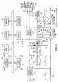
- Fig. 2 there is shown the power supply of the system of Fig. 1.
- the meter is physically and conceptually partitioned into a base 10 and a meter portion 20 where, as mentioned above, the term "meter portion” connotes that portion of the meter that is easily removed from the base and transported to the post office for resetting its descending register.
- a 24 V DC supply 11 in the base 10 receives the publicly supplied AC power (110 V, 60Hz in the United States) through the power cord 12, and supplies +24V of unregulated direct current to meter portion 20 through line 13 and ground 14.
- AC power 110 V, 60Hz in the United States
- the +24V from the base is regulated at a switching power supply 22 to +5V.
- the line 29 provides the +5V to power the clock calendar 73 of the meter portion, and the line 25 provides the +5V to power the rest of the meter portion 20, including the processor 70.
- Rechargeable batteries 30 and 31 are provided, each of which is preferably a 3.6V nickel-cadmium battery with a capacity of 150mAh.
- the batteries are charged continuously when the meter portion is attached to the power supply of the base.
- the base provides a slow charging current, preferably a trickle charge, through current limiting resistor 27 and diode 28.
- a power supply of +24V at point 12 with a load of 3000 ohms provided by the resistor 27 provides a charging current of 5mA.
- the rechargeable batteries 30, 31 are fully charged after about 40 hours with the meter portion attached to the powered base.
- An additional charging current flow path is provided by three-terminal regulators 15, 16, resistors 17, 18, 19, and diode 79, as shown in Fig. 2.
- Regulators 15, 16 are preferably type LM317, resistor 17 is 27 ohms, resistor 18 is 240 ohms, and resistor 19 is 1500 ohms.
- the additional charging current flow path provides a much higher charge current than that of resistor 27 for circumstances where the batteries 30, 31 have been substantially discharged.
- a load resistor 33 may be imposed upon the batteries 30, 31 by turning on a transistor 34, controlled by a discrete output 35 from the CPU.
- a voltage divider of resistors 56, 57 providing a voltage proportional to that of line 44 to a comparator 52.
- the other input of the comparator 52 is a reference voltage of a line 80 derived from the general +5VDC supply of line 25 by way of a three-terminal regulator 60, also shown in Fig. 2.
- Actuation of the switch 36 is an event detectable by CPU 70 as will now be described.
- the voltage at line 37 is divided by the divider of resistors 58, 59 and made available to comparator 53.
- Comparator 53 also receives the above-mentioned reference voltage of line 80.
- the operator initiates the battery test by sending an input signal to the CPU 70 via the keyboard 74 (shown in Fig. 1) requesting a battery test.
- the CPU 70 interprets the input according to a stored program in memory 72, and sends a signal via output port line 35 (shown in both Figs. 1 and 2) which turns on bipolar transistor 34 (shown in Fig. 2), applying a load resistor 33 to the batteries 30, 31.
- the load is selected to be comparable to that required for operation when the meter portion is away from the power provided by the base.
- a resistor preferably 50 ohms and rated at 0.8 W provides a discharge current of about 150mA.
- the stored program of memory 72 sends the CPU 70 into a delay loop of specified duration, depending on how long the batteries are expected to maintain such a load plus a safety factor. For a normal post office resetting session, a three-minute delay loop duration is preferred for testing the rechargeable batteries 30, 31.
- the output signal 35 is shut off, removing load resistor 33 from batteries 30, 31.
- the input signal at line 54 is polled by the CPU 70. If the batteries 30, 31 have not been unduly discharged, the charging current will be moderate and the voltage at line 44 measured by comparator 52 will be high enough to generate an asserted level at line 54.
- the CPU 70 reports the successful test at the display 75. On the other hand, if the batteries 30, 31 have been substantially discharged, the charging current will be greater and the voltage at line 44 measured by comparator 52 will be lower, so that an unasserted level appears at line 54. In the latter case under program control the display 75 warns the operator to wait before bringing the meter portion to the post office. In its application o the load resistor 33, timing of that application and responding to the comparator 54, the CPU acts as test control means.
- the reference voltage at line 80 is 2.5 V and the voltage divider is selected so that the output of comparator 52 changes when the voltage at line 44 reaches 6.25 V.
- the nominal voltage of 6.25 V was selected because to operate at the post office the system is found to work properly if between 6.25 V and 6.0 V is available from the batteries 30, 31.
- the comparator 52 is preferably a high-impedance device in comparison to the load 33.
- the base 10 must stay at the customer's premises, with the consequence that the power at line 13 is no longer available.
- battery 31 maintains the current, normally supplied by the base power supply, to line 29 to maintain the clock/calendar circuit 73.
- the rechargeable battery 31 typically supplies 10uA to the clock/calendar circuit 73.
- the post office representative activates the meter portion 20 for resetting.
- the two batteries 30 and 31 will not power the meter portion through line 25 until such time as the post office lock at switch 36 is activated.
- This switch needs to be held down for only a brief time, namely the duration of the charging of capacitor 39, at which point the current going to the base of transistor 41 will allow current to flow through the relay 40.
- the meter portion 20 may be powered at line 25 through the regulator 32 which decreases the nominal 7.2V offered by the two batteries to the 5V required by the meter portion.
- the CPU 70 Most of the time that the CPU 70 commences execution it is because power has been applied through base 10. Since this means the user is probably a customer and not a post office employee, the CPU 70 follows a stored program that permits only the functions and capabilities allowed to customers. In contrast, if an authorized post office employee is using the meter, it is desired that the employee be able to perform certain activities forbidden to customers. In the meter according to the embodiment the stored program is set up with a "post office" mode in which post office employee activities are possible.
- the CPU 70 does not yet know how or why it has received power.
- the power could be from power supply 22 or from power supply 32, for example.
- Among the many tasks assigned to the CPU 70 during power up as part of its stored program is determining whether or not the CPU should be in post office mode.
- the CPU 70 recognizes that it is to be in post office mode by polling the signal at line 55.
- comparator 53 detects the closing of the switch 36 and annunciates this to the CPU 70 by line 55.
- the CPU 70 asserts signal 43 which causes the system to go into a self-powered mode.
- the relay 40 will remain closed as long as the CPU continues to send the signal at line 43.
- the post office representative is offered, by messages at display 75, the opportunity to change the value of the descending register, to remove all postage from the meter, and other functions forbidden to ordinary users.
- an appropriate entry at keyboard 74 causes the CPU 70 to drop the signal at line 43. This powers down the meter portion 20 except for the continued operation of the clock/calendar 73.
- the action of the CPU 70 in powering down the meter portion 20 by dropping the signal at line 43 is, in the ordinary case, prompted by the completion of the post office task. However, if the batteries 30, 31 reach a point of imminent exhaustion so that power is soon to fail, this will be annunciated to the CPU 70 by the a low-power warning signal not shown in Fig. 2. Upon receipt of the low-power warning signal, the CPU 70 powers down the meter portion 20 prior to the completion of the current post office task.
- the system detects potential failure conditions in addition to the failure of the batteries 30, 31 to be fully charged.
- a shorted cell typically results in a total battery voltage that is reduced by the nominal voltage for that cell. In the case of nickel-cadmium batteries, the result can be a battery voltage reduced by 1.2 volts.
- the load resistor 33 and threshold of comparator 52 may be selected to permit detection of this mode.
- An open cell typically results in an output voltage of zero, which is readily detected by the circuitry.
- the rechargeable battery could be a lead-acid cell or other rechargeable cell.
Landscapes
- Physics & Mathematics (AREA)
- General Physics & Mathematics (AREA)
- Devices For Checking Fares Or Tickets At Control Points (AREA)
- Charge And Discharge Circuits For Batteries Or The Like (AREA)
- Mobile Radio Communication Systems (AREA)
- Management, Administration, Business Operations System, And Electronic Commerce (AREA)
- Cash Registers Or Receiving Machines (AREA)
- Tests Of Electric Status Of Batteries (AREA)
Claims (11)
- Elektronische Frankiermaschine umfassend ein Basisteil (10) und ein bewegliches Teil (20), das mit dem Basisteil verbindbar ist, welches bewegliche Teil Elektronikmittel zur Steuerung des Betriebs der Frankiermaschine und eine nachladbare Batterie (30, 31) zur Versorgung der Elektronikmittel aufweist, wenn das bewegliche Teil nicht mit dem Basisteil verbunden ist, wobei das Basisteil Stromversorgungsmittel (11) aufweist, die mit dem beweglichen Teil elektrisch verbindbar sind, wodurch die Batterie nachgeladen werden kann, wenn der bewegliche Teil mit dem Basisteil verbunden ist, und wodurch die elektronischen Mittel versorgt werden können, wenn das bewegliche Teil mit dem Basisteil verbunden ist, Mittel, z.B. eine Tastatur (74), zum Ermöglichen von Nutzereingaben zu den Elektronikmitteln, und Testmittel, wobei die Testmittel umfassen:ein Lastmittel (33); undSchaltmittel (34), die wahlweise das Lastmittel mit der nachladbaren Batterie verbinden, Mittel (52) zur Erfassung der Spannung der nachladbaren Batterie und zur Erzeugung eines für diese charakteristischen Signals, und Teststeuermittel (70), die auf die Nutzereingabemittel ansprechen, um die Schaltmittel zu veranlassen, das Lastmittel mit der nachladbaren Batterie zu verbinden, um die Schaltmittel zu veranlassen, das Lastmittel von der nachladbaren Batterie zu trennen, und um auf das Signal der Mittel zur Erfassung der Spannung der nachladbaren Batterie zuzugreifen.
- Frankiermaschine gemäß Anspruch 1, bei der die Teststeuermittel Mittel zur Verzögerung der Vollendung der Erfassung der Spannung der nachladbaren Batterie für einen Zeitbereich umfassen, während dessen das Lastmittel mit der nachladbaren Batterie verbunden ist.
- Frankiermaschine gemäß Anspruch 2, bei der die Teststeuermittel einen Prozessor (70) enthalten, der zur Abarbeitung eines gespeicherten Programms betätigbar ist, und die Mittel zur Verzögerung einen gespeicherten Schleifen-Programmteil umfassen.
- Frankiermaschine gemäß Anspruch 2 oder 3, bei der das Lastmittel der Eingangsimpedanz der Elektronikmittel angenähert ist.
- Frankiermaschine gemäß Anspruch 2, 3 oder 4, bei der die Mittel zur Erfassung einen Spannungsvergleicher (52) zum Vergleichen einer Spannung, die von der Batteriespannung abhängig ist, mit einer Referenzspannung (80), z.B. einer Referenzversorgungsspannung, umfassen, wobei eine Absenkung der Spannung auf eine Höhe unterhalb der der Referenzspannung auf den Zeitbereich folgend, wenn das Lastmittel mit den Batterien verbunden ist, eine genügende Ladung der Batterien anzeigt.
- Frankiermaschine gemäß Anspruch 5, bei der die Teststeuermittel betätigbar sind, um einen Datenabruf eines Ausgangssignals zu bewirken, das für den Vergleicherzustand bezeichnend ist, um zu bestimmen, ob die Batterienachladung zum Betrieb der Elektronikmittel getrennt vom Basisteil ausreichend ist.
- Frankiermaschine gemäß einem der Ansprüche 1 bis 6, wobei das bewegliche Teil einen Zählerteilbereich (20) umfaßt, der die Menge der zum Drucken verfügbaren Post anzeigt, und die Elektronikmittel zur Freigabe eines Rücksetzens eines absteigenden Registers des Basisteils umfassen, wenn das bewegliche Teil vom Basisteil getrennt ist.
- Frankiermaschine gemäß einem der Ansprüche 1 bis 7, bei der die Schaltmittel einen Bipolar-Transistor umfassen.
- Frankiermaschine gemäß einem der vorhergehenden Ansprüche, bei der ferner Handschaltmittel (36), die eine Versorgungsspannung von der nachladbaren Batterie zu den Elektronikmitteln unter manueller Steuerung bereitstellen, und Steuerschaltmittel zur Bereitstellung einer Versorgungsspannung von der nachladbaren Batterie zu den Elektronikmitteln auf eine manuelle Betätigung der Handschaltmittel vorgesehen sind, wobei die Elektronikmittel Steuerausgabemittel (70) enthalten, die zur Aktivierung der Steuerschaltmittel mit den Steuerschaltmitteln verbunden sind.
- Frankiermaschine gemäß Anspruch 9, die ferner Nachlademittel (27, 28) enthält, wodurch die Batterie nachgeladen werden kann, wenn der bewegliche Zählerteilbereich mit dem Basisteil verbunden ist, wobei die Steuerschaltmittel erste Schaltsteuermittel (41) zur Bereitstellung eines Steuerschaltsignals, nachdem das Handschaltmittel (36) die Versorgungsspannung zu den Elektronikmitteln bereitgestellt hat, und zweite Schaltsteuermittel (40) enthält, die auf das erste Schaltsteuersignal zur Bewirkung einer Energiezufuhr von der nachladbaren Batterie zu den Elektronikmitteln auf eine manuelle Betätigung der Handschaltmittel folgend ansprechen.
- Frankiermaschine gemäß Anspruch 10, bei der das bewegliche Teil (20) ein Register umfaßt, das die Menge der zum Drucken verfügbaren Post anzeigt, und die Elektronikmittel ferner Mittel zur Freigabe eines Rücksetzens des Registers umfassen, wenn das bewegliche Teil von der Spannungsquelle getrennt ist.
Applications Claiming Priority (2)
| Application Number | Priority Date | Filing Date | Title |
|---|---|---|---|
| US740795 | 1991-08-06 | ||
| US07/740,795 US5278541A (en) | 1991-08-06 | 1991-08-06 | Enhanced reliability in portable rechargeable devices |
Publications (3)
| Publication Number | Publication Date |
|---|---|
| EP0527009A2 EP0527009A2 (de) | 1993-02-10 |
| EP0527009A3 EP0527009A3 (de) | 1994-01-19 |
| EP0527009B1 true EP0527009B1 (de) | 1997-09-03 |
Family
ID=24978109
Family Applications (1)
| Application Number | Title | Priority Date | Filing Date |
|---|---|---|---|
| EP19920306829 Expired - Lifetime EP0527009B1 (de) | 1991-08-06 | 1992-07-27 | Frankiermaschine mit nachladbarer tragbarer Steuereinheit |
Country Status (8)
| Country | Link |
|---|---|
| US (1) | US5278541A (de) |
| EP (1) | EP0527009B1 (de) |
| JP (1) | JPH05314135A (de) |
| AT (1) | ATE157789T1 (de) |
| CA (1) | CA2072440A1 (de) |
| DE (1) | DE69221975T2 (de) |
| DK (1) | DK0527009T3 (de) |
| ES (1) | ES2109318T3 (de) |
Families Citing this family (16)
| Publication number | Priority date | Publication date | Assignee | Title |
|---|---|---|---|---|
| US5686887A (en) * | 1994-12-07 | 1997-11-11 | Schoeferisch Aeusserung Anstalt | Electronic locating device |
| US6176178B1 (en) | 1995-03-07 | 2001-01-23 | Ascom Hasler Mailing Systems Ag | Tamper-resistant postage meter |
| US5706727A (en) * | 1995-03-14 | 1998-01-13 | Ascom Hasler Mailing Systems Ag | Postage meter with improved paper path |
| US5719381A (en) * | 1995-04-14 | 1998-02-17 | Ascom Hasler Mailing Systems Ag | Postage meter with hollow rotor axle |
| US5668973A (en) * | 1995-04-14 | 1997-09-16 | Ascom Hasler Mailing Systems Ag | Protection system for critical memory information |
| US5654614A (en) * | 1995-04-14 | 1997-08-05 | Ascom Hasler Mailing Systems Ag | Single-motor setting and printing postage meter |
| US5746133A (en) * | 1995-05-22 | 1998-05-05 | Ascom Hasler Mailing Systems Ag | Postage meter with rotor movement and die cover sensor |
| US5712542A (en) * | 1995-05-25 | 1998-01-27 | Ascom Hasler Mailing Systems Ag | Postage meter with improved handling of power failure |
| US5689098A (en) * | 1995-05-26 | 1997-11-18 | Ascom Hasler Mailing Systems Ag | Postage meter with improved postal lock |
| US6539393B1 (en) * | 1999-09-30 | 2003-03-25 | Hill-Rom Services, Inc. | Portable locator system |
| DE20020635U1 (de) * | 2000-11-28 | 2001-03-15 | Francotyp-Postalia AG & Co., 16547 Birkenwerder | Anordnung zur Stromversorgung für einen Sicherheitsbereich eines Gerätes |
| US9192522B2 (en) | 2003-05-02 | 2015-11-24 | Eveready Battery Company, Inc. | Tampon assembly having shaped pledget |
| US7451929B2 (en) * | 2005-02-28 | 2008-11-18 | Symbol Technologies, Inc. | Methods and apparatus for monitoring electrical contacts |
| WO2007146270A2 (en) | 2006-06-12 | 2007-12-21 | Playtex Products, Inc. | Tampon assembly providing proper bodily placement of a pledget |
| US7496386B2 (en) * | 2006-10-24 | 2009-02-24 | Cisco Technology, Inc. | Rechargeable battery facilitated customer-premises equipment |
| US10957445B2 (en) | 2017-10-05 | 2021-03-23 | Hill-Rom Services, Inc. | Caregiver and staff information system |
Citations (1)
| Publication number | Priority date | Publication date | Assignee | Title |
|---|---|---|---|---|
| EP0373419A2 (de) * | 1988-12-12 | 1990-06-20 | Siemens Aktiengesellschaft | Batterieladegerät für ein medizinisches Gerät |
Family Cites Families (21)
| Publication number | Priority date | Publication date | Assignee | Title |
|---|---|---|---|---|
| US4206450A (en) * | 1974-12-26 | 1980-06-03 | Bowmar Instrument Corporation | Fire and intrusion security system |
| US4025916A (en) * | 1975-10-14 | 1977-05-24 | Goodyear Aerospace Corporation | Battery condition monitoring method and apparatus |
| US4024523A (en) * | 1975-10-14 | 1977-05-17 | Goodyear Aerospace Corporation | Battery condition monitoring method and apparatus |
| US4275274A (en) * | 1979-05-29 | 1981-06-23 | English Tim G | Audio visual monitoring system for announcing a message upon detection of a monitored condition |
| US4323987A (en) * | 1980-03-28 | 1982-04-06 | Pitney Bowes Inc. | Power failure memory support system |
| US4397317A (en) * | 1980-04-17 | 1983-08-09 | Villa Real Antony Euclid C | Electronic blood pressure and pulse rate calculator with optional temperature indicator, timer and memory |
| US4316185A (en) * | 1980-07-17 | 1982-02-16 | General Electric Company | Battery monitor circuit |
| US4316133A (en) * | 1980-09-05 | 1982-02-16 | Westinghouse Electric Corp. | Temperature compensated battery charging system with testing for battery back-up system |
| US4426612A (en) * | 1982-04-16 | 1984-01-17 | Baxter Travenol Laboratories, Inc. | Battery charging and testing circuit |
| US4544910A (en) * | 1982-05-10 | 1985-10-01 | Max Hoberman | Exit sign lamp flashing system with self-checking provisions |
| US4455523A (en) * | 1982-06-07 | 1984-06-19 | Norand Corporation | Portable battery powered system |
| US4581606A (en) * | 1982-08-30 | 1986-04-08 | Isotec Industries Limited | Central monitor for home security system |
| US4517517A (en) * | 1982-09-30 | 1985-05-14 | The United States Of America As Represented By The Secretary Of The Air Force | Nickel-cadmium battery conditioner and tester apparatus |
| US4563628A (en) * | 1982-10-12 | 1986-01-07 | Baker Industries, Inc. | Supervision system for monitoring the condition of a battery and a series-connected fuse |
| US4644245A (en) * | 1985-01-28 | 1987-02-17 | Applied Electro Mechanics, Inc. | Nickel-cadmium battery state-of-charge measuring method |
| GB2173738B (en) * | 1985-04-19 | 1989-07-12 | Roneo Alcatel Ltd | Secure transport of information between electronic stations |
| US4644142A (en) * | 1985-11-06 | 1987-02-17 | F.M.E. Corporation | Modular universal postage meter |
| US4916438A (en) * | 1987-10-16 | 1990-04-10 | Oneac Corporation | Battery charging, monitoring and alarm circuit |
| US4962347A (en) * | 1988-02-25 | 1990-10-09 | Strategic Energy, Ltd. | Flashlight with battery tester |
| GB8820528D0 (en) * | 1988-08-31 | 1988-09-28 | Amoco Corp | Battery tester |
| US5130658A (en) * | 1990-02-28 | 1992-07-14 | Display Matrix Corporation | Apparatus and method for indicating state of charge of a battery |
-
1991
- 1991-08-06 US US07/740,795 patent/US5278541A/en not_active Expired - Lifetime
-
1992
- 1992-06-26 CA CA002072440A patent/CA2072440A1/en not_active Abandoned
- 1992-07-20 JP JP19225392A patent/JPH05314135A/ja active Pending
- 1992-07-27 DK DK92306829T patent/DK0527009T3/da active
- 1992-07-27 ES ES92306829T patent/ES2109318T3/es not_active Expired - Lifetime
- 1992-07-27 DE DE69221975T patent/DE69221975T2/de not_active Expired - Fee Related
- 1992-07-27 AT AT92306829T patent/ATE157789T1/de not_active IP Right Cessation
- 1992-07-27 EP EP19920306829 patent/EP0527009B1/de not_active Expired - Lifetime
Patent Citations (1)
| Publication number | Priority date | Publication date | Assignee | Title |
|---|---|---|---|---|
| EP0373419A2 (de) * | 1988-12-12 | 1990-06-20 | Siemens Aktiengesellschaft | Batterieladegerät für ein medizinisches Gerät |
Also Published As
| Publication number | Publication date |
|---|---|
| DE69221975T2 (de) | 1998-03-05 |
| ES2109318T3 (es) | 1998-01-16 |
| DK0527009T3 (da) | 1997-09-29 |
| DE69221975D1 (de) | 1997-10-09 |
| CA2072440A1 (en) | 1993-02-07 |
| US5278541A (en) | 1994-01-11 |
| EP0527009A3 (de) | 1994-01-19 |
| JPH05314135A (ja) | 1993-11-26 |
| ATE157789T1 (de) | 1997-09-15 |
| EP0527009A2 (de) | 1993-02-10 |
Similar Documents
| Publication | Publication Date | Title |
|---|---|---|
| EP0527009B1 (de) | Frankiermaschine mit nachladbarer tragbarer Steuereinheit | |
| EP0124092B2 (de) | Elektronische Frankiermaschine und Datenlösch- und -schreibverfahren in einem nichtflüchtigen Speicher | |
| AU748979B2 (en) | Portable electronic apparatus with a circuit for controlling discharging of a battery, and a method associated with said circuit | |
| US4323987A (en) | Power failure memory support system | |
| US5341503A (en) | Battery operated computer having improved battery gauge and system for measuring battery charge | |
| EP0448767B1 (de) | Batteriesystem | |
| EP1209794B1 (de) | Stromversorgungsgeräte für tragbare elektrische Geräte | |
| US4984185A (en) | Portable computer having a battery voltage detecting circuit | |
| US6501249B1 (en) | Battery management system | |
| US20120327749A1 (en) | Electric Power System for Portable Electronic Device Having a Timekeeping Circuit | |
| US4628457A (en) | Postal rate memory module with integral battery power | |
| EP0448755A1 (de) | Intelligentes System für eine Batterie | |
| JPH0321952B2 (de) | ||
| JPH07213605A (ja) | バッテリーバックアップ付き注入ポンプ | |
| JPH069432B2 (ja) | バッテリ−の充電状態表示装置 | |
| EP0484745A2 (de) | Gerät zur Rechnerstromversorgungssteuerung | |
| KR20180115125A (ko) | 에너지 저장 장치의 과방전 방지 및 재기동 장치 및 방법 | |
| JPH05189095A (ja) | 電子装置 | |
| EP0484803A2 (de) | Verfahren und Schaltungsanordnung für Stromversorgung | |
| JP2003103871A (ja) | プリンタ用電源切り換え制御方法およびプリンタ用電源装置 | |
| US4578758A (en) | Electronic postage meter having a regulated power supply system responsive to a voltage developed in a transformer primary winding circuit | |
| JPH09109518A (ja) | 電源制御装置および電子機器の電源制御方法 | |
| JPH1138106A (ja) | 電子装置 | |
| KR890002873Y1 (ko) | 자동 판매기의 정전시 보상 회로 | |
| JPH1040351A (ja) | Icメモリカード |
Legal Events
| Date | Code | Title | Description |
|---|---|---|---|
| PUAI | Public reference made under article 153(3) epc to a published international application that has entered the european phase |
Free format text: ORIGINAL CODE: 0009012 |
|
| AK | Designated contracting states |
Kind code of ref document: A2 Designated state(s): AT BE CH DE DK ES FR GB IT LI NL PT SE |
|
| PUAL | Search report despatched |
Free format text: ORIGINAL CODE: 0009013 |
|
| AK | Designated contracting states |
Kind code of ref document: A3 Designated state(s): AT BE CH DE DK ES FR GB IT LI NL PT SE |
|
| 17P | Request for examination filed |
Effective date: 19940708 |
|
| 17Q | First examination report despatched |
Effective date: 19950427 |
|
| RAP1 | Party data changed (applicant data changed or rights of an application transferred) |
Owner name: ASCOM HASLER MAILING SYSTEMS AG |
|
| GRAG | Despatch of communication of intention to grant |
Free format text: ORIGINAL CODE: EPIDOS AGRA |
|
| GRAH | Despatch of communication of intention to grant a patent |
Free format text: ORIGINAL CODE: EPIDOS IGRA |
|
| GRAH | Despatch of communication of intention to grant a patent |
Free format text: ORIGINAL CODE: EPIDOS IGRA |
|
| GRAA | (expected) grant |
Free format text: ORIGINAL CODE: 0009210 |
|
| AK | Designated contracting states |
Kind code of ref document: B1 Designated state(s): AT BE CH DE DK ES FR GB IT LI NL PT SE |
|
| REF | Corresponds to: |
Ref document number: 157789 Country of ref document: AT Date of ref document: 19970915 Kind code of ref document: T |
|
| REG | Reference to a national code |
Ref country code: CH Ref legal event code: EP |
|
| REG | Reference to a national code |
Ref country code: DK Ref legal event code: T3 |
|
| REF | Corresponds to: |
Ref document number: 69221975 Country of ref document: DE Date of ref document: 19971009 |
|
| ET | Fr: translation filed | ||
| ITF | It: translation for a ep patent filed | ||
| REG | Reference to a national code |
Ref country code: PT Ref legal event code: SC4A Free format text: AVAILABILITY OF NATIONAL TRANSLATION Effective date: 19970908 |
|
| REG | Reference to a national code |
Ref country code: ES Ref legal event code: FG2A Ref document number: 2109318 Country of ref document: ES Kind code of ref document: T3 |
|
| REG | Reference to a national code |
Ref country code: CH Ref legal event code: NV Representative=s name: A. BRAUN, BRAUN, HERITIER, ESCHMANN AG PATENTANWAE |
|
| PLBE | No opposition filed within time limit |
Free format text: ORIGINAL CODE: 0009261 |
|
| STAA | Information on the status of an ep patent application or granted ep patent |
Free format text: STATUS: NO OPPOSITION FILED WITHIN TIME LIMIT |
|
| 26N | No opposition filed | ||
| PGFP | Annual fee paid to national office [announced via postgrant information from national office to epo] |
Ref country code: PT Payment date: 19990728 Year of fee payment: 8 |
|
| PG25 | Lapsed in a contracting state [announced via postgrant information from national office to epo] |
Ref country code: PT Free format text: LAPSE BECAUSE OF NON-PAYMENT OF DUE FEES Effective date: 20010131 |
|
| REG | Reference to a national code |
Ref country code: PT Ref legal event code: MM4A Free format text: LAPSE DUE TO NON-PAYMENT OF FEES Effective date: 20010131 |
|
| REG | Reference to a national code |
Ref country code: GB Ref legal event code: IF02 |
|
| PGFP | Annual fee paid to national office [announced via postgrant information from national office to epo] |
Ref country code: AT Payment date: 20020606 Year of fee payment: 11 |
|
| PGFP | Annual fee paid to national office [announced via postgrant information from national office to epo] |
Ref country code: DK Payment date: 20020611 Year of fee payment: 11 |
|
| PGFP | Annual fee paid to national office [announced via postgrant information from national office to epo] |
Ref country code: SE Payment date: 20020617 Year of fee payment: 11 Ref country code: CH Payment date: 20020617 Year of fee payment: 11 |
|
| PGFP | Annual fee paid to national office [announced via postgrant information from national office to epo] |
Ref country code: NL Payment date: 20020619 Year of fee payment: 11 |
|
| PGFP | Annual fee paid to national office [announced via postgrant information from national office to epo] |
Ref country code: ES Payment date: 20020705 Year of fee payment: 11 |
|
| PGFP | Annual fee paid to national office [announced via postgrant information from national office to epo] |
Ref country code: BE Payment date: 20020724 Year of fee payment: 11 |
|
| PG25 | Lapsed in a contracting state [announced via postgrant information from national office to epo] |
Ref country code: AT Free format text: LAPSE BECAUSE OF NON-PAYMENT OF DUE FEES Effective date: 20030727 |
|
| PG25 | Lapsed in a contracting state [announced via postgrant information from national office to epo] |
Ref country code: SE Free format text: LAPSE BECAUSE OF NON-PAYMENT OF DUE FEES Effective date: 20030728 Ref country code: ES Free format text: LAPSE BECAUSE OF NON-PAYMENT OF DUE FEES Effective date: 20030728 |
|
| PG25 | Lapsed in a contracting state [announced via postgrant information from national office to epo] |
Ref country code: LI Free format text: LAPSE BECAUSE OF NON-PAYMENT OF DUE FEES Effective date: 20030731 Ref country code: DK Free format text: LAPSE BECAUSE OF NON-PAYMENT OF DUE FEES Effective date: 20030731 Ref country code: CH Free format text: LAPSE BECAUSE OF NON-PAYMENT OF DUE FEES Effective date: 20030731 Ref country code: BE Free format text: LAPSE BECAUSE OF NON-PAYMENT OF DUE FEES Effective date: 20030731 |
|
| BERE | Be: lapsed |
Owner name: *ASCOM HASLER MAILING SYSTEMS A.G. Effective date: 20030731 |
|
| PG25 | Lapsed in a contracting state [announced via postgrant information from national office to epo] |
Ref country code: NL Free format text: LAPSE BECAUSE OF NON-PAYMENT OF DUE FEES Effective date: 20040201 |
|
| EUG | Se: european patent has lapsed | ||
| REG | Reference to a national code |
Ref country code: CH Ref legal event code: PL Ref country code: DK Ref legal event code: EBP |
|
| NLV4 | Nl: lapsed or anulled due to non-payment of the annual fee |
Effective date: 20040201 |
|
| REG | Reference to a national code |
Ref country code: ES Ref legal event code: FD2A Effective date: 20030728 |
|
| PGFP | Annual fee paid to national office [announced via postgrant information from national office to epo] |
Ref country code: IT Payment date: 20060731 Year of fee payment: 15 |
|
| PGFP | Annual fee paid to national office [announced via postgrant information from national office to epo] |
Ref country code: DE Payment date: 20080722 Year of fee payment: 17 |
|
| PGFP | Annual fee paid to national office [announced via postgrant information from national office to epo] |
Ref country code: FR Payment date: 20080715 Year of fee payment: 17 |
|
| PGFP | Annual fee paid to national office [announced via postgrant information from national office to epo] |
Ref country code: GB Payment date: 20080722 Year of fee payment: 17 |
|
| PG25 | Lapsed in a contracting state [announced via postgrant information from national office to epo] |
Ref country code: IT Free format text: LAPSE BECAUSE OF NON-PAYMENT OF DUE FEES Effective date: 20070727 |
|
| GBPC | Gb: european patent ceased through non-payment of renewal fee |
Effective date: 20090727 |
|
| REG | Reference to a national code |
Ref country code: FR Ref legal event code: ST Effective date: 20100331 |
|
| PG25 | Lapsed in a contracting state [announced via postgrant information from national office to epo] |
Ref country code: FR Free format text: LAPSE BECAUSE OF NON-PAYMENT OF DUE FEES Effective date: 20090731 |
|
| PG25 | Lapsed in a contracting state [announced via postgrant information from national office to epo] |
Ref country code: GB Free format text: LAPSE BECAUSE OF NON-PAYMENT OF DUE FEES Effective date: 20090727 |
|
| PG25 | Lapsed in a contracting state [announced via postgrant information from national office to epo] |
Ref country code: DE Free format text: LAPSE BECAUSE OF NON-PAYMENT OF DUE FEES Effective date: 20100202 |