EP0539211A2 - Procédé de fabrication d'un matériau de remplissage conducteur du type à microcapsule - Google Patents
Procédé de fabrication d'un matériau de remplissage conducteur du type à microcapsule Download PDFInfo
- Publication number
- EP0539211A2 EP0539211A2 EP92309717A EP92309717A EP0539211A2 EP 0539211 A2 EP0539211 A2 EP 0539211A2 EP 92309717 A EP92309717 A EP 92309717A EP 92309717 A EP92309717 A EP 92309717A EP 0539211 A2 EP0539211 A2 EP 0539211A2
- Authority
- EP
- European Patent Office
- Prior art keywords
- minute
- conductive particles
- type conductive
- adhesive agent
- particles
- Prior art date
- Legal status (The legal status is an assumption and is not a legal conclusion. Google has not performed a legal analysis and makes no representation as to the accuracy of the status listed.)
- Granted
Links
Images





Classifications
-
- H—ELECTRICITY
- H01—ELECTRIC ELEMENTS
- H01B—CABLES; CONDUCTORS; INSULATORS; SELECTION OF MATERIALS FOR THEIR CONDUCTIVE, INSULATING OR DIELECTRIC PROPERTIES
- H01B1/00—Conductors or conductive bodies characterised by the conductive materials; Selection of materials as conductors
- H01B1/20—Conductive material dispersed in non-conductive organic material
- H01B1/22—Conductive material dispersed in non-conductive organic material the conductive material comprising metals or alloys
-
- H—ELECTRICITY
- H10—SEMICONDUCTOR DEVICES; ELECTRIC SOLID-STATE DEVICES NOT OTHERWISE PROVIDED FOR
- H10W—GENERIC PACKAGES, INTERCONNECTIONS, CONNECTORS OR OTHER CONSTRUCTIONAL DETAILS OF DEVICES COVERED BY CLASS H10
- H10W20/00—Interconnections in chips, wafers or substrates
- H10W20/40—Interconnections external to wafers or substrates, e.g. back-end-of-line [BEOL] metallisations or vias connecting to gate electrodes
-
- H—ELECTRICITY
- H10—SEMICONDUCTOR DEVICES; ELECTRIC SOLID-STATE DEVICES NOT OTHERWISE PROVIDED FOR
- H10W—GENERIC PACKAGES, INTERCONNECTIONS, CONNECTORS OR OTHER CONSTRUCTIONAL DETAILS OF DEVICES COVERED BY CLASS H10
- H10W70/00—Package substrates; Interposers; Redistribution layers [RDL]
- H10W70/60—Insulating or insulated package substrates; Interposers; Redistribution layers
- H10W70/62—Insulating or insulated package substrates; Interposers; Redistribution layers characterised by their interconnections
- H10W70/66—Conductive materials thereof
- H10W70/666—Organic materials or pastes
-
- H—ELECTRICITY
- H05—ELECTRIC TECHNIQUES NOT OTHERWISE PROVIDED FOR
- H05K—PRINTED CIRCUITS; CASINGS OR CONSTRUCTIONAL DETAILS OF ELECTRIC APPARATUS; MANUFACTURE OF ASSEMBLAGES OF ELECTRICAL COMPONENTS
- H05K3/00—Apparatus or processes for manufacturing printed circuits
- H05K3/30—Assembling printed circuits with electric components, e.g. with resistors
- H05K3/32—Assembling printed circuits with electric components, e.g. with resistors electrically connecting electric components or wires to printed circuits
- H05K3/321—Assembling printed circuits with electric components, e.g. with resistors electrically connecting electric components or wires to printed circuits by conductive adhesives
-
- H—ELECTRICITY
- H10—SEMICONDUCTOR DEVICES; ELECTRIC SOLID-STATE DEVICES NOT OTHERWISE PROVIDED FOR
- H10W—GENERIC PACKAGES, INTERCONNECTIONS, CONNECTORS OR OTHER CONSTRUCTIONAL DETAILS OF DEVICES COVERED BY CLASS H10
- H10W70/00—Package substrates; Interposers; Redistribution layers [RDL]
- H10W70/40—Leadframes
- H10W70/411—Chip-supporting parts, e.g. die pads
- H10W70/417—Bonding materials between chips and die pads
-
- H—ELECTRICITY
- H10—SEMICONDUCTOR DEVICES; ELECTRIC SOLID-STATE DEVICES NOT OTHERWISE PROVIDED FOR
- H10W—GENERIC PACKAGES, INTERCONNECTIONS, CONNECTORS OR OTHER CONSTRUCTIONAL DETAILS OF DEVICES COVERED BY CLASS H10
- H10W72/00—Interconnections or connectors in packages
- H10W72/01—Manufacture or treatment
- H10W72/012—Manufacture or treatment of bump connectors, dummy bumps or thermal bumps
- H10W72/01221—Manufacture or treatment of bump connectors, dummy bumps or thermal bumps using local deposition
- H10W72/01225—Manufacture or treatment of bump connectors, dummy bumps or thermal bumps using local deposition in solid form, e.g. by using a powder or by stud bumping
-
- H—ELECTRICITY
- H10—SEMICONDUCTOR DEVICES; ELECTRIC SOLID-STATE DEVICES NOT OTHERWISE PROVIDED FOR
- H10W—GENERIC PACKAGES, INTERCONNECTIONS, CONNECTORS OR OTHER CONSTRUCTIONAL DETAILS OF DEVICES COVERED BY CLASS H10
- H10W72/00—Interconnections or connectors in packages
- H10W72/071—Connecting or disconnecting
- H10W72/073—Connecting or disconnecting of die-attach connectors
-
- H—ELECTRICITY
- H10—SEMICONDUCTOR DEVICES; ELECTRIC SOLID-STATE DEVICES NOT OTHERWISE PROVIDED FOR
- H10W—GENERIC PACKAGES, INTERCONNECTIONS, CONNECTORS OR OTHER CONSTRUCTIONAL DETAILS OF DEVICES COVERED BY CLASS H10
- H10W72/00—Interconnections or connectors in packages
- H10W72/071—Connecting or disconnecting
- H10W72/073—Connecting or disconnecting of die-attach connectors
- H10W72/07331—Connecting techniques
-
- H—ELECTRICITY
- H10—SEMICONDUCTOR DEVICES; ELECTRIC SOLID-STATE DEVICES NOT OTHERWISE PROVIDED FOR
- H10W—GENERIC PACKAGES, INTERCONNECTIONS, CONNECTORS OR OTHER CONSTRUCTIONAL DETAILS OF DEVICES COVERED BY CLASS H10
- H10W72/00—Interconnections or connectors in packages
- H10W72/20—Bump connectors, e.g. solder bumps or copper pillars; Dummy bumps; Thermal bumps
- H10W72/251—Materials
-
- H—ELECTRICITY
- H10—SEMICONDUCTOR DEVICES; ELECTRIC SOLID-STATE DEVICES NOT OTHERWISE PROVIDED FOR
- H10W—GENERIC PACKAGES, INTERCONNECTIONS, CONNECTORS OR OTHER CONSTRUCTIONAL DETAILS OF DEVICES COVERED BY CLASS H10
- H10W72/00—Interconnections or connectors in packages
- H10W72/30—Die-attach connectors
- H10W72/321—Structures or relative sizes of die-attach connectors
- H10W72/325—Die-attach connectors having a filler embedded in a matrix
-
- H—ELECTRICITY
- H10—SEMICONDUCTOR DEVICES; ELECTRIC SOLID-STATE DEVICES NOT OTHERWISE PROVIDED FOR
- H10W—GENERIC PACKAGES, INTERCONNECTIONS, CONNECTORS OR OTHER CONSTRUCTIONAL DETAILS OF DEVICES COVERED BY CLASS H10
- H10W72/00—Interconnections or connectors in packages
- H10W72/30—Die-attach connectors
- H10W72/351—Materials of die-attach connectors
-
- H—ELECTRICITY
- H10—SEMICONDUCTOR DEVICES; ELECTRIC SOLID-STATE DEVICES NOT OTHERWISE PROVIDED FOR
- H10W—GENERIC PACKAGES, INTERCONNECTIONS, CONNECTORS OR OTHER CONSTRUCTIONAL DETAILS OF DEVICES COVERED BY CLASS H10
- H10W72/00—Interconnections or connectors in packages
- H10W72/30—Die-attach connectors
- H10W72/351—Materials of die-attach connectors
- H10W72/352—Materials of die-attach connectors comprising metals or metalloids, e.g. solders
-
- H—ELECTRICITY
- H10—SEMICONDUCTOR DEVICES; ELECTRIC SOLID-STATE DEVICES NOT OTHERWISE PROVIDED FOR
- H10W—GENERIC PACKAGES, INTERCONNECTIONS, CONNECTORS OR OTHER CONSTRUCTIONAL DETAILS OF DEVICES COVERED BY CLASS H10
- H10W72/00—Interconnections or connectors in packages
- H10W72/30—Die-attach connectors
- H10W72/351—Materials of die-attach connectors
- H10W72/353—Materials of die-attach connectors not comprising solid metals or solid metalloids, e.g. ceramics
- H10W72/354—Materials of die-attach connectors not comprising solid metals or solid metalloids, e.g. ceramics comprising polymers
Definitions
- This invention relates to a method for the production of a microcapsule (MC) type conductive filler and more particularly to a method for coating the surface of minute conductive particles with an insulating polymer and to an MC type adhesive agent having dispersed in an adhesive agent the coated MC type conductive filler.
- MC microcapsule
- the conventional method is effectively applicable only to a limited number of materials because of the heat factor.
- the organic-inorganic composite conductive adhesive agent that is composed of a binder using a synthetic resin as a main component thereof and a conductive filler using a metal powder as a main component thereof finds utility in a wide variety of applications that involving different kinds of materials subjected to adhesion.
- This adhesive agent is an indispensable medium for conductive adhesion of plastic substances (such as epoxy and phenol resins) that do not adhere by soft soldering, for adhesion of NESA glass used in liquid crystal display devices, for adhesion of phosphor bronze with a carbon brush used in micrometers, and for adhesion of lead wires as in quartz oscillators and sdc meters, for example.
- plastic substances such as epoxy and phenol resins
- a resin binder for conductive adhesive agents While epoxy resin is generally used, polyimide type, phenol type, and polyester type resins are also used, though only partially.
- a conductive filler minute particles of such metals as gold, silver, and copper and amorphous carbon and graphite powder are generally used as well as metal oxides, though only partially.
- Silver powder is preferably used over the conductive fillers cited above because it is inexpensive, reliable and effective.
- the conductive adhesive agent is advantageous in various respects compared with conventional applications such as soft soldering and welding though it is not perfectly free from fault.
- this conductive adhesive agent is used between an LSI chip and patterns for mounting component parts, for example, an increase in the amount of minute conductive particles that are incorporated in the conductive adhesive agent lowers insulation resistance as illustrated in Fig. 1 and increases the possibility of adjacent patterns forming electric continuity. A reduction in the amount of minute conductive particles reduces the electric continuity between the LSI and the patterns.
- Data indicate the necessity for rigidly controlling the amount of minute conductive particles to be used in the conductive adhesive agent. And at the same time, reveal the fact that the minute conductive particles cannot be used in large amounts.
- this problem can be solved by a procedure that comprises preparing an MC type conductive adhesive agent having dispersed in an adhesive agent, an MC type conductive filler formed by coating the surface of minute conductive particles with an insulating polymer, applying the MC type conductive adhesive agent to the entire surface of the substrate of an IC or LSI chip, exerting pressure to bear on the interface between the chip and patterns deposited thereon, thereby rupturing the coating layer of the capsules and establishing electric continuity between the chip and the patterns, and meanwhile allowing the encapsulated minute conductive particles interposed between the adjacent patterns to remain intact and continue to insulate these patterns from one another.
- thermosetting resins that are usable for coating the surface of minute conductive particles include thermoplastic resins and thermosetting resins as classified by kind.
- thermosetting resins definitely excel thermoplastic resins. Since thermocompression bonding of a chip to a substrate is generally carried out at an elevated temperature of at least 170°C, the insulating resin to be used is required to be stable enough to resist this elevated temperature though few thermoplastic resins can endure this temperature. In contrast, most thermosetting resins can tolerate temperatures in the neighborhood of 200°C.
- thermosetting resins that are advantageous in various respects over thermoplastic resins are suitable.
- thermosetting resins are insoluble in solvents, this procedure applied conventionally is difficult and the application of a thermosetting resin coating to the surface of minute conductive particles, therefore, necessitates development of a novel coating procedure.
- the invention of this patent publication pertains to an MC type conductive adhesive agent produced by dispersing in a film of an insulating adhesive agent serving as a binder an MC type conductive filler having minute conductive particles coated with an insulating thermoplastic resin or thermosetting resin. Conductive union of two given members using this MC type conductive adhesive agent is accomplished by depositing this adhesive agent on the two members and pressing the two members against each other while being heated state.
- this MC type conductive filler is manufactured by plasma polymerization or plasma CVD polymerization and there are times when the insulating film of the MC type filler may be formed of a thermosetting resin.
- the number of kinds of thermosetting resins that can be manufactured by the plasma polymerization and the plasma CVD polymerization is very small because the number of kinds of gases usable for injection during the polymerization is not large. Further in accordance with this method of plasma polymerization or plasma CVD polymerization, the cost is sufficiently high to render the manufacturing thereof impracticable and productivity is inferior because the amount of MC type filler to be manufactured is small.
- Japanese Unexamined Patent Publication No. 103,875/1990 The disclosure of Japanese Unexamined Patent Publication No. 103,875/1990 will be described below.
- the invention of this patent publication pertains to the use of an MC type conductive adhesive agent produced by coating minute conductive particles with an insulating thermoplastic resin or thermosetting resin. Actual mounting of a chip on a substrate for a printed circuit using this MC type conductive adhesive agent is attained by applying the conductive adhesive agent to the substrate and thermocompression bonding the chip to the substrate, with the intermediate layer or the minute conductive particles discharging a conductive function and the insulating resin on the surface of the minute conductive particles an adhesive function and an insulating function.
- this MC type conductive filler is manufactured by either plasma polymerization or plasma CVD polymerization.
- thermosetting resins should be unusable for the purpose of coating because they do not melt with heat and, therefore, are incapable of functioning as an adhesive. Even if a thermosetting resin is used, the method of manufacturing the MC type conductive filler entails a serious drawback as pointed out in Japanese Unexamined Patent Publication No. 103,874/1990.
- thermosetting resin methods of manufacturing using such a thermosetting resin are not disclosed with sufficient specificity or are devoid of practicability and thus, these methods cannot be actually used.
- the first aspect of this invention i.e. the method for production of an MC type conductive filler is characterized by dispersing minute conductive particles (oil phase) allowing the presence of either both a solvent and a reactive substance A or the aforementioned reactive substance A alone on the surface thereof in water having dissolved therein a reactive substance B capable of reacting with the reactive substance A (aqueous phase) thereby forming a suspension or causing either a solvent and at least one reactive substance or, as aforementioned, at least one reactive substance alone to be present on the surface of minute conductive particles (oil phase) and dispersing the minute conductive particles in water thereby forming a suspension and applying heat or adding a catalyst to the suspension thereby inducing the reactive substance to react on the surface of the minute conductive particles thereby forming a thermosetting, thermoplastic, or combined thermosetting-thermoplastic insulating resin.
- the second aspect of this invention i.e. the MC type conductive adhesive agent is produced by dispersing in an adhesive agent an MC type conductive filler that is produced by dispersing minute conductive particles (oil phase) allowing the presence of either a solvent and a reactive substance A both or the aforementioned reactive substance A alone on the surface thereof in water having dissolved therein a reactive substance B capable of reacting with the reactive substance A (aqueous phase) thereby forming a suspension or causing either a solvent and at least one reactive substance or, as aforementioned, at least one reactive substance alone to be present on the surface of minute conductive particles (oil phase) and dispersing the minute conductive particles in water thereby forming a suspension and applying heat or adding a catalyst to the suspension thereby inducing the reactive substance to react on the surface of the minute conductive particles thereby forming a thermosetting, thermoplastic, or combined thermosetting-thermoplastic insulating resin.
- reactive substance refers to a substance that is capable of forming an insulating polymer on the surface of a filler either by itself or through reaction with another reactive substance.
- the substances that answer this description include monomer components, oligomer components, and polymer components that form an insulating polymer, for example.
- the fourth aspect of this invention i.e. the MC type conductive adhesive agent, is produced by dispersing in an adhesive agent the MC conductive filler obtained by the method described above.
- Fig. 1 is a graph showing the relation between insulation resistance and conductivity with the amount of minute conductive particles as a parameter
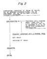
- Fig. 2 is a flow sheet of the production of a microcapsule type conductive filler
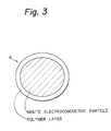
- Fig. 3 is a type diagram of the microcapsule type conductive filler
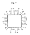
- Fig. 4 is a type diagram illustrating one example of a substrate
- Fig. 5 is a type diagram illustrating one example of a glass chip
- Fig. 6 is a type diagram illustrating sites for determination of electric continuity resistance and insulation resistance
- Fig. 1 is a graph showing the relation between insulation resistance and conductivity with the amount of minute conductive particles as a parameter
- Fig. 2 is a flow sheet of the production of a microcapsule type conductive filler
- Fig. 3 is a type diagram of the microcapsule type conductive filler
- Fig. 4 is a type diagram illustrating one example of a substrate
- Fig. 5 is a type diagram illustrating one example of a glass chip
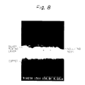
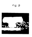
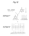
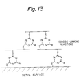
- FIG. 7 is a partially magnified diagram of Fig. 6, Fig. 8 is a photomicrograph of the microcapsule type conductive filler (15,000 magnifications), Fig. 9 is a photomicrograph of a part of union between a bump and a pad (504 magnifications), Fig. 10 is a type diagram illustrating the state of union between a chip and a substrate, Fig. 11 is a flow sheet of the production of a microcapsule type conductive filler as the second aspect of this invention, Fig. 12 is a type diagram illustrating a growth model of a triazine thiol film on the surface of metal, and Fig. 13 is a type diagram illustrating the reaction mechanism of an epoxy monomer with triazine thiol.
- a suspension is produced by dispersing minute conductive particles having the surface thereof treated with a coupling agent in a solution of a monomer and a reaction initiator (oil phase) and adding the resultant dispersion dropwise to water having an emulsifier and a viscosity enhancer dissolved therein (aqueous phase).
- the monomer is polymerized in situ on the surface of the minute conductive particles and allowed to form a coating thereon.
- the monomer that is usable singly herein are divinyl benzene and acryl.
- a thermosetting polymer is obtained from divinyl benzene monomer and a thermoplastic polymer from acryl monomer.
- a suspension is produced by dispersing minute conductive particles having the surface thereof treated with a coupling agent in the solution of a monomer in a solvent (oil phase) and adding the resultant dispersion dropwise to water having another monomer, an emulsifier, and a viscosity enhancer dissolved therein (aqueous phase).
- the monomers are interfacially polymerized on the surface of the minute conductive particles and allowed to coat the minute conductive particles.
- the coating can be alternatively effected by preparing a suspension having at least two kinds of monomers dissolved in the oil phase and subjecting the monomers to in situ polymerization.
- the monomers that are usable in the form of a combination of two monomers herein are epoxy/amine and bismaleimide/amine (both producing a thermosetting polymer).
- the minute conductive particles should be treated in advance with a coupling agent.
- the sp value of the coupling agent to be used for this treatment should be within ⁇ 10 (cal/cm3) 1 ⁇ 2 of that of the monomer to be used.
- the viscosity of the aqueous phase should be in the range between 20 and 10,000 cps.
- the suspension should be stirred at a rate in the range between 50 and 250 rpm to effect the reaction of the monomer.
- the reason for (1) is that since the monomolecular film of the coupling agent on the surface of the minute conductive particles and the monomer molecules are intertwined, the monomer is retained on the surface of the minute conductive particles and the coating is effected uniformly.
- the reason for (2) is that if the sp value deviates from the range of ⁇ 10 (cal/cm3) 1 ⁇ 2 , the monomer is not thoroughly intertwined with the coupling agent and it is retained on the surface of minute conductive particles with difficulty.
- the reason for (3) is that the minute conductive particles settle and agglomerate if the viscosity is less than 20 cps and the separation of the MC type conductive filler after completion of the coating is not obtained if the viscosity exceeds 10,000 cps.
- the reason for (4) is that the minute conductive particles settle and agglomerate during the reaction of the monomer if agitation is omitted.
- the minute conductive particles to be used for this method of production of the filler are only required to be made of a conductive metallic material.
- the kind of metallic material is irrespective.
- minute Cu particles having the surface thereof coated with Ag or minute Ag particles are preferably used.
- the minute conductive particles are preferably spheres or pseudospheres in shape. These minute conductive particles preferably have a diameter of not more than 50 ⁇ m.
- the insulating layer of a thermosetting resin for the MC type conductive filler is preferably made of a cured epoxy/amine or bismaleimide/amine type resin.
- the insulating layer of thermosetting resin of the MC type conductive filler preferably has a thickness of not more than 3 ⁇ m.
- This invention pertains in one aspect of an MC type conductive adhesive agent having dispersed in an adhesive agent the filler obtained as described above.
- the adhesive agent that can be effectively used in the MC type conductive adhesive agent is the same as mentioned above.
- an epoxy type one-component polyimide or polyester adhesive agent is preferably used.
- the viscosity of the adhesive agent mentioned above is preferably not more than 150,000 cps.
- the content of the MC type conductive filler in the MC type conductive adhesive agent is preferably not more than 50% by volume.
- One preferred embodiment of the method of this invention comprises forming a suspension by uniformly dispersing minute conductive particles allowing the presence of a solvent and a monomer (monomer A) on the surface thereof in water having another monomer (monomer B) dissolved therein and applying heat to the suspension thereby inducing the two monomers to react on the surface of the minute conductive particles and form an insulating polymer and consequently producing a microcapsule type filler.
- the monomer A and the monomer B are monomer components that are intended to form an insulating polymer.
- a polyamide is intended to form the insulating polymer
- adipic acid dichloride serves as the monomer A and hexamethylene diamine as the monomer B.
- polyurethane is intended to form the insulating polymer, for example, tetraethylene diisocyanate serves as the monomer A and methamethylene glycol as the monomer B.
- the solvents that are effectively usable for dissolving the monomer A include dichloroethane, chloroform, carbon tetrachloride, xylene, toluene, benzene, dichloromethane, and ethyl acetate, for example.
- the suspension is heated for the purpose of promoting the reaction of the monomers therein.
- the temperature of this heating is in the range between normal room temperature and boiling point of the solvent. It is selected in accordance with the particular quality of the suspension to be heated.
- the minute conductive particles must be treated with a coupling agent before using. This treatment serves the purpose of fixing the monomer A on the minute conductive particles.
- the viscosity of the aqueous phase having the monomer B dissolved therein is preferably adjusted so as to fall in the range between 20 and 10,000 cps by the addition of a viscosity enhancer.
- the suspension must be stirred at a rate in the range between 50 and 250 rpm for reacting the two monomers.
- the monomers are preferably used in an amount that is at least sufficient for the monomers to form a film of not less than 0.05 ⁇ m in thickness on the surface of the minute conductive particles.
- the affinity enhancer such as triazine thiol which is used at the step (a) in the method, i.e. the third aspect of this invention, allows effective polymerization of the monomers because it is capable of inducing uniform adhesion of the epoxy resin monomer to the surface of the minute metallic particles and opening the heterocycles in the resin. As a result, the heretofore difficult coating of the surface of the minute conductive particles with the thermosetting resin can be easily attained by the method of this invention.
- the coating film of the thermosetting resin is superior to the coating film of a thermoplastic resin in strength
- the MC type conductive filler can be incorporated in a large amount in the adhesive agent and the MC type conductive adhesive agent consequently produced can effect an adhesive union of two given members with higher reliability than the conventional technique.
- a microcapsule type conductive adhesive agent was produced with the following materials. Minute conductive particles: Minute pseudospheres of Cu having the surface thereof plated with Ag (Ag/Cu, average diameter 5 ⁇ m). Dispersant: Titanate type coupling agent. Monomers: Bisphenol A type epoxy (BPA) and tetraethylene pentamine (TEPA). Adhesive agent: Epoxy type one-component adhesive agent.
- a microcapsule type conductive filler was produced by faithfully following the procedure of Example 1, except that minute Ag particles (average diameter 0.1 ⁇ m) were used instead as minute conductive particles. It was evaluated in the same manner as in Example 1.
- Microcapsule type conductive filler and adhesive agent were produced by faithfully following the procedure of Example 1, except that 10 g of bismaleimide (BMI) and 0.1 g of diazobicycloundecene were used in place of the monomer BPA. They were evaluated in the same manner as in Example 1.
- a microcapsule type conductive filler was produced by faithfully following the procedure of Example, except that Cu particles 60 ⁇ m in diameter were used as minute conductive particles.
- microcapsule type conductive filler was evaluated in the same manner under the same conditions as described in (2) to (7) of Example 1.
- the produced filler having the surface thereof completely coated with a polymer showed insulation.
- the electric continuity resistance and the state of union between the bump and the pad were equal to those obtained in Example 1. No insulation was retained between the adjacent pads.
- a microcapsule type conductive filler produced by following the procedure of Example 1 was mixed with an epoxy type adhesive agent having a viscosity of 210,-000 cps.
- the filler could not be dispersed in the adhesive agent because the viscosity of the adhesive agent was unduly high.
- a microcapsule type conductive filler and a microcapsule type conductive adhesive agent were produced by faithfully following the procedure of Example 1, except that an oil phase obtained by dispersing 7 g of conductive particles treated with a coupling agent in 10 g of BPA in accordance with the flow sheet shown in Fig. 2 was used dichloroethane instead of ethyl acetate solvent in the oil phase. They were evaluated in the same manner as in Example 1.
- One kind of monomer was used and a thermosetting resin and a solvent were used, and one kind of monomer was used in the oil phase.
- a microcapsule type conductive filler and a microcapsule type conductive adhesive agent were produced by following the procedure of Example 1, except that an aqueous phase was prepared by dissolving 12 g of polyvinyl alcohol and 1.5 g of an emulsifier in 200 ml of water and a solution of 10 g of divinyl benzene and 0.1 g of benzoyl peroxide in 15 ml of ethyl acetate was used as an oil phase.
- Two kinds of monomers were used, including a thermosetting resin and a solvent, and two kinds of monomers were used in the oil phase.
- a microcapsule type conductive filler and a microcapsule type conductive adhesive agent were produced by following the procedure of Example 1, except that an aqueous phase was prepared by dissolving 12 g of polyvinyl alcohol and 1.5 g of an emulsifier in 200 ml of water and an oil phase was prepared with 15 ml of ethyl acetate and 5 g of imidazole. They were evaluated in the same manner as in Example 1.
- thermosetting resin Two kinds of monomers and a thermosetting resin were used only in the oil phase and no solvent was used.
- An MC filler and an MC conductive adhesive agent were produced by faithfully following the procedure of Example 6, except that the use of ethyl acetate was omitted. They were evaluated in the same manner as in Example 6.
- One kind of monomer and a thermosetting resin were used and no solvent was used.
- the monomer was used in the oil phase.
- a microcapsule type conductive filler and a microcapsule type conductive adhesive agent were produced by following the procedure of Example 2, except that an aqueous phase was prepared by dissolving 12 g of polyvinyl alcohol and an emulsifier in 200 ml of water and an oil phase was prepared by dispersing in 10 g of divinyl benzene 0.1 g of benzoyl peroxide and 7 g of minute conductive particles treated with a coupling agent in accordance with the flow sheet illustrated in Fig. 2 without using ethyl acetate (solvent). They were evaluated in the same manner as in Example 2.
- thermoplastic resin A blend of a thermoplastic resin and a thermosetting resin and a solvent were used.
- the monomer was used in the oil phase.
- a microcapsule type conductive filler and a microcapsule type conductive adhesive agent were produced by following the procedure of Example 1, except that 5 g of methyl methacrylate, 5 g of bismaleimide, and 0.1 g of azoisobutyronitrile were used as monomers in place of BPA and TEPA. They were evaluated in the same manner as in Example 1.
- thermoplastic resin A blend of a thermoplastic resin and a thermosetting resin and a solvent were used.
- the monomer was used in the oil phase and the aqueous phase.
- a microcapsule type conductive filler and a microcapsule type conductive adhesive agent were produced by following the procedure of Example 1, except that an aqueous solution was prepared by dissolving 12 g of polyvinyl alcohol, 1.5 g of an emulsifier, and 15 g of hexamethylene diamine in 200 ml of water and a solution of 7 g of adipic acid and 7 g of BPA in 15 ml of ethyl acetate was used as an oil phase. They were evaluated in the same manner as in Example 1.
- a blend of monomers was used in the oil phase and no solvent was used.
- An MC filler and an MC type conductive adhesive agent were produced by following the procedure of Example 10, except that ethyl acetate was omitted. They were evaluated in the same manner as Example 10.
- a blend of monomers was used in the oil phase and the aqueous phase and no solvent was used.
- An MC type filler and an MC type conductive adhesive agent were produced by following the procedure of Example 11, except that ethyl acetate was omitted. They were evaluated in the same manner as in Example 11.
- Example 1 An MC type filler produced by the procedure of Example 1 was tested for the following items.
- Table 4 shows the results of the test performed on MC fillers prepared using coupling agents of different sp values with respect to electric continuity.
- Table 4 Results of test of MC type filler for insulation Difference of sp values of coupling agent and monomer Results of test for insulation 0 Insulation 5 Insulation 10 Insulation 11 Electric continuity
- the results indicate that the difference between the sp value of the monomer (epoxy resin) and the sp value of the coupling agent must be within 10 (cal/cm3) 1 ⁇ 2 .
- Table 5 Relation between viscosity of aqueous phase and suspension Viscosity of aqueous phase (cps) 10 20 100 1000 10000 11,000 Stability of suspension Sedimentation of minute conductive particles observed Stable Stable Stable Stable Suspension not producible and separation of MC filler after reaction not effectible The results indicate that the viscosity of the aqueous solution is proper in the range between 20 and 10,000 cps.
- (3) Effect of stirring speed on stability of suspension Table 6 shows the results of the test performed involving the effect of the stirring speed (30, 50, 250, and 300 rpm) on the stability of the suspension.
- Table 6 Relation of speed of stirring and stability of suspension Speed of stirring 30 50 250 300 Stability of suspension Sedimentation of minute conductive particles observed Stable Stable Adhesion of minute conductive particles to beaker wall observed The results indicate that the stirring must be carried out at a rate in a range between 50 and 250 rpm.
- Table 7 shows the results of the test performed on minute conductive particles of diameters 10, 30, 50, and 70 ⁇ m for insulation. Table 7 Relation between particle diameter and insulating property of coated minute conductive particles Particle diameter ( ⁇ m) of minute conductive particles Results of test for insulation 10 Insulation 30 Insulation 50 Insulation 70 Electric continuity The results indicate that the minute conductive particles to be used should have a diameter of not more than 50 ⁇ m.
- Table 9 shows the results of the test performed on insulating resin layers formed of the MC type conductive filler with different thicknesses with respect to electric continuity.
- Table 9 Relation between thickness and conductivity of insulating resin Thickness ( ⁇ m) of insulating resin Resistance per site of measurement ( ⁇ ) 0.1 0.1 2.0 0.4 3.0 0.5 4.0 1.5 It is noted from Table 9 that the resistance to electric continuity was high and points of poor electric continuity were detected when the thickness of the insulating resin layer (coating layer) was 4.0 ⁇ m.
- the results indicate that the thickness of the insulating resin layer is desired to be not more than 3 ⁇ m.
- Table 10 shows the relation between the MC type filler and the state of curing of the adhesive agent.
- An MC type conductive adhesive agent was produced with the following materials. Minute conductive particles: Minute Cu pseudospheres having the surface plated with Ag (Ag/Cu, average particle diameter 5 ⁇ m).
- Adhesive agent A composition consisting of an epoxy resin as the main component and an acid anhydride as the curing agent).
- Affinity agent Triazine thiol (RTD).
- Monomer Bisphenol A type epoxy resin (BPA) (produced by Shell and marketed under trademark designation of "Epikote 828").
- Example 14 In the production of capsule type minute metallic particles by the procedure of Example 14, the stirring of the suspension was carried out at varying rates of 30, 50, 250, and 300 rpm to determine the effect of the stirring speed on the stability of the suspension.
- Table 11 shows the effect of the stirring speed (30, 50, 250, and 300 rpm) on the stability of the suspension. The results indicate that the stirring speed must be in the range between 50 and 250 rpm for the sake of suspension stability. Table 11 Relation between stirring speed and suspension stability Speed of stirring (rpm) 30 50 250 300 Suspension stability Sedimentation of minute conductive particles observed Stable Stable Adhesion of minute conductive particles to beaker wall observed
- An MC type conductive filler and a capsule type conductive adhesive agent were produced by following the procedure of Example 14, except that alcohol was used in the place of acetone. They were evaluated in the same manner as in Example 14.
- This invention is constructed as described above, it enables an MC type conductive filler coated with a thermosetting resin possessed of better characteristic properties than a thermoplastic resin to be produced easily at a low cost.
- this invention realizes a practical MC type conductive adhesive agent excellent in reliability and performance.
Landscapes
- Physics & Mathematics (AREA)
- Chemical & Material Sciences (AREA)
- Dispersion Chemistry (AREA)
- Spectroscopy & Molecular Physics (AREA)
- Adhesives Or Adhesive Processes (AREA)
- Conductive Materials (AREA)
- Pigments, Carbon Blacks, Or Wood Stains (AREA)
- Paints Or Removers (AREA)
- Manufacturing Of Micro-Capsules (AREA)
Priority Applications (1)
| Application Number | Priority Date | Filing Date | Title |
|---|---|---|---|
| EP97103551A EP0783177B1 (fr) | 1991-10-24 | 1992-10-23 | Adhésif conducteur et procédé de production d'une matière de charge conductrice de type microcapsule pour l'adhésif conducteur |
Applications Claiming Priority (4)
| Application Number | Priority Date | Filing Date | Title |
|---|---|---|---|
| JP303818/91 | 1991-10-24 | ||
| JP30381891 | 1991-10-24 | ||
| JP4263219A JPH082995B2 (ja) | 1991-10-24 | 1992-09-04 | マイクロカプセル型導電性フィラーの作製方法 |
| JP263219/92 | 1992-09-04 |
Related Child Applications (2)
| Application Number | Title | Priority Date | Filing Date |
|---|---|---|---|
| EP97103551A Division EP0783177B1 (fr) | 1991-10-24 | 1992-10-23 | Adhésif conducteur et procédé de production d'une matière de charge conductrice de type microcapsule pour l'adhésif conducteur |
| EP97103551.4 Division-Into | 1997-03-03 |
Publications (3)
| Publication Number | Publication Date |
|---|---|
| EP0539211A2 true EP0539211A2 (fr) | 1993-04-28 |
| EP0539211A3 EP0539211A3 (fr) | 1994-03-16 |
| EP0539211B1 EP0539211B1 (fr) | 1997-10-01 |
Family
ID=26545912
Family Applications (1)
| Application Number | Title | Priority Date | Filing Date |
|---|---|---|---|
| EP92309717A Expired - Lifetime EP0539211B1 (fr) | 1991-10-24 | 1992-10-23 | Procédé de fabrication d'un matériau de remplissage conducteur du type à microcapsule |
Country Status (3)
| Country | Link |
|---|---|
| EP (1) | EP0539211B1 (fr) |
| CA (1) | CA2081222C (fr) |
| DE (2) | DE69222501T2 (fr) |
Cited By (6)
| Publication number | Priority date | Publication date | Assignee | Title |
|---|---|---|---|---|
| WO2000074132A1 (fr) * | 1999-06-01 | 2000-12-07 | Alpha Metals, Inc. | Procede de revetement de protection de spheres d'alliage de brasage a grille matricielle a billes |
| US6255138B1 (en) | 1997-06-23 | 2001-07-03 | Three Bond Co., Ltd. | Process for producing microencapsulated electroconductive filler |
| EP1093160A3 (fr) * | 1999-10-12 | 2001-12-05 | Sony Chemicals Corporation | Matériau de connexion pour connexion par conducteur électrique anisotrope |
| EP1335389A4 (fr) * | 2000-10-23 | 2006-08-02 | Sekisui Chemical Co Ltd | Particule enrobee |
| CN105295760A (zh) * | 2015-10-23 | 2016-02-03 | 浙江欧仁新材料有限公司 | 一种各向异性导电双面胶 |
| CN111129789A (zh) * | 2018-10-31 | 2020-05-08 | 北京梦之墨科技有限公司 | 一种可变电路及电子器件 |
Families Citing this family (1)
| Publication number | Priority date | Publication date | Assignee | Title |
|---|---|---|---|---|
| US6734466B2 (en) * | 2002-03-05 | 2004-05-11 | Agilent Technologies, Inc. | Coated phosphor filler and a method of forming the coated phosphor filler |
Family Cites Families (4)
| Publication number | Priority date | Publication date | Assignee | Title |
|---|---|---|---|---|
| JPH02103874A (ja) * | 1988-10-11 | 1990-04-16 | Stanley Electric Co Ltd | 異方性導電膜 |
| JPH02103875A (ja) * | 1988-10-11 | 1990-04-16 | Stanley Electric Co Ltd | 異方性導電材 |
| JP2906612B2 (ja) * | 1990-08-10 | 1999-06-21 | 富士通株式会社 | マイクロカプセル型導電性接着剤と接着方法 |
| JP3092971B2 (ja) * | 1991-06-07 | 2000-09-25 | 富士通株式会社 | 金属微粒子のポリマ被覆方法 |
-
1992
- 1992-10-23 DE DE69222501T patent/DE69222501T2/de not_active Expired - Lifetime
- 1992-10-23 EP EP92309717A patent/EP0539211B1/fr not_active Expired - Lifetime
- 1992-10-23 CA CA002081222A patent/CA2081222C/fr not_active Expired - Lifetime
- 1992-10-23 DE DE69232886T patent/DE69232886T2/de not_active Expired - Lifetime
Cited By (10)
| Publication number | Priority date | Publication date | Assignee | Title |
|---|---|---|---|---|
| US6255138B1 (en) | 1997-06-23 | 2001-07-03 | Three Bond Co., Ltd. | Process for producing microencapsulated electroconductive filler |
| WO2000074132A1 (fr) * | 1999-06-01 | 2000-12-07 | Alpha Metals, Inc. | Procede de revetement de protection de spheres d'alliage de brasage a grille matricielle a billes |
| US6506448B1 (en) | 1999-06-01 | 2003-01-14 | Fry's Metals, Inc. | Method of protective coating BGA solder alloy spheres |
| EP1093160A3 (fr) * | 1999-10-12 | 2001-12-05 | Sony Chemicals Corporation | Matériau de connexion pour connexion par conducteur électrique anisotrope |
| US6451875B1 (en) | 1999-10-12 | 2002-09-17 | Sony Chemicals Corporation | Connecting material for anisotropically electroconductive connection |
| EP1335389A4 (fr) * | 2000-10-23 | 2006-08-02 | Sekisui Chemical Co Ltd | Particule enrobee |
| US7252883B2 (en) | 2000-10-23 | 2007-08-07 | Sekisui Chemical Co., Ltd. | Coated particles |
| KR100832282B1 (ko) * | 2000-10-23 | 2008-05-26 | 세키스이가가쿠 고교가부시키가이샤 | 피복 입자 |
| CN105295760A (zh) * | 2015-10-23 | 2016-02-03 | 浙江欧仁新材料有限公司 | 一种各向异性导电双面胶 |
| CN111129789A (zh) * | 2018-10-31 | 2020-05-08 | 北京梦之墨科技有限公司 | 一种可变电路及电子器件 |
Also Published As
| Publication number | Publication date |
|---|---|
| CA2081222A1 (fr) | 1993-04-25 |
| CA2081222C (fr) | 1998-10-27 |
| DE69222501T2 (de) | 1998-02-05 |
| EP0539211A3 (fr) | 1994-03-16 |
| DE69232886D1 (de) | 2003-02-06 |
| DE69222501D1 (de) | 1997-11-06 |
| EP0539211B1 (fr) | 1997-10-01 |
| DE69232886T2 (de) | 2005-03-10 |
Similar Documents
| Publication | Publication Date | Title |
|---|---|---|
| US6080443A (en) | Method for production of microcapsule type conductive filler | |
| US5120665A (en) | Method of using an anisotropically electroconductive adhesive having pressure-deformable electroconductive particles to electrically connect circuits | |
| US5641996A (en) | Semiconductor unit package, semiconductor unit packaging method, and encapsulant for use in semiconductor unit packaging | |
| US6020059A (en) | Multilayer anisotropic electroconductive adhesive and method for manufacturing same | |
| KR100710103B1 (ko) | 피복 도전성 미립자, 피복 도전성 미립자의 제조방법,이방성 도전재료, 및 도전 접속 구조체 | |
| EP0554396A1 (fr) | Formulation adhesive a durcissement rapide pour dispositif a semi-conducteurs | |
| JP5044880B2 (ja) | 樹脂組成物、これを用いた回路部材接続用接着剤及び回路板 | |
| JP3455871B2 (ja) | マイクロカプセル型導電性フィラーの製造方法 | |
| CA2081222C (fr) | Methode d'enduction de charge conductrice sous microcapsules | |
| JP2983816B2 (ja) | 導電性樹脂ペースト | |
| WO2004100179A1 (fr) | Globule conducteur isole pour connexion conductive anisotrope, son procede de preparation et produit utilisant le globule | |
| US6406746B1 (en) | Microcapsulating conductive metal particles with polymerized monomers | |
| JP4128281B2 (ja) | エポキシ系樹脂組成物 | |
| JP2970720B2 (ja) | マイクロカプセル型導電性接着剤及びその製造方法 | |
| CA2189801C (fr) | Methode de production de particules de bourrage conductrices de type microcapsulaire | |
| JPH02288019A (ja) | 異方性導電フィルム | |
| JPH0688040A (ja) | マイクロカプセル型導電性フィラーの作製方法 | |
| Paik et al. | New anisotropic conductive adhesives for low cost and reliable flip chip on organic substrates applications | |
| Paik et al. | Flip chip assembly on organic boards using anisotropic conductive adhesives (ACAs) and nickel/gold bumps | |
| JPH08253745A (ja) | 接着剤 | |
| JP4092790B2 (ja) | 回路板 | |
| JPH01121385A (ja) | 電子部品接合用接着フィルム | |
| JPH02269174A (ja) | 導電性接着剤 | |
| JPH06275123A (ja) | カプセル型導電性接着剤用導電性フィラー | |
| JPH01231208A (ja) | 導電性ペースト |
Legal Events
| Date | Code | Title | Description |
|---|---|---|---|
| PUAI | Public reference made under article 153(3) epc to a published international application that has entered the european phase |
Free format text: ORIGINAL CODE: 0009012 |
|
| AK | Designated contracting states |
Kind code of ref document: A2 Designated state(s): DE FR GB |
|
| PUAL | Search report despatched |
Free format text: ORIGINAL CODE: 0009013 |
|
| AK | Designated contracting states |
Kind code of ref document: A3 Designated state(s): DE FR GB |
|
| 17P | Request for examination filed |
Effective date: 19940913 |
|
| 17Q | First examination report despatched |
Effective date: 19951205 |
|
| GRAG | Despatch of communication of intention to grant |
Free format text: ORIGINAL CODE: EPIDOS AGRA |
|
| GRAH | Despatch of communication of intention to grant a patent |
Free format text: ORIGINAL CODE: EPIDOS IGRA |
|
| GRAH | Despatch of communication of intention to grant a patent |
Free format text: ORIGINAL CODE: EPIDOS IGRA |
|
| GRAA | (expected) grant |
Free format text: ORIGINAL CODE: 0009210 |
|
| AK | Designated contracting states |
Kind code of ref document: B1 Designated state(s): DE FR GB |
|
| XX | Miscellaneous (additional remarks) |
Free format text: TEILANMELDUNG 97103551.4 EINGEREICHT AM 03/03/97. |
|
| REF | Corresponds to: |
Ref document number: 69222501 Country of ref document: DE Date of ref document: 19971106 |
|
| ET | Fr: translation filed | ||
| PLBE | No opposition filed within time limit |
Free format text: ORIGINAL CODE: 0009261 |
|
| 26N | No opposition filed | ||
| REG | Reference to a national code |
Ref country code: GB Ref legal event code: IF02 |
|
| PGFP | Annual fee paid to national office [announced via postgrant information from national office to epo] |
Ref country code: DE Payment date: 20101020 Year of fee payment: 19 |
|
| PGFP | Annual fee paid to national office [announced via postgrant information from national office to epo] |
Ref country code: GB Payment date: 20101020 Year of fee payment: 19 |
|
| PGFP | Annual fee paid to national office [announced via postgrant information from national office to epo] |
Ref country code: FR Payment date: 20111103 Year of fee payment: 20 |
|
| REG | Reference to a national code |
Ref country code: DE Ref legal event code: R071 Ref document number: 69222501 Country of ref document: DE |
|
| REG | Reference to a national code |
Ref country code: DE Ref legal event code: R071 Ref document number: 69222501 Country of ref document: DE |
|
| REG | Reference to a national code |
Ref country code: GB Ref legal event code: PE20 Expiry date: 20121022 |
|
| PG25 | Lapsed in a contracting state [announced via postgrant information from national office to epo] |
Ref country code: GB Free format text: LAPSE BECAUSE OF EXPIRATION OF PROTECTION Effective date: 20121022 |