EP0590794A2 - Dispositif d'accouplement pour un compresseur - Google Patents
Dispositif d'accouplement pour un compresseur Download PDFInfo
- Publication number
- EP0590794A2 EP0590794A2 EP93306813A EP93306813A EP0590794A2 EP 0590794 A2 EP0590794 A2 EP 0590794A2 EP 93306813 A EP93306813 A EP 93306813A EP 93306813 A EP93306813 A EP 93306813A EP 0590794 A2 EP0590794 A2 EP 0590794A2
- Authority
- EP
- European Patent Office
- Prior art keywords
- pulley
- armature
- plate
- coupling mechanism
- circumference
- Prior art date
- Legal status (The legal status is an assumption and is not a legal conclusion. Google has not performed a legal analysis and makes no representation as to the accuracy of the status listed.)
- Granted
Links
- 230000008878 coupling Effects 0.000 title claims abstract description 80
- 238000010168 coupling process Methods 0.000 title claims abstract description 80
- 238000005859 coupling reaction Methods 0.000 title claims abstract description 80
- 230000007246 mechanism Effects 0.000 title claims abstract description 65
- 230000002093 peripheral effect Effects 0.000 claims description 7
- 230000006872 improvement Effects 0.000 claims description 4
- 230000015556 catabolic process Effects 0.000 claims 1
- 230000007257 malfunction Effects 0.000 description 12
- 238000004378 air conditioning Methods 0.000 description 8
- 239000000463 material Substances 0.000 description 6
- 230000008859 change Effects 0.000 description 3
- 238000005219 brazing Methods 0.000 description 2
- 238000010276 construction Methods 0.000 description 2
- 238000001816 cooling Methods 0.000 description 2
- 239000013013 elastic material Substances 0.000 description 2
- 238000003466 welding Methods 0.000 description 2
- 230000005540 biological transmission Effects 0.000 description 1
- 230000001419 dependent effect Effects 0.000 description 1
- 238000006073 displacement reaction Methods 0.000 description 1
- 230000005489 elastic deformation Effects 0.000 description 1
- 230000003993 interaction Effects 0.000 description 1
- 238000004519 manufacturing process Methods 0.000 description 1
- 239000002184 metal Substances 0.000 description 1
- 229910052751 metal Inorganic materials 0.000 description 1
- 150000002739 metals Chemical class 0.000 description 1
- 239000003507 refrigerant Substances 0.000 description 1
- 238000005057 refrigeration Methods 0.000 description 1
- 230000004044 response Effects 0.000 description 1
- 229920003002 synthetic resin Polymers 0.000 description 1
- 239000000057 synthetic resin Substances 0.000 description 1
Images


Classifications
-
- F—MECHANICAL ENGINEERING; LIGHTING; HEATING; WEAPONS; BLASTING
- F04—POSITIVE - DISPLACEMENT MACHINES FOR LIQUIDS; PUMPS FOR LIQUIDS OR ELASTIC FLUIDS
- F04B—POSITIVE-DISPLACEMENT MACHINES FOR LIQUIDS; PUMPS
- F04B49/00—Control, e.g. of pump delivery, or pump pressure of, or safety measures for, machines, pumps, or pumping installations, not otherwise provided for, or of interest apart from, groups F04B1/00 - F04B47/00
-
- F—MECHANICAL ENGINEERING; LIGHTING; HEATING; WEAPONS; BLASTING
- F16—ENGINEERING ELEMENTS AND UNITS; GENERAL MEASURES FOR PRODUCING AND MAINTAINING EFFECTIVE FUNCTIONING OF MACHINES OR INSTALLATIONS; THERMAL INSULATION IN GENERAL
- F16D—COUPLINGS FOR TRANSMITTING ROTATION; CLUTCHES; BRAKES
- F16D9/00—Couplings with safety member for disconnecting, e.g. breaking or melting member
- F16D9/06—Couplings with safety member for disconnecting, e.g. breaking or melting member by breaking due to shear stress
Definitions
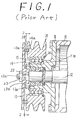
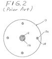
- a plurality of cylindrical members 28 are disposed between the inner axial surface, with respect to housing 10, of armature 13 and the outer axial surface, also with respect to housing 10, of pulley 14 to couple armature 13 to pulley 14. Holes 13a are formed on the inner axial surface of armature 13, and one end of each cylindrical member 28 is disposed therein. The other end of each cylindrical member 28 is disposed in corresponding hole 14a formed on the outer axial surface of pulley 14. Cylindrical members 28 may be made of synthetic resins or metals which are easily broken if a large torque acts between pulley 14 and armature 13, i.e. , a sufficiently large force which acts to rotate pulley 14 with respect to armature 13.
- pulley 14 is disconnected from armature 13 and is free to rotate without resistance applied through armature 13 from motionless drive shaft 12.
- the maximum acceptable amount of torque and consequently, the size, material, and number of cylindrical members 28 is dependent on the air conditioning system and the compressor with which the coupling mechanism is used.
- first portions of the plate members may be located on a first circular plane which is parallel to the axial suffice of the pulley.
- the second portions of the plate members may be located on a second circular plane which is parallel to the axial surface of the pulley.
- the first portions of the plate members are positioned with respect to the second portions of the plate members, so that the material of each plate member will be elastically deformed, and the first plane is axially offset from the second circular plane. Therefore, if the compressor fails or malfunctions and the drive shaft stops rotating damage to engine or the driving system is avoided because the torque applied by the pulley causes the breakaway portions to release the plate members from the pulley and to disconnect the armature plate from the pulley, so that each may rotate without contacting or biting the other.
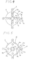
- Coupling plate member 7 which is rectangular in shape, divides plate member 7 into an inner plate portion 7a having a plurality of holes 7f, e.g. , two holes 7f, a center plate portion 7c in the center of plate member 7, and outer plate portion 7b having at least one hole 7e.
- Center plate portion 7c is formed between inner plate portion 7a and outer plate portion 7b and includes a notched or breakaway portion 7d which is partly cut-out from plate member 7.
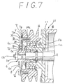
- plate members 7 are also secured to pulley 14 at regular angular intervals of 90° around the circumference of pulley 14 and around a radial surface of drive shaft 12, so that bolts 30 pass through washer 9 and holes 7e of each plate member 7.
- Bolts 30 screw into holes 14a of pulley 14, and outer plate portions 7b are axially offset from inner plate portion 7a.
- Center plate portions 7c are inclined toward pulley 14, thereby elastically deforming the material for plate member 7. If a distance L extends between the axial inner surface of plate member 7 which is secured to armature plate 6b by rivets 8 and the axial outer surface of plate member 7 which secured to pulley 14 by bolts 10, distance L must be greater than zero.
- plate member 7 and pulley 14 and armature 6 may not be provided with any holes for connecting by bolts 30 or rivets 8. Instead, armature 6 may be connected to pulley 14 through plate member 7 by means of brazing, spot welding or the like.
Landscapes
- Engineering & Computer Science (AREA)
- General Engineering & Computer Science (AREA)
- Mechanical Engineering (AREA)
- Compressors, Vaccum Pumps And Other Relevant Systems (AREA)
- Pulleys (AREA)
- Structures Of Non-Positive Displacement Pumps (AREA)
- Transmission Devices (AREA)
- Auxiliary Drives, Propulsion Controls, And Safety Devices (AREA)
Applications Claiming Priority (3)
| Application Number | Priority Date | Filing Date | Title |
|---|---|---|---|
| JP6724892 | 1992-09-02 | ||
| JP67248/92 | 1992-09-02 | ||
| JP1992067248U JP2575892Y2 (ja) | 1992-09-02 | 1992-09-02 | プーリー直結型コンプレッサー |
Publications (3)
| Publication Number | Publication Date |
|---|---|
| EP0590794A2 true EP0590794A2 (fr) | 1994-04-06 |
| EP0590794A3 EP0590794A3 (fr) | 1994-04-27 |
| EP0590794B1 EP0590794B1 (fr) | 1999-10-13 |
Family
ID=13339437
Family Applications (1)
| Application Number | Title | Priority Date | Filing Date |
|---|---|---|---|
| EP93306813A Expired - Lifetime EP0590794B1 (fr) | 1992-09-02 | 1993-08-27 | Ensemble d'un dispositif d'accouplement avec un compresseur |
Country Status (8)
| Country | Link |
|---|---|
| US (1) | US5443372A (fr) |
| EP (1) | EP0590794B1 (fr) |
| JP (1) | JP2575892Y2 (fr) |
| KR (1) | KR100218657B1 (fr) |
| AU (1) | AU666031B2 (fr) |
| CA (1) | CA2105350C (fr) |
| DE (1) | DE69326737T2 (fr) |
| SG (1) | SG48778A1 (fr) |
Cited By (6)
| Publication number | Priority date | Publication date | Assignee | Title |
|---|---|---|---|---|
| EP0702167A1 (fr) * | 1994-09-14 | 1996-03-20 | Nippondenso Co., Ltd. | Dispositif de transmission de puissance rotative |
| US5899811A (en) * | 1996-02-29 | 1999-05-04 | Denso Corporation | Device for transmitting rotational power |
| DE10354049A1 (de) * | 2003-11-19 | 2005-06-30 | Winkelmann Palsis Motortechnik Gmbh & Co.Kg | Vorrichtung zur Übertragung eines Drehmomentes von einem Verbrennungsmotor zu einem Nebenaggregat |
| EP1577587A2 (fr) | 2004-03-18 | 2005-09-21 | Halla Climate Control Corporation | Dispositif de transmission de force pour un compresseur sans embrayage |
| DE19919449B4 (de) * | 1998-05-04 | 2015-10-15 | Schaeffler Technologies AG & Co. KG | Triebscheibe |
| WO2017046490A1 (fr) * | 2015-09-17 | 2017-03-23 | Safran Electrical & Power | Ventilateur rotativement connecté à un arbre moteur par l'intermédiaire d'un élément fusible |
Families Citing this family (27)
| Publication number | Priority date | Publication date | Assignee | Title |
|---|---|---|---|---|
| JPH08319945A (ja) * | 1995-05-25 | 1996-12-03 | Zexel Corp | クラッチレス圧縮機 |
| US5715662A (en) * | 1995-11-17 | 1998-02-10 | Deere & Company | Drive shear device for rotary cutter unit |
| US5826991A (en) * | 1996-01-19 | 1998-10-27 | Interbold | Printer apparatus for automated banking machine |
| JPH10259830A (ja) * | 1997-03-21 | 1998-09-29 | Toyota Autom Loom Works Ltd | 動力伝達構造 |
| JP2000170870A (ja) * | 1998-12-04 | 2000-06-23 | Toyota Autom Loom Works Ltd | 動力伝達機構 |
| DE10066236B4 (de) * | 1999-06-21 | 2016-12-15 | Denso Corporation | Umlauf-Übertragungsvorrichtung mit Drehmoment-Begrenzungseinrichtung |
| US6520684B2 (en) | 2001-03-29 | 2003-02-18 | International Engine Intellectual Property Company, L.L.C. | Bearing retention system |
| JP2002349596A (ja) * | 2001-05-22 | 2002-12-04 | Denso Corp | トルク伝達装置 |
| JP2003035255A (ja) * | 2001-07-23 | 2003-02-07 | Toyota Industries Corp | 動力伝達部材の締結構造 |
| FR2846387A1 (fr) * | 2002-10-24 | 2004-04-30 | Littoral Prec | Limiteur de couple. |
| DE102004002668A1 (de) * | 2004-01-18 | 2005-09-22 | Bakelite Ag | Vorrichtung zur Übertragung eines Drehmomentes von einem Motor zu einem Kompressor |
| JP4464730B2 (ja) * | 2004-04-05 | 2010-05-19 | カルソニックカンセイ株式会社 | プーリおよびこれを用いた動力伝達装置 |
| JP2005315387A (ja) * | 2004-04-30 | 2005-11-10 | Sanden Corp | 動力伝達装置 |
| US20060021316A1 (en) * | 2004-07-28 | 2006-02-02 | Harkcom Melanie W | Disc cutterbar shear device |
| DE102004056487B4 (de) * | 2004-11-23 | 2006-10-19 | Winkelmann Powertrain Components Gmbh & Co. Kg | Mitnehmerscheibe |
| KR101156772B1 (ko) * | 2006-09-26 | 2012-06-18 | 한라공조주식회사 | 압축기의 동력전달구조 |
| FR2916027B1 (fr) * | 2007-05-09 | 2009-11-06 | Skf Ab | Dispositif de transmission de couple. |
| US8371947B2 (en) * | 2007-06-01 | 2013-02-12 | Halla Climate Control Corp. | Power transmission device of clutchless compressor |
| FR2946716B1 (fr) * | 2009-06-12 | 2011-07-08 | Skf Ab | Dispositif de poulie a anneau elastique premonte et procede de montage du dispositif. |
| US8753237B2 (en) * | 2011-03-17 | 2014-06-17 | Honda Motor Co., Ltd. | Alternator with decoupling device |
| US8517698B2 (en) | 2011-03-17 | 2013-08-27 | Delphi Technologies, Inc. | Air conditioning compressor over-torque protector |
| JP2012225488A (ja) * | 2011-04-22 | 2012-11-15 | Toyota Industries Corp | トルク伝達機構 |
| KR101282270B1 (ko) * | 2011-04-26 | 2013-07-10 | 주식회사 지엔원 | 코일리스 클러치의 동력전달 차단장치 |
| US9371835B2 (en) | 2013-07-19 | 2016-06-21 | Praxair Technology, Inc. | Coupling for directly driven compressor |
| US10717518B2 (en) * | 2018-02-21 | 2020-07-21 | Garmin International, Inc. | Aviation actuator assembly with mechanical fuse |
| US11203842B2 (en) * | 2019-10-10 | 2021-12-21 | Caterpillar Paving Products Inc. | Torque limiting device for road milling machine |
| EP4074596B1 (fr) * | 2021-04-12 | 2023-05-31 | Ratier-Figeac SAS | Disque de frein avec fusible thermique intégré et procédé de fabrication d'un disque de frein avec fusible thermique intégré |
Family Cites Families (31)
| Publication number | Priority date | Publication date | Assignee | Title |
|---|---|---|---|---|
| US490313A (en) * | 1893-01-24 | Carl schlickeysen | ||
| US1326869A (en) * | 1919-12-30 | Elastic-fluid turbine | ||
| DE7524954U (de) * | 1976-11-04 | Atec Weiss Kg, 4044 Kaarst | Kupplung für zwei im wesentlichen fluchtende Wellen mit einer überlastsicherung zum Begrenzen des Drehmoments | |
| US1343152A (en) * | 1919-06-14 | 1920-06-08 | William C Olson | Pulley attachment for motors |
| US1498281A (en) * | 1923-12-01 | 1924-06-17 | Jones Stanley | Overload release coupling |
| GB888116A (en) * | 1958-09-26 | 1962-01-24 | Gaetano Thomas Trigilio | Drive mechanism |
| US2892329A (en) * | 1958-09-26 | 1959-06-30 | Gaetano T Trigilio | Drive mechanism |
| US3071945A (en) * | 1961-06-26 | 1963-01-08 | Ernest S Shomo | Shear key |
| US3472046A (en) * | 1967-11-01 | 1969-10-14 | Allis Chalmers Mfg Co | Torque limiting safety device |
| US3662619A (en) * | 1970-08-26 | 1972-05-16 | Gen Electric | Fail-safe rotary machine |
| US3861829A (en) * | 1973-04-04 | 1975-01-21 | Borg Warner | Variable capacity wobble plate compressor |
| JPS539670B2 (fr) * | 1975-02-14 | 1978-04-07 | ||
| DE2640989C2 (de) * | 1976-09-11 | 1978-08-10 | Atec Weiss Kg, 4044 Kaarst | Kupplung mit Überlastsicherung |
| SU713540A3 (ru) * | 1976-12-18 | 1980-01-30 | Тиссен Индустри Аг (Фирма) | Крутильно-упруга муфта и способ ее изготовлени |
| DE2729041A1 (de) * | 1977-06-28 | 1979-01-11 | Johann Hochreuter | Brechleistensicherheitskupplung |
| EP0013175B1 (fr) * | 1978-12-25 | 1983-06-22 | Sanden Corporation | Embrayage électromagnétique |
| US4624354A (en) * | 1980-11-10 | 1986-11-25 | Sanden Corporation | Electromagnetic clutch |
| DE3043744C2 (de) * | 1980-11-20 | 1982-11-25 | A. Friedr. Flender Gmbh & Co Kg, 4290 Bocholt | Verfahren zur Verringerung der Abschaltspanne bei Überlast und eine Sicherheitskupplung zur Durchführung des Verfahrens |
| JPS5924538U (ja) * | 1982-08-09 | 1984-02-15 | サンデン株式会社 | 電磁クラツチ |
| US4616742A (en) * | 1983-03-30 | 1986-10-14 | Sanden Corporation | Spring coupling for an electromagnetic clutch |
| JPS6045934U (ja) * | 1983-09-05 | 1985-04-01 | サンデン株式会社 | 電磁スプリングクラッチ |
| DE3366576D1 (en) * | 1983-06-18 | 1986-11-06 | Vickers Systems Gmbh | Double pump |
| JPS6045935U (ja) * | 1983-09-05 | 1985-04-01 | サンデン株式会社 | 電磁スプリングクラッチ |
| US4694945A (en) * | 1984-10-16 | 1987-09-22 | Sanden Corporation | Electromagnetic clutch with an improved magnetic rotatable member |
| JPS62158226U (fr) * | 1986-03-28 | 1987-10-07 | ||
| JPS6323031A (ja) * | 1986-07-14 | 1988-01-30 | Sanden Corp | 電磁クラツチ |
| JPH0639105Y2 (ja) * | 1986-07-23 | 1994-10-12 | サンデン株式会社 | プ−リ−直結型コンプレッサ− |
| JPH0538250Y2 (fr) * | 1986-10-06 | 1993-09-28 | ||
| JPS63308229A (ja) * | 1987-06-05 | 1988-12-15 | Sanden Corp | クラッチロ−タの構造 |
| JPH01136727U (fr) * | 1988-03-15 | 1989-09-19 | ||
| US4932280A (en) * | 1988-11-03 | 1990-06-12 | Sundstrand Corporation | Coaxial drive shaft system with shearable section |
-
1992
- 1992-09-02 JP JP1992067248U patent/JP2575892Y2/ja not_active Expired - Lifetime
-
1993
- 1993-08-24 AU AU44817/93A patent/AU666031B2/en not_active Ceased
- 1993-08-27 DE DE69326737T patent/DE69326737T2/de not_active Expired - Fee Related
- 1993-08-27 EP EP93306813A patent/EP0590794B1/fr not_active Expired - Lifetime
- 1993-08-27 SG SG1996001586A patent/SG48778A1/en unknown
- 1993-09-01 CA CA002105350A patent/CA2105350C/fr not_active Expired - Fee Related
- 1993-09-01 US US08/114,188 patent/US5443372A/en not_active Expired - Lifetime
- 1993-09-02 KR KR1019930017452A patent/KR100218657B1/ko not_active Expired - Fee Related
Cited By (9)
| Publication number | Priority date | Publication date | Assignee | Title |
|---|---|---|---|---|
| EP0702167A1 (fr) * | 1994-09-14 | 1996-03-20 | Nippondenso Co., Ltd. | Dispositif de transmission de puissance rotative |
| US5683299A (en) * | 1994-09-14 | 1997-11-04 | Nippondenso Co., Ltd. | Device for transmitting rotational power |
| US5899811A (en) * | 1996-02-29 | 1999-05-04 | Denso Corporation | Device for transmitting rotational power |
| DE19919449B4 (de) * | 1998-05-04 | 2015-10-15 | Schaeffler Technologies AG & Co. KG | Triebscheibe |
| DE10354049A1 (de) * | 2003-11-19 | 2005-06-30 | Winkelmann Palsis Motortechnik Gmbh & Co.Kg | Vorrichtung zur Übertragung eines Drehmomentes von einem Verbrennungsmotor zu einem Nebenaggregat |
| EP1577587A2 (fr) | 2004-03-18 | 2005-09-21 | Halla Climate Control Corporation | Dispositif de transmission de force pour un compresseur sans embrayage |
| EP1577587A3 (fr) * | 2004-03-18 | 2008-02-27 | Halla Climate Control Corporation | Dispositif de transmission de force pour un compresseur sans embrayage |
| WO2017046490A1 (fr) * | 2015-09-17 | 2017-03-23 | Safran Electrical & Power | Ventilateur rotativement connecté à un arbre moteur par l'intermédiaire d'un élément fusible |
| US10883512B2 (en) | 2015-09-17 | 2021-01-05 | Safran Electronics & Power | Fan rotatably connected to a drive shaft by means of a meltable element |
Also Published As
| Publication number | Publication date |
|---|---|
| DE69326737D1 (de) | 1999-11-18 |
| JP2575892Y2 (ja) | 1998-07-02 |
| CA2105350A1 (fr) | 1994-03-03 |
| AU4481793A (en) | 1994-03-10 |
| KR100218657B1 (ko) | 1999-09-01 |
| KR940007373A (ko) | 1994-04-27 |
| EP0590794A3 (fr) | 1994-04-27 |
| DE69326737T2 (de) | 2000-04-06 |
| CA2105350C (fr) | 1998-07-07 |
| AU666031B2 (en) | 1996-01-25 |
| SG48778A1 (en) | 1998-05-18 |
| EP0590794B1 (fr) | 1999-10-13 |
| JPH0625598U (ja) | 1994-04-08 |
| US5443372A (en) | 1995-08-22 |
Similar Documents
| Publication | Publication Date | Title |
|---|---|---|
| EP0590794B1 (fr) | Ensemble d'un dispositif d'accouplement avec un compresseur | |
| EP0254295A1 (fr) | Dispositif d'accouplement pour un compresseur | |
| US4828090A (en) | Electromagnetic clutch | |
| US4799578A (en) | Apparatus for preventing heat damage in an electromagnetic clutch | |
| EP2500596B1 (fr) | Protecteur de surcouple pour compresseur de climatisation | |
| KR101282270B1 (ko) | 코일리스 클러치의 동력전달 차단장치 | |
| US5295038A (en) | Electromagnetic clutch | |
| US8065872B2 (en) | Axial one way clutch with an axial spacer | |
| US7017726B2 (en) | Electromagnetic clutch | |
| JPH0942411A (ja) | 動力伝達装置 | |
| US5404980A (en) | Electromagnetic clutch with failure protection apparatus | |
| JP4078761B2 (ja) | 動力伝達装置 | |
| US4796743A (en) | Clutch release bearing assembly | |
| CA2252178C (fr) | Dispositif d'accouplement d'arbre d'entrainement | |
| US6397992B1 (en) | Inner hub for clutch/brake | |
| US7367439B2 (en) | Electromagnetic clutch with elastic member easily melted | |
| EP0892189B1 (fr) | Embrayage uni-directionnel avec tocs d'entraínement groupés et cage | |
| JP2001065595A (ja) | 動力伝達装置 | |
| JP2000179568A (ja) | 動力伝達装置 | |
| WO2011145866A2 (fr) | Appareil de transmission de puissance pour un compresseur | |
| KR100607587B1 (ko) | 클러치리스 압축기 | |
| JP2003139216A (ja) | 動力伝達機構 | |
| KR100837328B1 (ko) | 클러치리스 압축기용 동력전달장치 | |
| JPH10196588A (ja) | プーリー直結型圧縮機 | |
| KR20210074861A (ko) | 동력전달장치 |
Legal Events
| Date | Code | Title | Description |
|---|---|---|---|
| PUAI | Public reference made under article 153(3) epc to a published international application that has entered the european phase |
Free format text: ORIGINAL CODE: 0009012 |
|
| PUAL | Search report despatched |
Free format text: ORIGINAL CODE: 0009013 |
|
| AK | Designated contracting states |
Kind code of ref document: A2 Designated state(s): DE FR GB IT SE |
|
| AK | Designated contracting states |
Kind code of ref document: A3 Designated state(s): DE FR GB IT SE |
|
| 17P | Request for examination filed |
Effective date: 19940930 |
|
| 17Q | First examination report despatched |
Effective date: 19950915 |
|
| TPAD | Observations filed by third parties |
Free format text: ORIGINAL CODE: EPIDOS TIPA |
|
| GRAG | Despatch of communication of intention to grant |
Free format text: ORIGINAL CODE: EPIDOS AGRA |
|
| GRAG | Despatch of communication of intention to grant |
Free format text: ORIGINAL CODE: EPIDOS AGRA |
|
| GRAG | Despatch of communication of intention to grant |
Free format text: ORIGINAL CODE: EPIDOS AGRA |
|
| GRAH | Despatch of communication of intention to grant a patent |
Free format text: ORIGINAL CODE: EPIDOS IGRA |
|
| GRAH | Despatch of communication of intention to grant a patent |
Free format text: ORIGINAL CODE: EPIDOS IGRA |
|
| GRAA | (expected) grant |
Free format text: ORIGINAL CODE: 0009210 |
|
| AK | Designated contracting states |
Kind code of ref document: B1 Designated state(s): DE FR GB IT SE |
|
| REF | Corresponds to: |
Ref document number: 69326737 Country of ref document: DE Date of ref document: 19991118 |
|
| ITF | It: translation for a ep patent filed | ||
| ET | Fr: translation filed | ||
| PGFP | Annual fee paid to national office [announced via postgrant information from national office to epo] |
Ref country code: SE Payment date: 20000804 Year of fee payment: 8 |
|
| PLBE | No opposition filed within time limit |
Free format text: ORIGINAL CODE: 0009261 |
|
| STAA | Information on the status of an ep patent application or granted ep patent |
Free format text: STATUS: NO OPPOSITION FILED WITHIN TIME LIMIT |
|
| PGFP | Annual fee paid to national office [announced via postgrant information from national office to epo] |
Ref country code: GB Payment date: 20000823 Year of fee payment: 8 |
|
| 26N | No opposition filed | ||
| PG25 | Lapsed in a contracting state [announced via postgrant information from national office to epo] |
Ref country code: GB Free format text: LAPSE BECAUSE OF NON-PAYMENT OF DUE FEES Effective date: 20010827 |
|
| PG25 | Lapsed in a contracting state [announced via postgrant information from national office to epo] |
Ref country code: SE Free format text: LAPSE BECAUSE OF NON-PAYMENT OF DUE FEES Effective date: 20010828 |
|
| EUG | Se: european patent has lapsed |
Ref document number: 93306813.2 |
|
| GBPC | Gb: european patent ceased through non-payment of renewal fee |
Effective date: 20010827 |
|
| PG25 | Lapsed in a contracting state [announced via postgrant information from national office to epo] |
Ref country code: IT Free format text: LAPSE BECAUSE OF NON-PAYMENT OF DUE FEES;WARNING: LAPSES OF ITALIAN PATENTS WITH EFFECTIVE DATE BEFORE 2007 MAY HAVE OCCURRED AT ANY TIME BEFORE 2007. THE CORRECT EFFECTIVE DATE MAY BE DIFFERENT FROM THE ONE RECORDED. Effective date: 20050827 |
|
| PGFP | Annual fee paid to national office [announced via postgrant information from national office to epo] |
Ref country code: DE Payment date: 20080912 Year of fee payment: 16 |
|
| PGFP | Annual fee paid to national office [announced via postgrant information from national office to epo] |
Ref country code: FR Payment date: 20080818 Year of fee payment: 16 |
|
| REG | Reference to a national code |
Ref country code: FR Ref legal event code: ST Effective date: 20100430 |
|
| PG25 | Lapsed in a contracting state [announced via postgrant information from national office to epo] |
Ref country code: FR Free format text: LAPSE BECAUSE OF NON-PAYMENT OF DUE FEES Effective date: 20090831 Ref country code: DE Free format text: LAPSE BECAUSE OF NON-PAYMENT OF DUE FEES Effective date: 20100302 |