EP0590794B1 - Ensemble d'un dispositif d'accouplement avec un compresseur - Google Patents
Ensemble d'un dispositif d'accouplement avec un compresseur Download PDFInfo
- Publication number
- EP0590794B1 EP0590794B1 EP93306813A EP93306813A EP0590794B1 EP 0590794 B1 EP0590794 B1 EP 0590794B1 EP 93306813 A EP93306813 A EP 93306813A EP 93306813 A EP93306813 A EP 93306813A EP 0590794 B1 EP0590794 B1 EP 0590794B1
- Authority
- EP
- European Patent Office
- Prior art keywords
- pulley
- armature
- plate
- circumference
- holes
- Prior art date
- Legal status (The legal status is an assumption and is not a legal conclusion. Google has not performed a legal analysis and makes no representation as to the accuracy of the status listed.)
- Expired - Lifetime
Links
- 230000008878 coupling Effects 0.000 title claims description 54
- 238000010168 coupling process Methods 0.000 title claims description 54
- 238000005859 coupling reaction Methods 0.000 title claims description 54
- 230000007246 mechanism Effects 0.000 title claims description 39
- 230000002093 peripheral effect Effects 0.000 claims description 9
- 230000007257 malfunction Effects 0.000 description 11
- 238000004378 air conditioning Methods 0.000 description 8
- 239000000463 material Substances 0.000 description 6
- 230000008859 change Effects 0.000 description 3
- 238000005219 brazing Methods 0.000 description 2
- 238000001816 cooling Methods 0.000 description 2
- 239000013013 elastic material Substances 0.000 description 2
- 238000003466 welding Methods 0.000 description 2
- 230000005540 biological transmission Effects 0.000 description 1
- 238000010276 construction Methods 0.000 description 1
- 230000001419 dependent effect Effects 0.000 description 1
- 238000006073 displacement reaction Methods 0.000 description 1
- 230000005489 elastic deformation Effects 0.000 description 1
- 230000006872 improvement Effects 0.000 description 1
- 230000003993 interaction Effects 0.000 description 1
- 238000004519 manufacturing process Methods 0.000 description 1
- 239000002184 metal Substances 0.000 description 1
- 229910052751 metal Inorganic materials 0.000 description 1
- 150000002739 metals Chemical class 0.000 description 1
- 239000003507 refrigerant Substances 0.000 description 1
- 238000005057 refrigeration Methods 0.000 description 1
- 230000004044 response Effects 0.000 description 1
- 229920003002 synthetic resin Polymers 0.000 description 1
- 239000000057 synthetic resin Substances 0.000 description 1
Images


Classifications
-
- F—MECHANICAL ENGINEERING; LIGHTING; HEATING; WEAPONS; BLASTING
- F04—POSITIVE - DISPLACEMENT MACHINES FOR LIQUIDS; PUMPS FOR LIQUIDS OR ELASTIC FLUIDS
- F04B—POSITIVE-DISPLACEMENT MACHINES FOR LIQUIDS; PUMPS
- F04B49/00—Control, e.g. of pump delivery, or pump pressure of, or safety measures for, machines, pumps, or pumping installations, not otherwise provided for, or of interest apart from, groups F04B1/00 - F04B47/00
-
- F—MECHANICAL ENGINEERING; LIGHTING; HEATING; WEAPONS; BLASTING
- F16—ENGINEERING ELEMENTS AND UNITS; GENERAL MEASURES FOR PRODUCING AND MAINTAINING EFFECTIVE FUNCTIONING OF MACHINES OR INSTALLATIONS; THERMAL INSULATION IN GENERAL
- F16D—COUPLINGS FOR TRANSMITTING ROTATION; CLUTCHES; BRAKES
- F16D9/00—Couplings with safety member for disconnecting, e.g. breaking or melting member
- F16D9/06—Couplings with safety member for disconnecting, e.g. breaking or melting member by breaking due to shear stress
Definitions
- the invention relates to a combination of a coupling mechanism and a compressor, especially a refrigerant compressor, and more particularly, to a mechanism for disconnecting the drive shaft of the compressor from a drive pulley in the event of a compressor failure or malfunction.
- an electromagnetic clutch is interposed between the automotive engine and the drive shaft of the compressor to intermittently transmit the rotational driving force of the engine to the drive shaft.
- the operation of the electromagnetic clutch is controlled by a change in the operating conditions of the air conditioning system, e.g. , a change of temperature in the passenger compartment.
- the clutch In the event of a compressor failure or malfunction, the clutch should operate to disconnect the engine from the compressor to prevent transmission of the rotational driving force from the engine. Nevertheless, because the clutch is usually loaded in a compressor which has a variable displacement mechanism enabling the compressor to change its capacity in direct response to changes in operating conditions, the electromagnetic clutch is not necessary to obtain satisfactory control of the refrigeration or temperature condition of the air conditioning system. It is necessary, however, to provide the compressor with a safety mechanism to prevent damage to other parts of the engine or the air conditioning system in the event of a compressor failure or malfunction. The electromagnetic clutch serves as an expensive solution to this problem.
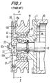
- the compressor includes compressor housing 10 and front end plate 11 attached to an open end of housing 10.
- Drive shaft 12 is rotatably supported within front end plate 11.
- Tubular extension 11a extends outwardly from front end plate 11 and surrounds drive shaft 12.
- Pulley 14 is rotatably supported on the peripheral outer surface of tubular extension 11a through bearing 15. Pulley 14 is securely fitted on the peripheral outer surface of bearing 15 by snap ring 26 disposed between the inner surface of pulley 14 and the inner end surface, with respect to housing 10, of bearing 15. Moreover, snap ring 26 prevents pulley 14 from moving parallel to the rotational axis of drive shaft 12. Bearing 15 is secured between flange 11b and snap ring 19 which is fixed on the peripheral outer surface of tubular extension 11a.
- Armature 13 has a centrally located hole and is secured on the terminal outer end portion of drive shaft 12 by a bolt 12a and a nut 33. Armature 13 is also coupled with drive shaft 12 by the interaction of key 20 on the end of drive shaft 12 with key groove 22 in the centrally located hole of plate-like element 13.
- a plurality of cylindrical members 28 are disposed between the inner axial surface, with respect to housing 10, of armature 13 and the outer axial surface, also with respect to housing 10, of pulley 14 to couple armature 13 to pulley 14. Holes 13a are formed on the inner axial surface of armature 13, and one end of each cylindrical member 28 is disposed therein. The other end of each cylindrical member 28 is disposed in corresponding hole 14a formed on the outer axial surface of pulley 14. Cylindrical members 28 may be made of synthetic resins or metals which are easily broken if a large torque acts between pulley 14 and armature 13, i.e. , a sufficiently large force which acts to rotate pulley 14 with respect to armature 13.
- pulley 14 is disconnected from armature 13 and is free to rotate without resistance applied through armature 13 from motionless drive shaft 12.
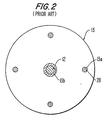
- the maximum acceptable amount of torque and consequently, the size, material, and number of cylindrical members 28 is dependent on the air conditioning system and the compressor with which the coupling mechanism is used.
- the diameters of holes 13a of armature 13 and holes 14a of pulley 14 should be almost the same as the diameter of cylindrical member 28 because both ends of each cylindrical member 28 must be inserted tightly into holes 13a and holes 14a to securely connect armature 6 with pulley 14. Therefore, if these diameters are different from each other due to an error in manufacturing, it usually prevents the armature 13 from being secured to pulley 14 during assembly.
- the driven member may be a compressor for an automotive air conditioning system.
- DE-U-7524954 discloses a coupling mechanism comprising a drive shaft and a flange; the coupling mechanism also including at least two coupling plate members, each of the plate members including a first portion located at an inner radial end of the plate member, a second portion located at an outer radial end of the plate member, and a third portion located between the first portion and the second portion; the third portion connecting the first portion to the second portion and the plate members being radially connectable with the drive shaft and the flange at regular angular intervals around a circumference of the hub of the drive shaft, so that the first portion of each of the plate members is securable to an axial end surface of the armature plate by at least one fastening means and the second portion of each of the plate members is securable to an axial end surface of the pulley by at least one fastening means, each of the plate members including at least one breakaway portion formed in the third portion of the plate member.
- a combination of a coupling mechanism and a compressor comprising a compressor housing having an open end surface, a front end plate attached to the open end surface of the compressor housing, a drive shaft rotatably disposed within the compressor housing the drive shaft having an outer end portion terminating outside of the compressor housing, and a tubular extension extending outwardly from the front end plate parallel to the rotational axis of the drive shaft, a pulley rotationally supported on a bearing fitted on a peripheral outer surface of the tubular extension, an armature including a hub formed at a center of the armature and an armature plate extending outwardly from the hub, the armature connected to the outer end portion of the drive shaft;
- the coupling mechanism including at least two coupling plate members, each of the plate members including a first portion located at an inner radial end of the plate member, a second portion located at an outer radial end of the plate member, and a third portion located between the first portion and the second portion
- a combination of a coupling mechanism and a compressor comprising a compressor housing having an open end surface, a front end plate attached to the open end surface of the compressor housing, a drive shaft rotatably disposed within the compressor housing, the drive shaft having an outer end portion terminating outside of the compressor housing, and a tubular extension extending outwardly from the front end plate parallel to the rotational axis of the drive shaft, a pulley rotationally supported on a bearing fitted on a peripheral outer surface of the tubular extension, an armature including a hub formed at a center of the armature and an armature plate extending outwardly from the hub, the armature plate connected to the outer end portion of the drive shaft;
- the coupling mechanism including a coupling plate member, the plate member including a hole formed through the center of the plate member and an annular portion extending outwardly from the radial edge of the hole of the plate member and at least two projections outwardly extending at regular
- a combination of a coupling mechanism and a compressor comprising a compressor housing having an open end surface, a front end plate attached to the open end surface of the compressor housing, a drive shaft rotatably disposed within the compressor housing, the drive shaft having an outer end portion terminating outside of the compressor housing, and a tubular extension extending outwardly from the front end plate parallel to the rotational axis of the drive shaft, a pulley rotationally supported on a bearing fitted on a peripheral outer surface of the tubular extension, and an armature connected to the outer end portion of the drive shaft;
- the coupling mechanism comprising an armature including a hub formed at the center of the armature and an annular plate extending outwardly from the hub and at least two projections extending outwardly at regular angular intervals around a circumference of the hub from an outer radial edge of the annular plate each of the projections including a first portion located at an inner radial end of the projection,
- Each plate member is connected with the armature and the pulley at regular angular intervals around the circumference of the hub of the armature, so that the first portions of these plate members are secured to an axial end surface of the armature plate by at least one fastening means, and the second portions of the plate members are secured to an axial end surface of the pulley by at least one fastening means.
- Each plate member also includes at least one breakaway portion, i.e. , a portion which fractures or gives way under a predetermined amount of torque or other applied mechanical force, formed at the third portion of the plate member.
- the breakaway portions are designed to be easily broken in the event that they receive a large torque due to compressor failure or malfunction.
- first portions of the plate members are located on a first circular plane which is perpendicular to the axis of the pulley.
- the second portions of the plate members are located on a second circular plane which is perpendicular to the axis of the pulley.
- the first portions of the plate members are positioned with respect to the second portions of the plate members, so that the material of each plate member will be elastically deformed, and the first plane is axially offset from the second circular plane.
- Fig. 1 is a cross-sectional view of a conventional coupling mechanism used on a compressor in accordance with the prior art.
- Fig. 2 is a cross-sectional view of an armature and a coupling plate member of a coupling mechanism taken along line 2-2 of Fig 2.
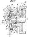
- Fig. 3 is a cross-sectional view of a conventional coupling mechanism used on a compressor in accordance with first embodiment.
- Fig. 4 is a rear end view of an armature and a coupling plate member of a coupling mechanism shown in Fig. 3.
- Fig. 5 is a rear end view of a modified armature and coupling plate member of a coupling mechanism in accordance with a second embodiment of this invention.
- Fig. 6 is a rear end view of a modified armature and coupling plate member of a coupling mechanism in accordance with a third embodiment of this invention.
- the preferred embodiments of the present invention share many components with the compressor depicted in Fig. 1 except for the construction of coupling mechanism between a drive shaft and a pulley. Therefore, similar parts are represented by the same reference numerals as in Fig 1, and the detailed description of the similar parts will be omitted in order to simplify the following description of the preferred embodiments.
- Pulley 14 includes a plurality of holes 14a, e.g. , four holes 14a, formed in an axial end surface of pulley 14 for connecting pulley 14 with coupling plate 7. Holes 14a of pulley 14 are spaced at regular angular intervals i.e. , 90° around the circumference of pulley 14 and around the axial center of pulley 14.
- Armature 6 includes hub 6a formed as a cylinder and armature plate 6b formed as annular plate extending from the axial end of hub 6a. Armature plate 6b includes a plurality of holes be, e.g.
- Coupling plate member 7 which is rectangular in shape, divides plate member 7 into an inner plate portion 7a having a plurality of holes 7f, e.g. , two holes 7f, a center plate portion 7c in the center of plate member 7, and outer plate portion 7b having at least one hole 7e.
- Center plate portion 7c is formed between inner plate portion 7a and outer plate portion 7b and includes a notched or breakaway portion 7d which is partly cut-out from plate member 7.
- center plate portion 7c is more slender than any other portion of plate member 7, so that plate member 7 may be easily broken at center plate portion 7c when excessive torque is applied.
- Four plate members 7 may be radially placed on the inner axial surface of armature 6 at regular angular intervals of 90° around the circumference of armature 6 and around hub 6a and may be connected with armature 6 by four pairs of rivets 8, so that four pairs of holes 7f of plate members 7 correspond to and are aligned with four pairs of holes 6c of armature plate 6b.
- plate member 7 may be made of an elastic material.
- plate members 7 are also secured to pulley 14 at regular angular intervals of 90° around the circumference of pulley 14 and around a radial surface of drive shaft 12, so that bolts 30 pass through washer 9 and holes 7e of each plate member 7.
- Bolts 30 screw into holes 14a of pulley 14, and outer plate portions 7b are axially offset from inner plate portion 7a.
- Center plate portions 7c are inclined toward pulley 14, thereby elastically deforming the material for plate member 7. If a distance L extends between the axial inner surface of plate member 7 which is secured to armature plate 6b by rivets 8 and the axial outer surface of plate member 7 which secured to pulley 14 by bolts 10, distance L must be greater than zero.
- plate member 7 and pulley 14 and armature 6 may not be provided with any holes for connecting by bolts 30 or rivets 8. Instead, armature 6 may be connected to pulley 14 through plate member 7 by means of brazing, spot welding, or the like.
- Coupling plate member 18 includes center hole 18a formed in the center of plate member 18 through which hub 6a passes and an annular portion 18b extending outward from the radial edge of center hole 18a
- Plate member 18 includes a plurality of holes 18e, e.g. , four holes 18c, formed at regular angular intervals, e.g. , 90°, around the circumference of plate member 18 and around hub 6a
- Projection 17 is rectangular shaped and extends outward from the radial edge of annular portion 18b. Projection 17 is divided into inner plate portion 17a, center plate portion 17c, and outer plate portion 17b which has at least one hole 17e.
- Center plate portion 17c is formed between inner plate portion 17a and outer plate portion 17b and includes notched or breakaway portion 17d partly cut out from projection 17. Notched portion 17d is more slender than any other portion of plate member 18, so that it may easily break center plate portion 17c when excessive torque is applied.
- Plate 18 member is connected with armature 6 by a plurality of rivets 8, e.g. , four rivets 8, at regular angular intervals of 90° around the circumference of armature 6 and around hub 6a, so that holes 18c correspond to and are aligned with holes 6c of armature 6.
- plate member 18 is secured to pulley 14 through washer 9 with bolts 30 at regular angular intervals of 90° around the circumference of plate member 18 and around a radial surface of drive shaft 12 so that bolts 30 pass through washer 9 and holes 17e of projection 17 and screw into holes 14a of pulley 14.
- Outer plate portions 17b are axially offset to inner plate portion 17a and center plate portions 17c are inclined toward pulley 14, thereby elastically deforming the material for coupling plate 18.
- projection 17 and pulley 14 and armature 6 may not be provided with any holes for connecting by bolts 30 or rivets 8. Instead, armature 6 may be coupled with pulley 14 through coupling plate 17 by means of brazing spot welding, or the like.
- Armature 16 includes cylindrical hub 16a and annular armature plate 16b extending outward from the axial end of hub 16a. Armature 16 also includes a plurality of projections 27, e.g. , four projections 27, which are rectangular shaped and extend outwardly from the axial edge of armature plate 16b. Projections 27 are radially arranged at regular angular intervals, e.g., 90°, around the circumference of armature plate 16b and around hub 16a of armature 16. Projection 27 includes inner plate portion 27a, center plate portion 27c, and outer plate portion 27b which has at least one hole 27e.
- Center plate portion 27c is formed between inner plate portion 27a and outer plate portion 27b and includes notched portion 27d partly cut out from projection 27. Notched portion 27d is more slender than any other portion of projection 27, so that it may easily break in center plate portion 27c when a large torque is applied. Further, armature 16 and projection 27 may be made of an elastic material.
- Projections 27 may be secured to pulley 14 by bolts 30 at regular angular intervals, e.g. , 90°, around the circumference of pulley 14 and around a radial surface of drive shaft 12, so that bolts 30 pass through washer 9 and holes 27e of projection 27 and screw into hole 14a of pulley 14.
- Outer plate portions 27b are axially offset from inner plate portions 27a, and center plate portions 27c are inclined toward pulley 14, thereby elastically deforming the material of armature 16 and 27.
- FIGs. 3 and 4 During assembly, referring to Figs. 3 and 4, four coupling plates 7 are secured to armature 6 by four pairs of rivets 8, so that holes 6c of armature 6 correspond to and are aligned with holes 7f of plate members 7.
- Four plate members 7 are secured to pulley 14, so that four holes 7e of plate member 7 correspond to and are aligned with four holes 14a of pulley 14, and bolts 30 pass through washer 9 and four holes 7e and screw into holes 14a of pulley 14.
- the diameter of hole 7e is designed to be larger than the diameter of hole 14a of pulley 14.
- armature plate 6b can be easily and quickly secured to pulley 14 by adjusting the center position of hole 7e.
- pulley 14 may be subjected to excessive torque through coupling plate member 7 and bolts 30. This torque may be sufficient to destroy center plate portion 7c of plate member 7 because the center portion 7c is designed to breakaway at breakaway portion 7d when such excessive torque is experienced.
- the maximum amount of torque which the center portion 7c is designed to withstand and the size, material, and number of coupling plate members depends on the air conditioning system and the compressor in which the coupling mechanism is used. Therefore, when center portion 7c breaks away, pulley 14 is disconnected from plate members 7 and is free to rotate without the resistance caused by the rotation of drive shaft 12 as applied to pulley 14.
- center plate portion 7c When center plate portion 7c is broken at breakaway portion 7d, one broken section of center plate portion 7c on inner plate side is separated from and radially parallel to the other broken section of center plate portion 7c on outer plate portion 7b side.
- the broken sections do not contact each other because center plate portion 7b is no longer subject to elastic deformation and portions 7a and 7b of plate member may rotate on parallel planes Moreover, the distance L is large enough to prevent contact or biting between the broken sections.
- coupling plate members 7 are broken at the location of breakaway portions 7d which are located at the predetermined radius from hub 6a of armature 6.
- One broken section of plate member 7 remaining attached to armature 6 does not contact or bite the other broken section of plate member 7 remaining attached to pulley 14. Therefore, unlike the prior art, the invention avoids damaging the engine and other parts of the driving system, such as an alternator, a cooling fan, a power steering which rotates together by a belt.
Landscapes
- Engineering & Computer Science (AREA)
- General Engineering & Computer Science (AREA)
- Mechanical Engineering (AREA)
- Compressors, Vaccum Pumps And Other Relevant Systems (AREA)
- Pulleys (AREA)
- Structures Of Non-Positive Displacement Pumps (AREA)
- Transmission Devices (AREA)
- Auxiliary Drives, Propulsion Controls, And Safety Devices (AREA)
Claims (20)
- Combinaison d'un mécanisme d'accouplement et d'un compresseur, le compresseur comprenant un carter de compresseur (10) muni d'une surface d'extrémité ouverte, une plaque d'extrémité avant (11) fixée à la surface d'extrémité ouverte du carter de compresseur (10), un arbre d'entraínement (12) monté en rotation à l'intérieur du carter de compresseur (10), cet arbre d'entraínement (12) comportant une partie d'extrémité extérieure se terminant à l'extérieur du carter de compresseur (10), et un prolongement tubulaire (11a) partant vers l'extérieur de la plaque d'extrémité avant (11) parallèlement à l'axe de rotation de l'arbre d'entraínement (12), une poulie (14) supportée en rotation par un palier de roulement (15) monté sur une surface extérieure périphérique du prolongement tubulaire (11a), une armature (6) incluant un moyeu (6a) formé au centre de l'armature (6) et une plaque d'armature (6b) partant vers l'extérieur du moyeu (6a), l'armature (6) étant reliée à la partie d'extrémité extérieure de l'arbre d'entraínement (12) ; le mécanisme d'accouplement comprenant au moins deux éléments de plaques d'accouplement (7), chacun des éléments de plaques comprenant une première partie (7a) située à l'endroit d'une extrémité radiale intérieure de l'élément de plaque (7), une seconde partie (7b) située à l'endroit d'une extrémité radiale extérieure de l'élément de plaque (7), et une troisième partie (7c) située entre la première partie (7a) et la seconde partie (7b) ; la troisième partie (7c) reliant la première partie (7a) à la seconde partie (7b), et les éléments de plaques pouvant être reliés radialement à la plaque d'armature (6b) et à la poulie (14) à intervalles angulaires réguliers autour de la circonférence du moyeu (6a) de l'armature (6), de façon que la première partie (7a) de chacun des éléments de plaques peut être fixée à une surface d'extrémité axiale de la plaque d'armature (6b) par au moins un moyen de fixation (8), et que la seconde partie (7b) de chacun des éléments de plaques (7) peut être fixée à une surface d'extrémité axiale de la poulie (14) par au moins un moyen de fixation (30), chacun des éléments de plaques (7) comprenant au moins une partie de séparation (7d) formée dans la troisième partie (7c) de l'élément de plaque,
dans laquelle
la première partie (7a) des éléments de plaques (7) est située essentiellement dans un premier plan qui est perpendiculaire à l'axe de la poulie (14), et la seconde partie (7b) des éléments de plaques (7) est située essentiellement dans un second plan qui est perpendiculaire à l'axe de la poulie (14), le premier plan étant décalé axialement (L) par rapport au second plan et, en cours d'utilisation, la troisième partie (7c) étant déviée élastiquement entre les plans de la première partie et de la seconde partie de façon que, lorsque la partie de séparation (7d) se brise, la section brisée qui est attachée à la première partie (7a) fléchisse vers le plan de la première partie (7a), et que la section brisée qui est attachée à la seconde partie (7b) fléchisse vers le plan de la seconde partie (7b), de telle manière que les parties brisées peuvent tourner sans venir en contact l'une avec l'autre. - Combinaison selon la revendication 1,
dans laquellela poulie (14) comprend un certain nombre de trous (14a) qui sont positionnés à intervalles angulaires réguliers autour de la circonférence de la surface d'extrémité axiale de l'arbre d'entraínement (12),la plaque d'armature (6b) comprend un certain nombre de trous (6c) qui sont positionnés à intervalles angulaires réguliers autour de la circonférence du moyeu (6a) de l'armature (6),la première partie (7a) de l'élément de plaque (7) comprend au moins un trou (7f) formé au centre de la première partie (7a), et la seconde partie (7b) de l'élément de plaque (7) comprend au moins un trou (7e) au centre de la seconde partie (7b),les éléments de plaques (7) sont fixés à la plaque d'armature (6b) à intervalles angulaires réguliers autour de la circonférence du moyeu (6a) de l'armature (6),de façon que les moyens de fixation (8) passent à travers les trous (7f) des éléments de plaques (7) et les trous (6c) de la plaque d'armature (6b), les éléments de plaques (7) étant fixés à la poulie (14) à intervalles angulaires réguliers autour de la circonférence de l'arbre d'entraínement (12), de façon que les moyens de fixation (30) passent à travers les trous (7e) de l'élément de plaque (7) et se vissent dans les trous (14a) de la poulie (14), le diamètre de chacun des trous (7e, 7f) de l'élément de plaque (7) étant plus grand que le diamètre des moyens de fixation (8, 30). - Combinaison selon la revendication 1 ou la revendication 2,
dans laquelle
la première partie (7a) des éléments de plaques (7) est, en cours d'utilisation, soudée par points à une surface d'extrémité axiale de la plaque d'armature (6b), et la seconde partie (7b) des éléments de plaques (7) est, en cours d'utilisation, soudée par points à une surface d'extrémité axiale de la poulie (14). - Combinaison selon la revendication 1,
dans laquelle
le mécanisme d'accouplement comprend deux éléments de plaques (7), les éléments de plaques (7) étant fixés radialement, en cours d'utilisation, à la plaque d'armature (6b) et à la poulie (14), en étant opposés radialement l'un à l'autre autour de la circonférence du moyeu (6a) de l'armature (6). - Combinaison selon la revendication 1,
dans laquelle
le mécanisme d'accouplement comprend trois éléments de plaques (7), les éléments de plaques (7) étant fixés radialement, en cours d'utilisation, à la plaque d'armature (6b) et à la poulie (14), en étant espacés à intervalles angulaires réguliers de 120° autour de la circonférence du moyeu (6a) de l'armature (6). - Combinaison selon la revendication 1,
dans laquelle
le mécanisme d'accouplement comprend quatre éléments de plaques (7), les éléments de plaques (7) étant fixés radialement, en cours d'utilisation, à la plaque d'armature (6b) et à la poulie (14), en étant espacés à intervalles angulaires réguliers de 90° autour de la circonférence du moyeu (6a) de l'armature (6). - Combinaison d'un mécanisme d'accouplement et d'un compresseur, le compresseur comprenant un carter de compresseur (10) muni d'une surface d'extrémité ouverte, une plaque d'extrémité avant (11) fixée à la surface d'extrémité ouverte du carter de compresseur (10), un arbre d'entraínement (12) monté en rotation à l'intérieur du carter de compresseur (10), l'arbre d'entraínement (12) comportant une partie d'extrémité extérieure se terminant à l'extérieur du carter de compresseur (10), et un prolongement tubulaire (11a) partant vers l'extérieur de la plaque d'extrémité avant (11) parallèlement à l'axe de rotation de l'arbre d'entraínement (12), une poulie (14) supportée en rotation par un palier de roulement (15) monté sur la surface périphérique extérieure du prolongement tubulaire (11a), une armature (6) comprenant un moyeu (6a) formé au centre de l'armature (6) et une plaque d'armature (6b) partant vers l'extérieur du moyeu (6a), la plaque d'armature (6b) étant reliée à la partie d'extrémité extérieure de l'arbre d'entraínement (12) ; le mécanisme d'accouplement comprenant un élément de plaque d'accouplement (18), l'élément de plaque (18) comprenant un trou (18a) percé au centre de cet élément de plaque (18), une partie annulaire (18b) partant vers l'extérieur du bord radial du trou (18a) de l'élément de plaque (18), et au moins deux saillies (17) partant vers l'extérieur à intervalles angulaires réguliers autour de la circonférence de la partie annulaire (18b), chacune des saillies comprenant une première partie (17a) située à l'endroit de l'extrémité radiale intérieure de chacune des saillies (17), une seconde partie (17b) située à l'endroit de l'extrémité radiale extérieure de chacune des saillies (17), et une troisième partie (17c) située entre la première partie (17a) et la seconde partie (17b) pour assurer la liaison entre elles, l'élément de plaque (18) pouvant être fixé à la plaque d'armature (6b), de façon que la partie annulaire de l'élément de plaque (18) puisse être fixée concentriquement à la surface d'extrémité axiale de la plaque d'armature (6b) par au moins deux moyens de fixation (8), l'élément de plaque (18) pouvant être fixé à la poulie (14) à intervalles angulaires réguliers autour de la circonférence de l'arbre d'entraínement (12), de façon que la seconde partie (17b) des saillies (17) peut être fixée à la surface d'extrémité axiale de la poulie (14) par au moins un moyen de fixation (8), chacune des saillies (17) comprenant au moins une partie de séparation (17d),
dans laquelle
la première partie (17a) des saillies (17) est située sur un premier plan qui est perpendiculaire à l'axe de la poulie (14) et la seconde partie (17b) des saillies (17) est située sur un second plan qui est perpendiculaire à l'axe de la poulie (14), le premier plan étant décalé axialement (L) par rapport au second plan et, en cours d'utilisation, la troisième partie (17c) étant déviée élastiquement entre les plans de la première partie et de la seconde partie de façon que, lorsque la partie de séparation (17d) se brise, la section brisée attachée à la première partie (17a) fléchisse vers le plan de la première partie (17a) et la section brisée attachée à la seconde partie (17b) fléchisse vers le plan de la seconde partie (17b), de telle manière que les parties brisées puissent tourner sans venir en contact l'une avec l'autre. - Combinaison selon la revendication 7,
dans laquelle
la première partie (7a, 17) de chacune des saillies (7, 17) est soudée par points, en cours d'utilisation, à une surface d'extrémité axiale de la plaque d'armature (6b), et la seconde partie (7, 17b) de chacune des saillies (17) est soudée par points, en cours d'utilisation, à une surface d'extrémité axiale de la poulie (14). - Combinaison selon la revendication 7 ou la revendication 8,
dans laquellela poulie (14) comprend un certain nombre de trous (14a) percés à intervalles angulaires réguliers autour de la circonférence de l'arbre d'entraínement (12) dans la surface d'extrémité axiale de la poulie (14), et la plaque d'armature (6b) comprend un certain nombre de trous (6c) percés à intervalles angulaires réguliers autour de la circonférence du moyeu (6a) de l'armature (6),la première partie de l'élément de plaque (18) comprend au moins un trou (18c) percé au centre de la première partie, etla seconde partie (17b) de la saillie (17) comprend au moins un trou (17e) percé au centre de la seconde partie (17b),la saillie (17) étant reliée à la plaque d'armature (6b) à intervalles angulaires réguliers autour de la circonférence du moyeu (6a) de l'armature (6), de façon que les moyens de liaison (8) passent à travers les trous des saillies et les trous de la plaque d'armature (6b),les saillies (17) étant reliées à la poulie (14) à intervalles angulaires réguliers autour de la circonférence de la poulie (14) de façon que les moyens de liaison (30) passent à travers les trous (17e) des saillies (17) pour se visser dans les trous (14a) de la poulie (14), le diamètre de chacun des trous (18c, 17e) de la saillie étant plus grand que le diamètre des moyens de liaison (8, 30). - Combinaison d'une combinaison selon la revendication 2 ou la revendication 9 avec une poulie,
dans laquelle
la poulie (14) comprend deux trous (14a) percés de deux côtés radialement opposés autour de la circonférence de l'arbre d'entraínement (12), dans la surface d'extrémité axiale de la poulie (14), et la plaque d'armature (6b) comprend deux trous (6c) percés de deux côtés radialement opposés autour de la circonférence du moyeu (6a) de l'armature (6). - Combinaison d'une combinaison selon la revendication 2 ou la revendication 9 avec une poulie,
dans laquelle
la poulie (14) comprend trois trous percés à intervalles angulaires réguliers de 120° autour de la circonférence de l'arbre d'entraínement (12), dans la surface d'extrémité axiale de la poulie (14), et la plaque d'armature (6b) comprend trois trous (6c) percés à intervalles angulaires réguliers de 120° autour de la circonférence du moyeu (6a) de l'armature (6). - Combinaison d'une combinaison selon la revendication 2 ou la revendication 9 avec une poulie,
dans laquelle
la poulie (14) comprend quatre trous percés à intervalles angulaires réguliers de 90° autour de la circonférence de l'arbre d'entraínement (12), dans la surface d'extrémité axiale de la poulie (14), et la plaque d'armature (6b) comprend quatre trous percés à intervalles angulaires réguliers de 90° autour de la circonférence dût moyeu (6a) de l'armature (6). - Combinaison d'un mécanisme d'accouplement et d'un compresseur, le compresseur comprenant un carter de compresseur (10) muni d'une surface d'extrémité ouverte, une plaque d'extrémité avant (11) fixée à la surface d'extrémité ouverte du carter de compresseur (10), un arbre d'entraínement (12) monté en rotation à l'intérieur du carter de compresseur (10), l'arbre d'entraínement (12) comportant une partie d'extrémité extérieure se terminant à l'extérieur du carter de compresseur (10) et un prolongement tubulaire (11a) partant vers l'extérieur de la plaque d'extrémité avant (11) parallèlement à l'axe de rotation de l'arbre d'entraínement (12), une poulie (14) supportée en rotation par un palier de roulement (15) monté sur la surface périphérique extérieure du prolongement tubulaire (11a), et une armature reliée à la partie d'extrémité extérieure de l'arbre d'entraínement (12) ; le mécanisme d'accouplement comprenant une armature (16) incluant un moyeu (16a) formé au centre de l'armature (16), une plaque annulaire (16b) partant vers l'extérieur du moyeu (16a) et au moins deux saillies (27) s'étendant vers l'extérieur à intervalles angulaires réguliers autour de la circonférence du moyeu (16a) en partant du bord radial extérieur de la plaque annulaire (16b), chacune des saillies comprenant une première partie (27a) située à l'endroit de l'extrémité radiale intérieure de la saillie (27), une seconde partie (27b) située à l'endroit de l'extrémité radiale extérieure de la saillie (27), et une troisième partie (27c) située entre la première partie et la seconde partie, la plaque d'armature (16b) pouvant être reliée à la poulie (14), de façon que les secondes parties (27b) des saillies (27) puissent être fixées à la surface d'extrémité axiale de la poulie (14) par au moins un moyen de fixation (30), chacune des saillies comprenant au moins une partie de séparation (27d),
dans laquelle
la première partie (27a) des saillies (27) est située essentiellement dans un premier plan qui est perpendiculaire à l'axe de la poulie (14), et la seconde partie (27b) des saillies (27) est située essentiellement dans un second. plan qui est perpendiculaire à l'axe de la poulie (14), le premier plan étant décalé axialement (L) par rapport au second plan et, en cours d'utilisation, la troisième partie (27c) étant déviée élastiquement entre les plans de la première partie et de la seconde partie de façon que, lorsque la partie de séparation (27d) se brise, la section brisée attachée à la première partie (27a) fléchisse vers le plan de la première partie (27a), et la section brisée attachée à la seconde partie (27b) fléchisse vers le plan de la seconde partie (27b), de telle manière que les parties brisées puissent tourner sans venir en contact l'une avec l'autre. - Combinaison selon l'une quelconque des revendications 1, 7 ou 13,
dans laquelle
la partie de séparation (7d, 17d) de la saillie (7, 17, 27) est située à une distance radiale prédéterminée de l'arbre d'entraínement (12). - Combinaison selon la revendication 13,
dans laquelle
la poulie (14) comprend un certain nombre de trous (14a) percés à intervalles angulaires réguliers autour de la circonférence de l'arbre d'entraínement (12) dans la surface d'extrémité axiale de la poulie (14), et la première partie de la saillie (27) comprend au moins un trou (27e) percé au centre de chacune des premières parties, les saillies (27) étant reliées, en cours d'utilisation, à la poulie (14) de façon que les moyens de liaison (30) passent à travers les trous (27e) des saillies (27) pour se visser dans les trous (14a) de la poulie (14), le diamètre de chacun des trous (14a) des saillies (27) étant plus grand que le diamètre des moyens de liaison (30). - Combinaison selon l'une quelconque des revendications 1, 2, 7 à 9 et 13 à 15,
dans laquelle
la partie de séparation (7d, 17d, 27d) de la saillie (27) est formée par au moins une encoche découpée dans la troisième partie (7c, 17c, 27c) de la saillie. - Combinaison selon l'une quelconque des revendications 7 à 9 et 13 à 15,
dans laquelle
chacune des parties de séparation (17d, 27d) est formée par une paire d'encoche découpées de deux côtés opposés de la troisième partie (17c, 27c) de la saillie (17, 27). - Combinaison selon la revendication 15,
dans laquelle
la poulie (14) comprend deux trous (14a) formés dans des positions radialement opposées autour de la circonférence de l'arbre d'entraínement (12), dans la surface d'extrémité axiale de la poulie (14), et la plaque d'armature (16b) comprend deux saillies (27) formées dans des positions radialement opposées autour de la circonférence du moyeu (16a) de l'armature (16). - Combinaison selon la revendication 15,;
dans laquelle
la poulie (14) comprend trois trous (27e) percés à intervalles angulaires réguliers de 120° autour de la circonférence de l'arbre d'entraínement (12), dans la surface d'extrémité axiale de la poulie (14), et la plaque d'armature (16) comprend trois saillies (27) formées à intervalles angulaires réguliers de 120° autour de la circonférence du moyeu (16a) de l'armature (16). - Combinaison selon la revendication 15,
dans laquelle
la poulie (14) comprend quatre trous percés à intervalles angulaires réguliers de 90° autour de la circonférence de l'arbre d'entraínement (12), dans la surface d'extrémité axiale de la poulie (14), et la plaque d'armature (16b) comprend quatre saillies (27) formées à intervalles angulaires réguliers de 90° autour de la circonférence du moyeu (16a) de l'armature (16).
Applications Claiming Priority (3)
| Application Number | Priority Date | Filing Date | Title |
|---|---|---|---|
| JP6724892 | 1992-09-02 | ||
| JP67248/92 | 1992-09-02 | ||
| JP1992067248U JP2575892Y2 (ja) | 1992-09-02 | 1992-09-02 | プーリー直結型コンプレッサー |
Publications (3)
| Publication Number | Publication Date |
|---|---|
| EP0590794A2 EP0590794A2 (fr) | 1994-04-06 |
| EP0590794A3 EP0590794A3 (fr) | 1994-04-27 |
| EP0590794B1 true EP0590794B1 (fr) | 1999-10-13 |
Family
ID=13339437
Family Applications (1)
| Application Number | Title | Priority Date | Filing Date |
|---|---|---|---|
| EP93306813A Expired - Lifetime EP0590794B1 (fr) | 1992-09-02 | 1993-08-27 | Ensemble d'un dispositif d'accouplement avec un compresseur |
Country Status (8)
| Country | Link |
|---|---|
| US (1) | US5443372A (fr) |
| EP (1) | EP0590794B1 (fr) |
| JP (1) | JP2575892Y2 (fr) |
| KR (1) | KR100218657B1 (fr) |
| AU (1) | AU666031B2 (fr) |
| CA (1) | CA2105350C (fr) |
| DE (1) | DE69326737T2 (fr) |
| SG (1) | SG48778A1 (fr) |
Families Citing this family (33)
| Publication number | Priority date | Publication date | Assignee | Title |
|---|---|---|---|---|
| US5683299A (en) * | 1994-09-14 | 1997-11-04 | Nippondenso Co., Ltd. | Device for transmitting rotational power |
| JPH08319945A (ja) * | 1995-05-25 | 1996-12-03 | Zexel Corp | クラッチレス圧縮機 |
| US5715662A (en) * | 1995-11-17 | 1998-02-10 | Deere & Company | Drive shear device for rotary cutter unit |
| US5826991A (en) * | 1996-01-19 | 1998-10-27 | Interbold | Printer apparatus for automated banking machine |
| JP3671571B2 (ja) * | 1996-02-29 | 2005-07-13 | 株式会社デンソー | 動力伝達装置 |
| JPH10259830A (ja) * | 1997-03-21 | 1998-09-29 | Toyota Autom Loom Works Ltd | 動力伝達構造 |
| DE19919449B4 (de) * | 1998-05-04 | 2015-10-15 | Schaeffler Technologies AG & Co. KG | Triebscheibe |
| JP2000170870A (ja) * | 1998-12-04 | 2000-06-23 | Toyota Autom Loom Works Ltd | 動力伝達機構 |
| DE10066236B4 (de) * | 1999-06-21 | 2016-12-15 | Denso Corporation | Umlauf-Übertragungsvorrichtung mit Drehmoment-Begrenzungseinrichtung |
| US6520684B2 (en) | 2001-03-29 | 2003-02-18 | International Engine Intellectual Property Company, L.L.C. | Bearing retention system |
| JP2002349596A (ja) * | 2001-05-22 | 2002-12-04 | Denso Corp | トルク伝達装置 |
| JP2003035255A (ja) * | 2001-07-23 | 2003-02-07 | Toyota Industries Corp | 動力伝達部材の締結構造 |
| FR2846387A1 (fr) * | 2002-10-24 | 2004-04-30 | Littoral Prec | Limiteur de couple. |
| DE10354049A1 (de) * | 2003-11-19 | 2005-06-30 | Winkelmann Palsis Motortechnik Gmbh & Co.Kg | Vorrichtung zur Übertragung eines Drehmomentes von einem Verbrennungsmotor zu einem Nebenaggregat |
| DE102004002668A1 (de) * | 2004-01-18 | 2005-09-22 | Bakelite Ag | Vorrichtung zur Übertragung eines Drehmomentes von einem Motor zu einem Kompressor |
| KR101089560B1 (ko) * | 2004-03-18 | 2011-12-05 | 한라공조주식회사 | 클러치리스 압축기의 동력전달장치 |
| JP4464730B2 (ja) * | 2004-04-05 | 2010-05-19 | カルソニックカンセイ株式会社 | プーリおよびこれを用いた動力伝達装置 |
| JP2005315387A (ja) * | 2004-04-30 | 2005-11-10 | Sanden Corp | 動力伝達装置 |
| US20060021316A1 (en) * | 2004-07-28 | 2006-02-02 | Harkcom Melanie W | Disc cutterbar shear device |
| DE102004056487B4 (de) * | 2004-11-23 | 2006-10-19 | Winkelmann Powertrain Components Gmbh & Co. Kg | Mitnehmerscheibe |
| KR101156772B1 (ko) * | 2006-09-26 | 2012-06-18 | 한라공조주식회사 | 압축기의 동력전달구조 |
| FR2916027B1 (fr) * | 2007-05-09 | 2009-11-06 | Skf Ab | Dispositif de transmission de couple. |
| US8371947B2 (en) * | 2007-06-01 | 2013-02-12 | Halla Climate Control Corp. | Power transmission device of clutchless compressor |
| FR2946716B1 (fr) * | 2009-06-12 | 2011-07-08 | Skf Ab | Dispositif de poulie a anneau elastique premonte et procede de montage du dispositif. |
| US8753237B2 (en) * | 2011-03-17 | 2014-06-17 | Honda Motor Co., Ltd. | Alternator with decoupling device |
| US8517698B2 (en) | 2011-03-17 | 2013-08-27 | Delphi Technologies, Inc. | Air conditioning compressor over-torque protector |
| JP2012225488A (ja) * | 2011-04-22 | 2012-11-15 | Toyota Industries Corp | トルク伝達機構 |
| KR101282270B1 (ko) * | 2011-04-26 | 2013-07-10 | 주식회사 지엔원 | 코일리스 클러치의 동력전달 차단장치 |
| US9371835B2 (en) | 2013-07-19 | 2016-06-21 | Praxair Technology, Inc. | Coupling for directly driven compressor |
| FR3041391B1 (fr) * | 2015-09-17 | 2018-09-21 | Safran Electrical & Power | Ventilateur pour un groupe de refroidissement d'aeronef |
| US10717518B2 (en) * | 2018-02-21 | 2020-07-21 | Garmin International, Inc. | Aviation actuator assembly with mechanical fuse |
| US11203842B2 (en) * | 2019-10-10 | 2021-12-21 | Caterpillar Paving Products Inc. | Torque limiting device for road milling machine |
| EP4074596B1 (fr) * | 2021-04-12 | 2023-05-31 | Ratier-Figeac SAS | Disque de frein avec fusible thermique intégré et procédé de fabrication d'un disque de frein avec fusible thermique intégré |
Family Cites Families (31)
| Publication number | Priority date | Publication date | Assignee | Title |
|---|---|---|---|---|
| US490313A (en) * | 1893-01-24 | Carl schlickeysen | ||
| US1326869A (en) * | 1919-12-30 | Elastic-fluid turbine | ||
| DE7524954U (de) * | 1976-11-04 | Atec Weiss Kg, 4044 Kaarst | Kupplung für zwei im wesentlichen fluchtende Wellen mit einer überlastsicherung zum Begrenzen des Drehmoments | |
| US1343152A (en) * | 1919-06-14 | 1920-06-08 | William C Olson | Pulley attachment for motors |
| US1498281A (en) * | 1923-12-01 | 1924-06-17 | Jones Stanley | Overload release coupling |
| GB888116A (en) * | 1958-09-26 | 1962-01-24 | Gaetano Thomas Trigilio | Drive mechanism |
| US2892329A (en) * | 1958-09-26 | 1959-06-30 | Gaetano T Trigilio | Drive mechanism |
| US3071945A (en) * | 1961-06-26 | 1963-01-08 | Ernest S Shomo | Shear key |
| US3472046A (en) * | 1967-11-01 | 1969-10-14 | Allis Chalmers Mfg Co | Torque limiting safety device |
| US3662619A (en) * | 1970-08-26 | 1972-05-16 | Gen Electric | Fail-safe rotary machine |
| US3861829A (en) * | 1973-04-04 | 1975-01-21 | Borg Warner | Variable capacity wobble plate compressor |
| JPS539670B2 (fr) * | 1975-02-14 | 1978-04-07 | ||
| DE2640989C2 (de) * | 1976-09-11 | 1978-08-10 | Atec Weiss Kg, 4044 Kaarst | Kupplung mit Überlastsicherung |
| SU713540A3 (ru) * | 1976-12-18 | 1980-01-30 | Тиссен Индустри Аг (Фирма) | Крутильно-упруга муфта и способ ее изготовлени |
| DE2729041A1 (de) * | 1977-06-28 | 1979-01-11 | Johann Hochreuter | Brechleistensicherheitskupplung |
| EP0013175B1 (fr) * | 1978-12-25 | 1983-06-22 | Sanden Corporation | Embrayage électromagnétique |
| US4624354A (en) * | 1980-11-10 | 1986-11-25 | Sanden Corporation | Electromagnetic clutch |
| DE3043744C2 (de) * | 1980-11-20 | 1982-11-25 | A. Friedr. Flender Gmbh & Co Kg, 4290 Bocholt | Verfahren zur Verringerung der Abschaltspanne bei Überlast und eine Sicherheitskupplung zur Durchführung des Verfahrens |
| JPS5924538U (ja) * | 1982-08-09 | 1984-02-15 | サンデン株式会社 | 電磁クラツチ |
| US4616742A (en) * | 1983-03-30 | 1986-10-14 | Sanden Corporation | Spring coupling for an electromagnetic clutch |
| JPS6045934U (ja) * | 1983-09-05 | 1985-04-01 | サンデン株式会社 | 電磁スプリングクラッチ |
| DE3366576D1 (en) * | 1983-06-18 | 1986-11-06 | Vickers Systems Gmbh | Double pump |
| JPS6045935U (ja) * | 1983-09-05 | 1985-04-01 | サンデン株式会社 | 電磁スプリングクラッチ |
| US4694945A (en) * | 1984-10-16 | 1987-09-22 | Sanden Corporation | Electromagnetic clutch with an improved magnetic rotatable member |
| JPS62158226U (fr) * | 1986-03-28 | 1987-10-07 | ||
| JPS6323031A (ja) * | 1986-07-14 | 1988-01-30 | Sanden Corp | 電磁クラツチ |
| JPH0639105Y2 (ja) * | 1986-07-23 | 1994-10-12 | サンデン株式会社 | プ−リ−直結型コンプレッサ− |
| JPH0538250Y2 (fr) * | 1986-10-06 | 1993-09-28 | ||
| JPS63308229A (ja) * | 1987-06-05 | 1988-12-15 | Sanden Corp | クラッチロ−タの構造 |
| JPH01136727U (fr) * | 1988-03-15 | 1989-09-19 | ||
| US4932280A (en) * | 1988-11-03 | 1990-06-12 | Sundstrand Corporation | Coaxial drive shaft system with shearable section |
-
1992
- 1992-09-02 JP JP1992067248U patent/JP2575892Y2/ja not_active Expired - Lifetime
-
1993
- 1993-08-24 AU AU44817/93A patent/AU666031B2/en not_active Ceased
- 1993-08-27 DE DE69326737T patent/DE69326737T2/de not_active Expired - Fee Related
- 1993-08-27 EP EP93306813A patent/EP0590794B1/fr not_active Expired - Lifetime
- 1993-08-27 SG SG1996001586A patent/SG48778A1/en unknown
- 1993-09-01 CA CA002105350A patent/CA2105350C/fr not_active Expired - Fee Related
- 1993-09-01 US US08/114,188 patent/US5443372A/en not_active Expired - Lifetime
- 1993-09-02 KR KR1019930017452A patent/KR100218657B1/ko not_active Expired - Fee Related
Also Published As
| Publication number | Publication date |
|---|---|
| DE69326737D1 (de) | 1999-11-18 |
| JP2575892Y2 (ja) | 1998-07-02 |
| CA2105350A1 (fr) | 1994-03-03 |
| AU4481793A (en) | 1994-03-10 |
| KR100218657B1 (ko) | 1999-09-01 |
| KR940007373A (ko) | 1994-04-27 |
| EP0590794A3 (fr) | 1994-04-27 |
| DE69326737T2 (de) | 2000-04-06 |
| CA2105350C (fr) | 1998-07-07 |
| AU666031B2 (en) | 1996-01-25 |
| SG48778A1 (en) | 1998-05-18 |
| JPH0625598U (ja) | 1994-04-08 |
| EP0590794A2 (fr) | 1994-04-06 |
| US5443372A (en) | 1995-08-22 |
Similar Documents
| Publication | Publication Date | Title |
|---|---|---|
| EP0590794B1 (fr) | Ensemble d'un dispositif d'accouplement avec un compresseur | |
| EP0254295A1 (fr) | Dispositif d'accouplement pour un compresseur | |
| US4828090A (en) | Electromagnetic clutch | |
| US4799578A (en) | Apparatus for preventing heat damage in an electromagnetic clutch | |
| EP2500596B1 (fr) | Protecteur de surcouple pour compresseur de climatisation | |
| US6494799B1 (en) | Power transmission device | |
| US5295038A (en) | Electromagnetic clutch | |
| US6893368B2 (en) | Driving force transmission apparatus | |
| US7017726B2 (en) | Electromagnetic clutch | |
| JP4273595B2 (ja) | 動力伝達装置 | |
| JP2008157461A (ja) | 軸方向スペーサを備えた軸方向一方向クラッチ | |
| JPH0942411A (ja) | 動力伝達装置 | |
| JP2002021876A (ja) | 電磁スプリングクラッチ | |
| US5404980A (en) | Electromagnetic clutch with failure protection apparatus | |
| JP4078761B2 (ja) | 動力伝達装置 | |
| CA2252178C (fr) | Dispositif d'accouplement d'arbre d'entrainement | |
| US4796743A (en) | Clutch release bearing assembly | |
| WO2006089102A1 (fr) | Ensemble d’articulations avec collerette de centrage | |
| US6397992B1 (en) | Inner hub for clutch/brake | |
| EP0892189B1 (fr) | Embrayage uni-directionnel avec tocs d'entraínement groupés et cage | |
| JP2000179568A (ja) | 動力伝達装置 | |
| JP2001032903A (ja) | 動力伝達機構 | |
| KR100607587B1 (ko) | 클러치리스 압축기 | |
| JP2003139216A (ja) | 動力伝達機構 | |
| KR20210074861A (ko) | 동력전달장치 |
Legal Events
| Date | Code | Title | Description |
|---|---|---|---|
| PUAI | Public reference made under article 153(3) epc to a published international application that has entered the european phase |
Free format text: ORIGINAL CODE: 0009012 |
|
| PUAL | Search report despatched |
Free format text: ORIGINAL CODE: 0009013 |
|
| AK | Designated contracting states |
Kind code of ref document: A2 Designated state(s): DE FR GB IT SE |
|
| AK | Designated contracting states |
Kind code of ref document: A3 Designated state(s): DE FR GB IT SE |
|
| 17P | Request for examination filed |
Effective date: 19940930 |
|
| 17Q | First examination report despatched |
Effective date: 19950915 |
|
| TPAD | Observations filed by third parties |
Free format text: ORIGINAL CODE: EPIDOS TIPA |
|
| GRAG | Despatch of communication of intention to grant |
Free format text: ORIGINAL CODE: EPIDOS AGRA |
|
| GRAG | Despatch of communication of intention to grant |
Free format text: ORIGINAL CODE: EPIDOS AGRA |
|
| GRAG | Despatch of communication of intention to grant |
Free format text: ORIGINAL CODE: EPIDOS AGRA |
|
| GRAH | Despatch of communication of intention to grant a patent |
Free format text: ORIGINAL CODE: EPIDOS IGRA |
|
| GRAH | Despatch of communication of intention to grant a patent |
Free format text: ORIGINAL CODE: EPIDOS IGRA |
|
| GRAA | (expected) grant |
Free format text: ORIGINAL CODE: 0009210 |
|
| AK | Designated contracting states |
Kind code of ref document: B1 Designated state(s): DE FR GB IT SE |
|
| REF | Corresponds to: |
Ref document number: 69326737 Country of ref document: DE Date of ref document: 19991118 |
|
| ITF | It: translation for a ep patent filed | ||
| ET | Fr: translation filed | ||
| PGFP | Annual fee paid to national office [announced via postgrant information from national office to epo] |
Ref country code: SE Payment date: 20000804 Year of fee payment: 8 |
|
| PLBE | No opposition filed within time limit |
Free format text: ORIGINAL CODE: 0009261 |
|
| STAA | Information on the status of an ep patent application or granted ep patent |
Free format text: STATUS: NO OPPOSITION FILED WITHIN TIME LIMIT |
|
| PGFP | Annual fee paid to national office [announced via postgrant information from national office to epo] |
Ref country code: GB Payment date: 20000823 Year of fee payment: 8 |
|
| 26N | No opposition filed | ||
| PG25 | Lapsed in a contracting state [announced via postgrant information from national office to epo] |
Ref country code: GB Free format text: LAPSE BECAUSE OF NON-PAYMENT OF DUE FEES Effective date: 20010827 |
|
| PG25 | Lapsed in a contracting state [announced via postgrant information from national office to epo] |
Ref country code: SE Free format text: LAPSE BECAUSE OF NON-PAYMENT OF DUE FEES Effective date: 20010828 |
|
| EUG | Se: european patent has lapsed |
Ref document number: 93306813.2 |
|
| GBPC | Gb: european patent ceased through non-payment of renewal fee |
Effective date: 20010827 |
|
| PG25 | Lapsed in a contracting state [announced via postgrant information from national office to epo] |
Ref country code: IT Free format text: LAPSE BECAUSE OF NON-PAYMENT OF DUE FEES;WARNING: LAPSES OF ITALIAN PATENTS WITH EFFECTIVE DATE BEFORE 2007 MAY HAVE OCCURRED AT ANY TIME BEFORE 2007. THE CORRECT EFFECTIVE DATE MAY BE DIFFERENT FROM THE ONE RECORDED. Effective date: 20050827 |
|
| PGFP | Annual fee paid to national office [announced via postgrant information from national office to epo] |
Ref country code: DE Payment date: 20080912 Year of fee payment: 16 |
|
| PGFP | Annual fee paid to national office [announced via postgrant information from national office to epo] |
Ref country code: FR Payment date: 20080818 Year of fee payment: 16 |
|
| REG | Reference to a national code |
Ref country code: FR Ref legal event code: ST Effective date: 20100430 |
|
| PG25 | Lapsed in a contracting state [announced via postgrant information from national office to epo] |
Ref country code: FR Free format text: LAPSE BECAUSE OF NON-PAYMENT OF DUE FEES Effective date: 20090831 Ref country code: DE Free format text: LAPSE BECAUSE OF NON-PAYMENT OF DUE FEES Effective date: 20100302 |