EP0596439A2 - Procédé de fabrication d'un disque-mère utilisable pour la production de disques optiques - Google Patents
Procédé de fabrication d'un disque-mère utilisable pour la production de disques optiques Download PDFInfo
- Publication number
- EP0596439A2 EP0596439A2 EP93117676A EP93117676A EP0596439A2 EP 0596439 A2 EP0596439 A2 EP 0596439A2 EP 93117676 A EP93117676 A EP 93117676A EP 93117676 A EP93117676 A EP 93117676A EP 0596439 A2 EP0596439 A2 EP 0596439A2
- Authority
- EP
- European Patent Office
- Prior art keywords
- photoresist film
- photoresist
- portions
- substrate
- films
- Prior art date
- Legal status (The legal status is an assumption and is not a legal conclusion. Google has not performed a legal analysis and makes no representation as to the accuracy of the status listed.)
- Withdrawn
Links
Images


Classifications
-
- G—PHYSICS
- G11—INFORMATION STORAGE
- G11B—INFORMATION STORAGE BASED ON RELATIVE MOVEMENT BETWEEN RECORD CARRIER AND TRANSDUCER
- G11B7/00—Recording or reproducing by optical means, e.g. recording using a thermal beam of optical radiation by modifying optical properties or the physical structure, reproducing using an optical beam at lower power by sensing optical properties; Record carriers therefor
- G11B7/24—Record carriers characterised by shape, structure or physical properties, or by the selection of the material
- G11B7/26—Apparatus or processes specially adapted for the manufacture of record carriers
- G11B7/261—Preparing a master, e.g. exposing photoresist, electroforming
Definitions
- the present invention relates to a method of making a master disc usable for the production of optical discs having information recorded therein at a high density.
- a master disc usable for the production of optical discs is generally made by coating a photoresist film on a disc substrate made of glass of which the surface has been ground; partially exposing the photoresist film to a laser beam intensity-modulated according to information to be recorded; and developing the substrate with the photoresist film to thereby form signal pits or grooves each having a depth corresponding to the extent to which the photoresist film has been exposed to the laser beam.
- Reproduction of high-density optical discs can be achieved by reducing the wavelength of a laser beam to be radiated thereto or by enlarging the numerical aperture (NA) of an objective lens by which the laser beam is converged.
- NA numerical aperture
- the wavelength of the laser beam has a limitation of 670 nm
- the numerical aperture of the objective lens has a limitation of 0.6.
- the depth of a row of signal pits is chosen to be X/(4n) and that of another row of signal pits radially adjoining it is chosen to be x/(8n).
- a beam reflected from each signal pit is received by a light detector divided into two light detection segments. The sum of two signals from respective light detection segments is used to reproduce the row of signal pits having the depth of X/(4n), whereas the difference between the two signals is used to reproduce the row of signal pits having the depth of X/(8n).
- Japanese Laid-open Patent Publication (unexamined) No. 54-136303 discloses a method of forming two kinds of signal pits having different depths on a master disc. According to this method, the intensity of light is changed during recording of the signal pits. More specifically, light having a weak intensity is radiated to a substrate of the master disc during recording of shallow signal pits, whereas light having a strong intensity is radiated to the substrate during recording of deep signal pits. Subsequent development of the substrate results in formation of the two kinds of signal pits having different depths.
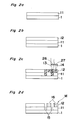
- Figs. 1 a to 1 depict processes indicating such a conventional method.
- a disc substrate 1 made of, for example, glass is initially flattened by grinding or the like, and a positive photoresist film 2 is subsequently formed thereon, as shown in Fig. 1 a, by the use of, for example, a spin coating technique.
- a first beam 6 of an intensity sufficient to allow the photoresist film 2 to be removed completely across its thickness during a subsequent developing process is radiated to portions of the surface of the disc substrate 1 where recording of the deep signal pits is desired.
- a second beam 7 of such an intensity as to allow the photoresist film 2 to be removed to a depth half the thickness thereof during the subsequent developing process is radiated to other portions of the surface of the disc substrate 1 where recording of the shallow signal pits is desired.
- the portions exposed to the beams 6 and 7 are indicated by hatching and are denoted by 3.
- desired signal pits 4 and 5 having different depths are formed on the disc substrate 1.
- Fig. 1 depicts the master disc obtained in the above-described manner.
- the conventional method mentioned above requires appropriately controlling the light intensity to remove all or about half of the photoresist film 2 according to the location of the signal pits, variations in light intensity or those in developing conditions cause a change in depth of the signal pits. Accordingly, the above conventional method has difficulties in stably forming the two kinds of signal pits having different depths.
- the present invention has been developed to overcome the above-described disadvantages.
- the method according to the present invention comprises the steps of:
- a boundary layer is interposed between the first and second photoresist films.
- the boundary layer may be a modified layer formed on the surface of the first photoresist film by baking the first photoresist film.
- the boundary layer may be a modified layer formed on the surface of the first photoresist film by developing the first photoresist film.
- a CEL Contrast Enhanced Layer
- the first beam has an intensity sufficient to cause both of the first and second photoresist films to be exposed
- the second beam has an intensity sufficient to cause only the second photoresist film to be exposed.
- the first photoresist film has a sensitivity lower than that of the second photoresist film.
- the sensitivity of the first photoresist film can be made lower than that of the second photoresist film by baking the first photoresist film without the second photoresist film being baked. The baking treatment is effectively carried out in an atmosphere containing at least one of nitrogen, oxygen, argon, and krypton.
- a pattern of signal pits recorded by the second beam has a depth equal to the thickness of the second photoresist film, because such a pattern is formed by those portions of the second photoresist film which are exposed to the second beam and are removed during the development.
- another pattern of signal pits recorded by the first beam has a depth equal to the sum of the thickness of the first photoresist film and that of the second photoresist film (and that of the boundary layer if this layer is interposed between the two photoresist films).
- the boundary layer interposed between the two photoresist films not only prevents the second beam from entering the first photoresist film, but also makes good the configuration of signal pits recorded in the second photoresist film by flattening bottoms of such signal pits. If the boundary layer is interposed between the two photoresist films, the sensitivity of the first photoresist film may be the same as that of the second photoresist film.
- the first and second photoresist films have different maximum absorption wavelengths.
- the first beam has a first wavelength capable of causing both of the first and second photoresist films to be exposed, while the second beam has a second wavelength capable of causing only the second photoresist film to be exposed.
- Each of the first and second photoresist films may be of a positive type.
- the maximum absorption wavelength of the first photoresist film is so chosen as to be shorter than that of the second photoresist film.
- the first wavelength is so chosen as to be shorter than the maximum absorption wavelength of the first photoresist film, while the second wavelength is so chosen as to be longer than the maximum absorption wavelength of the first photoresist film, but shorter than the maximum absorption wavelength of the second photoresist film.
- the method according to the present invention may further comprise, prior to the step (e), the steps of: developing the substrate having the first and second photoresist films to thereby form first and second recesses defined in the substrate and having different depths; and etching the substrate with the first and second photoresist films employed as a mask.
- a method of making the master disc having first and second signal patterns of different heights comprises the steps of:
- the use of negative photoresist films is preferred.
- the first photoresist film is so chosen as to have a maximum absorption wavelength longer than that of the second photoresist film.
- the first beam is so chosen as to have a wavelength shorter than the maximum absorption wavelength of the second photoresist film, while the second beam is so chosen as to have a wavelength shorter than the maximum absorption wavelength of the first photoresist film, but longer than the maximum absorption wavelength of the second photoresist film.
- a first photoresist film 11 is initially formed on a disc substrate 1 by the use of, for example, a spin coating technique.
- a second photoresist film 12 having a sensitivity higher than that of the first photoresist film 11 is subsequently coated, as shown in Fig. 2b, over the first photoresist film 11.
- first and second beams 13 and 14 appropriately converged by first and second objective lenses 26 and 27, respectively, are radiated to desired portions of the first and second photoresist films 11 and 12.
- Subsequent development of the disc substrate 1 results in removal of such portions of the first and second photoresist films 11 and 12 exposed to the two beams 13 and 14.
- a master disc M thus obtained is shown in Fig. 2d and has plural rows of signal pits 15 and 16 having different depths.
- a row of signal pits 15 formed by the first beam 13 and another row of signal pits 16 formed by the second beam 14 adjoin each other while extending either spirally or coaxially.
- the first beam 13 has an intensity sufficient to cause both of the first and second photoresist films 11 and 12 to be exposed
- the second beam 14 has an intensity sufficient to cause only the second photoresist film 12 to be exposed.
- the first photoresist film 11 disposed below the second photoresist film 12 is insensitive to and, therefore, is not exposed to the second beam 14 because the sensitivity of the first photoresist film 11 is lower than that of the second photoresist film 12.
- the depth of the signal pits 15 is equal to the sum of the thickness of the first photoresist film 11 and the thickness of the second photoresist film 12, and that of the signal pits 16 is equal to the thickness of the second photoresist film 12.
- the sensitivity of the first photoresist film 11 can be made lower than that of the second photoresist film 12 by conducting a baking treatment at 80 ° C for thirty minutes after the coating of the first photoresist film 11 without the second photoresist film 12 being baked.
- the configuration of the signal pits can be improved by forming a boundary layer between the two photoresist films 11 and 12.
- a first photoresist film 11 is initially formed on a substrate 1, as shown in Fig. 3a, by the use of the spin coating technique or the like.
- a contrast enhanced layer (CEL) is subsequently coated, as shown in Fig. 3b, over the first photoresist film 11, thereby forming a boundary layer 17.
- a second photoresist film 12 is coated, as shown in Fig. 3c, over the boundary layer 17.
- the CEL has a light absorbance considerably greater than that of the photoresist films 11 and 12, and the transmittance thereof is non-linear relative to the quantity of exposure. Because of this, the presence of the CEL enhances the contrast of imagewise light entering the first photoresist film 11 therethrough.
- first and second beams 13 and 14 appropriately converged by first and second objective lenses 26 and 27, respectively, are radiated to the first and second photoresist films 11 and 12 for the recording of respective signal pits 18 and 19 on the substrate 1.
- the first beam 13 has an intensity sufficient to cause both of the photoresist films 11 and 12 to be exposed
- the second beam 14 has an intensity sufficient to cause only the second photoresist film 12 to be exposed.
- the first photoresist film 11 disposed below the boundary layer 17 is not exposed to the second beam 14 because the boundary layer 17 prevents the second beam 14 from entering the first photoresist film 11. Accordingly, the signal pits 19 can be configured into desired ones each having a flat bottom formed by the boundary layer 17.
- the process of removing the boundary layer 17 can be omitted by the use of a water-soluble material manufactured by, for example, General Electric Co., Ltd. as the CEL because the CEL exposed to the second beam 14 dissolves together with the second photoresist film 12 during the developing process.
- the CEL may be replaced by a modified layer formed on the surface of the first photoresist film 11.
- a modified layer can be formed, after the coating of the first photoresist film 11 over the substrate 1, by baking the substrate 1, for example, at 80 ° C for thirty minutes in an atmosphere containing at least one of nitrogen, oxygen, argon, and krypton.
- the modified layer may be formed on the surface of the first photoresist film 11 by developing the substrate 1 after the coating of the first photoresist film 11 thereon.
- the first photoresist film 11 may have a sensitivity lower than that of the second photoresist film 12. However, because the boundary layer 17 is interposed between the two photoresist films 11 and 12, the first photoresist film 11 may be identical with the second photoresist film 12.
- the signal pits of different depths are formed by radiating light of different wavelengths to two photoresist films having different maximum absorption wavelengths.
- photosensitive materials have the property of being exposed to light having a wavelength shorter than a specific wavelength.
- maximum absorption wavelength as employed throughout this specification is defined as meaning the maximum wavelength of the spectral band of light which a certain photosensitive material absorbs.
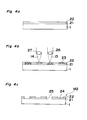
- a substrate 1 made of, for example, glass having a surface flattened by grinding or the like is initially coated with a first positive photoresist by the use of, for example, the spin coating technique.
- the coated first positive photoresist is then baked to thereby form a first photoresist film 21.
- a second positive photoresist having a maximum absorption wavelength longer than that of the first photoresist film 21 is coated over the first photoresist film 21 by the use of the spin coating technique or the like to thereby form a second photoresist film 22.
- a first beam 13 having a wavelength shorter than the maximum absorption wavelength of the first photoresist film 21 and a second beam 14 having a wavelength longer than the maximum absorption wavelength of the first photoresist film 21 but shorter than the maximum absorption wavelength of the second photoresist film 22 are intensity-modulated according to respective signals to be recorded using, for example, an optical modulator in which the electro-optical effect is utilized.
- an optical modulator in which the electro-optical effect is utilized.
- Fig. 4c depicts a master disc M2 obtained in the above-described manner.
- the depth of the shallow signal pits 24 is determined by the thickness of the second photoresist film 22, while the depth of the deep signal pits 25 is determined by the sum of the thickness of the first photoresist film 21 and that of the second photoresist film 22. Accordingly, the depth of the signal pits can be maintained substantially constant.
- a stamper made of a metal such as, for example, nickel is prepared by the use of the master disc obtained in this way. Then, a large number of replicas are duplicated from the stamper with the use of, for example, an injection technique.
- any suitable material other than glass may be employed as the material of the substrate if the surface of the substrate can be flattened by any suitable means.
- a metal such as nickel, copper or the like, or a synthetic resin such as an acrylic resin can be employed for the substrate.
- the thickness of the first photoresist film 21 is so chosen as to be equal to a value obtained by dividing the thickness difference between the two kinds of signal pits 24 and 25 by the refractive index n of the substrate of the replica.
- the thickness of the second photoresist film 22 is so chosen as to be equal to the sum of the depth of the shallow signal pits 24 divided by the refractive index n of the substrate of the replica and the amount of thickness reduction of unexposed portions cause by the development.
- the amount of thickness reduction during the development varies according to the developing conditions and normally ranges from 5nm to 15nm.
- a quinonediazido-novolak-based resist, a chemically amplified resist or the like can be employed for the positive photoresist film.
- quinonediazido-novolak-based resist In the case of the quinonediazido-novolak-based resist, quinonediazido employed as the photosensitive material functions as a solution inhibitor against a water-soluble novolak resin and, hence, the novolak resin does not dissolve in an alkaline developing solution. However, exposure of quinonediazido to light loses the solution inhibiting function thereof, and consequently, the novolak resin dissolves in the alkaline developing solution to thereby form a desired signal pattern. In this case, the maximum absorption wavelength, i.e., the wavelength of light to which the photoresist films are exposed can be changed by changing the kind of quinonediazido.
- an acid generator is used as the photosensitive material. While acid generated by exposure is acting as a catalyst, decomposition of the resin is activated as if it has caused a chain reaction, thereby enhancing the solubility of the resin in the developing solution. As a result, the desired signal pattern can be readily formed on the substrate.
- the maximum absorption wavelength can be changed by changing the kind of the acid generator and, hence, the wavelength of light to which the photoresist films are exposed can be changed.
- the wavelength of light to which the photoresist films are exposed can be changed by changing the photosensitive material.
- a gas laser such as, for example, an argon laser or a krypton laser, or harmonics emitted from a solid laser such as, for example, a YAG laser can be used as light for recording signals.
- the light for recording the signals is focused on the substrate by an objective lens 26 or 27 and means for driving the objective lens 26 or 27 in the axial direction of the lens for focusing control. More specifically, the two beams having different wavelengths, i.e., the first beam 13 having a wavelength shorter than the maximum absorption wavelength of the first photoresist film 21 and the second beam 14 having a wavelength longer than the maximum absorption wavelength of the first photoresist film 21 but shorter than the maximum absorption wavelength of the second photoresist film 22 are focused on the substrate by the associated objective lenses 26 and 27, respectively.
- the focal length of a lens varies according to the wavelength of light traveling therethrough.
- the two beams 13 and 14 are simultaneously focused on the substrate by collimating one of them before it enters the associated objective lens, and by rendering the other beam to be a slightly diverging or converging beam before it enters the associated objective lens.
- the signal pits are recorded on a spiral track or a plurality of coaxially aligned tracks.
- the spiral track although continuous from one end to the opposite end, includes a plurality of turns each extending 360 about an axis of rotation of the disc. Because the distance between two adjoining turns or tracks is considerably short, one or both of the two beams are slightly inclined to form a given angle therebetween before they enter the associated objective lenses. By doing so, the two beams are simultaneously focused on the substrate while maintaining a desired distance therebetween, thereby enabling signal pits having different depths to be simultaneously recorded on two adjoining turns or tracks.
- the master disc having two kinds of signal pits of different depths can be readily produced by the use of the method according to the above-described embodiment.
- a substrate 1 made of, for example, a metal having a surface flattened by grinding or the like is initially coated with a first positive photoresist by the use of, for example, the spin coating technique.
- the first positive photoresist is then baked to thereby form a first photoresist film 31 on the substrate 1.
- a second positive photoresist having a maximum absorption wavelength longer than that of the first photoresist film 31 is coated over the first photoresist film 31 by the use of the spin coating technique or the like to thereby form a second photoresist film 32 on the first photoresist film 31.
- a first beam 13 having a wavelength shorter than the maximum absorption wavelength of the first photoresist film 31 and a second beam 14 having a wavelength longer than the maximum absorption wavelength of the first photoresist film 31 but shorter than the maximum absorption wavelength of the second photoresist film 32 are intensity-modulated according to respective signals to be recorded using, for example, an optical modulator in which the electro-optical effect is utilized.
- an optical modulator in which the electro-optical effect is utilized.
- the substrate 1 is then subjected to etching with the first and second photoresist films 31 and 32 employed as a mask.
- signal pits 36 and 37 having different depths are formed on the surface of the substrate 1, as shown in Fig. 5d.
- the depth of the signal pits 36 and 37 depends upon that of the recesses 34 and 35 defined in the first and second photoresist films 31 and 32, respectively.
- the remaining photoresist films on the substrate 1 are removed with the use of an organic solvent such as, for example, a remover, or by ashing with the use of oxygen plasma.
- an organic solvent such as, for example, a remover
- Fig. 5e depicts a master disc M3 having two kinds of signal pits of different depths and obtained in the above-described manner.
- the substrate 1 may be the same as that employed in the first embodiment, the use of a material having an etching rate different from that of the photoresist films 31 and 32 is preferred.
- the photoresist films 31 and 32 may be the same as those employed in the first embodiment.
- any one of ion beam etching, reactive ion beam etching, wet etching and the like can be employed.
- anisotropic etching for example, ion beam etching employing an ion gun for emitting an argon ion beam, is preferred whereby etching can be carried out in a direction perpendicular to the substrate.
- the depth of the signal pits can be controlled by the time period during which the etching is being carried out. Accordingly, the signal pits of desired depths can be stably obtained without being affected by variations in thickness of the second photoresist film or a reduction in thickness of the photoresist films caused by the development. Furthermore, an appropriate selection of the etching conditions can improve the configuration of the signal pits.
- a substrate 1 made of, for example, glass having a surface flattened by grinding or the like is initially coated with a first negative photoresist by the use of, for example, the spin coating technique.
- the first negative photoresist is then baked to thereby form a first photoresist film 41 on the substrate 1.
- a second negative photoresist having a maximum absorption wavelength shorter than that of the first photoresist film 41 is coated over the first photoresist film 41 by the use of the spin coating technique or the like to thereby form a second photoresist film 42 on the first photoresist film 41.
- a first beam 13 having a wavelength shorter than the maximum absorption wavelength of the second photoresist film 42 and a second beam 14 having a wavelength shorter than the maximum absorption wavelength of the first photoresist film 41 but longer than the maximum absorption wavelength of the second photoresist film 42 are intensity-modulated according to respective signals to be recorded using, for example, an optical modulator in which the electro-optical effect is utilized.
- an optical modulator in which the electro-optical effect is utilized.
- signals to be recorded on the substrate can take the form of either recesses or projections.
- the signals take the form of the high and low projections 45 and 44. Because the height of the low projections 44 is determined by the thickness of the first photoresist film 41, whereas the height of the high projections 45 is determined by the sum of the thickness of the first photoresist film 41 and that of the second photoresist film 42, these heights can be stabilized by the method according to this embodiment.
- any suitable material other than glass may be employed as the material of the substrate if the surface of the substrate can be flattened by any suitable means.
- a metal such as nickel, copper or the like, or a synthetic resin such as an acrylic resin can be employed for the substrate.
- the thickness of the second photoresist film 42 is so chosen as to be equal to a value obtained by dividing the thickness difference between the two kinds of signal projections 44 and 45 by the refractive index n of the substrate of the replica.
- the thickness of the first photoresist film 41 is so chosen as to be equal to the height of the low projections 44 divided by the refractive index n of the substrate of the replica.
- a chemically amplified photoresist containing a resin, an acid generator, and a crosslinking agent can be employed as the negative photoresist.
- the acid generator is used as the photosensitive material. While acid generated by exposure is acting as a catalyst, crosslinking of the resin is activated as if it has caused a chain reaction, thereby lowering the solubility of the resin in the developing solution. As a result, the desired signal pattern can be readily formed on the substrate.
- the maximum absorption wavelength can be changed by changing the kind of the acid generator and, hence, the wavelength of light to which the photoresist films are exposed can be changed.
- the wavelength of light to which the photoresist films are exposed can be changed by changing the photosensitive material.
- the present invention contributes to the production of the master disc having signal pits of different depths or signal projections of different heights.
- replicas i.e., high-density optical discs can be readily duplicated.
Landscapes
- Engineering & Computer Science (AREA)
- Manufacturing & Machinery (AREA)
- Manufacturing Optical Record Carriers (AREA)
Applications Claiming Priority (4)
| Application Number | Priority Date | Filing Date | Title |
|---|---|---|---|
| JP4295620A JPH06150391A (ja) | 1992-11-05 | 1992-11-05 | 光ディスク原盤の作製方法 |
| JP295620/92 | 1992-11-05 | ||
| JP4302023A JPH06150397A (ja) | 1992-11-12 | 1992-11-12 | 光ディスク原盤の製造方法 |
| JP302023/92 | 1992-11-12 |
Publications (2)
| Publication Number | Publication Date |
|---|---|
| EP0596439A2 true EP0596439A2 (fr) | 1994-05-11 |
| EP0596439A3 EP0596439A3 (fr) | 1995-02-08 |
Family
ID=26560338
Family Applications (1)
| Application Number | Title | Priority Date | Filing Date |
|---|---|---|---|
| EP93117676A Withdrawn EP0596439A3 (fr) | 1992-11-05 | 1993-11-02 | Procédé de fabrication d'un disque-mère utilisable pour la production de disques optiques. |
Country Status (1)
| Country | Link |
|---|---|
| EP (1) | EP0596439A3 (fr) |
Cited By (11)
| Publication number | Priority date | Publication date | Assignee | Title |
|---|---|---|---|---|
| EP0708439A1 (fr) * | 1994-10-21 | 1996-04-24 | Nec Corporation | Disque maître pour un disque optique et procédé de fabrication de disque maître |
| EP0890945A1 (fr) * | 1997-07-11 | 1999-01-13 | Sony Corporation | Procédé d'enregistrement par exposition de matériaux optiques d'enregistrement |
| GB2330218A (en) * | 1997-10-08 | 1999-04-14 | Samsung Electronics Co Ltd | Making master disks |
| EP0905684A3 (fr) * | 1997-09-30 | 2000-08-16 | Samsung Electronics Co., Ltd. | Disque maítre pour disque optique et son procédé de fabrication |
| EP1001410A3 (fr) * | 1998-11-02 | 2001-01-24 | Sony Corporation | Support d'enregistrement optique, matrice pour sa fabrication, et appareil d'enregistrement/reproduction optique |
| WO2001020605A1 (fr) * | 1999-09-15 | 2001-03-22 | Prosoft Logistics Limited | Procede de production de disques optiques |
| NL1015524C2 (nl) * | 2000-06-26 | 2001-12-28 | Otb Group Bv | Werkwijze ter vervaardiging van een substraat om te worden toegepast in een stampervervaardigingsproces, alsmede substraat verkregen volgens een dergelijke werkwijze. |
| EP1225476A1 (fr) * | 2000-12-13 | 2002-07-24 | Victor Company Of Japan, Ltd. | Photoréserve positive pour la fabrication d'un support d'enregistrement optique, procédé pour la fabrication d'un support d'enregistrement optique et un support d'enregistrement optique |
| WO2006003541A1 (fr) * | 2004-06-28 | 2006-01-12 | Koninklijke Philips Electronics N.V. | Support d'enregistrement et procedes d'ecriture sur un support d'enregistrement |
| WO2006043214A3 (fr) * | 2004-10-19 | 2006-06-29 | Koninkl Philips Electronics Nv | Substrat principal et procede de fabrication d'une structure en relief haute densite |
| FR2909797A1 (fr) * | 2006-12-08 | 2008-06-13 | Commissariat Energie Atomique | Formation de zones en creux profondes et son utilisation lors de la fabrication d'un support d'enregistrement optique |
Family Cites Families (5)
| Publication number | Priority date | Publication date | Assignee | Title |
|---|---|---|---|---|
| NL7803517A (nl) * | 1978-04-03 | 1979-10-05 | Philips Nv | Registratiedrager met een optisch uitleesbare fase- struktuur en inrichting voor het uitlezen. |
| JPS5850638A (ja) * | 1981-09-18 | 1983-03-25 | Fujitsu Ltd | 光デイスク用プリグル−プ原盤の製造方法 |
| JPS6284450A (ja) * | 1985-10-08 | 1987-04-17 | Seiko Epson Corp | 光デイスク用基板の製造方法 |
| JPH0638299B2 (ja) * | 1986-08-27 | 1994-05-18 | パイオニア株式会社 | 案内溝付光デイスクの製造方法 |
| JPH0229955A (ja) * | 1988-07-18 | 1990-01-31 | Nec Corp | 光ディスク製造方法 |
-
1993
- 1993-11-02 EP EP93117676A patent/EP0596439A3/fr not_active Withdrawn
Cited By (21)
| Publication number | Priority date | Publication date | Assignee | Title |
|---|---|---|---|---|
| US5705246A (en) * | 1994-10-21 | 1998-01-06 | Nec Corporation | Master disc for an optical disc and method for manufacturing the master disc |
| EP0708439A1 (fr) * | 1994-10-21 | 1996-04-24 | Nec Corporation | Disque maître pour un disque optique et procédé de fabrication de disque maître |
| EP0890945A1 (fr) * | 1997-07-11 | 1999-01-13 | Sony Corporation | Procédé d'enregistrement par exposition de matériaux optiques d'enregistrement |
| US6048669A (en) * | 1997-07-11 | 2000-04-11 | Sony Corporation | Exposure recording method for optical recording materials |
| EP0905684A3 (fr) * | 1997-09-30 | 2000-08-16 | Samsung Electronics Co., Ltd. | Disque maítre pour disque optique et son procédé de fabrication |
| GB2330218A (en) * | 1997-10-08 | 1999-04-14 | Samsung Electronics Co Ltd | Making master disks |
| GB2330218B (en) * | 1997-10-08 | 1999-08-18 | Samsung Electronics Co Ltd | Manufacturing method of master disk for forming optical disk |
| US6242162B1 (en) | 1997-10-08 | 2001-06-05 | Samsung Electronics Co., Ltd. | Manufacturing method of a master disk for forming an optical disk, and the master disk |
| US6556537B1 (en) | 1998-11-02 | 2003-04-29 | Sony Corporation | Optical recording medium having two pit trains of mutually different depths, and master for manufacturing the optical recording medium |
| EP1001410A3 (fr) * | 1998-11-02 | 2001-01-24 | Sony Corporation | Support d'enregistrement optique, matrice pour sa fabrication, et appareil d'enregistrement/reproduction optique |
| US6683832B2 (en) * | 1998-11-02 | 2004-01-27 | Sony Corporation | Optical recording/reproducing apparatus for writing and/or reading data to and/or from optical recording medium having data recorded in pit trains of mutually different depths |
| WO2001020605A1 (fr) * | 1999-09-15 | 2001-03-22 | Prosoft Logistics Limited | Procede de production de disques optiques |
| NL1015524C2 (nl) * | 2000-06-26 | 2001-12-28 | Otb Group Bv | Werkwijze ter vervaardiging van een substraat om te worden toegepast in een stampervervaardigingsproces, alsmede substraat verkregen volgens een dergelijke werkwijze. |
| WO2002009103A1 (fr) * | 2000-06-26 | 2002-01-31 | Otb Group B.V. | Procede de fabrication d'un substrat pour procede de fabrication d'estampeur et substrat obtenu par l'utilisation d'un tel procede |
| US7067238B2 (en) | 2000-06-26 | 2006-06-27 | Singulus Mastering B.V. | Method for manufacturing a substrate for use in a stamper manufacturing process, as well as a substrate obtained by using such a method |
| EP1225476A1 (fr) * | 2000-12-13 | 2002-07-24 | Victor Company Of Japan, Ltd. | Photoréserve positive pour la fabrication d'un support d'enregistrement optique, procédé pour la fabrication d'un support d'enregistrement optique et un support d'enregistrement optique |
| WO2006003541A1 (fr) * | 2004-06-28 | 2006-01-12 | Koninklijke Philips Electronics N.V. | Support d'enregistrement et procedes d'ecriture sur un support d'enregistrement |
| WO2006043214A3 (fr) * | 2004-10-19 | 2006-06-29 | Koninkl Philips Electronics Nv | Substrat principal et procede de fabrication d'une structure en relief haute densite |
| FR2909797A1 (fr) * | 2006-12-08 | 2008-06-13 | Commissariat Energie Atomique | Formation de zones en creux profondes et son utilisation lors de la fabrication d'un support d'enregistrement optique |
| WO2008074947A1 (fr) * | 2006-12-08 | 2008-06-26 | Commissariat A L'energie Atomique | Formation de zones en creux profondes et son utilisation lors de la fabrication d'un support d'enregistrement optique |
| US8263317B2 (en) | 2006-12-08 | 2012-09-11 | Commissariat A L'energie Atomique | Formation of deep hollow areas and use thereof in the production of an optical recording medium |
Also Published As
| Publication number | Publication date |
|---|---|
| EP0596439A3 (fr) | 1995-02-08 |
Similar Documents
| Publication | Publication Date | Title |
|---|---|---|
| EP0411525B1 (fr) | Méthode de fabrication d'une matrice de disque optique et disque optique | |
| US6510129B1 (en) | Optical recording medium, manufacturing method of optical recording medium master disk, and cutting device used therefor | |
| US5246531A (en) | Method of fabricating glass substrate for disk | |
| EP0596439A2 (fr) | Procédé de fabrication d'un disque-mère utilisable pour la production de disques optiques | |
| JP2001250279A (ja) | 記録媒体の製造方法、記録媒体製造用原盤の製造方法、記録媒体の製造装置、および記録媒体製造用原盤の製造装置 | |
| JPS60170045A (ja) | アドレス,案内溝付光デイスク製造方法 | |
| US20060073422A1 (en) | Portable conformable deep ultraviolet master mask | |
| US6219330B1 (en) | Master disk for optical disk and having first and second photoresist layers | |
| US6288998B1 (en) | Optical disk and manufacturing method of original optical disk | |
| JPH0453015B2 (fr) | ||
| JP2001250280A (ja) | 記録媒体、記録媒体の製造方法、記録媒体製造用原盤の製造方法、記録媒体の製造装置、および記録媒体製造用原盤の製造装置 | |
| CA2056308C (fr) | Methode de fabrication de photomasques de memoire optique | |
| KR100234292B1 (ko) | 광디스크 제작용 마스터 디스크 제조방법 | |
| JPH0636353A (ja) | バイポーラ光学記憶装置およびその製造方法 | |
| KR19990030206A (ko) | 광 디스크 제조용 원반을 형성하는 방법 | |
| KR100188922B1 (ko) | 광디스크 제조용 유리기판 및 포토마스크의 제조방법 | |
| JP2002015474A (ja) | 光ディスク原盤及び光ディスク基板の作製方法 | |
| JP2000348393A (ja) | 光ディスク用スタンパ及びその製造方法 | |
| JPH0729220A (ja) | 複数の高さを有する微細パターンの形成方法 | |
| JP2001319379A (ja) | 光記録媒体 | |
| JP2000339780A (ja) | 光ディスク原盤の製造方法 | |
| JPH07334869A (ja) | 情報の記録用部材 | |
| JPH07121913A (ja) | 光ディスク製造用スタンパ及びその製造方法 | |
| JP2002092979A (ja) | 光ディスク原盤露光装置、光ディスク原盤作製方法および光ディスク | |
| JPH06150394A (ja) | 光ディスク原盤の製造方法 |
Legal Events
| Date | Code | Title | Description |
|---|---|---|---|
| PUAI | Public reference made under article 153(3) epc to a published international application that has entered the european phase |
Free format text: ORIGINAL CODE: 0009012 |
|
| 17P | Request for examination filed |
Effective date: 19931102 |
|
| AK | Designated contracting states |
Kind code of ref document: A2 Designated state(s): DE FR GB |
|
| PUAL | Search report despatched |
Free format text: ORIGINAL CODE: 0009013 |
|
| AK | Designated contracting states |
Kind code of ref document: A3 Designated state(s): DE FR GB |
|
| STAA | Information on the status of an ep patent application or granted ep patent |
Free format text: STATUS: THE APPLICATION HAS BEEN WITHDRAWN |
|
| 18W | Application withdrawn |
Withdrawal date: 19950705 |