EP0602252A1 - Feuille ceramique crue - Google Patents
Feuille ceramique crue Download PDFInfo
- Publication number
- EP0602252A1 EP0602252A1 EP93913579A EP93913579A EP0602252A1 EP 0602252 A1 EP0602252 A1 EP 0602252A1 EP 93913579 A EP93913579 A EP 93913579A EP 93913579 A EP93913579 A EP 93913579A EP 0602252 A1 EP0602252 A1 EP 0602252A1
- Authority
- EP
- European Patent Office
- Prior art keywords
- green sheet
- ceramics
- sheet according
- powder
- weight
- Prior art date
- Legal status (The legal status is an assumption and is not a legal conclusion. Google has not performed a legal analysis and makes no representation as to the accuracy of the status listed.)
- Granted
Links
Images
Classifications
-
- G—PHYSICS
- G03—PHOTOGRAPHY; CINEMATOGRAPHY; ANALOGOUS TECHNIQUES USING WAVES OTHER THAN OPTICAL WAVES; ELECTROGRAPHY; HOLOGRAPHY
- G03F—PHOTOMECHANICAL PRODUCTION OF TEXTURED OR PATTERNED SURFACES, e.g. FOR PRINTING, FOR PROCESSING OF SEMICONDUCTOR DEVICES; MATERIALS THEREFOR; ORIGINALS THEREFOR; APPARATUS SPECIALLY ADAPTED THEREFOR
- G03F7/00—Photomechanical, e.g. photolithographic, production of textured or patterned surfaces, e.g. printing surfaces; Materials therefor, e.g. comprising photoresists; Apparatus specially adapted therefor
- G03F7/004—Photosensitive materials
- G03F7/0047—Photosensitive materials characterised by additives for obtaining a metallic or ceramic pattern, e.g. by firing
-
- C—CHEMISTRY; METALLURGY
- C04—CEMENTS; CONCRETE; ARTIFICIAL STONE; CERAMICS; REFRACTORIES
- C04B—LIME, MAGNESIA; SLAG; CEMENTS; COMPOSITIONS THEREOF, e.g. MORTARS, CONCRETE OR LIKE BUILDING MATERIALS; ARTIFICIAL STONE; CERAMICS; REFRACTORIES; TREATMENT OF NATURAL STONE
- C04B35/00—Shaped ceramic products characterised by their composition; Ceramics compositions; Processing powders of inorganic compounds preparatory to the manufacturing of ceramic products
- C04B35/01—Shaped ceramic products characterised by their composition; Ceramics compositions; Processing powders of inorganic compounds preparatory to the manufacturing of ceramic products based on oxide ceramics
- C04B35/16—Shaped ceramic products characterised by their composition; Ceramics compositions; Processing powders of inorganic compounds preparatory to the manufacturing of ceramic products based on oxide ceramics based on silicates other than clay
- C04B35/18—Shaped ceramic products characterised by their composition; Ceramics compositions; Processing powders of inorganic compounds preparatory to the manufacturing of ceramic products based on oxide ceramics based on silicates other than clay rich in aluminium oxide
- C04B35/195—Alkaline earth aluminosilicates, e.g. cordierite or anorthite
-
- C—CHEMISTRY; METALLURGY
- C04—CEMENTS; CONCRETE; ARTIFICIAL STONE; CERAMICS; REFRACTORIES
- C04B—LIME, MAGNESIA; SLAG; CEMENTS; COMPOSITIONS THEREOF, e.g. MORTARS, CONCRETE OR LIKE BUILDING MATERIALS; ARTIFICIAL STONE; CERAMICS; REFRACTORIES; TREATMENT OF NATURAL STONE
- C04B35/00—Shaped ceramic products characterised by their composition; Ceramics compositions; Processing powders of inorganic compounds preparatory to the manufacturing of ceramic products
- C04B35/622—Forming processes; Processing powders of inorganic compounds preparatory to the manufacturing of ceramic products
- C04B35/626—Preparing or treating the powders individually or as batches ; preparing or treating macroscopic reinforcing agents for ceramic products, e.g. fibres; mechanical aspects section B
- C04B35/63—Preparing or treating the powders individually or as batches ; preparing or treating macroscopic reinforcing agents for ceramic products, e.g. fibres; mechanical aspects section B using additives specially adapted for forming the products, e.g.. binder binders
- C04B35/632—Organic additives
- C04B35/634—Polymers
-
- C—CHEMISTRY; METALLURGY
- C04—CEMENTS; CONCRETE; ARTIFICIAL STONE; CERAMICS; REFRACTORIES
- C04B—LIME, MAGNESIA; SLAG; CEMENTS; COMPOSITIONS THEREOF, e.g. MORTARS, CONCRETE OR LIKE BUILDING MATERIALS; ARTIFICIAL STONE; CERAMICS; REFRACTORIES; TREATMENT OF NATURAL STONE
- C04B35/00—Shaped ceramic products characterised by their composition; Ceramics compositions; Processing powders of inorganic compounds preparatory to the manufacturing of ceramic products
- C04B35/622—Forming processes; Processing powders of inorganic compounds preparatory to the manufacturing of ceramic products
- C04B35/626—Preparing or treating the powders individually or as batches ; preparing or treating macroscopic reinforcing agents for ceramic products, e.g. fibres; mechanical aspects section B
- C04B35/63—Preparing or treating the powders individually or as batches ; preparing or treating macroscopic reinforcing agents for ceramic products, e.g. fibres; mechanical aspects section B using additives specially adapted for forming the products, e.g.. binder binders
- C04B35/632—Organic additives
- C04B35/634—Polymers
- C04B35/63404—Polymers obtained by reactions only involving carbon-to-carbon unsaturated bonds
- C04B35/6344—Copolymers containing at least three different monomers
-
- H—ELECTRICITY
- H10—SEMICONDUCTOR DEVICES; ELECTRIC SOLID-STATE DEVICES NOT OTHERWISE PROVIDED FOR
- H10W—GENERIC PACKAGES, INTERCONNECTIONS, CONNECTORS OR OTHER CONSTRUCTIONAL DETAILS OF DEVICES COVERED BY CLASS H10
- H10W70/00—Package substrates; Interposers; Redistribution layers [RDL]
- H10W70/60—Insulating or insulated package substrates; Interposers; Redistribution layers
- H10W70/67—Insulating or insulated package substrates; Interposers; Redistribution layers characterised by their insulating layers or insulating parts
- H10W70/69—Insulating materials thereof
-
- H—ELECTRICITY
- H10—SEMICONDUCTOR DEVICES; ELECTRIC SOLID-STATE DEVICES NOT OTHERWISE PROVIDED FOR
- H10W—GENERIC PACKAGES, INTERCONNECTIONS, CONNECTORS OR OTHER CONSTRUCTIONAL DETAILS OF DEVICES COVERED BY CLASS H10
- H10W70/00—Package substrates; Interposers; Redistribution layers [RDL]
- H10W70/60—Insulating or insulated package substrates; Interposers; Redistribution layers
- H10W70/67—Insulating or insulated package substrates; Interposers; Redistribution layers characterised by their insulating layers or insulating parts
- H10W70/69—Insulating materials thereof
- H10W70/692—Ceramics or glasses
-
- H—ELECTRICITY
- H05—ELECTRIC TECHNIQUES NOT OTHERWISE PROVIDED FOR
- H05K—PRINTED CIRCUITS; CASINGS OR CONSTRUCTIONAL DETAILS OF ELECTRIC APPARATUS; MANUFACTURE OF ASSEMBLAGES OF ELECTRICAL COMPONENTS
- H05K1/00—Printed circuits
- H05K1/02—Details
- H05K1/03—Use of materials for the substrate
- H05K1/0306—Inorganic insulating substrates, e.g. ceramic, glass
-
- H—ELECTRICITY
- H05—ELECTRIC TECHNIQUES NOT OTHERWISE PROVIDED FOR
- H05K—PRINTED CIRCUITS; CASINGS OR CONSTRUCTIONAL DETAILS OF ELECTRIC APPARATUS; MANUFACTURE OF ASSEMBLAGES OF ELECTRICAL COMPONENTS
- H05K3/00—Apparatus or processes for manufacturing printed circuits
- H05K3/0011—Working of insulating substrates or insulating layers
-
- H—ELECTRICITY
- H05—ELECTRIC TECHNIQUES NOT OTHERWISE PROVIDED FOR
- H05K—PRINTED CIRCUITS; CASINGS OR CONSTRUCTIONAL DETAILS OF ELECTRIC APPARATUS; MANUFACTURE OF ASSEMBLAGES OF ELECTRICAL COMPONENTS
- H05K3/00—Apparatus or processes for manufacturing printed circuits
- H05K3/46—Manufacturing multilayer circuits
- H05K3/4644—Manufacturing multilayer circuits by building the multilayer layer by layer, i.e. build-up multilayer circuits
- H05K3/4673—Application methods or materials of intermediate insulating layers not specially adapted to any one of the previous methods of adding a circuit layer
- H05K3/4676—Single layer compositions
Definitions
- the present invention relates to a ceramics green sheet suitably used for forming sintered ceramics substrate and the like. More particularly, the present invention relates to a green sheet made of ceramics, which is suitably employed for forming sintered ceramics substrates on which semiconductor devices connected one another are mounted with a high density, especially for forming multilayer ceramics substrates.
- Processes for producing multilayer ceramics substrates are largely classified into thick film printing lamination method and green sheet method.
- thick film printing lamination method electroconductive paste and insulation paste are alternately printed and laminated to form multilayer structure. After repeating printing and drying, sintering is carried out in one process.
- via holes holes which are through each layer
- through holes holes which are through the entire multilayer sheet
- Conventional ceramics green sheets are produced usually by appropriately blending ceramics powder, an organic binder, plasticizer, solvent and, if necessary, a dispersant, mixing these components to obtain a slurry, and forming green sheets from the obtained slurry by the known doctor blade method or the like, as described in Japanese Laid-open Patent Application (Kokai) Nos. 1-232797 and 2-141458.
- via holes are formed in the green sheets by using a metal mold or a punching die, or by using laser beam.
- a slurry which is the material for forming the green sheets is continuously and thinly spread on a carrier film to form a green sheet.
- the green sheet is then punched to a requisite work size and via holes are formed therein.
- electroconductive paste is embedded by an ordinary screen printing method.
- holes are formed in the green sheet together with the carrier film to provide the via holes.
- the via holes are formed in the green sheets by using a conventional punching die made of tungsten carbide, since the strength of the tungsten carbide is low, it is difficult to prepare a punch having a small diameter. Further, the production yield of the green sheets in which via holes are formed by using a punch having a small diameter is extremely low, it is practically impossible to form a hole having a diameter of not more than 0.1 mm. Thus, the practical value of the conventional green sheets produced by this method is extremely low. Since the area occupied by via holes in a substrate is proportional to square of the diameter of the via holes, a number of advantages such as compaction and high densification of the circuit substrates are expected to be obtained if fine via holes can be formed. However, as long as the via holes are formed by the conventional methods, it is impossible to attain such advantages.
- the green sheets are contaminated with cut powder which may cause an insulation failure.
- the tungsten carbide punch since the ceramics to be processed is harder than tungsten carbide, the tungsten carbide punch is attrited and must be frequently replaced. The cost for forming the holes is expensive, which is 50% or more of the cost for producing the substrates.
- holes are also practically formed in sintered ceramics substrates by laser beam radiation, a long time is required to form a number of holes, so that this process is not suited for mass production. Further, if the holes are formed by using laser beam, so called “burrs" are formed on the backside, so that via holes with high precision cannot be obtained and it is necessary to polish the substrates after sintering.
- the thickness of the green sheet is not more than 50 ⁇ m, especially not more than 20 ⁇ m
- the strength of the green sheet is small, the holes are formed in a condition that the green sheet is intimately contacted with a protective film such as polyester or PPS film.
- a protective film such as polyester or PPS film.
- This process has problems in that the debris generated by the processing is attached to the backside of the green sheet after the holes are formed and that the green sheet is deformed when the protective film is peeled off. Further, since the protective film is disposal, the cost of the green sheet is made high.
- the semiconductor devices constituting the main part of the data processing apparatuses are mounted on ceramics circuit substrates with high density. Since the number of terminals per one semiconductor chip is large, the number of the patterned lines on a circuit substrate is large, and so multilayer circuit structure is necessary. Thus, it is important to easily and quickly form the via holes and to make the via holes small.
- the present invention was provided in view of the above-mentioned drawbacks in the prior art.
- the object of the present invention is to overcome the drawbacks of the conventional ceramics green sheets, and to provide a ceramics green sheet in which via holes and through holes can be formed very easily with high precision, and in which fine holes can be formed reliably.
- This object is attained by providing a ceramics green sheet comprising a ceramics powder and a photosensitive resin composition.
- photosensitivity is given to the green sheet per se made of ceramics.
- via holes can be formed very easily with high precision by employing a photolithography technique, so that fine holes can be formed inexpensively and effectively.
- via holes can be formed very easily with high precision, and fine holes can be formed inexpensively and effectively.
- the ceramics multilayer substrate prepared from the ceramics green sheets according to the present invention has excellent performance. Further, since drastically small via holes and through holes can be formed, high reliability, high performance, high densification and the like can be attained. For example, in a green sheet sizing 150 mm x 150 mm, the total number of via holes is 2000 - 3000 and among these, the number of via holes for signals is about 1500. According to the present invention, the diameter of the via holes can be made small and via holes can be formed uniformly with high precision, so that compaction of the sheet is attained. In addition, the reliability of the electroconductive paste is drastically increased. That is, by making the diameter of the via holes be not more than 0.1 mm, preferably not more than 0.05 mm, printing of the electroconductive paste in the via holes is made easy, so that insufficient embedding and drop out of the paste are avoided.
- the degree of shrinkage due to sintering is made small in accordance with the smallness of the via holes, so that prominent practical effects such that the breakage of electrodes is avoided can be attained.
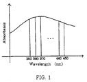
- Fig. 1 is a drawing for calculating integrated value of absorbance of the ceramics powder coated with an UV absorber.
- green sheet means, unless otherwise apparent from the context, a monolayer sheet obtained by applying the slurry mentioned in the production process described below and removing the solvent, which has not yet been exposed.
- the ceramics powder employed in the present invention is not restricted and any of the known ceramics insulation materials which can be sintered at low temperatures can be employed.
- the ceramics powder employed in the present invention include ceramics powder alone, glass-ceramics mixture and crystallized glass.
- Ceramics powders which are employed in cases where ceramics powder(s) alone is(are) employed include powders of alumina (Al2O3), zirconia (ZrO2), magnesia (MgO), beryllia (BeO), mullite (3Al2O3 ⁇ 2SiO2), cordierite (5SiO2 ⁇ 2Al2O3 ⁇ 2MgO), spinel (MgO ⁇ Al2O3), forsterite (2MgO ⁇ SiO2), anorthosite (CaO ⁇ Al2O3 ⁇ 2SiO2), celdian (BaO ⁇ Al2O3 ⁇ 2SiO2), silica (SiO2), clinoenstatite (MgO ⁇ SiO2) and aluminum nitride (AlN), and ceramics powders sintered at low temperatures. Ceramics powders having a purity of not less than 90% by weight are preferably employed.
- the aluminum nitride powder may contain a calcium-containing compound (e.g., CaC2, CaCO3, CaCN2, CaF2, CaO) or a yttrium-containing compound (e.g., Y2O3) in an amount of 0.5 - 20% by weight.
- a calcium-containing compound e.g., CaC2, CaCO3, CaCN2, CaF2, CaO
- a yttrium-containing compound e.g., Y2O3
- mixed powders containing an additive such as Y, a rare earth metal, alkaline earth metal or carbon in an amount of 0.01 - 15% by weight in terms of metal element
- mixed powders containing a carbide such as MgC2, ZrC, VC or NbC in an amount of 1 - 5% by weight in terms of the metal element and mixed powders containing an oxide such as BeO may be employed.
- More preferred added amount of these additives is 1 - 10% by weight for Y2O3 and BeO, 1 - 5% by weight for calcium oxide and not more than 1% by weight for carbon. These additives may be employed individually or in combination. By adding the additives in amounts within these ranges, the sintering property of the aluminum nitride is promoted, so that a dense sintered material having high thermal conductivity is obtained.
- glass-ceramics mixtures include mixtures of glass composition powder such as SiO2, Al2O3, CaO, B2O3, which may contain MgO and TiO2 as required, and at least one inorganic filler powder selected from the group consisting of alumina, zirconia, magnesia, beryllia, mullite, cordierite, spinel, forsterite, anorthosite, celdian, silica and aluminum nitride. More preferably, the ceramics powder is a mixture of
- glass-ceramics mixtures examples include SiO2-B2O3 glass, PbO-SiO2-Al2O3-B2O3 glass and CaO-SiO2-Al2O3-B2O3 glass to which a ceramics component such as Al2O3, quartz (SiO2), ZrO2 or cordierite is added.
- a ceramics component such as Al2O3, quartz (SiO2), ZrO2 or cordierite is added.
- SiO2 content in the glass composition powder is preferably 30 - 70% by weight. If the content is less than 30% by weight, the strength and the stability of the glass layer are decreased, and the dielectric constant and the thermal expansion coefficient are likely to be higher than the desired ranges. If the content is more than 70% by weight, the thermal expansion coefficient of the sintered substrate is high, so that it is difficult to sinter the substrate at a temperature not higher than 1000 o C.
- Al2O3 in an amount of 5 - 25% by weight. If the content is less than 5% by weight, the strength of the glass phase is decreased and it is difficult to sinter the substrate at a temperature not higher than 1000 o C. If the content is more than 25% by weight, the temperature to frit the glass composition is too high.
- CaO in an amount of 5 - 25% by weight. If the content is less than 5% by weight, the desired thermal expansion coefficient is not obtained, and it is difficult to sinter the substrate at a temperature of not higher than 1000 o C. If the content is more than 25% by weight, the dielectric constant and the thermal expansion coefficient are large, so that it is not preferred.
- MgO in an amount of 0 - 10% by weight because the control of fusion temperature is easy. If the content is more than 10% by weight, the thermal expansion coefficient of the obtained substrate is high. It is preferred to blend B2O3 in order to control the sintering temperature of the ceramics within a range of 800 - 1000 o C so as not to deteriorate electrical, mechanical and thermal characteristics such as dielectric constant, dielectric loss, strength, thermal expansion coefficient and sintered density, when the glass frit is fused at a temperature of 1300 - 1450 o C or when the content of Al2O3 is large.
- the content of B2O3 thereof is preferably 3 - 50% by weight.
- the content is less than 3% by weight, the strength of the ceramics is likely to be decreased. If the content is more than 50% by weight, the stability of the glass is decreased, rate of recrystallization by the reaction between the inorganic filler (crystalline) and the glass is large, and the glass phase oozes when the multilayer substrate is produced.
- the ceramics substrate sintered at a low temperature according to the present invention is a mixture of an amorphous glass and an inorganic filler before being sintered, depending on the type of the filler, it is assumed that the substrate may be a partially crystallized ceramics consisting of amorphous glass, ceramics and crystallized glass.
- TiO2 serves as a nucleating substance effective for forming the crystallized glass, and contained preferably in the above-described range.
- Inorganic filler powder is effective for promoting the mechanical strength of the substrate and for controlling the thermal expansion coefficient of the substrate.
- alumina, zirconia, mullite, cordierite, anorthosite and aluminum nitride have excellent effects. If the content of the inorganic filler is more than 60% by weight, the substrate is hard to be sintered, so that it is difficult to sinter the substrate at a temperature not higher than 1000 o C. If the content is less than 40% by weight, control of the thermal expansion coefficient is hardly attained and it is difficult to obtain a substrate with a low dielectric constant.
- the ceramics may be sintered at 800 - 1000 o C and the desired strength, dielectric constant, dielectric loss, thermal expansion coefficient, sintered density, volume intrinsic resistance and rate of shrinkage may be attained.
- the inorganic filler powder employed in the present invention may contain as impurities 0 - 5% by weight of Na2O, K2O, BaO, PbO, Fe2O3, Mn oxides, Cr oxides, NiO, Co oxides and the like.
- the glass composition powder may be prepared by, for example, blending SiO2, Al2O3, CaO, MgO, B2O3, TiO2 and the like which are the starting materials to a prescribed ratio, fusing the mixture at 1250 - 1450 o C, rapidly cooling the melt to prepare glass frit, and by pulverizing the glass frit to fine powder having a size of 0.5 - 3 ⁇ m.
- As the material carbonates, oxides and hydroxides with high purities can be used.
- crystallized glass examples include crystallized glass of MgO-Al2O3-SiO2 system and Li2O-Al2O3-SiO2 system.
- the crystallized glass may also be employed, which is prepared by adding B2O3 and a nucleating agent to MgO-Al2O3-SiO2 and by sintering the resultant at 900 - 1000 o C, thereby precipitating cordierite crystals so as to attain a high strength; and the crystallized glass prepared by adding B2O3 and a nucleating agent to Li2O-Al2O3-SiO2, thereby precipitating spodumene so as to attain a high strength.
- the particle size and the specific surface area of the ceramics powder employed in the present invention are selected taking the thickness of the green sheet to be produced and the rate of shrinkage by sintering into consideration, it is preferred that a particle size of 0.4 - 4 ⁇ m and a specific surface area of 0.5 - 5 m2/g be simultaneously satisfied.
- the more preferred range is 0.5 - 3 ⁇ m for the particle size and 0.6 - 3.5 m2/g for the specific surface area. If the particle size and the specific surface area are within these ranges, the UV light is sufficiently transmitted when the sheet is exposed to UV light, so that uniform via holes free from differences between the diameters of the upper portion and the lower portion of a via hole.
- the particle size of the powder is less than 0.4 ⁇ m or if the specific surface area is more than 5 m2/g, the powder is too fine and the light is scattered when the sheet is exposed, so that non-exposed regions are cured. Therefore, when the sheet is developed, via holes having a high roundness cannot be obtained. Further, the rate of shrinkage by sintering is large, so that a green sheet with a high precision cannot be obtained.
- the shape of the particles in the powder is preferably spherical which are hardly coagulated. It is preferred that the particle size distribution is sharp because the influence by scattering when the sheet is exposed to UV can be made small.
- photosensitive resin composition means a composition containing a photosensitive substance which is a photosensitive polymer and/or a photosensitive monomer, and a photopolymerization initiator. In cases where a photosensitive monomer alone is contained as the photosensitive substance, a polymer binder is further contained.
- photo-insolubilized type photosensitive substances examples include:
- photo-solubilzed type photosensitive substances examples include
- Especially preferred photosensitive substances are acrylic copolymers having carboxyl groups and ethylenically unsaturated groups in side chains.
- acrylic copolymers can be prepared by adding ethylenically unsaturated groups to side chains of an acrylic copolymer produced by copolymerizing an unsaturated carboxylic acid and an ethylenically unsaturated compound.
- unsaturated carboxylic acids include acrylic acid, methacrylic acid, itaconic acid, chrotonic acid, maleic acid, fumaric acid, vinylacetic acid and acid anhydrides thereof.
- ethylenically unsaturated compounds include methyl acrylate, methyl methacrylate, ethylacrylate, ethyl methacrylate, n-propyl acrylate, isopropyl acrylate, n-butyl acrylate, n-butyl methacrylate, sec-butyl acrylate, sec-butyl methacrylate, isobutyl acrylate, isobutyl methacrylate, tert-butyl acrylate, tert-butyl methacrylate, n-pentyl acrylate, n-pentyl methacrylate, styrene, p-methylstyrene, o-methylstyrene and m-methyls
- Examples of the ethylenically unsaturated groups in the side chains include vinyl group, allyl group, acryl group and methacryl group.
- the side chains may be attached to the acrylic copolymer by bonding an ethylenically unsaturated compound or an acrylic chloride having glycidyl group to the carboxyl groups in the acrylic copolymer by addition reaction.
- Examples of the ethylenically unsaturated compounds having glycidyl group include glycidyl acrylate, glycidyl methacrylate, allylglycidyl ether, glycidyl ethylacrylate, chrotonil glycidyl ether, chrotonic acid glycidyl ether, isochrotonic acid glycidyl ether and the like.
- Examples of the acrylic chloride compounds include acrylic chloride, methacrylic chloride, allyl chloride and the like.
- the amount of the added ethylenically unsaturated compound or the acrylic chloride is preferably 0.05 - 1 mole equivalent, more preferably 0.1 - 0.8 mole equivalent with respect to the carboxyl groups in the acrylic copolymer. If the added amount is less than 0.05 mole equivalent, the photosensitive property is not good and the formation of pattern is difficult, so that it is not preferred. If the added amount is more than 1 mole equivalent, the solubility of the non-exposed regions in the developer is decreased and the hardness of the applied film is decreased, so that it is not preferred.
- the acid value (AV) of the thus obtained acrylic polymer having carboxyl groups and ethylenically unsaturated groups in the side chains is preferably 50 - 180, more preferably 60 - 160, still more preferably 80 - 140. If the acid value is less than 50, the amount of the ethylenically unsaturated groups is large and the percentage of the carboxyl groups having photosensitivity is small, so that the allowable conditions for developing is narrowly restricted and the edges of the via holes are not clearly cut. If the acid value is more than 180, the solubility of the non-exposed regions in the developer is low. If the concentration of the developer is increased in order to overcome this problem, peeling off is observed even in the exposed regions, so that via holes may not be formed with high precision. Further, the hardness of the green sheet is decreased. The sharper the distribution of the molecular weight of the polymer having the above-mentioned preferred acid value, the better the developing properties, so that fine via holes can be formed, which is advantageous.
- photosensitive polymers also serve as polymer binders
- polymers which are not photosensitive may also be employed as the polymer binder components.
- examples thereof include polyvinyl alcohols, polyvinyl butyrals, methacrylate polymers, acrylate polymers, acrylate-methacrylate copolymers, ⁇ -methylstyrene polymers, butyl methacrylate resins and the like.
- a photosensitive monomer alone it is necessary that such non-photosensitive polymer binder be contained.
- the solvents for the non-photosensitive polymer binder include ethanol, toluene, acetone, methylethyl ketone, butanol, trichloroethylene, methylisobutyl ketone, isophorone and the like.
- the polymer binder may contain a plasticizer and/or a dispersant.
- the plasticizer dibutyl phthalate, dioctyl phthalate, polyethylene glycol, glycerin and the like may be employed.
- the dispersant sorbitan acid esters, alkylene glycols and polycarboxylic acids and the like may preferably be employed.
- compounds containing carbon-carbon unsaturated bond having photoreactivity can be used as the photoreactive substance employed in the present invention.
- specific examples of such compounds include allyl acrylate, benzyl acrylate, butoxyethyl acrylate, butoxy triethylene glycol acrylate, cyclohexyl acrylate, dicyclopentanyl acrylate, dicyclopentenyl acrylate, 2-ethylhexyl acrylate, glycerol acrylate, glycidyl acrylate, heptadecafluorodecyl acrylate, 2-hydroxyethyl acrylate, isobornyl acrylate, 2-hydroxypropyl acrylate, isodexyl acrylate, isooctyl acrylate, lauryl acrylate, 2-methoxyethyl acrylate, methoxyethylene glycol acrylate, methoxydiethylene glycol acrylate, octafluoropentyl
- the acrylic copolymer having carboxyl groups and ethylenically unsaturated groups in side chains is usually used in an amount of 0.5 - 5 times the weight of the photoreactive compound. If the amount of the acrylic copolymer is too small, the viscosity of the slurry is low and the uniformity of the dispersion in the slurry may be deteriorated. On the other hand, if the amount of the acrylic copolymer is too large, the solubility of the non-exposed regions in the developer is low.
- photopolymerization initiators employed in the present invention include benzophenone, o-benzoyl methyl benzoate, 4,4-bis(dimethylamine)benzophenone, 4,4-bis(diethylamino)benzophenone, 4,4-dichlorobenzophenone, 4-benzoyl-4-methyldiphenyl ketone, dibenzyl ketone, fluorenone, 2,2-diethoxyacetophenone, 2,2-dimethoxy-2-phenyl-2-phenylacetophenone, 2-hydroxy-2-methylpropiophenone, p-t-butyldichloroacetophenone, thioxanthone, 2-methylthioxanthone, 2-chlorothioxanthone, 2-isopropylthioxanthone, diethylthioxanthone, benzyl, benzyldimethyl ketanol, benzyl-methoxyethyl acetal, benzoin
- the photopolymerization initiator is added in an amount of 0.1 - 50%, preferably 2 - 25% by weight, based on the total of the acrylic copolymer having carboxyl groups and ethylenically unsaturated groups in the side chains and the photoreactive compound. If the amount of the photopolymerization initiator is too small, the photosensitivity is low, and if it is too large, the percentage of the remaining part in the exposed regions may be too small.
- UV absorber it is preferred to add a ultraviolet (UV) absorber to the photosensitive resin and the ceramics powder.
- UV ultraviolet
- organic dyes and inorganic powders having high UV absorbances at a wavelength of 350 - 450 nm are preferably employed.
- organic dyes having high absorbances may be used. More particularly, azo dyes, aminoketone dyes, xanthene dyes, quinoline dyes, aminoketone dyes, anthraquinone dyes and the like may be used. Since the organic dyes added as absorbers are evaporated when the substrate is sintered and do not remain in the substrate after sintering, the insulation resistance is not decreased by the absorbers, which is preferred.
- the organic dyes are added in an amount not deteriorating the bending strength, insulation resistance, dielectric constant, dielectric loss, thermal expansion coefficient and the like which are characteristic to the ceramics substrate after sintering, that is, 0.1 - 2% by weight based on the weight of the ceramics powder. If the content is less than 0.1% by weight, the effect of adding the UV absorber is small, and if the content is more than 2% by weight, the characteristics of the substrate after sintering are deteriorated, so that it is not preferred. More preferred amount of the added organic dye is 0.15 - 1% by weight.
- the inorganic powder examples include carbon; carbides such as titanium carbide (TiC), tungsten carbide (WC), zirconium carbide (ZrC), silicon carbide (SiC) and niobium carbide (NbC); borides such as titanium boride (TiB2) and zirconium boride (ZrB2); and nitrides such as titanium nitride (TiN), zirconium nitride (ZrN) and tantalum nitride (TaN).
- preferred inorganic powders are carbon and carbides because pattern can be formed sharply without blurring, and fine via holes in which the diameters of the upper portion and the lower portion are not different can be formed. Carbon is especially preferred since it is volatilized as carbon dioxide gas when the substrate is sintered in an oxygen-containing atmosphere, so that the deterioration in the insulation and dielectric characteristics of the ceramics substrate can be minimized.
- the inorganic powder may be a mixture of two or more of oxides, nitrides and carbides, it is preferred to select the inorganic powders such that the insulation and dielectric characteristics of the ceramics substrate are not deteriorated.
- Preferred amount of the inorganic powder is 0.2 - 5% by weight. If the content is less than 0.2% by weight, the effect of adding the UV absorber is small, and if it is more than 5% by weight, the characteristics of the substrate are deteriorated, so that it is not preferred. More preferred amount of the inorganic powder is 0.25 - 3% by weight.
- the UV absorber is an organic dye
- an inorganic powder such as carbon is added as the UV absorber, it is preferred to uniformly form a coating layer of carbon on the surface of each particle of the ceramics powder by CVD (chemical vapor deposition) method or by using an organic polymer.
- the integrated value of the absorbance is measured in the state of powder, and is measured for organic dyes, ceramics powders whose surfaces are coated with the organic dye or carbon, and for mixed powders of the inorganic powder having a high UV absorbance and the ceramics powder.
- absorbance is defined as follows. That is, a sample is irradiated with a light in an integrating sphere and the reflected light is collected and detected by a commercially available spectrophotometer. The light other than that detected in the integrating sphere is taken as absorbed light, and the absorbance is calculated according to the equation described below.
- the light intensity of the light reflected by the sample is expressed as (I - I0) (wherein I represents light intensity of the light impinged to the sample, and I0 represents the light intensity absorbed by the sample), and the absorbance is defined by the following equation (1) (wherein Ir represents the light intensity of the control light (i.e., the light intensity reflected by BaSO3 sample mounted on the sample table, which is the material coated on the inside of the integrating sphere)).
- Ir represents the light intensity of the control light (i.e., the light intensity reflected by BaSO3 sample mounted on the sample table, which is the material coated on the inside of the integrating sphere)).
- the absorbance is measured as follows:
- the area 1 between 350 nm and 360 nm is calculated according to the following equation, taking the shape of the section as a trapezoid: Similarly, the area 2 is calculated as follows: Similarly, the area is calculated as follows: The integrated value S of the areas of the 10 sections is calculated as follows: This area S is defined as the integrated value of absorbance at 350 - 450 nm.
- the preferred range of the above-described integrated value of absorbance is 30 - 150, more preferably 40 - 100. If the absorbance is less than 30, the UV is scattered by the powder before the UV is sufficiently transmitted to the lower portion of the green sheet, so that non-exposed regions are cured, and so via holes with high roundness may not be formed. If the absorbance is more than 150, the light is absorbed before reaching lower portion of the green sheet, so that the lower portion of the sheet cannot be photo-set. As a result, the lower portion is peeled off during developing, so that formation of via holes is difficult.
- metals such as Pb, Bi, Fe, Ni, Mn, Co and Mg and oxides thereof contained in the UV absorber react with the carboxyl groups of the photosensitive polymer contained in the slurry, so that the slurry for forming the green sheet is gelled in a short time. As a result, the slurry is agglomerated and cannot be formed into a green sheet. This is presumably caused by ion cross-linking reaction between the photosensitive polymer and the above-mentioned metals and oxides thereof.
- a compound (stabilizer) which does not give adverse affect to the photosensitive polymer as well as to the photoreactive compound, photopolymerization initiator, plasticizer and the like thereby preventing the geling of the slurry. That is, it is preferred to stabilize the photosensitive green sheet by treating the surface of the powder with a compound which forms complexes with the metal or oxide powder causing the geling reaction, or which forms salts with the functional group of the acid.
- Triazole compounds may preferably be used as the stabilizer satisfying the above-mentioned requirements.
- benzotriazole functions especially effectively.
- Hexamethylenetetramine, lithium naphthenate and the like are also effective for preventing geling.
- the surface of the powder of the metals and metal oxides in the ceramics powder and the UV absorber may be treated with benzotriazole by the following method. That is, a prescribed amount of benzotriazole is dissolved in an organic solvent such as methyl acetate, ethyl acetate, ethanol, methanol or the like, and the powder is sufficiently immersed in the solution for 1 - 24 hours. After the immersion, the mixture is naturally dried preferably at 20 - 30 o C to evaporate the solvent. By this operation, powder treated with benzotriazole is obtained.
- an organic solvent such as methyl acetate, ethyl acetate, ethanol, methanol or the like
- the rate of the stabilizer used in the present invention is preferably 0.2 - 4% by weight, more preferably 0.4 - 3% by weight. If the rate is less than 0.2% by weight, the cross-linking reaction of the polymer cannot be inhibited, so that the slurry is likely to be geled in a short time. If it is more than 4% by weight, the amount of the stabilizer is so large that it is difficult to remove the polymer binder, the photoreactive compound and the stabilizer when the green sheet is sintered in non-oxidative atmosphere, so that the characteristics of the substrate are deteriorated.
- a sensitizer thermal polymerization inhibitor, plasticizer, antioxidant, dispersant, organic or inorganic precipitation inhibitor and the like may preferably be added.
- a sensitizer may preferably be added in order to promote the photosensitivity.
- the sensitizer include 2,4-diethylthioxanthone, isopropylthioxanthone, 2,3-bis(4-diethylaminobenzal)cyclopentanone, 2,6-bis(4-dimethylaminobenzal)cyclohexanone, 2,6-bis(4-dimethylaminobenzal)-4-methylcyclohexanone, Michler's ketone, 4,4-bis(diethylamino)-benzophenone, 4,4-bis(dimethylamino)chalcone, 4,4-bis(diethylamino)chalcone, p-dimethylaminocinnamylideneindanone, p-dimethylaminobenzylideneindanone, 2-(p-dimethylaminophenylvinylene)-isonaphthothiazole, 1,3-bis(4-dimethylamin
- the amount to be added is 0.1 - 30% by weight, more preferably 0.5 - 15% by weight based on the total weight of the acrylic copolymer having carboxyl groups and ethylenically unsaturated groups in the side chains and the photoreactive compound. If the amount of the sensitizer is too small, the effect of promoting the photosensitivity is not obtained. If the amount of the sensitizer is too large, the rate of remaining portions in the exposed regions may be too small.
- a thermal polymerization inhibitor may preferably be added in order to promote the thermal stability during storage.
- the thermal polymerization inhibitor include hydroquinone, N-nitrosodiphenylamine, phenothiazine, p-t-butylcatechol, N-phenylnaphthylamine, 2,6-di-t-butyl-p-methylphenol, chloranil, pyrogallol and the like.
- the amound thereof is usually 0.1 - 20% by weight, preferably 0.5 - 10% by weight based on the total weight of the acrylic copolymer having the ethylenically unsaturated groups in the side chains and the photoreactive polymer. If the amount of the thermal polymerization inhibitor is too small, the effect of promoting the thermal stability during storage is not obtained, and if the amount of the thermal polymerization inhibitor is too large, the rate of remaining portions in the exposed regions may be too small.
- plasticizer examples include dibutyl phthalate, dioctyl phthalate, polyethylene glycol and glycerin.
- amount of the added plasticizer is not restricted, usually 0.3 - 5% by weight is preferred.
- An antioxidant may preferably be added in order to prevent oxidation of the acrylic copolymer during storage.
- Specific examples of the antioxidant include 2,6-di-t-butyl-p-cresol, butylhydroxyanisole, 2,6-di-t-4-ethylphenol, 2,2-methylene-bis-(4-methyl-6-t-butylphenol), 2,2-methylene-bis-(4-ethyl-6-t-butylphenol), 4,4-bis-(3-methyl-6-t-butylphenol), 1,1,3-tris-(2-methyl-6-t-butylphenol), 1,1,3-tris-(2-methyl-4-hydroxy-t-butylphenyl)butane, bis[3,3-bis-(4-hydroxy-3-butylphenyl)butyric acid]glycol ester, dilaurylthio dipropionate, triphenylphosphite and the like.
- the amount of the added antioxidant is usually 0.01 - 5% by weight, more preferably 0.1 - 1% by weight, based on the total weight of the ceramics powder, the acrylic copolymer having ethylenically unsaturated groups in the side chains, the photoreactive compound, the glass frit and the photopolymerization initiator. If the amount of the antioxidant is too small, the effect of preventing the oxidation of the acrylic copolymer during storage is not obtained. If the amount of the antioxidant is too large, the rate of remaining portions in the exposed regions may be too small.
- dispersant sorbitan acid esters, alkylene glycols, polycarboxylic acids and the like may preferably be employed.
- amount of the added dispersant is not restricted, it is usually 0.3 - 3% by weight.
- the precipitation inhibitor examples include ethylene oxide, propylene oxide, maleic acid partial esters, amorphous silica and the like.
- the amount of the added precipitation inhibitor is not restricted, it is usually 0.2 - 3% by weight.
- the preferred composition of the slurry for forming the ceramics green sheet according to the present invention is as follows:
- the ceramics green sheet according to the present invention may be produced by applying a slurry containing the components on a substrate, and by evaporating the solvent in cases where a solvent is contained in the slurry.
- the slurry is prepared by dissolving the acrylic copolymer having carboxyl groups and ethylenically unsaturated groups in the side chains and the photopolymerization initiator in the photoreactive monomer, and dispersing the ceramics powder and the UV absorber in this solution.
- an organic solvent in which the mixture of the acrylic copolymer, the photopolymerization initiator and the photoreactive compound can be dissolved may be added.
- this organic solvent any organic solvent which can dissolve the mixture of the acrylic copolymer having ethylenically unsaturated groups in the side chains, the photopolymerization initiator and the photoreactive compound may be employed.
- this organic solvent examples include methyl cellosolve, ethyl cellosolve, butyl cellosolve, methylethyl ketone, dioxane, acetone, cyclohexanone, cyclopentanone, isobutanol, butanol, isopropanol, tetrahydorfuran, dimethylsulfoxide, ⁇ -butyrolactone, toluene, acetone, trichloroethylene, methylisobutyl ketone and isophorone as well as mixtures thereof.
- the above-mentioned organic solvent, stabilizer, sensitizer, thermal polymerization inhibitor, plasticizer, antioxidant, dispersant, organic or inorganic precipitation inhibitor and the like are added and the resulting mixture is pulverized and mixed using a ball mill or an attriter for, say, 12 - 48 hours to prepare the slurry.
- the above-mentioned organic solvent is added as required.
- Preferred viscosity is 1000 - 5000 cps (centi poise) because if the viscosity is within this range, the thickness of the sheet can be controlled so that a sheet with uniform thickness can be obtained.
- the thus obtained slurry is continuously applied on a film such as a polyester film to a thickness of 10 - 600 ⁇ m using a doctor blade.
- the applied slurry is heated at 80 - 120 o C for 10 minutes to 1 hour to evaporate the solvent, thereby obtaining a ceramics green sheet. This sheet is then cut into an appropriate shape.
- the thickness of the ceramics green sheet according to the present invention is usually 10 - 600 ⁇ m, preferably 30 - 300 ⁇ m. If the thickness is more than 600 ⁇ m, the UV light is not well transmitted during exposure step, so that the effect of photo-setting is reduced. If the thickness is less than 10 ⁇ m, ease of handling of the green sheet is poor, and a dense substrate after the sintering is hardly obtained, so that the characteristics of the ceramics substrate are deteriorated, which are not preferred. If the thickness is within the above-mentioned range, via holes and through holes having a diameter of 0.01 - 0.2 mm can be formed without giving differences in the diameters in the upper portion and the lower portion of the via holes.
- the aspect ratio is preferably not more than 1 because the UV light is well transmitted. If the thickness of the sheet is 40 ⁇ m, via holes having a diameter of 40 ⁇ m is preferred.
- the ceramics green sheet is exposed using a conventional photomask.
- the active light source employed for the exposure UV light, electron beam, X-ray or the like may be employed. Among these, UV light is preferred.
- the source of UV light low pressure mercury lamp, high pressure mercury lamp, halogen lamp, sterilization lamp or the like may be employed. Among these, ultra high pressure mercury lamp is preferred.
- the conditions of exposure vary depending on the thickness of the green sheet and the like, it is preferred to expose the sheet using an ultra high pressure mercury lamp with an output power of 5 - 100 mW/cm2 for 1 - 30 minutes.
- the method of exposure may be appropriately selected depending on the thickness of the green sheet. In cases where the thickness of the green sheet is more than 200 ⁇ m and the aspect ratio is 0.2 - 1, it is preferred to expose both sides of the sheet because via holes having no differences in the diameters of the upper portion and lower portion can be formed.
- developing is carried out using a developer to remove the regions which were not photo-set, thereby forming a pattern of a so called negative type.
- via holes with a diameter of 0.005 - 0.2 mm may be formed with a pitch of 0.01 - 5.0 mm.
- the developing may be carried out by the immersion method or by the spray method.
- an organic solvent in which the above-described mixture of the acrylic copolymer having ethylenically unsaturated group, photoreactive compound and the photopolymerization initiator can be dissolved may be employed. To this organic solvent, water may be added in an amount not losing this dissolving ability.
- developing can be carried out using an aqueous alkali solution.
- aqueous alkali solution although aqueous alkaline metal-containing solution such as aqueous sodium hydroxide solution or aqueous calcium hydroxide solution may be employed, it is preferred to use an aqueous organic alkali solution because the alkali component can easily be removed during the sintering.
- organic alkali include tetramethylammonium hydroxide, trimethylbenzylammonium hydroxide, monoethanolamine, diethanolamine and the like.
- the concentration of the aqueous alkali solution is usually 0.01 - 3% by weight, more preferably 0.1 - 2% by weight. If the alkali concentration is too low, non-exposed regions may not be removed, and if the alkali concentration is too high, peeling off of the exposed regions may occur and the sheet may be corroded, which are not preferred.
- conductors for connecting the lines in different layers are formed by using a electroconductive paste.
- the electroconductive paste used herein is the same as, or different from that used for forming the circuit pattern, that is, electroconductive paste containing copper, silver, silver-palladium, tungsten, molybdenum or gold.
- the embedding of the electroconductive paste is carried out by employing screen printing, squeezing, dispenser or a roller.
- the embedding of the electroconductive paste in the via holes in the green sheet is carried out repeatedly sheet by sheet.
- a prescribed pattern of conductor, dielectric material or a resist is formed on the surface of the sheet.
- Guide holes are formed by the same method as that for forming the via holes.
- a requisite number of sheets are laminated using the guide holes and the laminate is subjected to thermocompression bonding at a temperature of 90 - 130 o C under a pressure of 50 - 200 kg/cm2 to obtain a multilayer sheet.
- the sheet is then sintered in a sintering furnace to obtain a multilayer ceramics green sheet having conductors in the via holes.
- the atmosphere and the temperature employed in the sintering varies depending on the types of the ceramics substrate and the conductors.
- the sheet is kept usually at 850 - 1000 o C for several hours to sinter the insulation layer.
- the substrate is sintered usually at 1600 o C for several hours.
- the substrate is sintered in a reducing atmosphere containing a neutral gas such as nitrogen, or hydrogen.
- a neutral gas such as nitrogen, or hydrogen.
- Any atmosphere which enables oxidation and evaporation of the organic compounds such as acrylic copolymer having ethylenically unsaturated groups in the side chains, the photoreactive polymerizable compound, the stabilizer and the like contained in the photosensitive green sheet during the sintering may be employed.
- the sintering may be carried out in a controlled atmosphere containing 3 - 50 ppm of oxygen and the balance of a neutral gas such as nitrogen or argon, or water vapor.
- the sintering may be performed by first keeping the substrate at a temperature of 300 - 550 o C for 30 minutes to several hours to completely oxidizing and evaporating the organic binder, and then at 800 - 1600 o C for several hours to prepare a ceramics multilayer substrate.
- the amount of the carbon remaining in the multilayer substrate after sintering be not more than 250 ppm. If the amount of the residual carbon is large, problems that the porosity of the multilayer substrate is decreased, the strength is decreased, the dielectric constant is increased, the dielectric loss is increased, the leak current is increased, and that insulation resistance is decreased may be brought about.
- the amount of the residual carbon is more preferably not more than 100 ppm, still more preferably not more than 50 ppm.
- the solvent and the polymer binder were mixed and the mixture was heated to 120 o C under stirring to uniformly dissolve the entire polymer binder.
- the solution was then cooled to room temperature and the initiator was added and dissolved.
- the resulting solution was filtered through a 400-mesh filter.
- the photoreactive compound and the ceramics powder were added to the above-described organic vehicle to attain a prescribed composition.
- the mixture was mixed using an attriter for 24 hours in wet condition to obtain a slurry.
- the viscosity of the prepared slurry determined using a Brookfield viscometer (type: PVDV-II+) at a revolution of 50 rpm was 1500 cps.
- the compositions of the slurries are shown in Tables 1, 2 and 3.
- Molding of the green sheets was carried out by the doctor blade method in an UV-cut room.
- the gap between the polyester carrier film and the blade was 0.6 - 0.8 mm and the molding rate was 1 m/min.
- the thicknesses of the obtained green sheets are shown in Tables 1, 2 and 3.
- Each of the green sheets prepared above was cut into square pieces sizing 150 mm x 150 mm, and each of the square pieces was heated at 90 o C for 40 minutes to evaporate the solvent.
- a chromium mask having 3000 via holes with a diameter of 40 ⁇ m, the sheet was exposed to UV light emitted from an ultra high pressure mercury lamp with an output power of 50 mW/cm2, which lamp was arranged above the mask.
- the sheet was then immersed in 1 wt% aqueous monoethanolamine solution kept at 25 o C to develop the sheet and the via holes which were not photo-set were washed off with water using a spray.
- the thus obtained 10-ply laminates were baked in the air at 500 o C for 3 hours to evaporate the binder, and then sintered at 900 - 1000 o C for 0.5 hours to obtain multilayer ceramics substrates.
- the green sheets having W as the conductor were baked in an atmosphere of H2 (hydrogen) gas and N2 (nitrogen) gas at 500 o C for 5 hours to remove the binder and then sintered at 1600 o C for 0.5 hours to obtain multilayer ceramics substrates.
- the green sheet containing a photo-setting resin via holes are formed by photolithography, so that the produced ceramics multilayer substrate can have fine via holes, which is advantageous for compaction and high densification of the devices.
- a screen for forming via holes is not necessary, and the green sheets are aligned by self-alignment. Therefore, unlike the conventional green sheets, the green sheets according to the present invention are not shifted when they are laminated.
- a mixture of 53% of alumina powder (1) or cordierite powder (2), 10% of acrylate resin, 24% of toluene, 8% of isopropyl alcohol and 5% of dibutyl phthalate was mixed using an attriter and green sheets having a thickness of 100 ⁇ m were prepared from the mixtures by the doctor blade method under the same conditions as mentioned above. Then 2000 via holes having a diameter of 200 ⁇ m were formed by punch press method using a metal mold.
- conductors were formed using W metal paste for the green sheet containing alumina or using the silver-palladium alloy paste for the green sheet containing cordierite powder. The green sheets were then laminated and sintered under the same conditions as in F described above.
- the solvent and the polymer binder were mixed and the mixture was heated to 120 o C under stirring to uniformly dissolve the entire polymer binder.
- the solution was then cooled to room temperature and the photopolymerization initiator, plasticizer and the organic binder were added and dissolved.
- the resulting solution was filtered through a 400-mesh filter.
- the monomer and the aluminum nitride powder were added to the above-described organic vehicle to attain a prescribed composition.
- the mixture was mixed using an attriter for 24 hours in wet condition to obtain a slurry.
- the viscosity of the prepared slurry determined by using a Brookfield viscometer (type: PVDV-II+) at a revolution of 50 rpm was 1700 cps.
- the compositions of the slurries are shown in Tables 4 and 5.
- Molding of the green sheets was carried out by the doctor blade method in an UV-cut room.
- the gap between the polyester carrier film and the blade was 0.40 mm and the feed speed was 2.5 m/min.
- the thicknesses of the obtained green sheets are shown in Tables 4 and 5.
- Each of the green sheets prepared above was cut into square pieces sizing 120 mm x 120 mm, and each of the square pieces was heated at 90 o C for 40 minutes to evaporate the solvent.
- a chromium mask having 3000 via holes with a diameter of 40 ⁇ m, the sheet was exposed to UV light emitted from an ultra high pressure mercury lamp with an output power of 50 mW/cm2, which lamp was arranged above the mask.
- the sheet was then immersed in 1 wt% aqueous monoethanolamine solution kept at 25 o C to develop the sheet and the via holes which were not photo-set were washed off with water using a spray.
- thick W paste was embedded by the screen printing method to form conductors for connecting lines of different layers.
- a prescribed circuit pattern is printed using the same thick paste as mentioned above.
- Ten green sheets on which the W conductor was printed were laminated using a guide hole, and the laminate was subjected to thermocompression bonding at 80 o C under a pressure of 90 kg/cm2 for 30 minutes to obtain multilayer ceramics green sheets each of which has 10 layers.
- the green sheet containing a photo-setting resin via holes are formed by photolithography, so that the produced ceramics multilayer substrate can have fine via holes, which is advantageous for compaction and high densification of the devices.
- a screen for forming via holes is not necessary, and the green sheets are aligned by self-alignment. Therefore, unlike the conventional green sheets, the green sheets according to the present invention are not shifted when they are laminated.
- conductors were formed using W metal paste, and ten green sheets were laminated.
- the laminates were sintered under the same conditions as in F described above.
- the solvent and the polymer binder were mixed and the mixture was heated to 120 o C under stirring to uniformly dissolve the entire polymer binder.
- the solution was then cooled to room temperature and the photopolymerization initiator was added and dissolved.
- the resulting solution was filtered through a 400-mesh filter to obtain an organic vehicle.
- the photoreactive compound, the ceramics powder (ceramics powder encapsulated with the organic dye), Floren dispersant, the sensitizer and the plasticizer were added to the above-described organic vehicle to attain a prescribed composition.
- the mixture was mixed using an attriter for 24 hours in wet condition.
- the resultant was defoamed in a vacuum stirrer for 24 hours to obtain a slurry.
- compositions of the slurries are shown in Tables 6 and 7.
- Molding of the green sheets was carried out by the doctor blade method in an UV-cut room.
- the gap between the polyester carrier film and the blade was 0.7 - 1.0 mm and the molding rate was 1 m/min.
- the thicknesses of the obtained green sheets are shown in Tables 6 and 7.
- Each of the green sheets prepared above was cut into square pieces sizing 150 mm x 150 mm, and each of the square pieces was heated at 90 o C for 40 minutes to evaporate the solvent.
- a chromium mask having 3000 via holes with a diameter of 60 ⁇ m, the sheet was exposed to UV light emitted from an ultra high pressure mercury lamp with an output power of 500 mJ/cm2, which lamp was arranged above the mask.
- the sheet was then immersed in 0.5 wt% aqueous monoethanolamine solution kept at 25 o C to develop the sheet and the via holes which were not photo-set were washed off with water using a spray.
- thick paste of tungsten when ceramics powder (1) was used
- silver-palladium alloy when ceramics powder (2) or (3) was used
- screen printing method to form conductors for connecting lines in the different layers.
- a prescribed circuit pattern was printed using the same thick paste as mentioned above.
- the green sheets having the silver-palladium alloy as the conductor were baked in the air at 500 o C for 3 hours to evaporate the binder, and then sintered at 900 - 1000 o C for 1.5 hours to obtain multilayer ceramics substrates.
- the green sheets having tungsten as the conductor were baked in an atmosphere of H2 (hydrogen) gas and N2 (nitrogen) gas at 500 o C for 5 minutes to evaporate the binder and then sintered at 1600 o C for 1.5 hours to obtain multilayer ceramics substrates.
- the green sheet containing a photo-setting resin via holes are formed by photolithography, so that the produced ceramics multilayer substrate can have fine via holes, which is advantageous for compaction and high densification of the devices.
- a screen for forming via holes is not necessary, and the green sheets are aligned by self-alignment. Therefore, unlike the conventional green sheets, the green sheets according to the present invention are not shifted when they are laminated. Since uniform via holes can be formed by photo-setting and the via holes are fine, pores are not formed in the via holes, so that cutting of the lines was not observed at all. As a result, a high reliability was obtained. Further, when compared with the conventional multilayer substrates having via holes with diameters 4 - 8 times larger than those of the substrates according to the present invention, rate of propagation of signals was largely decreased.
- the ceramics green sheet according to the present invention may suitably be employed for forming sintered ceramics substrates, especially those on which semiconductor devices connected one another are mounted with a high density, especially for forming multilayer ceramics substrates.
Landscapes
- Chemical & Material Sciences (AREA)
- Engineering & Computer Science (AREA)
- Ceramic Engineering (AREA)
- Manufacturing & Machinery (AREA)
- Structural Engineering (AREA)
- Organic Chemistry (AREA)
- Materials Engineering (AREA)
- Inorganic Chemistry (AREA)
- Chemical Kinetics & Catalysis (AREA)
- Physics & Mathematics (AREA)
- General Physics & Mathematics (AREA)
- Compositions Of Oxide Ceramics (AREA)
- Production Of Multi-Layered Print Wiring Board (AREA)
Abstract
Applications Claiming Priority (7)
| Application Number | Priority Date | Filing Date | Title |
|---|---|---|---|
| JP180077/92 | 1992-07-07 | ||
| JP18007792A JP3312389B2 (ja) | 1992-07-07 | 1992-07-07 | セラミックス・グリーンシートおよびその現像方法 |
| JP18007792 | 1992-07-07 | ||
| JP3832593 | 1993-02-26 | ||
| JP38325/93 | 1993-02-26 | ||
| JP3832593 | 1993-02-26 | ||
| PCT/JP1993/000862 WO1994001377A1 (fr) | 1992-07-07 | 1993-06-25 | Feuille ceramique crue |
Publications (3)
| Publication Number | Publication Date |
|---|---|
| EP0602252A1 true EP0602252A1 (fr) | 1994-06-22 |
| EP0602252A4 EP0602252A4 (fr) | 1994-11-23 |
| EP0602252B1 EP0602252B1 (fr) | 2000-08-30 |
Family
ID=26377542
Family Applications (1)
| Application Number | Title | Priority Date | Filing Date |
|---|---|---|---|
| EP93913579A Expired - Lifetime EP0602252B1 (fr) | 1992-07-07 | 1993-06-25 | Feuille ceramique crue |
Country Status (3)
| Country | Link |
|---|---|
| EP (1) | EP0602252B1 (fr) |
| DE (1) | DE69329329T2 (fr) |
| WO (1) | WO1994001377A1 (fr) |
Cited By (9)
| Publication number | Priority date | Publication date | Assignee | Title |
|---|---|---|---|---|
| EP0719529A1 (fr) * | 1994-12-26 | 1996-07-03 | Kyocera Corporation | Implant poreux en céramique et son procédé de préparation |
| EP0845445A4 (fr) * | 1996-06-17 | 1999-10-27 | Toray Industries | Feuille crue de ceramique photosensible, emballage ceramique, et procede de fabrication |
| FR2788268A1 (fr) * | 1999-01-11 | 2000-07-13 | Transfert De Technologies Cera | Composition ceramique pateuse pour l'alimentation d'une machine de prototypage rapide et procede de fabrication |
| FR2835828A1 (fr) * | 2002-02-08 | 2003-08-15 | Ct De Transfert De Technologie | Procede et composition pour la fabrication de pieces ceramiques par stereo-lithophotographie et application au domaine dentaire |
| FR2835827A1 (fr) * | 2002-02-08 | 2003-08-15 | Ct De Transfert De Technologie | Procede et composition pour fabriquer une piece en matiere ceramique par prototypage rapide et pieces obtenues |
| EP1594921A4 (fr) * | 2003-01-10 | 2006-03-29 | Korea Res Inst Chem Tech | Composition photopolymerisable et film photopolymerisable fabrique a partir de ladite composition |
| EP1840102A3 (fr) * | 2006-03-28 | 2007-11-14 | Ngk Insulators, Ltd. | Feuille en céramique verte et un procédé pour fabriquer la même |
| EP1840103A3 (fr) * | 2006-03-28 | 2007-12-05 | Ngk Insulators, Ltd. | Procédé de production d'un corps dense fritté de céramique en forme d'une feuille |
| CN108484176A (zh) * | 2018-05-24 | 2018-09-04 | 宁夏艾森达新材料科技有限公司 | 一种高温共烧陶瓷用氮化铝生瓷片的制备方法 |
Families Citing this family (3)
| Publication number | Priority date | Publication date | Assignee | Title |
|---|---|---|---|---|
| DE10130893A1 (de) * | 2001-06-27 | 2003-01-16 | Siemens Ag | Glaskeramik, keramischer Grünkörper und monolithischer keramischer Mehrschichtkörper mit der Glaskeramik |
| CN111825333B (zh) * | 2019-04-15 | 2021-08-27 | 西安交通大学 | 一种玻璃浆料及其制备方法和3d打印玻璃器件的方法 |
| CN112930027A (zh) * | 2021-01-18 | 2021-06-08 | 成都宏科电子科技有限公司 | 白色氧化铝陶瓷基板金属化的填孔钨浆料及其制备方法 |
Family Cites Families (10)
| Publication number | Priority date | Publication date | Assignee | Title |
|---|---|---|---|---|
| US4536535A (en) * | 1983-06-07 | 1985-08-20 | E. I. Du Pont De Nemours And Company | Castable ceramic compositions |
| JPS60211898A (ja) * | 1984-04-05 | 1985-10-24 | 日本電気株式会社 | 多層配線基板の製造方法 |
| JPS60250686A (ja) * | 1984-05-25 | 1985-12-11 | 日本碍子株式会社 | セラミツク配線基板の製造方法 |
| US4566186A (en) * | 1984-06-29 | 1986-01-28 | Tektronix, Inc. | Multilayer interconnect circuitry using photoimageable dielectric |
| JPS61274399A (ja) * | 1985-05-29 | 1986-12-04 | 株式会社ノリタケカンパニーリミテド | 多層セラミック基板用組成物および多層セラミック基板の製造方法 |
| JPS6364953A (ja) * | 1986-09-05 | 1988-03-23 | 工業技術院長 | セラミツクスシ−ト用組成物、及びセラミツクスシ−トの製造法 |
| JPH01232797A (ja) | 1988-03-11 | 1989-09-18 | Narumi China Corp | セラミック多層回路基板 |
| EP0357063A3 (fr) * | 1988-09-02 | 1991-05-02 | E.I. Du Pont De Nemours And Company | Compositions de couchage céramiques photosensibles |
| JPH02141458A (ja) | 1988-11-24 | 1990-05-30 | Noritake Co Ltd | 低温焼成セラミック多層基板およびその製造方法 |
| JPH089644B2 (ja) * | 1990-02-19 | 1996-01-31 | 三菱レイヨン株式会社 | 光重合性組成物 |
-
1993
- 1993-06-25 WO PCT/JP1993/000862 patent/WO1994001377A1/fr not_active Ceased
- 1993-06-25 EP EP93913579A patent/EP0602252B1/fr not_active Expired - Lifetime
- 1993-06-25 DE DE69329329T patent/DE69329329T2/de not_active Expired - Lifetime
Cited By (12)
| Publication number | Priority date | Publication date | Assignee | Title |
|---|---|---|---|---|
| EP0719529A1 (fr) * | 1994-12-26 | 1996-07-03 | Kyocera Corporation | Implant poreux en céramique et son procédé de préparation |
| EP0845445A4 (fr) * | 1996-06-17 | 1999-10-27 | Toray Industries | Feuille crue de ceramique photosensible, emballage ceramique, et procede de fabrication |
| US6159322A (en) * | 1996-06-17 | 2000-12-12 | Toray Industries, Inc. | Photosensitive ceramic green sheet, ceramic package, and process for producing the same |
| FR2788268A1 (fr) * | 1999-01-11 | 2000-07-13 | Transfert De Technologies Cera | Composition ceramique pateuse pour l'alimentation d'une machine de prototypage rapide et procede de fabrication |
| WO2000042471A1 (fr) * | 1999-01-11 | 2000-07-20 | Centre De Transfert De Technologies Ceramiques (C.T.T.C.) | Composition de pate ceramique et procede de prototypage |
| FR2835828A1 (fr) * | 2002-02-08 | 2003-08-15 | Ct De Transfert De Technologie | Procede et composition pour la fabrication de pieces ceramiques par stereo-lithophotographie et application au domaine dentaire |
| FR2835827A1 (fr) * | 2002-02-08 | 2003-08-15 | Ct De Transfert De Technologie | Procede et composition pour fabriquer une piece en matiere ceramique par prototypage rapide et pieces obtenues |
| WO2003066326A3 (fr) * | 2002-02-08 | 2004-03-25 | Ct De Transfert De Technologie | Procede et composition pour la fabrication de pieces ceramiques par stereo-lithophotographie et application au domaine dentaire |
| EP1594921A4 (fr) * | 2003-01-10 | 2006-03-29 | Korea Res Inst Chem Tech | Composition photopolymerisable et film photopolymerisable fabrique a partir de ladite composition |
| EP1840102A3 (fr) * | 2006-03-28 | 2007-11-14 | Ngk Insulators, Ltd. | Feuille en céramique verte et un procédé pour fabriquer la même |
| EP1840103A3 (fr) * | 2006-03-28 | 2007-12-05 | Ngk Insulators, Ltd. | Procédé de production d'un corps dense fritté de céramique en forme d'une feuille |
| CN108484176A (zh) * | 2018-05-24 | 2018-09-04 | 宁夏艾森达新材料科技有限公司 | 一种高温共烧陶瓷用氮化铝生瓷片的制备方法 |
Also Published As
| Publication number | Publication date |
|---|---|
| WO1994001377A1 (fr) | 1994-01-20 |
| EP0602252B1 (fr) | 2000-08-30 |
| DE69329329D1 (de) | 2000-10-05 |
| EP0602252A4 (fr) | 1994-11-23 |
| DE69329329T2 (de) | 2001-03-29 |
Similar Documents
| Publication | Publication Date | Title |
|---|---|---|
| US6004705A (en) | Photosensitive ceramics green sheet | |
| EP0845445B1 (fr) | Feuille crue de ceramique photosensible, emballage ceramique, procede de fabrication et utilisation | |
| JPH05271576A (ja) | 感光性導電ペースト | |
| EP0602252B1 (fr) | Feuille ceramique crue | |
| JP3668978B2 (ja) | 感光性絶縁ペースト | |
| JP3360378B2 (ja) | セラミックス・グリーンシート上にパターンを形成する方法 | |
| JP3324259B2 (ja) | セラミックス・グリーンシート | |
| JPH0834096A (ja) | セラミックス・グリーンシートおよびセラミックス・グリーンシート上にパターンを形成する方法 | |
| JPH1075039A (ja) | パターン形成したセラミックスグリーンシートの製造法 | |
| JPH10265270A (ja) | 感光性セラミック組成物 | |
| JPH10279364A (ja) | セラミックス・グリーンシート | |
| JP3312389B2 (ja) | セラミックス・グリーンシートおよびその現像方法 | |
| JPH05287221A (ja) | 感光性導電ペースト | |
| KR100803476B1 (ko) | 기판 적용 ltcc 감광성 테이프에 유용한 전도체 조성물 | |
| JP3128910B2 (ja) | セラミックス・グリ−ンシ−ト | |
| JP4501460B2 (ja) | 感光性セラミックス組成物 | |
| JP2007197312A (ja) | 拘束シートおよび焼結体の製造方法 | |
| JP2007086268A (ja) | 感光性シート | |
| JP4760087B2 (ja) | セラミックス基板の製造方法 | |
| KR100786517B1 (ko) | 유전 시이트의 적용 방법 및 그에 사용되는 감광성 유전조성물 및 테이프 | |
| JPH05311097A (ja) | 感光性絶縁ペ−スト | |
| JP4507873B2 (ja) | 感光性セラミックス組成物 | |
| JPH09142940A (ja) | セラミックグリーンシートおよびパターン形成されたセラミックグリーンシートの製造方法 | |
| JPH10274843A (ja) | セラミックス・グリーンシート及びそのビアホール形成方法 | |
| JPH10279363A (ja) | セラミックス・グリーンシート |
Legal Events
| Date | Code | Title | Description |
|---|---|---|---|
| PUAI | Public reference made under article 153(3) epc to a published international application that has entered the european phase |
Free format text: ORIGINAL CODE: 0009012 |
|
| 17P | Request for examination filed |
Effective date: 19940328 |
|
| AK | Designated contracting states |
Kind code of ref document: A1 Designated state(s): AT BE CH DE DK ES FR GB GR IE IT LI LU MC NL PT SE |
|
| A4 | Supplementary search report drawn up and despatched | ||
| AK | Designated contracting states |
Kind code of ref document: A4 Designated state(s): AT BE CH DE DK ES FR GB GR IE IT LI LU MC NL PT SE |
|
| RBV | Designated contracting states (corrected) |
Designated state(s): DE FR GB NL |
|
| 17Q | First examination report despatched |
Effective date: 19960819 |
|
| GRAG | Despatch of communication of intention to grant |
Free format text: ORIGINAL CODE: EPIDOS AGRA |
|
| GRAG | Despatch of communication of intention to grant |
Free format text: ORIGINAL CODE: EPIDOS AGRA |
|
| GRAH | Despatch of communication of intention to grant a patent |
Free format text: ORIGINAL CODE: EPIDOS IGRA |
|
| GRAH | Despatch of communication of intention to grant a patent |
Free format text: ORIGINAL CODE: EPIDOS IGRA |
|
| GRAA | (expected) grant |
Free format text: ORIGINAL CODE: 0009210 |
|
| AK | Designated contracting states |
Kind code of ref document: B1 Designated state(s): DE FR GB NL |
|
| REF | Corresponds to: |
Ref document number: 69329329 Country of ref document: DE Date of ref document: 20001005 |
|
| ET | Fr: translation filed | ||
| PLBE | No opposition filed within time limit |
Free format text: ORIGINAL CODE: 0009261 |
|
| STAA | Information on the status of an ep patent application or granted ep patent |
Free format text: STATUS: NO OPPOSITION FILED WITHIN TIME LIMIT |
|
| 26N | No opposition filed | ||
| REG | Reference to a national code |
Ref country code: GB Ref legal event code: IF02 |
|
| PGFP | Annual fee paid to national office [announced via postgrant information from national office to epo] |
Ref country code: NL Payment date: 20090615 Year of fee payment: 17 |
|
| PGFP | Annual fee paid to national office [announced via postgrant information from national office to epo] |
Ref country code: GB Payment date: 20090624 Year of fee payment: 17 |
|
| PGFP | Annual fee paid to national office [announced via postgrant information from national office to epo] |
Ref country code: DE Payment date: 20100625 Year of fee payment: 18 |
|
| REG | Reference to a national code |
Ref country code: NL Ref legal event code: V1 Effective date: 20110101 |
|
| GBPC | Gb: european patent ceased through non-payment of renewal fee |
Effective date: 20100625 |
|
| REG | Reference to a national code |
Ref country code: FR Ref legal event code: ST Effective date: 20110228 |
|
| PG25 | Lapsed in a contracting state [announced via postgrant information from national office to epo] |
Ref country code: FR Free format text: LAPSE BECAUSE OF NON-PAYMENT OF DUE FEES Effective date: 20100630 Ref country code: NL Free format text: LAPSE BECAUSE OF NON-PAYMENT OF DUE FEES Effective date: 20110101 |
|
| PG25 | Lapsed in a contracting state [announced via postgrant information from national office to epo] |
Ref country code: GB Free format text: LAPSE BECAUSE OF NON-PAYMENT OF DUE FEES Effective date: 20100625 |
|
| REG | Reference to a national code |
Ref country code: DE Ref legal event code: R119 Ref document number: 69329329 Country of ref document: DE Effective date: 20120103 |
|
| PG25 | Lapsed in a contracting state [announced via postgrant information from national office to epo] |
Ref country code: DE Free format text: LAPSE BECAUSE OF NON-PAYMENT OF DUE FEES Effective date: 20120103 |
|
| PGFP | Annual fee paid to national office [announced via postgrant information from national office to epo] |
Ref country code: FR Payment date: 20090611 Year of fee payment: 17 |