EP0609149A2 - Drucker nach der Sublimationsart und photographisches Papier dafür - Google Patents
Drucker nach der Sublimationsart und photographisches Papier dafür Download PDFInfo
- Publication number
- EP0609149A2 EP0609149A2 EP94400173A EP94400173A EP0609149A2 EP 0609149 A2 EP0609149 A2 EP 0609149A2 EP 94400173 A EP94400173 A EP 94400173A EP 94400173 A EP94400173 A EP 94400173A EP 0609149 A2 EP0609149 A2 EP 0609149A2
- Authority
- EP
- European Patent Office
- Prior art keywords
- dye
- sublimation type
- set forth
- type printer
- vaporizing
- Prior art date
- Legal status (The legal status is an assumption and is not a legal conclusion. Google has not performed a legal analysis and makes no representation as to the accuracy of the status listed.)
- Granted
Links
Images





Classifications
-
- B—PERFORMING OPERATIONS; TRANSPORTING
- B41—PRINTING; LINING MACHINES; TYPEWRITERS; STAMPS
- B41J—TYPEWRITERS; SELECTIVE PRINTING MECHANISMS, i.e. MECHANISMS PRINTING OTHERWISE THAN FROM A FORME; CORRECTION OF TYPOGRAPHICAL ERRORS
- B41J2/00—Typewriters or selective printing mechanisms characterised by the printing or marking process for which they are designed
- B41J2/005—Typewriters or selective printing mechanisms characterised by the printing or marking process for which they are designed characterised by bringing liquid or particles selectively into contact with a printing material
Definitions
- the present invention relates generally to a printer such as a laser, sublimation type color video printer for making a thermal imprint of still video or television images etc., on photographic paper using sublimation type dyes, or the like.
- Sublimation type printers have been proposed for applications requiring impression of video and or television images on photographic paper or the like. Such types of printers are favored since they require no thermal head or ink ribbon, and may operate on low levels of electricity. In addition they may be substantially small in size and low in cost.
- a laser sublimation type color video printer (hereinbelow: printer) 1 receives a cassette 3 containing photographic paper 50'.
- the printer 1 includes a planar base 4 for printing on a chassis 2, the chassis 2 is covered by an outer case 2a.
- a discharge slot 2b is provided in the front face of the outer case 2a and, behind the discharge slot 2b, a feed roller 6a is provided, driven by a motor 5.
- the feed roller 6a contacts a pressure driven roller 6b such that the photographic paper 50' may be discharged from the printer 1 between the rollers 6a, 6b.
- the printer 1 further includes a head driving circuit substrate 7 connected to a head assembly 10 which is disposed on the plane base 4. The substrate 7 and the head assembly 10 are connected by a flexible wire harness 7a.
- the head assembly is provided with dye tanks (11Y (yellow), 11M (magenta), 11C (cyan)) 11, accommodating solid sublimation type dyes 12 (12Y, 12M, 12C), of each of the above-noted primary colors.
- the dyes 12 may be in solidified powder form, for example.
- a dye passage 15 (15Y, 15M, 15C) connects between each of the tanks 11 and vaporizing sections 17 over a wear-resistant protective layer 13 of the head assembly 10.
- the protective layer 13 is made of a high strength material and is located at the lower side of a head base 14 made of glass, transparent ceramic, or the like.
- the dye passage 15 allows passage of the dye 12 as liquefied dye 12' after heating by heating units 16 (Fig.
- the liquefied dye 12' from each of the dye passages 15 is brought to the vaporizing sections 17.
- a laser beam source (i.e. a semiconductor laser) 18 is mounted above the head base 14 on a mounting stand 19. Vaporizing pores 17a of the vaporizing sections 17 are irradiated by laser beams L generated at the laser sources 18.
- each of the vaporizing sections 17 comprise a plurality of pores 17a in each of which an upper transparent insulation layer 20' is provided at a lower side of the head base 14 atop a light-heat conversion layer 21' and a lower adhesion layer 23'.
- the light-heat conversion layer 21' absorbs light from the laser beam L and converts same into heat, while the adhesion layer 23' has glass beads 22' inset therein for carrying vaporized dye 12'' vaporized by the laser beam L at each vaporizing pore 17a.
- the transparent insulation layer 20' is made of a clear PET resin, for example, and the light-heat conversion layer 21' is formed by applying a binder and fine carbon particles to the lower side of the transparent insulation layer 20'.
- Glass beads 22' are selected with a size from 5 - 10 microns in diameter.
- the heating units 16 are active to allow the solid dye 12 to liquefy and be maintained as liquefied dye 12' and to flow down to be held at the glass beads 22' to be converted to vaporized dye 12'' according to irradiation of the vaporizing section 17 by the laser beam L.
- Sheets of the photographic paper 50' are drawn singly out of the cassette 3 between the plane base 4 and the head assembly 10 to be fed to the rollers 6a, 6b.
- the head assembly 10 is biased against the plane base 4 under a light load (approx. 50g) by load applying springs 9, as seen in Fig. 14.
- a plurality of laser sources 18 for each of the colors Yellow, Magenta and Cyan (hereinbelow: Y, M, C) are aligned at the head assembly 10 in three rows to perform heating and liquefaction respectively for the dyes 12Y, 12M and 12C.
- the dyes 12 in each of the dye tanks 11Y, 11M and 11C are heated to the melting point by the heating elements 16 and quantitatively supplied to each pore 17a of the plurality of vaporizing portions 17Y, 17M, 17C via the passages 15.
- the dye 12 may move from the tanks 11 to the glass beads 22' via a simple capillary effect.
- a signal is sent to the head portion for each one line of an image to be printed and for each single color laser beams L are generated accordingly at the laser sources 18 which are then converted to heat at the respective light-heat converting layers 21' such that an appropriate amount of liquefied dye of each color Y, M and C, is held at the glass beads 22' to be vaporized by the applied heat to be imprinted successively in the order of Y, M and C to a dye receiving layer 50'a at the surface of the photographic paper 50'.
- the imprinted photographic paper 50' is then fed between the protective layer and the plane base 4 to result in a finished color print.
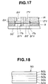
- Fig. 18 shows a conventional type of photographic paper utilized in such a laser sublimation type printer 1 as described above.
- the photo paper 50' is a laminate comprising of a dye receiving surface layer 50'a, a light-absorbing layer 50'e, a polypropylene layer 50'b, a base paper layer 50'c and a polypropylene layer 50'd.
- the light-absorbing layer 50'e of the photographic paper 50' absorbs a portion of the light from the laser source 18 and converts it to heat which heats the dye receiving surface layer 50a to aid the vaporized dye 12'' in forming a thermal imprint on the dye receiving surface layer 50a.
- the head portion 10 of such a laser sublimation type printer 1 may have a elongate pore 17b formed along one side thereof.
- This elongate pore 17b allows irradiation of the photographic paper by a second laser Lo for removing discoloration caused by the presence of a light absorbing agent present in the light absorbing layer 50'e of the photographic paper 50'. That is, the agent present in the light absorbing layer 50'e gives the photographic paper 50' a pale tint, irradiation by the laser beam Lo whitens the light absorbing agent to produce a sharper more attractive image on the photographic paper 50'.
- the dyes 12 are brought to the glass beads 22' by a capillary phenomenon, and the sizes of the glass beads 22' may vary slightly, it is difficult to assure that a uniform amount of dye is brought to each vaporizing section 17 and for this reason also, uniformity of color is difficult to assure.
- the light-heat converting layer 21' itself is subject to destruction due to generated heat and the PET resin material of the insulation layer 21' is apt to incur thermal damage at around 140°C.
- the area of the light-heat converting layer 21' is larger than an irradiation area of one spot of light from the laser source 18 and an imprint area of the dye 12 and an energy efficiency of heat imprinting is degraded as excessive heat is lost.
- the glass beads 22' are used as the holding layer for retaining the liquefied dye 12' prior to vaporizing, an adhesion layer 23' must be provided an the problem of heat resistance is incurred. That is, while the supply of liquefied dye 12' to the glass beads 22' depends on the diffusion speed of the dye 12 itself, it is impossible to supply the dye 12 to the glass beads 22' at significantly high speeds since the speed of supply varies according to operating influences and the influence of the respective laser sources 18.
- the vaporizing sections 17 must be provided in rows and spaced about 30 microns apart. This limits material which can be used for the protective layer 13 and incurs high production costs in manufacture for etching and adhesion technique, etc. It is also noted that, according to the conventional structure, a separate, dedicated laser source is required for operating in the elongate pore 17b for irradiating the light-absorbing agent.
- a laser sublimation type printer comprising: a laser sublimation type printer, comprising: solidified dye accommodating tank containing solid form sublimation type dye and mounted on an upper side of a head portion of the printer; a vaporizing section including a vaporizing pore which is open on a lower side thereof through a protective layer which contacts a surface of photographic paper on which printing is to be carried out; a liquefied dye accommodating passage defined in the head portion and communicating an outlet of the dye tank with an interior space of the vaporizing pore; heating means provided proximate the liquefied dye accommodating passage for melting the solid form sublimation type dye and maintaining the dye in a liquid state; light-heat converting means projected into the vaporizing pore, a lower side thereof for receiving liquid dye introduced to the vaporizing pore from the liquefied dye accommodating passage, an area of the lower side of the light-heat converting means being limited to an area of the photographic paper capable of being covered by a
- printer laser sublimation type color video printer
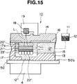
- Fig. 1 shows a cross-sectional view of a head portion 10 of the laser sublimation type printer 1 of the first embodiment.
- the construction of the head portion 10 is generally the same as that of the conventional arrangement, including dye tanks 11Y, 11M and 11Y accommodating sublimating dyes 12Y, 12M and 12C and having passages 15 formed between a head base 14 made of glass, transparent ceramic, or the like, and a protective layer 13 made of a high-strength material.
- heating elements 16 which may be relatively elongated compared with the related art as shown in Fig. 1.
- the heating elements 16 are comprised of electrical resistors according to the present embodiment, and a plurality of laser sources 18, such as semiconductor laser chips which are mounted on the head base 14 via stands 19 so as to position the laser sources 18 over the vaporizing pores 17a of vaporizing sections 17.
- a non-return valve 24 is provided between each of the solid dye 12 accommodating dye tanks 11 and the liquid dye 12' accommodating dye passages 15, as well as a vibrating unit 25 acting as a dye pressurizing and supply means.
- the vibrating unit 25 is constituted by a bimorph, piezo-element or the like and works to urge dye 12 from the dye tanks 11 toward the vaporizing sections 17 communicating with each of the liquid dye passages 15.
- the non-return valve functions so as to close an outlet 23 of the dye tank 11 during activation of the vibrating unit 25 and opens the outlet 23 when no pressurizing (vibration of the vibrating unit 25) takes place.
- the vaporizing sections 17 of the present embodiment is provided with a heat resistant, light transmitting base 20 which simultaneously exhibits high heat resistance, with good light transmission and insulative characteristics.
- a light-heat conversion layer 21 is provided for receiving the light of the laser beam L through the light transmitting base 20 and converting same to heat.
- a liquid dye holding layer 22 is provided for retaining liquefied dye introduced to the vaporizing section 17 from the liquid dye passage 15 to be vaporized by heat generated according to irradiation of the light-heat conversion layer 21 by the laser beam L.
- the heat resistant, light transmitting base 20 is formed of a transparent film material applied on the head base 14 and having a heat resistance of not less than 180°C, thermal conductivity of not more than 1w/m°C, near infrared transmittance of not less than 85% for a thickness of 10 microns, a specific heat of not more than 2J/g°C and a density of not more than 3g/cm3.
- the light-heat conversion layer 21 is formed as a metallic thin film of nickel-cobalt alloy having no binder, for example, applied by vapor deposition, sputtering, or the like and having an infrared transmittance of not less than 0.9% for a thickness of not more than 1 micron, a specific heat of not more than 0.5 J/g°C, thermal conductivity of not less than 20w/m°C and a density of not more than 20g/cm3.
- the area of the light-heat conversion layer 21 is limited to an imprint area S of the vaporized dye 12'' (Fig. 1).
- the liquid dye holding layer 22 is a metallic thin film formed directly on the light-heat conversion layer 21.
- the metallic film of the liquid dye holding layer 22 is formed into a mesh shape by etching processing or the like so as to retain the liquefied dye 12'.
- the printer 1 according to the present invention is capable of supplying liquefied dye 12' to the pores 17a of the vaporizing sections in uniform amounts due to the mesh structure of the liquid dye holding layer 22 and at high speed due to the provision of the heating elements 16 and the vibrating units 25. Further, provision of the non-return valve 24 prevents liquefied dye from being introduced to the dye tanks 11 and assists the vibrating units 25 in applying low pressure to the liquefied dye which, in combination with the heating elements and the capillary phenomenon, allows the printer to print at higher speed with greater color uniformity.
- the light-heat conversion layer 21 is formed of a metallic thin film, it is possible to improve the heat resistance of the light-heat conversion layer 21 to allow continuous use thereof. Since the thickness of the light-heat conversion layer is held low and the area thereof is limited to the imprint area S of the vaporized dye 12'', the heating capacity can be held small and the area surrounding the light-heat conversion layer 21 can in effect be insulated by the liquefied dye 12' to enhance the overall thermal efficiency of the arrangement.
- the heat resistant, light transmitting base 20 is highly heat resistant, it is able to withstand continuous use. Also, the thermal conductivity can be made large while thermal diffusion is rapidly performed in over the entire area thereof even when the light energy distribution from the laser beam L is non-uniform such as a gaussian distribution, for example. Thus, uniform temperature distribution can be realized. Further, because the light-heat conversion layer 21 to the is applied directly to the heat resistant, light transmitting base 20 by sputtering or the like, it is possible to suitably alter and optimize the light absorption ratio and the thermal conductivity by increasing or decreasing a supply amount of oxygen during deposition.
- the liquid dye holding layer 22 is formed as a metallic thin film directly over the light-heat conversion layer 21, no adhesive layer is required and heat efficiency is improved while a size and complexity of the structure is reduced. Also, the thin metallic film of the liquid dye holding layer 22 is processed into a mesh shape and, by varying the pitch and depth of the mesh during processing, it can be assured that a suitable amount of liquefied dye 12' may be always and certainly held. Because the liquid dye holding layer 22 is formed of a metallic thin film, the heat resistance thereof is considerably improved and thus will not deteriorate under heavy or continuous use.
- the dyes 12 in each of the dye tanks 11Y, 11M and 11C are heated to the melting point by the heating elements 16Y, 16M and 16C and quantitatively supplied to each pore 17a of the plurality of vaporizing sections 17 via the dye passages 15.
- the liquefied dye 12' may move from the tanks 11 to the vaporizing pores 17a smoothly and at high speed due to the provision of the vibrating units 25 and the heating elements 16.
- a signal is sent to the head portion for each one line of an image to be printed and for each single color.
- Laser beams L are generated accordingly at the laser sources 18 which are then converted to heat at the respective light-heat converting layers 21 such that an appropriate amount of liquefied dye of each color Y, M and C, is held at the dye holding layer 22 of each of the vaporizing pores 17a to be vaporized by applied heat converted from the light of the laser beam L by the light-heat conversion layer 21 to be imprinted successively in the order of Y, M and C to a dye receiving layer 50a at the surface of the photographic paper 50.
- the imprinted photographic paper 50 is then fed between the protective layer 13 and the plane base 4 to output a finished color print.
- a cross-sectional view of a head portion 10 of a printer 1 according to a second preferred embodiment is shown.
- the structure of the head portion 10 is substantially identical to that of the previous embodiment, however, according to the present embodiment, within the vaporizing pore 17a, a heat resistant, light transmitting base 30 is formed on a lower surface of the head base 14.
- the heat resistant, light transmitting base 30 also has insulative properties and may be of aromatic polyamide (aramide), for example.
- a light-heat conversion layer 31 is formed as a metallic thin film of a nickel-cobalt alloy, for example, applied by vapor deposition, sputtering, or the like.
- the area of the light-heat conversion layer 31 is limited to an imprint area S of the vaporized dye 12''.
- a timing chart is shown accompanying an enlarged cross-sectional view of the light-heat conversion layer 31 and the heat resistant, light transmitting base 30.
- the material of the heat resistant, light transmitting base 30 is selected for thermal expansion characteristics as shown in Fig. 3.
- the material of the heat resistant, light transmitting base 30 is caused to expand rapidly (Fig.
- ⁇ 1 represents a diameter of an irradiated spot ( ⁇ 1 100 ⁇ m)
- the vaporized dyes 12''Y, 12''M and 12''C are imprinted on the surface 50a of the photographic paper 50 in the order given, such that layers of dye of a single color are printed respectively one over the other while the photographic paper 50 is fed between the plane base 4 and the protecting layer 13 resulting in a full color printed image.
- the area of the light-heat conversion layer 31 is limited to the imprint area S of the vaporized dye 12'', thus the heating capacity can be held small and the area surrounding the light-heat conversion layer 21 is insulated by the liquefied dye 12' to enhance the overall thermal efficiency of the arrangement.
- the heat resistant, light transmitting base 30 is made of aromatic polyamide, the heat resistance is enhanced so that the heat resistant, light transmitting base 30 may endure continuous use.
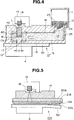
- Fig. 4 shows a third embodiment of a laser sublimation type color video printer 1 according to the invention.
- the structure of the head portion 10 of the present embodiment is substantially the same as that of the previously described embodiments, including a non-return valve 24 and a vibrating unit 25.
- an optical fiber 40 is provided in the vaporizing pore 17a for functioning as a light transmitting means for the laser beam L. According to this, the laser beam L is surely led into the vaporizing pore 17a without leakage, thus energy efficiency is assured.
- a light-heat conversion layer 41 is formed of a metallic thin film of nickel-cobalt alloy, for example, applied by vapor deposition, sputtering, or the like.
- each of the vaporizing pores 17a is surrounded by an insulating material 42 to increase a heating efficiency and durability of the head portion 10.
- the area of the light-heat conversion layer 41 is limited to the imprint area S of vaporized dye 12'', thus the heating capacity can be held small and the area surrounding the light-heat conversion layer 41 is insulated by the insulating material 42 and the liquefied dye 12' to prevent heat loss to the area surrounding the vaporizing pore 17a, thus a vaporization ratio of the sublimation type dyes 12 is enhanced.
- thermal conductivity is high and thermal diffusion at the light-heat conversion layer 41 is rapidly performed providing uniform temperature distribution even if non-uniform or gaussian distribution of light is received from the laser source 18.
- thermal conductivity is high and thermal diffusion at the light-heat conversion layer 41 is rapidly performed providing uniform temperature distribution even if non-uniform or gaussian distribution of light is received from the laser source 18.
- printer according to the third embodiment functions substantially as described in connection with the previous two embodiments.
- Fig. 5 shows a fourth embodiment of a laser sublimation type printer 1 according to the invention.
- liquefied dye 12' is supplied to light-heat conversion means (21, 31, 41) to effect printing.
- light-heat conversion means 21, 31, 41
- the head portion 10 of the printer may comprise a head base 14 of glass, transparent ceramic, or the like, a light transmission layer 20A of a heat resistant light transmitting material (aromatic polyamide resin may also be used), a light-heat conversion layer 21A which may comprise a metallic thin film of nickel-cobalt alloy, for example, applied by vapor deposition, sputtering or the like.
- the light-heat conversion layer 21A is selectively irradiated by the laser beam L from the laser source 18 for vaporizing dyes 12 contained in the dye ribbon 12A, for effecting printing.
- the structure of the head portion 10 of the printer 1 may be greatly simplified.
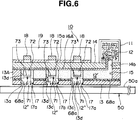
- Fig. 6 shows a longitudinal cross-section of the head portion 10 according to a fifth embodiment of the invention.
- the mounting stand 19 mounts a plurality of laser sources 18.
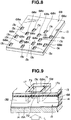
- the materials and construction of the head portion 10 including the head base 14, the protective layer 13 and a spacer 13A provided between the head base 14 and the protective layer 13, will be described in detail referring to Figs. 6 - 10.
- Fig. 7 an inverted, cut-away perspective view of the protective layer 13 and spacer 13A is shown.
- the function of the protective layer 13 is to contamination of the vaporizing pores 17a by dust, dirt, etc. , while contacting the surface 50a of the photographic paper 50 under light pressure.
- the protective layer may be formed of glass, ceramic or tantalum, a metallic material having good thermal conductivity with excellent heat and wear resistance.
- the protective layer 13 is formed with a plurality of quadratic, prism-shaped openings 13c which serve as a lower side of the vaporizing pores 17a (for example, a pitch between adjacent openings may be established at 100 ⁇ m).
- the openings 13c may be formed by etching processing, or the like.
- the spacer 13A may be formed of glass, ceramic, polyethylene resin, metallic tantalum, or the like.
- the function of the spacer 13A is to balance or adjust the melting temperature of each of the liquefied dyes 12' and the temperature of a dye receiving surface layer 50a of the photographic paper 50, by transferring heat to the protective layer 13.
- the spacer 13A is formed with a plurality of quadratic prism-shaped openings 13d which also serve as part of the vaporizing pores 17a and, grooved openings 13B corresponding to the dye passages 15 extending from the side of each of the dye tanks 11 to the opposite side of the head base 14 to intercommunicate each of the vaporizing pores 17a respectively.
- a liquid dye pooling layer 68 is set between the protective layer 13 and the spacer 13A.
- the liquid dye pooling layer 68 is formed of a fluorine or silicon type transparent resin material which is heat resistant and chemically stable.
- the liquid dye pooling layer 68 is active to prevent liquefied dye 12' from leaking through the material of the protective layer and adhering to the surface 50a of the photographic paper 50.
- the liquid dye pooling layer 68 is formed with a plurality of quadratic openings 68a for forming the vaporizing pores 17a. It will be noted that the protective layer 13, the spacer 13A and the liquid dye pooling layer 68 are laminated together via an adhesive (not shown) having heat resistance and light-transmitting characteristics.
- the head base 14 is formed to be as thin as possible and may be of a material such as glass, transparent ceramic or the like having a substantially high melting point, no heat molding characteristics, good light transmittance and low thermal conductivity.
- a reinforcement plate 14a between the head base 14 and the laser mounting stand 19.
- a connection pore 14b is formed for communicating with the dye passages 15.
- the head base 14, the reinforcing plate 14a and the laser mounting stand 19 are also joined together and to the protective layer 13, the spacer 13A and the liquid dye pooling layer 68 by adhesive having heat resistance and light-transmitting characteristics.
- a heating plate 16A is provided rather that the embedded resistors 16 of the previous embodiments.
- the heating plate 16A may be formed of a carbon or silicon compound, for example, capable of generating heat at 50°C - 300°C according to application thereto of an electric current, thus liquefying the sublimation type dyes 12 and maintaining them in a warm, liquid state.
- end portions of the heating plate 16A are bent perpendicularly upward so as to extend into a lower portion of each of the dye tanks 11 so as to facilitate melting of the powder form dye 12 and promote the flow of liquid dye 12'' and also to prevent clogging of the powder form solid dye 12 at the outlet of the dye tanks 11.
- each of the heating plates 16A is arranged so as to surround the vaporizing sections 17 of the head portion 10 and thus is active to warm the spacer 13A, the protective layer 13 and also serves to heat the dye receiving surface 50a of the photographic paper 50.
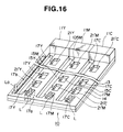
- the dye passages 15 are capillary tubes defined collectively by the head base 14, the grooved openings 13B of the spacer 13A, and the protective layer 13. While the vaporizing pores 17a are collectively formed by the openings 13c of the protective layer 13, openings 68a of the dye pooling layer 68 and openings 13d of the spacer 13A for forming the vaporizing pores 17a according to lamination with a heat resistant, light transmitting adhesive. Each of the vaporizing pores 17a constitutes minimum dot unit, for imprinting a single picture element.
- the vaporizing pores 17a are arranged in a so-called checkered pattern using the dye passages 15 as a boundary area between groupings of vaporizing pores 17a for vaporizing section 17Y (yellow), vaporizing section 17M (magenta) and vaporizing section 17C (cyan). According to this arrangement, a pitch between the vaporizing sections 17Y, 17M and 17C can be reduced to a spacing of not more than 30 ⁇ m, which allows high image resolution to be achieved.
- a light heat conversion layer 71 is provided which is associated respectively with a laser source 18.
- the light heat conversion layer 71 may be of any of the configurations noted in connection with the previous embodiments and may include a light transmission component 72 for effecting conversion of the light of the laser beam L to heat for vaporizing a suitable amount of liquefied dye 12' present in the vaporizing pore 17a.
- the empty space of the vaporizing pore 17a acts as a dye pool for always storing a constant amount of liquefied dye 12' and, according to capillary pressure present in the vaporizing pores 17a, an air space A is formed in each of the vaporizing pores 17a between the light-heat conversion layer 71 and the surface 50a of the photographic paper 50.
- the presence of the air space A provides additional insulating characteristics for further enhancing printer performance.
- the heating plate 16A is provided on a lower side of the dye passage 15 between the liquid dye pooling layer 68 and the protective layer 14 for increased heating efficiency for facilitating the flow of liquefied dye 12' from the dye tanks 11 to the vaporizing pore 17a.
- the heating plate 16A is provided with a plurality of quadratic openings 16b which act in combination with the openings 13c of the protective layer 13, openings 68a of the dye pooling layer 68 and openings 13d of the spacer 13A for forming the vaporizing pores 17a according to lamination with a heat resistant, light transmitting adhesive.
- an end portion of the heating element 26 is arranged so as to extend into the dye tank 11 for promoting melting of the powder form solid dye 12 and smooth flow of liquefied dye 12'.
- the sixth embodiment is substantially identical to the previously described fifth embodiment.
- Fig. 11 shows a cross-sectional view of photographic paper 50 adapted for optimal performance with the printing method effected by the printer 1 according to the invention.
- the photographic paper 50 is comprised of a dye receiving surface 50a formed of a cellulose type resin or the like capable of absorbing the vaporized (sublimation type) dyes 12'', a polypropylene layer 50b under the surface 50a having strong heat resistance and good moisture repellent characteristics, a base paper layer 50c and a polypropylene layer 50d for structurally balancing the polypropylene layer 50b to prevent warping of the photographic paper 50.
- These four layers are laminated together for forming a photographic paper 50 which will yield high-quality results with the printing arrangement of the invention.
- Fig. 12 shows a mounting structure 60 of a laser sublimation type printer 1 which movably mounts a pair of head portions 10, 10 which may be constructed according to any of the above-described embodiments.
- the head portions 10, 10 are respectively mounted on a threaded shaft 62 via arm portions 65, 65 each having a threaded opening 66 provided therethrough for receiving the shaft 62.
- the head portions 10 are capable of reciprocating movement in a head feeding direction, indicated by an arrow Z, which is perpendicular to a paper feed direction, indicated by an arrow X in Fig. 12.
- a head receiving roller 64 is disposed under the head portions 10, 10 such that photographic paper 50 is interposed between the head portions 10, 10 and the head receiving roller 64 during printing.
- the mounting structure 60 enables the head portions to print two lines at one pass, which may be of different colors, for example.
- Each of the head portions are connected to a control portion (not shown) of the printer 1 via a flexible wire harness 67.
- the fifth and sixth embodiments include a heating plate 16A, a portion of which is extended into an outlet of each of the dye tanks 11, it is possible, according to the invention to additionally provide the head portions 10 of these embodiments with the non-return valve 24 and the vibrating units 25 of the first to third embodiments for further enhancing the speed and efficiency of the laser sublimation type printer 1.
- the heating plate 16A of the fifth and sixth embodiments may also be preferably introduced to the structure of the head portions 10 of the first three embodiments.
- the structure of the head portion is simple, comprising the head base 14, the spacer 13A and the protective layer 13, even when the minimum tolerances are provided for spacing of the vaporizing pores 17a and the vaporizing sections 17Y - 17C, according to etching processing or the like, the options for selection of materials for manufacturing the head portion are many, allowing additional cost reduction to be contemplated.
- an insulated environment is provided for vaporization of the sublimating liquefied dye 12' defined by the interior of the vaporizing pore 17a, the pool of liquefied dye 12' therein and the surface 50a of the photographic paper 50.
- foreign matter such as dust etc.
- a minimum amount of energy may be expended for vaporizing the liquefied dyes 12' since excess heat will not escape into the surface 50a of the photographic paper 50. Accordingly, an energy efficiency of the printer 1 is improved.
- the light transmission component 72 i.e. heat resistant, light-transmitting layers 20, 30
- the light-heat conversion layer 71 i .e. light-heat conversion layers 21, 31, 41
- photographic paper such as described hereinabove in relation to Fig. 11 may be utilized in which no light-absorbing layer need be provided, thus irradiation of the paper by a dedicated laser beam Lo for whitening the light-absorbing agent is not necessary and the apparatus may be simplified while the cost of the photographic paper may also be reduced.
Landscapes
- Electronic Switches (AREA)
- Thermal Transfer Or Thermal Recording In General (AREA)
Applications Claiming Priority (6)
| Application Number | Priority Date | Filing Date | Title |
|---|---|---|---|
| JP1124193 | 1993-01-27 | ||
| JP1124193A JPH06218956A (ja) | 1993-01-27 | 1993-01-27 | レーザ昇華型プリンタ |
| JP11241/93 | 1993-01-27 | ||
| JP1210693 | 1993-01-28 | ||
| JP12106/93 | 1993-01-28 | ||
| JP1210693A JP3243867B2 (ja) | 1993-01-28 | 1993-01-28 | 昇華型プリンタ |
Publications (3)
| Publication Number | Publication Date |
|---|---|
| EP0609149A2 true EP0609149A2 (de) | 1994-08-03 |
| EP0609149A3 EP0609149A3 (de) | 1994-09-14 |
| EP0609149B1 EP0609149B1 (de) | 2000-06-07 |
Family
ID=26346656
Family Applications (1)
| Application Number | Title | Priority Date | Filing Date |
|---|---|---|---|
| EP94400173A Expired - Lifetime EP0609149B1 (de) | 1993-01-27 | 1994-01-27 | Drucker nach der Sublimationsart und photographisches Papier dafür |
Country Status (3)
| Country | Link |
|---|---|
| US (1) | US5561451A (de) |
| EP (1) | EP0609149B1 (de) |
| DE (1) | DE69424808T2 (de) |
Cited By (4)
| Publication number | Priority date | Publication date | Assignee | Title |
|---|---|---|---|---|
| EP0700787A1 (de) * | 1994-09-09 | 1996-03-13 | Sony Corporation | Verfahren und Vorrichtung zur Aufzeichnung |
| EP0680828A3 (de) * | 1994-05-06 | 1998-09-16 | Sony Corporation | Aufzeichnungskopf und Aufzeichnungsgerät |
| US5917530A (en) * | 1993-07-16 | 1999-06-29 | Imperial Chemical Industries Plc | Dye diffusion thermal transfer printing |
| CN111867843A (zh) * | 2018-03-22 | 2020-10-30 | 柯尼卡美能达株式会社 | 喷墨头及其制造方法 |
Families Citing this family (4)
| Publication number | Priority date | Publication date | Assignee | Title |
|---|---|---|---|---|
| KR940010649A (ko) * | 1992-10-14 | 1994-05-26 | 오오가 노리오 | 인쇄장치와 감광지 |
| JPH07164656A (ja) * | 1993-10-22 | 1995-06-27 | Sony Corp | 記録部構造及び記録装置 |
| US5828391A (en) * | 1994-03-08 | 1998-10-27 | Sony Corporation | Thermal transfer recording device |
| JP3575103B2 (ja) * | 1995-02-17 | 2004-10-13 | ソニー株式会社 | 記録方法 |
Family Cites Families (7)
| Publication number | Priority date | Publication date | Assignee | Title |
|---|---|---|---|---|
| US3798365A (en) * | 1969-07-14 | 1974-03-19 | P Johnson | Recording method and apparatus utilizing light energy to move record forming material onto a record medium |
| DE3702643A1 (de) * | 1986-02-10 | 1987-08-13 | Toshiba Kawasaki Kk | Tintenstrahlschreiber sowie schreibkopf und schreibkopfkassette dafuer |
| JPH059698Y2 (de) * | 1986-11-27 | 1993-03-10 | ||
| US5023625A (en) * | 1988-08-10 | 1991-06-11 | Hewlett-Packard Company | Ink flow control system and method for an ink jet printer |
| ATE215118T1 (de) * | 1990-09-29 | 2002-04-15 | Canon Kk | Verfahren und vorrichtung zur tintenstrahlaufzeichnung |
| US5170178A (en) * | 1991-03-26 | 1992-12-08 | Minolta Camera Kabushiki Kaisha | Thermal transfer recording apparatus |
| KR940010649A (ko) * | 1992-10-14 | 1994-05-26 | 오오가 노리오 | 인쇄장치와 감광지 |
-
1994
- 1994-01-21 US US08/183,836 patent/US5561451A/en not_active Expired - Fee Related
- 1994-01-27 DE DE69424808T patent/DE69424808T2/de not_active Expired - Fee Related
- 1994-01-27 EP EP94400173A patent/EP0609149B1/de not_active Expired - Lifetime
Cited By (5)
| Publication number | Priority date | Publication date | Assignee | Title |
|---|---|---|---|---|
| US5917530A (en) * | 1993-07-16 | 1999-06-29 | Imperial Chemical Industries Plc | Dye diffusion thermal transfer printing |
| EP0680828A3 (de) * | 1994-05-06 | 1998-09-16 | Sony Corporation | Aufzeichnungskopf und Aufzeichnungsgerät |
| EP0700787A1 (de) * | 1994-09-09 | 1996-03-13 | Sony Corporation | Verfahren und Vorrichtung zur Aufzeichnung |
| US5847732A (en) * | 1994-09-09 | 1998-12-08 | Sony Corporation | Recording device |
| CN111867843A (zh) * | 2018-03-22 | 2020-10-30 | 柯尼卡美能达株式会社 | 喷墨头及其制造方法 |
Also Published As
| Publication number | Publication date |
|---|---|
| DE69424808D1 (de) | 2000-07-13 |
| DE69424808T2 (de) | 2000-12-21 |
| EP0609149B1 (de) | 2000-06-07 |
| US5561451A (en) | 1996-10-01 |
| EP0609149A3 (de) | 1994-09-14 |
Similar Documents
| Publication | Publication Date | Title |
|---|---|---|
| US5521140A (en) | Recording unit structure and recording device | |
| EP0609149B1 (de) | Drucker nach der Sublimationsart und photographisches Papier dafür | |
| KR20070094518A (ko) | 써멀 헤드 및 이것을 구비한 프린터 장치 | |
| EP0700787B1 (de) | Verfahren und Vorrichtung zur Aufzeichnung | |
| US7372476B2 (en) | Thermal printing device, method for printing an image using said printing device and system for printing an image | |
| JPH11198421A (ja) | 画像形成方法及び画像形成装置 | |
| KR100325401B1 (ko) | 기록헤드및기록장치 | |
| JP3243867B2 (ja) | 昇華型プリンタ | |
| JP3428598B2 (ja) | 光吸収体 | |
| JPH06218956A (ja) | レーザ昇華型プリンタ | |
| JPH07108711A (ja) | レーザ昇華型プリンタ | |
| JP3364913B2 (ja) | 染料気化型プリンタ | |
| JP3364912B2 (ja) | 染料気化式プリンタ | |
| JPH08258301A (ja) | 記録装置及びその製造方法 | |
| JPH0768804A (ja) | 記録装置 | |
| JPH08216442A (ja) | 記録装置 | |
| JPH0768802A (ja) | 記録材気化又は昇華装置、記録方法及び記録装置 | |
| JPH0848048A (ja) | 記録ヘッド部構造及び記録装置、並びにこれらの製造方法 | |
| JPH06179265A (ja) | 昇華型プリンタ | |
| JPH08336992A (ja) | 記録装置及びその製造方法 | |
| JPH08156433A (ja) | 記録装置 | |
| JPH06198922A (ja) | プリンタ装置 | |
| JPH10235911A (ja) | 溶融型熱転写印刷装置 | |
| JPH0752446A (ja) | レーザ気化型プリンタ | |
| JPH08258298A (ja) | 記録方法及び記録装置 |
Legal Events
| Date | Code | Title | Description |
|---|---|---|---|
| PUAI | Public reference made under article 153(3) epc to a published international application that has entered the european phase |
Free format text: ORIGINAL CODE: 0009012 |
|
| PUAL | Search report despatched |
Free format text: ORIGINAL CODE: 0009013 |
|
| AK | Designated contracting states |
Kind code of ref document: A2 Designated state(s): DE FR GB |
|
| AK | Designated contracting states |
Kind code of ref document: A3 Designated state(s): DE FR GB |
|
| 17P | Request for examination filed |
Effective date: 19950221 |
|
| 17Q | First examination report despatched |
Effective date: 19960131 |
|
| GRAG | Despatch of communication of intention to grant |
Free format text: ORIGINAL CODE: EPIDOS AGRA |
|
| GRAG | Despatch of communication of intention to grant |
Free format text: ORIGINAL CODE: EPIDOS AGRA |
|
| GRAG | Despatch of communication of intention to grant |
Free format text: ORIGINAL CODE: EPIDOS AGRA |
|
| GRAH | Despatch of communication of intention to grant a patent |
Free format text: ORIGINAL CODE: EPIDOS IGRA |
|
| GRAH | Despatch of communication of intention to grant a patent |
Free format text: ORIGINAL CODE: EPIDOS IGRA |
|
| GRAA | (expected) grant |
Free format text: ORIGINAL CODE: 0009210 |
|
| AK | Designated contracting states |
Kind code of ref document: B1 Designated state(s): DE FR GB |
|
| REF | Corresponds to: |
Ref document number: 69424808 Country of ref document: DE Date of ref document: 20000713 |
|
| ET | Fr: translation filed | ||
| PLBE | No opposition filed within time limit |
Free format text: ORIGINAL CODE: 0009261 |
|
| STAA | Information on the status of an ep patent application or granted ep patent |
Free format text: STATUS: NO OPPOSITION FILED WITHIN TIME LIMIT |
|
| 26N | No opposition filed | ||
| REG | Reference to a national code |
Ref country code: GB Ref legal event code: IF02 |
|
| PGFP | Annual fee paid to national office [announced via postgrant information from national office to epo] |
Ref country code: FR Payment date: 20020110 Year of fee payment: 9 |
|
| PGFP | Annual fee paid to national office [announced via postgrant information from national office to epo] |
Ref country code: GB Payment date: 20020130 Year of fee payment: 9 |
|
| PGFP | Annual fee paid to national office [announced via postgrant information from national office to epo] |
Ref country code: DE Payment date: 20020227 Year of fee payment: 9 |
|
| PG25 | Lapsed in a contracting state [announced via postgrant information from national office to epo] |
Ref country code: GB Free format text: LAPSE BECAUSE OF NON-PAYMENT OF DUE FEES Effective date: 20030127 |
|
| PG25 | Lapsed in a contracting state [announced via postgrant information from national office to epo] |
Ref country code: DE Free format text: LAPSE BECAUSE OF NON-PAYMENT OF DUE FEES Effective date: 20030801 |
|
| GBPC | Gb: european patent ceased through non-payment of renewal fee | ||
| PG25 | Lapsed in a contracting state [announced via postgrant information from national office to epo] |
Ref country code: FR Free format text: LAPSE BECAUSE OF NON-PAYMENT OF DUE FEES Effective date: 20030930 |
|
| REG | Reference to a national code |
Ref country code: FR Ref legal event code: ST |