EP0632251B1 - Verformungsüberwachungssystem für Ausrichtvorrichtung - Google Patents
Verformungsüberwachungssystem für Ausrichtvorrichtung Download PDFInfo
- Publication number
- EP0632251B1 EP0632251B1 EP19940110113 EP94110113A EP0632251B1 EP 0632251 B1 EP0632251 B1 EP 0632251B1 EP 19940110113 EP19940110113 EP 19940110113 EP 94110113 A EP94110113 A EP 94110113A EP 0632251 B1 EP0632251 B1 EP 0632251B1
- Authority
- EP
- European Patent Office
- Prior art keywords
- jig tool
- fluid
- monitoring system
- float
- displacement sensor
- Prior art date
- Legal status (The legal status is an assumption and is not a legal conclusion. Google has not performed a legal analysis and makes no representation as to the accuracy of the status listed.)
- Expired - Lifetime
Links
Images


Classifications
-
- G—PHYSICS
- G01—MEASURING; TESTING
- G01C—MEASURING DISTANCES, LEVELS OR BEARINGS; SURVEYING; NAVIGATION; GYROSCOPIC INSTRUMENTS; PHOTOGRAMMETRY OR VIDEOGRAMMETRY
- G01C5/00—Measuring height; Measuring distances transverse to line of sight; Levelling between separated points; Surveyors' levels
- G01C5/04—Hydrostatic levelling, i.e. by flexibly interconnected liquid containers at separated points
Definitions
- the present invention relates to a level surface monitoring system for a large jig tool for monitoring a fact as to whether any differential subsiding is caused by age deterioration or age change to a ground on which a large jig tool is settled and any deformation over an allowable range is caused to the large jig tool.
- the deformation of the large jig tool due to the ground subsiding is amended or corrected by adjusting the leg portions thereof by means of, for example, screw jacks mounted to the respective leg portions through a periodical inspection, for example, once a year, in which the deformation of the large jig tool is measured by using a measuring machine such as transit.
- a surface level monitoring system having the features of the preamble of claim 1 is known from US-A-3,949,484.
- US-A-4,894,924 discloses a surface level monitoring system having one reference liquid-level sensor means and at least one displacement sensor means.
- the float of this system is connected with a vertical stem which guides the float allowing movement of the float only in the vertical direction.
- the stem further transfers the float movement to a magnetic transducer generating the float signal.
- Patent Abstracts of Japan to JP 60146119 discloses an optical sensor for a liquid-level detection system to define the position of a float having a reflecting surface floating on the liquid surface.
- An object of the present invention is to substantially eliminate defects or problems encountered in the prior art described above and to provide a level surface monitoring system for a large jig tool capable of monitoring, in a real time, a deformation of the large jig tool with high performance.
- the communicating tube may be provided with a plurality of vertical tubes having end openings and positioned at portions corresponding to the measuring areas of the respective displacement sensors.
- the floats are disposed in the respective vertical tubes.
- the displacement sensors are preferably constructed by light sensors and, in such case, the float is provided with a light reflecting member mounted on an upper surface thereof.
- the supporting members may have jack mechanisms for maintaining all the surface levels of the supporting members constant.
- a temperature sensor may be further disposed in association with the large jig tool for calculating a thermal expansion coefficient of the large jig tool in accordance with a material constituting the large jig tool and for correcting an output from the displacement sensor in accordance with the thermal expansion coefficient.
- a plurality of displacement sensors are mounted to a plurality of supporting members of a large jig tool, respectively, each of the displacement sensors having a measuring area, a communicating tube is disposed on the base and in which a fluid fills and is provided with a plurality of openings at portions corresponding to the measuring areas of the respective displacement sensors, and a signal processing unit operatively connected to the displacement sensors to process signals transmitted therefrom and to monitor a surface level of the large jig tool.
- the entire fluid height in the communicating tube is made the same as reference level, and the displacements with respect to this reference level are measured and processed in a real time by the processing unit, which carries out the data processing and numerical value analysis at high speed, thus effectively and precisely monitoring the surface level of the large jig tool.
- the location of the float in the fluid surface corresponding to the measuring areas of the displacement sensors can effectively suppress the flow of the fluid or vibration thereof causing measurement error and make uniform the condition of the surface level, thus improving the measurement precision.
- the measurement can be done in non-contact method, and the provision of the light reflecting member on the upper surface of the float can improve the resolving power in the measurement and S/N ratio as well.
- Fig. 1 is a perspective view of a level surface monitoring system for a large jig tool according to one embodiment of the present invention.
- a large jig tool 1 is composed of a large number of shaft-shaped members assembled in a lattice structure so as to provide a frame shape.
- the large jig tool 1 has, for example, a longitudinal length of about 12m and a height of about 7m.
- two large jig tools 1 are illustrated, and the large jig tools 1 are settled on a flat surface base such as flat floor or ground each through a plurality of leg members 1a as tool body supporting members.
- a displacement sensor 3 such as light sensor is mounted to each of the leg members 1a and each of the displacement sensors has own measuring area.
- a communicating tube 4 is horizontally disposed in association with the displacement sensors 3 and a plurality of vertical tubes 5 is connected to the communicating tube 4 to stand vertically at portions corresponding to the measuring areas of the displacement sensors 3, respectively.
- a fluid such as water or oil fills in the communicating tube and a fluid amount is adjusted so that a fluid level is near an upper end opening portion of each of the vertical tubes 5 when they are disposed in usable attitudes.
- a reservoir tank 6, in which a predetermined amount of fluid is stored, is connected to one end of a communicating tube 4a so as to make up the fluid therein for the compensation for natural evaporation or leakage of the fluid.
- a plurality of communicating tubes 4 are also disposed in the manner such as shown in Fig. 1 and these communicating tubes 4 are also connected through another communicating tube 4a.
- the respective displacement sensors 3 detect the fluid surface levels in the corresponding vertical tubes 5 and generate signals, which are collected to a signal relay means 20 located for each one of the large jig tools 1.
- Data collected by the respective signal relay means 20 are inputted into a data processing unit 21 including a computer, a key board and a monitoring device.
- a visual survey is performed by means of a transit 40, for example, to thereby set a reference position of the large jig tool 1.
- Fig. 2 is a perspective view of one leg member 1a shown in Fig. 1 and its associated members in an enlarged scale.
- the leg member 1a has a rectangular column shape having a bottom plate 13 with which a screw 11 is screw engaged.
- the screw 11 is engaged with a circular plate 10, which is mounted on the flat floor base, by means of a bolt head 12.
- These members 10, 11 and 12 constitute, as a whole, a screw jack means for vertically moving the leg member 1a, which is moved up and down by rotating the bolt head 12 by means of a tool such as spanner.
- the displacement sensor 3 is mounted to a predetermined portion, outer surface of a side wall portion in the illustration, of the leg member 1a through a fixing piece 14.
- the communicating tube 4 is displaced on the flat floor base so that the opening 5a of the respective vertical tubes 5 are directed upward and upper openings thereof correspond to the measuring areas of the respective displacement sensors 3.
- each of the displacement sensors 3 can measure a distance D between the fluid level A in the vertical tube 5 and the reference height B of the displacement sensor 3.
- a float is disposed in accordance with the fluid level height in the vertical tube 5 for uniforming minute vibration of the fluid surface in the vertical tube 5 and for improving the detection performance of the displacement sensor 3.
- Fig. 3 is an elevational view partially of the vertical tube 5 and Fig. 4 is a perspective view thereof.
- a float 7 formed of a water repellent substance such as polypropylene having a specific gravity of a value less than 1 is disposed in the fluid 9 in the vertical tube 5 in a floating manner. It is preferred that the float 7 has a columnar shape having a conical lower portion for stabilizing its attitude in the floating state, and the float 7 has an upper surface, above the fluid level in the floating state, on which a light reflecting plate or film 8 formed of, for example, a white alumina ceramic material, is secured.
- a light beam 32 is projected from a substantially directly above portion of the light reflecting plate 8 of the float 7 from a light projecting source 31 such as semiconductor laser.
- the scattered light 33 reflected from the reflecting plate 7 is received as a spot light by a receiving element such as PSD (photoelectric position sensing device) or CCD (charge coupled device).
- a signal processing circuit connected to the light receiving element 34 operates the barycentric coordinates of the received spot light and the operated spot light is then outputted as analog signal or digital signal.
- the spot light to the light receiving element 34 is displaced vertically. Accordingly, this displacement amount is calculated by the trigonometory to thereby calculate the distance D in Fig. 2.
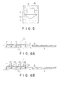
- Fig. 5 is a view similar to that of Fig. 3 showing another example of the float 7.
- the float 7 shown in Fig. 5 has a circular flanged portion 7a at the lower conical portion thereof in comparison with that of Fig. 3.
- the example of the float of Fig. 5 differs in this structure from that of Fig. 3.
- the flanged portion 7a is designed so as to have an outer diameter slightly smaller than an inner diameter of the vertical tube 5 to prevent the center of the float 7 from being shifted from the center of the vertical tube 5, which may be caused by the vibration of the fluid surface or the surface tension between the float 7 and the fluid 9 in the vertical tube 5.
- a plurality of openings may be directly formed to the communicating tube at portions corresponding to the measuring areas of the displacement sensors in place of the location of the vertical tubes.
- the floats will be disposed at portions of the openings in the floating manner.
- the floor level height varies so as to provide a curved surface and the large jig tool 1 is also deformed by its self-gravity.
- the communicating tube 4 disposed on the floor level FL is also deformed in accordance with the subsiding of the ground, but the surface level heights of the fluid at the opening portion of the respective vertical tubes 5 formed with the communicating tube 4 can be always maintained to the level surfaces.
- the positions of the displacement sensors 3 mounted to the respective leg members 1a of the large jig tool 1 vary in accordance with the subsiding of the ground, so that the respective displacement sensors 3 output signals representing the measured distances D1 - D5 which are different from the reference distance memorized in the state of Fig. 6A.
- the vertical displacements of the respective leg members 1a can be calculated by comparing the measured distances D1 - D5 with the reference distances of the respective displacement sensors 3 and operating the differences between the measured distances and the reference distances, respectively.
- the difference between the maximum displacement and the minimum displacement within the measured distances may be measured as a threshold value, and for example, in case of the threshold value exceeding 250 ⁇ m, an alarm will be generated through an alarm noise generating means or alarm display means to inform an operator of an abnormal condition.
- the outputs from the respective displacement sensors 3 are inputted into the data processing unit 21, the outputs are inputted every predetermined constant cycle or period as sampling values, and accordingly, in order to avoid the affect of the surface vibration of the fluid in the communicating tube, it is desired to calculate the moving average of 20, for example, numbers of sampling values. Further, it will be possible to forecast the tendency of the ground subsiding by statistically analyzing the change with age and the distribution of the measured data.
- the leg members 1a are thermally expanded through the temperature change in the surrounding environment
- the measurement can be realized with high precision according to the present invention by locating temperature sensors in the vicinities of the large jig tool 1, calculating the thermally expanded amount in accordance with a thermal expansion coefficient of the substance of the large jig tool 1 and then correcting the outputs from the respective displacement sensors 3.
- the screw jack means of Fig. 2 are operated to adjust all the vertical displacements to a constant value, for example, zero value.
- a constant value for example, zero value.
- the light sensor is utilized as the displacement sensor, but any other means for measuring a distance from the fluid surface or float may be utilized with no problem, and for example, a displacement sensor utilizing a capacitance type code or change of a magnetic field may be utilized.
- the change or deformation of a large jig tool with reference to a surface level can be monitored in a real time with high precision, so that the high performance of the large jig tool can be always maintained. Furthermore, tendency of ground subsiding can be clearly grasped by processing the measured data of the vertical displacement of leg members of the large jig tool, thus also improving the performance of the large jig tool.
Landscapes
- Physics & Mathematics (AREA)
- Engineering & Computer Science (AREA)
- General Physics & Mathematics (AREA)
- Radar, Positioning & Navigation (AREA)
- Remote Sensing (AREA)
- Testing Or Calibration Of Command Recording Devices (AREA)
- Level Indicators Using A Float (AREA)
Claims (6)
- Oberflächenniveau-Überwachungssystem für eine Gerüstvorrichtung (1), die mittels einer Mehrzahl von Tragelementen (la) auf einer Basis angeordnet ist, wobei eine Verformung der Gerüstvorrichtung (1) aufgrund eines unterschiedlichen Absinkens durch Veränderung im Verlauf der Zeit überwacht wird, mit:dadurch gekennzeichnet,einer Mehrzahl von Verlagerungssensoreinrichtungen (3), deren jede einen Meßbereich aufweist;ein Verbindungsrohr (4), in dem ein Fluid (9) eingefüllt ist, wobei das Verbindungsrohr (4) an den Meßbereichen der jeweiligen Verlagerungssensoreinrichtung (2) entsprechenden Bereichen mit einer Mehrzahl von Öffnungen (5a) versehen ist;einem Schwimmkörper (7), der in dem Fluid (9) in dem Verbindungsrohr (4) derart schwimmend angeordnet ist, daß er in einem vertikalen Rohr (5) nach Maßgabe einer Höhe einer Oberfläche des Fluids (9) vertikal beweglich ist und der einen unteren konischen Bereich aufweist; undmit einer Signalverarbeitungseinheit (21), die betriebsmäßig mit den Verlagerungssensoreinrichtungen (3) verbunden ist, um von diesen übertragene Signale zu verarbeiten und ein Oberflächenniveau der Gerüstvorrichtung (1) zu überwachen;daß jeweils eine von mehreren Verlagerungssensoreinrichtungen (3) an einem von mehreren Tragelementen (1a) der Gerüstvorrichtung (1) angebracht ist;daß das Verbindungsrohr (4) auf der Basis angeordnet ist; unddaß die in dem Verbindungsrohr (4) ausgebildeten Öffnungen (5a) jeweils eine kreisförmige Formgebung aufweisen und der Schwimmkörper (7) eine kreisförmige Säulenform besitzt und mit einem Flanschbereich (7a) versehen ist, der einen geringfügig kleineren Durchmesser als ein Innendurchmesser der Öffnung (5a) aufweist, so daß eine Verlagerung des Zentrums des Schwimmkörpers (7) von dem Zentrum des vertikalen Rohrs (5) verhindert ist, die durch die Vibration der Fluidoberfläche oder die Oberflächenspannung zwischen dem Schwimmkörper (7) und dem Fluid (9) in dem vertikalen Rohr (5) hevorgerufen werden kann.
- Oberflächenniveau-Überwachungssystem nach Anspruch 1,
wobei es sich bei den Verlagerungssensoreinrichtungen (3) um Lichtsensoren handelt und wobei der Schwimmkörper (7) mit einem lichtreflektierenden Element (8) versehen ist, das an einer oberen Oberfläche desselben angebracht ist. - Oberflächenniveau-Überwachungssystem nach Anspruch 1 oder 2,
wobei das Verbindungsrohr (4) mit einer Mehrzahl von vertikalen Rohren (5) versehen ist, die Endöffnungen (5a) aufweisen und in den Meßbereichen der jeweiligen Verlagerungssensoreinrichtungen (3) entsprechenden Bereichen positioniert sind. - Oberflächenniveau-Überwachungssystem nach Anspruch 3,
wobei eine Mehrzahl von Schwimmkörpern (7) in dem Fluid in den vertikalen Rohren (5) jeweils derart schwimmend angeordnet ist, daß sie nach Maßgabe einer Oberflächenhöhe des Fluids vertikal beweglich sind. - Oberflächenniveau-Überwachungssystem nach einem der Ansprüche 1 bis 4,
wobei die Tragelemente (1a) Hebereinrichtungen (10, 11, 12) zum Konstanthalten von allen Oberflächenniveaus der Tragelemente (1a) aufweisen. - Oberflächenniveau-Überwachungssystem nach einem der Ansprüche 1 bis 5,
wobei ferner ein Temperatursensor in Zuordnung zu der Gerüstvorrichtung (1) vorgesehen ist, um einen Wärmeausdehnungskoeffizienten der Gerüstvorrichtung (1) nach Maßgabe eines die Gerüstvorrichtung (1) bildenden Materials zu berechnen und um ein Ausgangssignal von dem Verlagerungssensor (3) nach Maßgabe des Wärmeausdehnungskoeffizienten zu korrigieren.
Applications Claiming Priority (2)
| Application Number | Priority Date | Filing Date | Title |
|---|---|---|---|
| JP158920/93 | 1993-06-29 | ||
| JP5158920A JP2746822B2 (ja) | 1993-06-29 | 1993-06-29 | 大型治工具の水準面監視装置 |
Publications (2)
| Publication Number | Publication Date |
|---|---|
| EP0632251A1 EP0632251A1 (de) | 1995-01-04 |
| EP0632251B1 true EP0632251B1 (de) | 1998-11-11 |
Family
ID=15682234
Family Applications (1)
| Application Number | Title | Priority Date | Filing Date |
|---|---|---|---|
| EP19940110113 Expired - Lifetime EP0632251B1 (de) | 1993-06-29 | 1994-06-29 | Verformungsüberwachungssystem für Ausrichtvorrichtung |
Country Status (3)
| Country | Link |
|---|---|
| EP (1) | EP0632251B1 (de) |
| JP (1) | JP2746822B2 (de) |
| DE (1) | DE69414475T2 (de) |
Cited By (3)
| Publication number | Priority date | Publication date | Assignee | Title |
|---|---|---|---|---|
| CN102384742A (zh) * | 2011-10-15 | 2012-03-21 | 赵志强 | 浮筒式水平倾角测量装置 |
| CN102519426A (zh) * | 2011-11-28 | 2012-06-27 | 长沙理工大学 | 一种浮标位移计式路基差异沉降测试仪 |
| WO2012145884A1 (zh) * | 2011-04-25 | 2012-11-01 | 中国人民解放军国防科学技术大学 | 一种工程建筑沉降的监测方法与监测系统 |
Families Citing this family (7)
| Publication number | Priority date | Publication date | Assignee | Title |
|---|---|---|---|---|
| US5937529A (en) * | 1997-04-14 | 1999-08-17 | Level-Tech International, Llc | Apparatus for measuring vertical displacement |
| FR2790548B1 (fr) * | 1999-03-02 | 2001-04-13 | Isp System | Capteur magnetostrictif et dispositif destine a la mise au theorique et a la surveillance geometrique de tables faisant application |
| DE102006011297A1 (de) * | 2006-03-11 | 2007-09-13 | Man Roland Druckmaschinen Ag | Druckmaschinenmessanordnung sowie Messeinheit für eine Messanordnung |
| EP2734807B1 (de) * | 2011-07-19 | 2015-05-06 | Carl Zeiss Industrielle Messtechnik GmbH | Koordinatenmessgerät mit einer vorrichtung aus kommunizierenden röhren |
| JP6088861B2 (ja) * | 2013-03-13 | 2017-03-01 | 株式会社大林組 | 開水路式変位計 |
| ES2747383T3 (es) * | 2014-02-27 | 2020-03-10 | Fidia Spa | Método y sistema para verificar la precisión de posicionamiento de una máquina CNC |
| CN106092046B (zh) * | 2016-08-15 | 2019-01-04 | 中国电建集团贵阳勘测设计研究院有限公司 | 一种单连通封闭压力式沉降测量系统及其测量方法 |
Family Cites Families (10)
| Publication number | Priority date | Publication date | Assignee | Title |
|---|---|---|---|---|
| US3949484A (en) * | 1974-05-22 | 1976-04-13 | The English Electric Company Limited | Vertical movement detection systems |
| JPS55152405A (en) * | 1979-05-18 | 1980-11-27 | Hitachi Ltd | Displacement amount monitoring system for stand |
| US4511247A (en) * | 1982-08-31 | 1985-04-16 | Mcgovern Paul A | Surveying technique with correction of optical errors caused by atmospheric turbulence |
| JPS60146119A (ja) * | 1984-01-10 | 1985-08-01 | Sumitomo Electric Ind Ltd | 液面レベル検出器 |
| JPS60179607A (ja) * | 1984-02-27 | 1985-09-13 | Osaka Doshitsu Shikenjo | 連通管式沈下計 |
| JPS61137214U (de) * | 1985-02-18 | 1986-08-26 | ||
| JPS63120213A (ja) * | 1986-11-07 | 1988-05-24 | Ishikawajima Kensa Keisoku Kk | 大型構造物等のレベル計測方法 |
| JPH01123115A (ja) * | 1987-11-07 | 1989-05-16 | Power Reactor & Nuclear Fuel Dev Corp | 浮子式レーザレベル計 |
| JPH0519921U (ja) * | 1991-03-06 | 1993-03-12 | 昭和電線電纜株式会社 | 液量指示装置 |
| JP3125848U (ja) * | 2006-07-21 | 2006-10-05 | 三喜男 小野 | スプレー補助具 |
-
1993
- 1993-06-29 JP JP5158920A patent/JP2746822B2/ja not_active Expired - Fee Related
-
1994
- 1994-06-29 DE DE1994614475 patent/DE69414475T2/de not_active Expired - Fee Related
- 1994-06-29 EP EP19940110113 patent/EP0632251B1/de not_active Expired - Lifetime
Cited By (4)
| Publication number | Priority date | Publication date | Assignee | Title |
|---|---|---|---|---|
| WO2012145884A1 (zh) * | 2011-04-25 | 2012-11-01 | 中国人民解放军国防科学技术大学 | 一种工程建筑沉降的监测方法与监测系统 |
| CN102384742A (zh) * | 2011-10-15 | 2012-03-21 | 赵志强 | 浮筒式水平倾角测量装置 |
| CN102384742B (zh) * | 2011-10-15 | 2013-04-17 | 赵志强 | 浮筒式水平倾角测量装置 |
| CN102519426A (zh) * | 2011-11-28 | 2012-06-27 | 长沙理工大学 | 一种浮标位移计式路基差异沉降测试仪 |
Also Published As
| Publication number | Publication date |
|---|---|
| DE69414475D1 (de) | 1998-12-17 |
| JPH0712624A (ja) | 1995-01-17 |
| JP2746822B2 (ja) | 1998-05-06 |
| DE69414475T2 (de) | 1999-09-09 |
| EP0632251A1 (de) | 1995-01-04 |
Similar Documents
| Publication | Publication Date | Title |
|---|---|---|
| US8537372B2 (en) | Coordinate measuring machine (CMM) and method of compensating errors in a CMM | |
| EP0632251B1 (de) | Verformungsüberwachungssystem für Ausrichtvorrichtung | |
| US4782598A (en) | Active error compensation in a coordinate measuring machine | |
| US6442857B1 (en) | Portable surface inspector | |
| US4773760A (en) | Procedure and means for measuring the thickness of a film-like or sheet-like web | |
| CN108351203B (zh) | 提供精确坐标测量的方法、独立基准模块和坐标测量机 | |
| JPH04350513A (ja) | レーザー光線水準計測器 | |
| US4730927A (en) | Method and apparatus for measuring positions on the surface of a flat object | |
| US6188078B1 (en) | Optical metrology device for precision angular measurement of a pointing mirror | |
| CN113432625A (zh) | 一种静力水准仪的定标系统及定标方法 | |
| US5847820A (en) | Laser apparatus for sensing rotational orientation and levelness | |
| JP5290038B2 (ja) | 測定装置及び測定方法 | |
| CN110361067B (zh) | 一种液面高度测量装置 | |
| US5587900A (en) | Self leveling independently programmable system | |
| Wick et al. | An accurate measurement of g using falling balls | |
| GB2263338A (en) | Metrological apparatus. | |
| JPH05223526A (ja) | 板厚測定装置 | |
| JP4444531B2 (ja) | 簡易検測車およびその較正方法 | |
| JPH11218941A (ja) | ステージ装置およびこれを用いた露光装置 | |
| CN110658686B (zh) | 清除装置、光刻设备和光刻方法 | |
| JPH0694412A (ja) | 干渉計装置 | |
| GB2185333A (en) | Checking vertical alignment | |
| JPH0843041A (ja) | 三次元形状測定方法及び装置 | |
| CN118347375A (zh) | 一种用于高精度水平度测量的游标高度尺及其测量方法 | |
| JP2007178137A (ja) | 表面形状変位量の測定装置及び測定方法 |
Legal Events
| Date | Code | Title | Description |
|---|---|---|---|
| PUAI | Public reference made under article 153(3) epc to a published international application that has entered the european phase |
Free format text: ORIGINAL CODE: 0009012 |
|
| 17P | Request for examination filed |
Effective date: 19940629 |
|
| AK | Designated contracting states |
Kind code of ref document: A1 Designated state(s): DE FR GB |
|
| 17Q | First examination report despatched |
Effective date: 19961206 |
|
| GRAG | Despatch of communication of intention to grant |
Free format text: ORIGINAL CODE: EPIDOS AGRA |
|
| GRAG | Despatch of communication of intention to grant |
Free format text: ORIGINAL CODE: EPIDOS AGRA |
|
| GRAH | Despatch of communication of intention to grant a patent |
Free format text: ORIGINAL CODE: EPIDOS IGRA |
|
| GRAH | Despatch of communication of intention to grant a patent |
Free format text: ORIGINAL CODE: EPIDOS IGRA |
|
| GRAA | (expected) grant |
Free format text: ORIGINAL CODE: 0009210 |
|
| AK | Designated contracting states |
Kind code of ref document: B1 Designated state(s): DE FR GB |
|
| REF | Corresponds to: |
Ref document number: 69414475 Country of ref document: DE Date of ref document: 19981217 |
|
| ET | Fr: translation filed | ||
| PLBE | No opposition filed within time limit |
Free format text: ORIGINAL CODE: 0009261 |
|
| STAA | Information on the status of an ep patent application or granted ep patent |
Free format text: STATUS: NO OPPOSITION FILED WITHIN TIME LIMIT |
|
| 26N | No opposition filed | ||
| REG | Reference to a national code |
Ref country code: GB Ref legal event code: IF02 |
|
| PGFP | Annual fee paid to national office [announced via postgrant information from national office to epo] |
Ref country code: FR Payment date: 20040608 Year of fee payment: 11 |
|
| PGFP | Annual fee paid to national office [announced via postgrant information from national office to epo] |
Ref country code: GB Payment date: 20040623 Year of fee payment: 11 |
|
| PGFP | Annual fee paid to national office [announced via postgrant information from national office to epo] |
Ref country code: DE Payment date: 20040708 Year of fee payment: 11 |
|
| PG25 | Lapsed in a contracting state [announced via postgrant information from national office to epo] |
Ref country code: GB Free format text: LAPSE BECAUSE OF NON-PAYMENT OF DUE FEES Effective date: 20050629 |
|
| PG25 | Lapsed in a contracting state [announced via postgrant information from national office to epo] |
Ref country code: DE Free format text: LAPSE BECAUSE OF NON-PAYMENT OF DUE FEES Effective date: 20060103 |
|
| PG25 | Lapsed in a contracting state [announced via postgrant information from national office to epo] |
Ref country code: FR Free format text: LAPSE BECAUSE OF NON-PAYMENT OF DUE FEES Effective date: 20060228 |
|
| GBPC | Gb: european patent ceased through non-payment of renewal fee |
Effective date: 20050629 |
|
| REG | Reference to a national code |
Ref country code: FR Ref legal event code: ST Effective date: 20060228 |