EP0660259A2 - Steuerknüppelartige Bedienungskebeleinrichtung - Google Patents
Steuerknüppelartige Bedienungskebeleinrichtung Download PDFInfo
- Publication number
- EP0660259A2 EP0660259A2 EP94309151A EP94309151A EP0660259A2 EP 0660259 A2 EP0660259 A2 EP 0660259A2 EP 94309151 A EP94309151 A EP 94309151A EP 94309151 A EP94309151 A EP 94309151A EP 0660259 A2 EP0660259 A2 EP 0660259A2
- Authority
- EP
- European Patent Office
- Prior art keywords
- control section
- joy stick
- stick type
- output
- sub
- Prior art date
- Legal status (The legal status is an assumption and is not a legal conclusion. Google has not performed a legal analysis and makes no representation as to the accuracy of the status listed.)
- Withdrawn
Links
Images



Classifications
-
- G—PHYSICS
- G06—COMPUTING OR CALCULATING; COUNTING
- G06F—ELECTRIC DIGITAL DATA PROCESSING
- G06F11/00—Error detection; Error correction; Monitoring
- G06F11/07—Responding to the occurrence of a fault, e.g. fault tolerance
- G06F11/16—Error detection or correction of the data by redundancy in hardware
- G06F11/20—Error detection or correction of the data by redundancy in hardware using active fault-masking, e.g. by switching out faulty elements or by switching in spare elements
-
- Y—GENERAL TAGGING OF NEW TECHNOLOGICAL DEVELOPMENTS; GENERAL TAGGING OF CROSS-SECTIONAL TECHNOLOGIES SPANNING OVER SEVERAL SECTIONS OF THE IPC; TECHNICAL SUBJECTS COVERED BY FORMER USPC CROSS-REFERENCE ART COLLECTIONS [XRACs] AND DIGESTS
- Y10—TECHNICAL SUBJECTS COVERED BY FORMER USPC
- Y10T—TECHNICAL SUBJECTS COVERED BY FORMER US CLASSIFICATION
- Y10T74/00—Machine element or mechanism
- Y10T74/20—Control lever and linkage systems
- Y10T74/20012—Multiple controlled elements
- Y10T74/20201—Control moves in two planes
Definitions
- the present invention relates to a joy stick type operating lever device used in construction equipment such as hydraulic shovels, bulldozers, or cranes, or in ships.
- an operating lever which can be operated two dimensionally, for example, forward and backward, right and left, or vertically and horizontally, in an X - Y plane.
- various operation controls are carried out based on detection signal data from each of the lever operation angle detecting means.
- detection signal of each of the lever operation angle detecting means is input to the main control section side.
- detection signals have been input to the main control section using a total of at least four lines, two lines for outputting signals from each of the lever operation angle detection means, and a supply line and a ground line. This has meant that an equal number of connectors as lines had to be provided at the main control section side.
- the present invention aims at providing a joy stick type operating lever device provided with at least lever operation angle detecting means for detecting operation angle in the X or Y direction of a joy stick type operation lever, the joy stick type operating lever device being provided with a sub-control section for accepting signal data, which have been output from these means, and for arranging each of the input signal data into serial data, which is output to the main control section side.
- the present invention is so constructed to allow signal data from the joy stick type operating levers to be sent to the main control section side using a minimum number of wires.
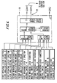
- each reference numeral 1 denotes an operation box, one being provided on the left hand side and the other on the right hand side of the operator's seat.
- a joy stick type operating lever la which can be operated two dimensionally in an X - Y plane.
- a lever angle detecting means 2 and 3 for detecting the operation angle in the X or Y direction of each lever 1a. The operation angle of each lever 1a, operated in the X or Y direction, is detected, and, then, the corresponding detection signal data is generated.
- each of the operating boxes 1 there are provided respectively switches such as neutral switches 4 and 5 for allowing data output when the operating levers 1 have been operated in the X or Y direction to a neutral position; and one or more change-over switches 6 for arbitrarily selecting a desired function.
- Data signals can be generated based on the operation of each switch 4, 5, or 6 as they have been generated conventionally.
- each of the operating boxes 1 there can be provided in addition to the aforementioned operating levers 1a, and other types of switches, setting units which, for example, set an operating range. Such setting units will not be described below because they can be used as the aforementioned lever angle detecting means or switches.
- Reference numeral 7 each denote a sub-control section which accepts as an input signal data which have each been generated from the lever angle detecting means 2 and 3, and the switches 4, 5, and 6, respectively.
- Each sub-control section 7, which is provided in its respective operating box 1, is formed by various circuits: a central control circuit (CPU) 8, an an A to D conversion circuit (analog-to-digital converter) 9, a digital input circuit 10, a memory circuit 11, and a serial signal output circuit 12.
- the lever angle detecting means 2 and 3 are connected to the AD conversion circuit 9 such as to allow the detection signal data (in analog form) to be input to the AD conversion circuit 9.
- the detection signal data regarding the operation angle of each operating lever 1a in the X or Y direction is set such that it is converted into digital signals by the AD conversion circuit 9 and stored in the memory circuit 11.
- Switches such as the neutral switches 4 and 5 as well as the change-over switch or switches 6 are connected such that their corresponding signal data are each input to the digital input circuit 10.
- the input signal data are set such that they are stored in the memory circuit 11.
- the central control circuit 8 reads in each signal data, which has been stored in the memory circuit 11. Then, these signal data, which have been read in, are rearranged into a proper order into one serial data stream.
- the serial data is set such that it is output via the serial signal output circuit 12.
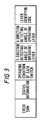
- the different signal data, given below, comprising the serial data are output in the order shown in Fig.
- lever identification code for identifying the operating lever la (the right one or the left one); (2) detection angle corresponding to the lever operation angle in the X direction; (3) detection angle corresponding to the lever operation angle in the Y direction; (4) operating condition of each of the switches 4, 5, and 6; (5) status information (diagnosis information such as abnormal memory, faulty data, etc.); and finally (6) check sum data which is the sum total of all of the preceding data.
- the serial signal data which have been arranged in this order, are set so that they are output on serial signal output lines 13, which are formed by COM 1 and COM 2 respectively, via the serial signal output circuit 12.
- each of the left and right operating levers 1a is provided with a sub-control section 7.
- the serial output lines 13 from the sub-control sections 7 are brought together to form one signal line, which is connected at a main control section side.
- signal data such as lever operation angle detection signal
- the serial data of each of the operating levers 1a may collide with each other at the point where the output lines meet.
- the embodiment provides in each of the sub-control sections 7 a communication scheduling function which allows detection of the condition of use of the aforementioned signal line and allows output of the serial data when the signal line is not used.
- the angle detection data of each of the joy stick type operating levers la as well as the signal data from each of the switches 4, 5, and 6, are temporarily input to the respective sub-control sections 7 and then stored in the memory circuit 11. Then, these signal data are arranged to form serial data, which is transmitted from the serial signal output circuit 12 to the main control section side.
- This allows the detection signal from the lever angle detecting means 2 and 3 and the signal data from each of the switches 4, 5, and 6 to be output from the same serial signal output line 13. Consequently, it is not necessary to use separate wires for each signal data for connection to the main control section as has been used conventionally. This reduces the number of wire connections to the main control section, which permits connections to be carried out more easily and at a reduced cost.
- serial signal output lines from the sub-control sections 7 are brought together to form one signal line, which is connected to the main control section. This reduces the number of wires connected to the main control section, which significantly reduces the occurrence of faulty connections and makes the operating lever device highly reliable.
- any abnormality can be detected at the main control section side to which is input signal data from the serial signal output circuit 12 by merely referring to the status information. Therefore, the load required for self diagnosis can be reduced.
- Various kinds of self-diagnosis can be freely performed, which include memory checking, monitoring the relationship between the lever operation input and the neutral switch ON/OFF state, and supply voltage. This results in a further higher reliability.
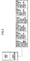
- a plurality of operating levers 1a can be connected to a single sub-control section.
- signal data from each of the operating levers can be input to the main control section by simply incorporating a plurality of signal data into a serial data, as shown in Fig. 5, without increasing the number of sub-control sections or signal output lines. This significantly reduces the number of component parts and the number of wires, which leads to considerably reduced costs.
- the present invention allows the number of wire connections to be reduced, so that wire connecting is simplified and costs are reduced.
- This is made possible by the construction of the invention in which signal data resulting from the operation of the joy stick type operating levers are each temporarily input in the sub-control section. Then, the signal data are rearranged into serial data and output to the main control section. The same signal line can be used between the sub-control section and the main control section, so that a wire is not required for every signal data as in conventional operating lever devices.
Landscapes
- Engineering & Computer Science (AREA)
- Theoretical Computer Science (AREA)
- Quality & Reliability (AREA)
- Physics & Mathematics (AREA)
- General Engineering & Computer Science (AREA)
- General Physics & Mathematics (AREA)
- Position Input By Displaying (AREA)
- Mechanical Control Devices (AREA)
- Operation Control Of Excavators (AREA)
- Control Of Position Or Direction (AREA)
Applications Claiming Priority (2)
| Application Number | Priority Date | Filing Date | Title |
|---|---|---|---|
| JP5340752A JPH07160413A (ja) | 1993-12-09 | 1993-12-09 | ジョイスティック型操作レバー装置 |
| JP340752/93 | 1993-12-09 |
Publications (2)
| Publication Number | Publication Date |
|---|---|
| EP0660259A2 true EP0660259A2 (de) | 1995-06-28 |
| EP0660259A3 EP0660259A3 (de) | 1996-11-27 |
Family
ID=18339970
Family Applications (1)
| Application Number | Title | Priority Date | Filing Date |
|---|---|---|---|
| EP94309151A Withdrawn EP0660259A3 (de) | 1993-12-09 | 1994-12-08 | Steuerknüppelartige Bedienungskebeleinrichtung. |
Country Status (4)
| Country | Link |
|---|---|
| US (1) | US5550539A (de) |
| EP (1) | EP0660259A3 (de) |
| JP (1) | JPH07160413A (de) |
| CA (1) | CA2137630C (de) |
Cited By (1)
| Publication number | Priority date | Publication date | Assignee | Title |
|---|---|---|---|---|
| FR2768286A1 (fr) * | 1997-09-05 | 1999-03-12 | Philippe Jean Bordelais | Report de commande pour camera installee sur un systeme portatif |
Families Citing this family (8)
| Publication number | Priority date | Publication date | Assignee | Title |
|---|---|---|---|---|
| USH1831H (en) * | 1998-12-18 | 2000-02-01 | Caterpillar Inc. | Ergonomic motor grader vehicle control apparatus |
| JP4558128B2 (ja) * | 2000-02-28 | 2010-10-06 | 日本車輌製造株式会社 | 建設機械のウインチ |
| DE202006002969U1 (de) * | 2005-11-08 | 2006-05-11 | Agco Gmbh | Steuereinrichtung für Nutzfahrzeuge |
| EP2214945B1 (de) * | 2007-12-03 | 2011-09-07 | Bozzio AG | Behindertengerechtes fahrzeug |
| JP5170683B2 (ja) * | 2008-11-04 | 2013-03-27 | 株式会社デンソー | 車載用遠隔操作装置 |
| US8820463B2 (en) * | 2011-09-27 | 2014-09-02 | Shane Phillips | Safety control systems and methods for heavy equipment |
| CN109690309B (zh) * | 2016-09-08 | 2022-10-25 | 株式会社岛津制作所 | 气相色谱仪 |
| CN112130521B (zh) * | 2020-09-22 | 2021-04-20 | 郑州嘉晨电器有限公司 | 一种用于工程机械安全操控的控制装置 |
Family Cites Families (7)
| Publication number | Priority date | Publication date | Assignee | Title |
|---|---|---|---|---|
| US4161726A (en) * | 1977-04-06 | 1979-07-17 | Texas Instruments Incorporated | Digital joystick control |
| GB2196449B (en) * | 1986-10-14 | 1988-09-21 | Creative Devices Res Ltd | Electrical switch assembly |
| US4924216A (en) * | 1988-02-12 | 1990-05-08 | Acemore International Ltd. | Joystick controller apparatus |
| FR2648580B1 (fr) * | 1989-06-16 | 1991-09-20 | Rexroth Sigma | Procede pour etalonner un dispositif de telecommande electrique du type manipulateur ou analogue, et dispositif agence pour mettre en oeuvre ce procede |
| US5230059A (en) * | 1990-07-16 | 1993-07-20 | Kraft Systems, Inc. | Software - configurable adaptive computer interface |
| US5134395A (en) * | 1990-08-10 | 1992-07-28 | Ambrosia Microcomputer Products, Inc. | Joystick/switch interface to computer serial port |
| JP2960787B2 (ja) * | 1991-01-31 | 1999-10-12 | オークマ株式会社 | 2次元変位検出器 |
-
1993
- 1993-12-09 JP JP5340752A patent/JPH07160413A/ja active Pending
-
1994
- 1994-12-06 US US08/354,082 patent/US5550539A/en not_active Expired - Lifetime
- 1994-12-08 EP EP94309151A patent/EP0660259A3/de not_active Withdrawn
- 1994-12-08 CA CA002137630A patent/CA2137630C/en not_active Expired - Fee Related
Cited By (1)
| Publication number | Priority date | Publication date | Assignee | Title |
|---|---|---|---|---|
| FR2768286A1 (fr) * | 1997-09-05 | 1999-03-12 | Philippe Jean Bordelais | Report de commande pour camera installee sur un systeme portatif |
Also Published As
| Publication number | Publication date |
|---|---|
| US5550539A (en) | 1996-08-27 |
| CA2137630C (en) | 1999-06-29 |
| CA2137630A1 (en) | 1995-06-10 |
| EP0660259A3 (de) | 1996-11-27 |
| JPH07160413A (ja) | 1995-06-23 |
Similar Documents
| Publication | Publication Date | Title |
|---|---|---|
| EP0632193B1 (de) | Fehlerdiagnosevorrichtung und -verfahren für Fahrzeugsteuerungssystem | |
| US6275881B1 (en) | Device for inherently safe signal matching | |
| US5550539A (en) | Joy stick type operating lever device | |
| US20240160589A1 (en) | I/o unit | |
| KR900004372B1 (ko) | 자동차용 전자장치의 고장진단 시스템 | |
| US20070066147A1 (en) | Modular control system with terminal and function modules | |
| US6411866B1 (en) | Digital transmission and control system for vehicles | |
| US4910678A (en) | Failure memory device | |
| JPH0612483B2 (ja) | プロセスコントロ−ルシステム | |
| US4853831A (en) | Bus connection structure for interruption control system | |
| JP2564740Y2 (ja) | 端末アダプタ | |
| US6871103B2 (en) | Car wash controller | |
| JPH0738961Y2 (ja) | 動作モード設定回路 | |
| JPH01211099A (ja) | ガス検知警報装置 | |
| KR910002963Y1 (ko) | 센서신호의 점검용 어댑터 모듈(adapter module) | |
| JP2888199B2 (ja) | リモートシグナルコンデショナ | |
| JPS59133796A (ja) | 自動車の集約配線システムにおける異常検出装置 | |
| JPS61112494A (ja) | 遠方監視制御装置 | |
| JPH0720903A (ja) | 多重化制御装置 | |
| JPH0641896B2 (ja) | 自動車に使用される信号路選択装置 | |
| JPH06168060A (ja) | 識別コードを2進信号に変換する方法と装置 | |
| JP2002008748A (ja) | 信号変換機能付端子台 | |
| CN117043691A (zh) | I/o单元以及通信系统 | |
| JPS6026407A (ja) | 試験端子付ジヤンクシヨンボツクス | |
| JPS59128180A (ja) | エレベ−タ制御装置 |
Legal Events
| Date | Code | Title | Description |
|---|---|---|---|
| PUAI | Public reference made under article 153(3) epc to a published international application that has entered the european phase |
Free format text: ORIGINAL CODE: 0009012 |
|
| 17P | Request for examination filed |
Effective date: 19941220 |
|
| AK | Designated contracting states |
Kind code of ref document: A2 Designated state(s): BE DE FR GB |
|
| PUAL | Search report despatched |
Free format text: ORIGINAL CODE: 0009013 |
|
| AK | Designated contracting states |
Kind code of ref document: A3 Designated state(s): BE DE FR GB |
|
| 17Q | First examination report despatched |
Effective date: 19990830 |
|
| STAA | Information on the status of an ep patent application or granted ep patent |
Free format text: STATUS: THE APPLICATION IS DEEMED TO BE WITHDRAWN |
|
| 18D | Application deemed to be withdrawn |
Effective date: 20000111 |