EP0703494B1 - Infrarot absorbierenden Farbstoff photographisches Silberhalogenidmaterial - Google Patents
Infrarot absorbierenden Farbstoff photographisches Silberhalogenidmaterial Download PDFInfo
- Publication number
- EP0703494B1 EP0703494B1 EP95114966A EP95114966A EP0703494B1 EP 0703494 B1 EP0703494 B1 EP 0703494B1 EP 95114966 A EP95114966 A EP 95114966A EP 95114966 A EP95114966 A EP 95114966A EP 0703494 B1 EP0703494 B1 EP 0703494B1
- Authority
- EP
- European Patent Office
- Prior art keywords
- group
- photographic material
- colorant
- silver halide
- image forming
- Prior art date
- Legal status (The legal status is an assumption and is not a legal conclusion. Google has not performed a legal analysis and makes no representation as to the accuracy of the status listed.)
- Expired - Lifetime
Links
- 239000000463 material Substances 0.000 title claims description 78
- 239000003086 colorant Substances 0.000 title claims description 65
- -1 Silver halide Chemical class 0.000 title claims description 60
- 229910052709 silver Inorganic materials 0.000 title claims description 54
- 239000004332 silver Substances 0.000 title claims description 54
- 239000010410 layer Substances 0.000 claims description 57
- 125000000217 alkyl group Chemical group 0.000 claims description 41
- 238000010521 absorption reaction Methods 0.000 claims description 40
- 238000000034 method Methods 0.000 claims description 38
- 239000000839 emulsion Substances 0.000 claims description 37
- 239000002245 particle Substances 0.000 claims description 32
- 125000001424 substituent group Chemical group 0.000 claims description 30
- 230000008569 process Effects 0.000 claims description 25
- 239000007787 solid Substances 0.000 claims description 25
- 230000007246 mechanism Effects 0.000 claims description 23
- 125000003118 aryl group Chemical group 0.000 claims description 18
- 125000001997 phenyl group Chemical group [H]C1=C([H])C([H])=C(*)C([H])=C1[H] 0.000 claims description 16
- 125000000623 heterocyclic group Chemical group 0.000 claims description 14
- ANRHNWWPFJCPAZ-UHFFFAOYSA-M thionine Chemical group [Cl-].C1=CC(N)=CC2=[S+]C3=CC(N)=CC=C3N=C21 ANRHNWWPFJCPAZ-UHFFFAOYSA-M 0.000 claims description 14
- 229910052739 hydrogen Inorganic materials 0.000 claims description 11
- 239000001257 hydrogen Substances 0.000 claims description 11
- 125000004435 hydrogen atom Chemical group [H]* 0.000 claims description 11
- BQCADISMDOOEFD-UHFFFAOYSA-N Silver Chemical compound [Ag] BQCADISMDOOEFD-UHFFFAOYSA-N 0.000 claims description 10
- 125000003342 alkenyl group Chemical group 0.000 claims description 10
- 125000003710 aryl alkyl group Chemical group 0.000 claims description 10
- 125000005843 halogen group Chemical group 0.000 claims description 10
- 239000011241 protective layer Substances 0.000 claims description 10
- QJGQUHMNIGDVPM-UHFFFAOYSA-N nitrogen group Chemical group [N] QJGQUHMNIGDVPM-UHFFFAOYSA-N 0.000 claims description 9
- 125000000129 anionic group Chemical group 0.000 claims description 7
- 125000001434 methanylylidene group Chemical group [H]C#[*] 0.000 claims description 7
- 150000001450 anions Chemical group 0.000 claims description 6
- 125000002252 acyl group Chemical group 0.000 claims description 5
- 125000003545 alkoxy group Chemical group 0.000 claims description 5
- 125000004390 alkyl sulfonyl group Chemical group 0.000 claims description 5
- 125000004391 aryl sulfonyl group Chemical group 0.000 claims description 5
- 125000004104 aryloxy group Chemical group 0.000 claims description 5
- 150000001768 cations Chemical class 0.000 claims description 5
- 125000005647 linker group Chemical group 0.000 claims description 4
- 125000004414 alkyl thio group Chemical group 0.000 claims description 3
- 125000005110 aryl thio group Chemical group 0.000 claims description 3
- 230000006870 function Effects 0.000 claims description 3
- 239000000243 solution Substances 0.000 description 57
- 239000000975 dye Substances 0.000 description 49
- OKKJLVBELUTLKV-UHFFFAOYSA-N Methanol Chemical compound OC OKKJLVBELUTLKV-UHFFFAOYSA-N 0.000 description 33
- 150000001875 compounds Chemical class 0.000 description 31
- 125000004432 carbon atom Chemical group C* 0.000 description 25
- 230000015572 biosynthetic process Effects 0.000 description 23
- 239000000203 mixture Substances 0.000 description 18
- 238000003786 synthesis reaction Methods 0.000 description 18
- 125000002496 methyl group Chemical group [H]C([H])([H])* 0.000 description 17
- XLYOFNOQVPJJNP-UHFFFAOYSA-N water Substances O XLYOFNOQVPJJNP-UHFFFAOYSA-N 0.000 description 17
- 108010010803 Gelatin Proteins 0.000 description 16
- 239000008273 gelatin Substances 0.000 description 16
- 229920000159 gelatin Polymers 0.000 description 16
- 235000019322 gelatine Nutrition 0.000 description 16
- 235000011852 gelatine desserts Nutrition 0.000 description 16
- ZMANZCXQSJIPKH-UHFFFAOYSA-N Triethylamine Chemical compound CCN(CC)CC ZMANZCXQSJIPKH-UHFFFAOYSA-N 0.000 description 15
- 125000003178 carboxy group Chemical group [H]OC(*)=O 0.000 description 14
- 239000000460 chlorine Substances 0.000 description 14
- 239000011248 coating agent Substances 0.000 description 14
- 238000000576 coating method Methods 0.000 description 14
- 230000035945 sensitivity Effects 0.000 description 13
- IAZDPXIOMUYVGZ-UHFFFAOYSA-N Dimethylsulphoxide Chemical compound CS(C)=O IAZDPXIOMUYVGZ-UHFFFAOYSA-N 0.000 description 11
- 239000007864 aqueous solution Substances 0.000 description 10
- IOLCXVTUBQKXJR-UHFFFAOYSA-M potassium bromide Chemical compound [K+].[Br-] IOLCXVTUBQKXJR-UHFFFAOYSA-M 0.000 description 10
- WFDIJRYMOXRFFG-UHFFFAOYSA-N Acetic anhydride Chemical compound CC(=O)OC(C)=O WFDIJRYMOXRFFG-UHFFFAOYSA-N 0.000 description 9
- 239000013078 crystal Substances 0.000 description 9
- 230000001681 protective effect Effects 0.000 description 9
- QTBSBXVTEAMEQO-UHFFFAOYSA-N Acetic acid Chemical compound CC(O)=O QTBSBXVTEAMEQO-UHFFFAOYSA-N 0.000 description 7
- 229910052794 bromium Inorganic materials 0.000 description 7
- 229910052801 chlorine Inorganic materials 0.000 description 7
- 239000006185 dispersion Substances 0.000 description 7
- 229910052731 fluorine Inorganic materials 0.000 description 7
- 150000003839 salts Chemical class 0.000 description 7
- 239000002904 solvent Substances 0.000 description 7
- 239000004094 surface-active agent Substances 0.000 description 7
- WCUXLLCKKVVCTQ-UHFFFAOYSA-M Potassium chloride Chemical compound [Cl-].[K+] WCUXLLCKKVVCTQ-UHFFFAOYSA-M 0.000 description 6
- HEMHJVSKTPXQMS-UHFFFAOYSA-M Sodium hydroxide Chemical compound [OH-].[Na+] HEMHJVSKTPXQMS-UHFFFAOYSA-M 0.000 description 6
- 125000004453 alkoxycarbonyl group Chemical group 0.000 description 6
- 125000000484 butyl group Chemical group [H]C([*])([H])C([H])([H])C([H])([H])C([H])([H])[H] 0.000 description 6
- 125000003754 ethoxycarbonyl group Chemical group C(=O)(OCC)* 0.000 description 6
- SQGYOTSLMSWVJD-UHFFFAOYSA-N silver(1+) nitrate Chemical compound [Ag+].[O-]N(=O)=O SQGYOTSLMSWVJD-UHFFFAOYSA-N 0.000 description 6
- LFQSCWFLJHTTHZ-UHFFFAOYSA-N Ethanol Chemical compound CCO LFQSCWFLJHTTHZ-UHFFFAOYSA-N 0.000 description 5
- 239000000084 colloidal system Substances 0.000 description 5
- 238000002360 preparation method Methods 0.000 description 5
- HEDRZPFGACZZDS-UHFFFAOYSA-N Chloroform Chemical compound ClC(Cl)Cl HEDRZPFGACZZDS-UHFFFAOYSA-N 0.000 description 4
- FAPWRFPIFSIZLT-UHFFFAOYSA-M Sodium chloride Chemical compound [Na+].[Cl-] FAPWRFPIFSIZLT-UHFFFAOYSA-M 0.000 description 4
- 235000010724 Wisteria floribunda Nutrition 0.000 description 4
- 239000002253 acid Substances 0.000 description 4
- 125000001495 ethyl group Chemical group [H]C([H])([H])C([H])([H])* 0.000 description 4
- 125000004051 hexyl group Chemical group [H]C([H])([H])C([H])([H])C([H])([H])C([H])([H])C([H])([H])C([H])([H])* 0.000 description 4
- RKJUIXBNRJVNHR-UHFFFAOYSA-N indolenine group Chemical group N1=CCC2=CC=CC=C12 RKJUIXBNRJVNHR-UHFFFAOYSA-N 0.000 description 4
- 125000000959 isobutyl group Chemical group [H]C([H])([H])C([H])(C([H])([H])[H])C([H])([H])* 0.000 description 4
- 125000001147 pentyl group Chemical group C(CCCC)* 0.000 description 4
- 125000001436 propyl group Chemical group [H]C([*])([H])C([H])([H])C([H])([H])[H] 0.000 description 4
- 239000002002 slurry Substances 0.000 description 4
- 230000003595 spectral effect Effects 0.000 description 4
- WPWHSFAFEBZWBB-UHFFFAOYSA-N 1-butyl radical Chemical compound [CH2]CCC WPWHSFAFEBZWBB-UHFFFAOYSA-N 0.000 description 3
- UXVMQQNJUSDDNG-UHFFFAOYSA-L Calcium chloride Chemical compound [Cl-].[Cl-].[Ca+2] UXVMQQNJUSDDNG-UHFFFAOYSA-L 0.000 description 3
- KWYUFKZDYYNOTN-UHFFFAOYSA-M Potassium hydroxide Chemical compound [OH-].[K+] KWYUFKZDYYNOTN-UHFFFAOYSA-M 0.000 description 3
- SJOOOZPMQAWAOP-UHFFFAOYSA-N [Ag].BrCl Chemical compound [Ag].BrCl SJOOOZPMQAWAOP-UHFFFAOYSA-N 0.000 description 3
- 229960000583 acetic acid Drugs 0.000 description 3
- 239000000654 additive Substances 0.000 description 3
- 239000001110 calcium chloride Substances 0.000 description 3
- 229910001628 calcium chloride Inorganic materials 0.000 description 3
- 229910052799 carbon Inorganic materials 0.000 description 3
- MTHSVFCYNBDYFN-UHFFFAOYSA-N diethylene glycol Chemical compound OCCOCCO MTHSVFCYNBDYFN-UHFFFAOYSA-N 0.000 description 3
- 238000001035 drying Methods 0.000 description 3
- 235000019441 ethanol Nutrition 0.000 description 3
- 238000011156 evaluation Methods 0.000 description 3
- 125000002887 hydroxy group Chemical group [H]O* 0.000 description 3
- 230000031700 light absorption Effects 0.000 description 3
- 238000002844 melting Methods 0.000 description 3
- 230000008018 melting Effects 0.000 description 3
- 125000001160 methoxycarbonyl group Chemical group [H]C([H])([H])OC(*)=O 0.000 description 3
- 239000000049 pigment Substances 0.000 description 3
- 229920001495 poly(sodium acrylate) polymer Polymers 0.000 description 3
- 239000001103 potassium chloride Substances 0.000 description 3
- 235000011164 potassium chloride Nutrition 0.000 description 3
- 239000004576 sand Substances 0.000 description 3
- 229910001961 silver nitrate Inorganic materials 0.000 description 3
- NNMHYFLPFNGQFZ-UHFFFAOYSA-M sodium polyacrylate Chemical compound [Na+].[O-]C(=O)C=C NNMHYFLPFNGQFZ-UHFFFAOYSA-M 0.000 description 3
- JOXIMZWYDAKGHI-UHFFFAOYSA-N toluene-4-sulfonic acid Chemical compound CC1=CC=C(S(O)(=O)=O)C=C1 JOXIMZWYDAKGHI-UHFFFAOYSA-N 0.000 description 3
- GDIYMWAMJKRXRE-UHFFFAOYSA-N (2z)-2-[(2e)-2-[2-chloro-3-[(z)-2-(1,3,3-trimethylindol-1-ium-2-yl)ethenyl]cyclohex-2-en-1-ylidene]ethylidene]-1,3,3-trimethylindole Chemical compound CC1(C)C2=CC=CC=C2N(C)C1=CC=C1C(Cl)=C(C=CC=2C(C3=CC=CC=C3[N+]=2C)(C)C)CCC1 GDIYMWAMJKRXRE-UHFFFAOYSA-N 0.000 description 2
- NLXLAEXVIDQMFP-UHFFFAOYSA-N Ammonia chloride Chemical compound [NH4+].[Cl-] NLXLAEXVIDQMFP-UHFFFAOYSA-N 0.000 description 2
- 235000008733 Citrus aurantifolia Nutrition 0.000 description 2
- MHAJPDPJQMAIIY-UHFFFAOYSA-N Hydrogen peroxide Chemical compound OO MHAJPDPJQMAIIY-UHFFFAOYSA-N 0.000 description 2
- QIGBRXMKCJKVMJ-UHFFFAOYSA-N Hydroquinone Chemical compound OC1=CC=C(O)C=C1 QIGBRXMKCJKVMJ-UHFFFAOYSA-N 0.000 description 2
- 229910021607 Silver chloride Inorganic materials 0.000 description 2
- CDBYLPFSWZWCQE-UHFFFAOYSA-L Sodium Carbonate Chemical compound [Na+].[Na+].[O-]C([O-])=O CDBYLPFSWZWCQE-UHFFFAOYSA-L 0.000 description 2
- 235000011941 Tilia x europaea Nutrition 0.000 description 2
- 125000003236 benzoyl group Chemical group [H]C1=C([H])C([H])=C(C([H])=C1[H])C(*)=O 0.000 description 2
- KGBXLFKZBHKPEV-UHFFFAOYSA-N boric acid Chemical compound OB(O)O KGBXLFKZBHKPEV-UHFFFAOYSA-N 0.000 description 2
- 239000004327 boric acid Substances 0.000 description 2
- 230000008859 change Effects 0.000 description 2
- ZUIVNYGZFPOXFW-UHFFFAOYSA-N chembl1717603 Chemical compound N1=C(C)C=C(O)N2N=CN=C21 ZUIVNYGZFPOXFW-UHFFFAOYSA-N 0.000 description 2
- 239000003795 chemical substances by application Substances 0.000 description 2
- 125000004093 cyano group Chemical group *C#N 0.000 description 2
- 125000000113 cyclohexyl group Chemical group [H]C1([H])C([H])([H])C([H])([H])C([H])(*)C([H])([H])C1([H])[H] 0.000 description 2
- 230000003247 decreasing effect Effects 0.000 description 2
- 239000012362 glacial acetic acid Substances 0.000 description 2
- 239000004571 lime Substances 0.000 description 2
- 230000007774 longterm Effects 0.000 description 2
- 229920003145 methacrylic acid copolymer Polymers 0.000 description 2
- 229940117841 methacrylic acid copolymer Drugs 0.000 description 2
- 125000000956 methoxy group Chemical group [H]C([H])([H])O* 0.000 description 2
- 125000001624 naphthyl group Chemical group 0.000 description 2
- 125000000449 nitro group Chemical group [O-][N+](*)=O 0.000 description 2
- 150000002892 organic cations Chemical class 0.000 description 2
- 229920000139 polyethylene terephthalate Polymers 0.000 description 2
- 239000005020 polyethylene terephthalate Substances 0.000 description 2
- HKZLPVFGJNLROG-UHFFFAOYSA-M silver monochloride Chemical compound [Cl-].[Ag+] HKZLPVFGJNLROG-UHFFFAOYSA-M 0.000 description 2
- 239000011780 sodium chloride Substances 0.000 description 2
- GEHJYWRUCIMESM-UHFFFAOYSA-L sodium sulfite Chemical compound [Na+].[Na+].[O-]S([O-])=O GEHJYWRUCIMESM-UHFFFAOYSA-L 0.000 description 2
- 238000003756 stirring Methods 0.000 description 2
- 125000000020 sulfo group Chemical group O=S(=O)([*])O[H] 0.000 description 2
- 125000005420 sulfonamido group Chemical group S(=O)(=O)(N*)* 0.000 description 2
- 238000005406 washing Methods 0.000 description 2
- ONDPHDOFVYQSGI-UHFFFAOYSA-N zinc nitrate Chemical compound [Zn+2].[O-][N+]([O-])=O.[O-][N+]([O-])=O ONDPHDOFVYQSGI-UHFFFAOYSA-N 0.000 description 2
- CWGBFIRHYJNILV-UHFFFAOYSA-N (1,4-diphenyl-1,2,4-triazol-4-ium-3-yl)-phenylazanide Chemical compound C=1C=CC=CC=1[N-]C1=NN(C=2C=CC=CC=2)C=[N+]1C1=CC=CC=C1 CWGBFIRHYJNILV-UHFFFAOYSA-N 0.000 description 1
- KANAPVJGZDNSCZ-UHFFFAOYSA-N 1,2-benzothiazole 1-oxide Chemical compound C1=CC=C2S(=O)N=CC2=C1 KANAPVJGZDNSCZ-UHFFFAOYSA-N 0.000 description 1
- 125000000355 1,3-benzoxazolyl group Chemical group O1C(=NC2=C1C=CC=C2)* 0.000 description 1
- QVWJHCMQNBQJJY-UHFFFAOYSA-N 1-[1-(diethylamino)ethyl]-2h-tetrazole-5-thione Chemical compound CCN(CC)C(C)N1NN=NC1=S QVWJHCMQNBQJJY-UHFFFAOYSA-N 0.000 description 1
- RWRRHLLCHRNBFY-UHFFFAOYSA-N 1-[1-(dimethylamino)ethyl]-2h-tetrazole-5-thione Chemical compound CN(C)C(C)N1N=NN=C1S RWRRHLLCHRNBFY-UHFFFAOYSA-N 0.000 description 1
- 125000006017 1-propenyl group Chemical group 0.000 description 1
- USYCQABRSUEURP-UHFFFAOYSA-N 1h-benzo[f]benzimidazole Chemical group C1=CC=C2C=C(NC=N3)C3=CC2=C1 USYCQABRSUEURP-UHFFFAOYSA-N 0.000 description 1
- XWIYUCRMWCHYJR-UHFFFAOYSA-N 1h-pyrrolo[3,2-b]pyridine Chemical group C1=CC=C2NC=CC2=N1 XWIYUCRMWCHYJR-UHFFFAOYSA-N 0.000 description 1
- SMZOUWXMTYCWNB-UHFFFAOYSA-N 2-(2-methoxy-5-methylphenyl)ethanamine Chemical compound COC1=CC=C(C)C=C1CCN SMZOUWXMTYCWNB-UHFFFAOYSA-N 0.000 description 1
- NIXOWILDQLNWCW-UHFFFAOYSA-N 2-Propenoic acid Natural products OC(=O)C=C NIXOWILDQLNWCW-UHFFFAOYSA-N 0.000 description 1
- FXKZPKBFTQUJBA-UHFFFAOYSA-N 2-[2-[bis(carboxymethyl)amino]ethyl-(carboxymethyl)amino]acetic acid;sodium;dihydrate Chemical compound O.O.[Na].[Na].OC(=O)CN(CC(O)=O)CCN(CC(O)=O)CC(O)=O FXKZPKBFTQUJBA-UHFFFAOYSA-N 0.000 description 1
- JKFYKCYQEWQPTM-UHFFFAOYSA-N 2-azaniumyl-2-(4-fluorophenyl)acetate Chemical compound OC(=O)C(N)C1=CC=C(F)C=C1 JKFYKCYQEWQPTM-UHFFFAOYSA-N 0.000 description 1
- 125000004974 2-butenyl group Chemical group C(C=CC)* 0.000 description 1
- QWZOJDWOQYTACD-UHFFFAOYSA-N 2-ethenylsulfonyl-n-[2-[(2-ethenylsulfonylacetyl)amino]ethyl]acetamide Chemical compound C=CS(=O)(=O)CC(=O)NCCNC(=O)CS(=O)(=O)C=C QWZOJDWOQYTACD-UHFFFAOYSA-N 0.000 description 1
- 125000006024 2-pentenyl group Chemical group 0.000 description 1
- 125000000094 2-phenylethyl group Chemical group [H]C1=C([H])C([H])=C(C([H])=C1[H])C([H])([H])C([H])([H])* 0.000 description 1
- 125000003903 2-propenyl group Chemical group [H]C([*])([H])C([H])=C([H])[H] 0.000 description 1
- NKJMNAMWEFRAIK-UHFFFAOYSA-N 2-sulfonyl-n-[2-[(2-sulfonylacetyl)amino]ethyl]acetamide Chemical compound O=S(=O)=CC(=O)NCCNC(=O)C=S(=O)=O NKJMNAMWEFRAIK-UHFFFAOYSA-N 0.000 description 1
- GJZRIQBCESIJAJ-UHFFFAOYSA-N 3-[3-[[3-(2-carboxyethyl)phenyl]disulfanyl]phenyl]propanoic acid Chemical compound OC(=O)CCC1=CC=CC(SSC=2C=C(CCC(O)=O)C=CC=2)=C1 GJZRIQBCESIJAJ-UHFFFAOYSA-N 0.000 description 1
- YELMWJNXDALKFE-UHFFFAOYSA-N 3h-imidazo[4,5-f]quinoxaline Chemical group N1=CC=NC2=C(NC=N3)C3=CC=C21 YELMWJNXDALKFE-UHFFFAOYSA-N 0.000 description 1
- DSVIHYOAKPVFEH-UHFFFAOYSA-N 4-(hydroxymethyl)-4-methyl-1-phenylpyrazolidin-3-one Chemical compound N1C(=O)C(C)(CO)CN1C1=CC=CC=C1 DSVIHYOAKPVFEH-UHFFFAOYSA-N 0.000 description 1
- WSGURAYTCUVDQL-UHFFFAOYSA-N 5-nitro-1h-indazole Chemical compound [O-][N+](=O)C1=CC=C2NN=CC2=C1 WSGURAYTCUVDQL-UHFFFAOYSA-N 0.000 description 1
- LHCPRYRLDOSKHK-UHFFFAOYSA-N 7-deaza-8-aza-adenine Chemical compound NC1=NC=NC2=C1C=NN2 LHCPRYRLDOSKHK-UHFFFAOYSA-N 0.000 description 1
- 229920002126 Acrylic acid copolymer Polymers 0.000 description 1
- QGZKDVFQNNGYKY-UHFFFAOYSA-O Ammonium Chemical compound [NH4+] QGZKDVFQNNGYKY-UHFFFAOYSA-O 0.000 description 1
- WKBOTKDWSSQWDR-UHFFFAOYSA-N Bromine atom Chemical compound [Br] WKBOTKDWSSQWDR-UHFFFAOYSA-N 0.000 description 1
- 229920002134 Carboxymethyl cellulose Polymers 0.000 description 1
- VEXZGXHMUGYJMC-UHFFFAOYSA-M Chloride anion Chemical compound [Cl-] VEXZGXHMUGYJMC-UHFFFAOYSA-M 0.000 description 1
- ZAMOUSCENKQFHK-UHFFFAOYSA-N Chlorine atom Chemical compound [Cl] ZAMOUSCENKQFHK-UHFFFAOYSA-N 0.000 description 1
- 229940126062 Compound A Drugs 0.000 description 1
- 229920002307 Dextran Polymers 0.000 description 1
- 102000004190 Enzymes Human genes 0.000 description 1
- 108090000790 Enzymes Proteins 0.000 description 1
- JIGUQPWFLRLWPJ-UHFFFAOYSA-N Ethyl acrylate Chemical compound CCOC(=O)C=C JIGUQPWFLRLWPJ-UHFFFAOYSA-N 0.000 description 1
- PXGOKWXKJXAPGV-UHFFFAOYSA-N Fluorine Chemical compound FF PXGOKWXKJXAPGV-UHFFFAOYSA-N 0.000 description 1
- SXRSQZLOMIGNAQ-UHFFFAOYSA-N Glutaraldehyde Chemical compound O=CCCCC=O SXRSQZLOMIGNAQ-UHFFFAOYSA-N 0.000 description 1
- NLDMNSXOCDLTTB-UHFFFAOYSA-N Heterophylliin A Natural products O1C2COC(=O)C3=CC(O)=C(O)C(O)=C3C3=C(O)C(O)=C(O)C=C3C(=O)OC2C(OC(=O)C=2C=C(O)C(O)=C(O)C=2)C(O)C1OC(=O)C1=CC(O)=C(O)C(O)=C1 NLDMNSXOCDLTTB-UHFFFAOYSA-N 0.000 description 1
- VVQNEPGJFQJSBK-UHFFFAOYSA-N Methyl methacrylate Chemical compound COC(=O)C(C)=C VVQNEPGJFQJSBK-UHFFFAOYSA-N 0.000 description 1
- YNAVUWVOSKDBBP-UHFFFAOYSA-N Morpholine Chemical group C1COCCN1 YNAVUWVOSKDBBP-UHFFFAOYSA-N 0.000 description 1
- CHJJGSNFBQVOTG-UHFFFAOYSA-N N-methyl-guanidine Natural products CNC(N)=N CHJJGSNFBQVOTG-UHFFFAOYSA-N 0.000 description 1
- JUJWROOIHBZHMG-UHFFFAOYSA-N Pyridine Chemical group C1=CC=NC=C1 JUJWROOIHBZHMG-UHFFFAOYSA-N 0.000 description 1
- 206010070834 Sensitisation Diseases 0.000 description 1
- 229910021612 Silver iodide Inorganic materials 0.000 description 1
- QAOWNCQODCNURD-UHFFFAOYSA-N Sulfuric acid Chemical compound OS(O)(=O)=O QAOWNCQODCNURD-UHFFFAOYSA-N 0.000 description 1
- FEWJPZIEWOKRBE-UHFFFAOYSA-N Tartaric acid Natural products [H+].[H+].[O-]C(=O)C(O)C(O)C([O-])=O FEWJPZIEWOKRBE-UHFFFAOYSA-N 0.000 description 1
- FZWLAAWBMGSTSO-UHFFFAOYSA-N Thiazole Chemical group C1=CSC=N1 FZWLAAWBMGSTSO-UHFFFAOYSA-N 0.000 description 1
- 125000002777 acetyl group Chemical group [H]C([H])([H])C(*)=O 0.000 description 1
- 239000003513 alkali Substances 0.000 description 1
- 229910001420 alkaline earth metal ion Inorganic materials 0.000 description 1
- DIZPMCHEQGEION-UHFFFAOYSA-H aluminium sulfate (anhydrous) Chemical compound [Al+3].[Al+3].[O-]S([O-])(=O)=O.[O-]S([O-])(=O)=O.[O-]S([O-])(=O)=O DIZPMCHEQGEION-UHFFFAOYSA-H 0.000 description 1
- 125000004397 aminosulfonyl group Chemical group NS(=O)(=O)* 0.000 description 1
- 235000019270 ammonium chloride Nutrition 0.000 description 1
- XYXNTHIYBIDHGM-UHFFFAOYSA-N ammonium thiosulfate Chemical compound [NH4+].[NH4+].[O-]S([O-])(=O)=S XYXNTHIYBIDHGM-UHFFFAOYSA-N 0.000 description 1
- ZRALSGWEFCBTJO-UHFFFAOYSA-N anhydrous guanidine Natural products NC(N)=N ZRALSGWEFCBTJO-UHFFFAOYSA-N 0.000 description 1
- 229920006318 anionic polymer Polymers 0.000 description 1
- WDIHJSXYQDMJHN-UHFFFAOYSA-L barium chloride Chemical compound [Cl-].[Cl-].[Ba+2] WDIHJSXYQDMJHN-UHFFFAOYSA-L 0.000 description 1
- 229910001626 barium chloride Inorganic materials 0.000 description 1
- 239000002585 base Substances 0.000 description 1
- 239000011324 bead Substances 0.000 description 1
- 125000003785 benzimidazolyl group Chemical group N1=C(NC2=C1C=CC=C2)* 0.000 description 1
- KXNQKOAQSGJCQU-UHFFFAOYSA-N benzo[e][1,3]benzothiazole Chemical group C1=CC=C2C(N=CS3)=C3C=CC2=C1 KXNQKOAQSGJCQU-UHFFFAOYSA-N 0.000 description 1
- WMUIZUWOEIQJEH-UHFFFAOYSA-N benzo[e][1,3]benzoxazole Chemical group C1=CC=C2C(N=CO3)=C3C=CC2=C1 WMUIZUWOEIQJEH-UHFFFAOYSA-N 0.000 description 1
- IOJUPLGTWVMSFF-UHFFFAOYSA-N benzothiazole Chemical group C1=CC=C2SC=NC2=C1 IOJUPLGTWVMSFF-UHFFFAOYSA-N 0.000 description 1
- 125000001797 benzyl group Chemical group [H]C1=C([H])C([H])=C(C([H])=C1[H])C([H])([H])* 0.000 description 1
- 238000009835 boiling Methods 0.000 description 1
- GDTBXPJZTBHREO-UHFFFAOYSA-N bromine Substances BrBr GDTBXPJZTBHREO-UHFFFAOYSA-N 0.000 description 1
- 235000010948 carboxy methyl cellulose Nutrition 0.000 description 1
- 150000001767 cationic compounds Chemical class 0.000 description 1
- 125000002091 cationic group Chemical group 0.000 description 1
- 238000006243 chemical reaction Methods 0.000 description 1
- 229910001914 chlorine tetroxide Inorganic materials 0.000 description 1
- JNGZXGGOCLZBFB-IVCQMTBJSA-N compound E Chemical compound N([C@@H](C)C(=O)N[C@@H]1C(N(C)C2=CC=CC=C2C(C=2C=CC=CC=2)=N1)=O)C(=O)CC1=CC(F)=CC(F)=C1 JNGZXGGOCLZBFB-IVCQMTBJSA-N 0.000 description 1
- 125000000596 cyclohexenyl group Chemical group C1(=CCCCC1)* 0.000 description 1
- 125000002433 cyclopentenyl group Chemical group C1(=CCCC1)* 0.000 description 1
- PWAPCRSSMCLZHG-UHFFFAOYSA-N cyclopentylidene Chemical group [C]1CCCC1 PWAPCRSSMCLZHG-UHFFFAOYSA-N 0.000 description 1
- SWSQBOPZIKWTGO-UHFFFAOYSA-N dimethylaminoamidine Natural products CN(C)C(N)=N SWSQBOPZIKWTGO-UHFFFAOYSA-N 0.000 description 1
- 239000011737 fluorine Substances 0.000 description 1
- 239000011521 glass Substances 0.000 description 1
- XLYOFNOQVPJJNP-UHFFFAOYSA-M hydroxide Chemical compound [OH-] XLYOFNOQVPJJNP-UHFFFAOYSA-M 0.000 description 1
- 125000002883 imidazolyl group Chemical group 0.000 description 1
- 125000003406 indolizinyl group Chemical group C=1(C=CN2C=CC=CC12)* 0.000 description 1
- 229910001411 inorganic cation Inorganic materials 0.000 description 1
- 229910017053 inorganic salt Inorganic materials 0.000 description 1
- 150000002500 ions Chemical class 0.000 description 1
- CTAPFRYPJLPFDF-UHFFFAOYSA-N isoxazole Chemical group C=1C=NOC=1 CTAPFRYPJLPFDF-UHFFFAOYSA-N 0.000 description 1
- 239000004816 latex Substances 0.000 description 1
- 229920000126 latex Polymers 0.000 description 1
- 239000007788 liquid Substances 0.000 description 1
- 239000006224 matting agent Substances 0.000 description 1
- 239000012528 membrane Substances 0.000 description 1
- 229910052751 metal Inorganic materials 0.000 description 1
- 239000002184 metal Substances 0.000 description 1
- 229910021645 metal ion Inorganic materials 0.000 description 1
- 125000004170 methylsulfonyl group Chemical group [H]C([H])([H])S(*)(=O)=O 0.000 description 1
- 238000002156 mixing Methods 0.000 description 1
- RODAXCQJQDMNSH-UHFFFAOYSA-N n-[4-(diethylamino)-6-(hydroxyamino)-1,3,5-triazin-2-yl]hydroxylamine Chemical compound CCN(CC)C1=NC(NO)=NC(NO)=N1 RODAXCQJQDMNSH-UHFFFAOYSA-N 0.000 description 1
- 125000001280 n-hexyl group Chemical group C(CCCCC)* 0.000 description 1
- 230000003287 optical effect Effects 0.000 description 1
- 239000003960 organic solvent Substances 0.000 description 1
- 125000002971 oxazolyl group Chemical group 0.000 description 1
- PNJWIWWMYCMZRO-UHFFFAOYSA-N pent‐4‐en‐2‐one Natural products CC(=O)CC=C PNJWIWWMYCMZRO-UHFFFAOYSA-N 0.000 description 1
- VLTRZXGMWDSKGL-UHFFFAOYSA-M perchlorate Chemical compound [O-]Cl(=O)(=O)=O VLTRZXGMWDSKGL-UHFFFAOYSA-M 0.000 description 1
- CMCWWLVWPDLCRM-UHFFFAOYSA-N phenidone Chemical compound N1C(=O)CCN1C1=CC=CC=C1 CMCWWLVWPDLCRM-UHFFFAOYSA-N 0.000 description 1
- ISWSIDIOOBJBQZ-UHFFFAOYSA-N phenol group Chemical group C1(=CC=CC=C1)O ISWSIDIOOBJBQZ-UHFFFAOYSA-N 0.000 description 1
- 125000001476 phosphono group Chemical group [H]OP(*)(=O)O[H] 0.000 description 1
- 125000004193 piperazinyl group Chemical group 0.000 description 1
- 125000003386 piperidinyl group Chemical group 0.000 description 1
- 239000004014 plasticizer Substances 0.000 description 1
- RWPGFSMJFRPDDP-UHFFFAOYSA-L potassium metabisulfite Chemical compound [K+].[K+].[O-]S(=O)S([O-])(=O)=O RWPGFSMJFRPDDP-UHFFFAOYSA-L 0.000 description 1
- 229940043349 potassium metabisulfite Drugs 0.000 description 1
- 235000010263 potassium metabisulphite Nutrition 0.000 description 1
- BHZRJJOHZFYXTO-UHFFFAOYSA-L potassium sulfite Chemical compound [K+].[K+].[O-]S([O-])=O BHZRJJOHZFYXTO-UHFFFAOYSA-L 0.000 description 1
- 235000019252 potassium sulphite Nutrition 0.000 description 1
- ZNNZYHKDIALBAK-UHFFFAOYSA-M potassium thiocyanate Chemical compound [K+].[S-]C#N ZNNZYHKDIALBAK-UHFFFAOYSA-M 0.000 description 1
- 229940116357 potassium thiocyanate Drugs 0.000 description 1
- 239000000843 powder Substances 0.000 description 1
- 125000001501 propionyl group Chemical group O=C([*])C([H])([H])C([H])([H])[H] 0.000 description 1
- LVTJOONKWUXEFR-FZRMHRINSA-N protoneodioscin Natural products O(C[C@@H](CC[C@]1(O)[C@H](C)[C@@H]2[C@]3(C)[C@H]([C@H]4[C@@H]([C@]5(C)C(=CC4)C[C@@H](O[C@@H]4[C@H](O[C@H]6[C@@H](O)[C@@H](O)[C@@H](O)[C@H](C)O6)[C@@H](O)[C@H](O[C@H]6[C@@H](O)[C@@H](O)[C@@H](O)[C@H](C)O6)[C@H](CO)O4)CC5)CC3)C[C@@H]2O1)C)[C@H]1[C@H](O)[C@H](O)[C@H](O)[C@@H](CO)O1 LVTJOONKWUXEFR-FZRMHRINSA-N 0.000 description 1
- 125000002943 quinolinyl group Chemical group N1=C(C=CC2=CC=CC=C12)* 0.000 description 1
- 125000001567 quinoxalinyl group Chemical group N1=C(C=NC2=CC=CC=C12)* 0.000 description 1
- 238000007789 sealing Methods 0.000 description 1
- 238000004062 sedimentation Methods 0.000 description 1
- 229940065287 selenium compound Drugs 0.000 description 1
- 150000003343 selenium compounds Chemical class 0.000 description 1
- 239000004065 semiconductor Substances 0.000 description 1
- 230000008313 sensitization Effects 0.000 description 1
- 230000001235 sensitizing effect Effects 0.000 description 1
- 238000004904 shortening Methods 0.000 description 1
- ADZWSOLPGZMUMY-UHFFFAOYSA-M silver bromide Chemical compound [Ag]Br ADZWSOLPGZMUMY-UHFFFAOYSA-M 0.000 description 1
- 229940045105 silver iodide Drugs 0.000 description 1
- 229910000029 sodium carbonate Inorganic materials 0.000 description 1
- 235000010265 sodium sulphite Nutrition 0.000 description 1
- PODWXQQNRWNDGD-UHFFFAOYSA-L sodium thiosulfate pentahydrate Chemical compound O.O.O.O.O.[Na+].[Na+].[O-]S([S-])(=O)=O PODWXQQNRWNDGD-UHFFFAOYSA-L 0.000 description 1
- SRGGNYKLSFMJQW-UHFFFAOYSA-M sodium;ethyl-oxido-sulfanylidene-$l^{4}-sulfane Chemical compound [Na+].CCS([O-])=S SRGGNYKLSFMJQW-UHFFFAOYSA-M 0.000 description 1
- 239000007858 starting material Substances 0.000 description 1
- 239000000126 substance Substances 0.000 description 1
- 238000001308 synthesis method Methods 0.000 description 1
- 235000002906 tartaric acid Nutrition 0.000 description 1
- 239000011975 tartaric acid Substances 0.000 description 1
- 125000002088 tosyl group Chemical group [H]C1=C([H])C(=C([H])C([H])=C1C([H])([H])[H])S(*)(=O)=O 0.000 description 1
- 229910001428 transition metal ion Inorganic materials 0.000 description 1
- ZIBGPFATKBEMQZ-UHFFFAOYSA-N triethylene glycol Chemical compound OCCOCCOCCO ZIBGPFATKBEMQZ-UHFFFAOYSA-N 0.000 description 1
- 125000000391 vinyl group Chemical group [H]C([*])=C([H])[H] 0.000 description 1
- 229920002554 vinyl polymer Polymers 0.000 description 1
Classifications
-
- G—PHYSICS
- G03—PHOTOGRAPHY; CINEMATOGRAPHY; ANALOGOUS TECHNIQUES USING WAVES OTHER THAN OPTICAL WAVES; ELECTROGRAPHY; HOLOGRAPHY
- G03C—PHOTOSENSITIVE MATERIALS FOR PHOTOGRAPHIC PURPOSES; PHOTOGRAPHIC PROCESSES, e.g. CINE, X-RAY, COLOUR, STEREO-PHOTOGRAPHIC PROCESSES; AUXILIARY PROCESSES IN PHOTOGRAPHY
- G03C1/00—Photosensitive materials
- G03C1/76—Photosensitive materials characterised by the base or auxiliary layers
- G03C1/825—Photosensitive materials characterised by the base or auxiliary layers characterised by antireflection means or visible-light filtering means, e.g. antihalation
- G03C1/83—Organic dyestuffs therefor
- G03C1/833—Dyes containing a metal atom
-
- G—PHYSICS
- G03—PHOTOGRAPHY; CINEMATOGRAPHY; ANALOGOUS TECHNIQUES USING WAVES OTHER THAN OPTICAL WAVES; ELECTROGRAPHY; HOLOGRAPHY
- G03C—PHOTOSENSITIVE MATERIALS FOR PHOTOGRAPHIC PURPOSES; PHOTOGRAPHIC PROCESSES, e.g. CINE, X-RAY, COLOUR, STEREO-PHOTOGRAPHIC PROCESSES; AUXILIARY PROCESSES IN PHOTOGRAPHY
- G03C1/00—Photosensitive materials
- G03C1/005—Silver halide emulsions; Preparation thereof; Physical treatment thereof; Incorporation of additives therein
- G03C1/06—Silver halide emulsions; Preparation thereof; Physical treatment thereof; Incorporation of additives therein with non-macromolecular additives
- G03C1/08—Sensitivity-increasing substances
- G03C1/10—Organic substances
- G03C1/12—Methine and polymethine dyes
- G03C1/14—Methine and polymethine dyes with an odd number of CH groups
- G03C1/20—Methine and polymethine dyes with an odd number of CH groups with more than three CH groups
-
- G—PHYSICS
- G03—PHOTOGRAPHY; CINEMATOGRAPHY; ANALOGOUS TECHNIQUES USING WAVES OTHER THAN OPTICAL WAVES; ELECTROGRAPHY; HOLOGRAPHY
- G03C—PHOTOSENSITIVE MATERIALS FOR PHOTOGRAPHIC PURPOSES; PHOTOGRAPHIC PROCESSES, e.g. CINE, X-RAY, COLOUR, STEREO-PHOTOGRAPHIC PROCESSES; AUXILIARY PROCESSES IN PHOTOGRAPHY
- G03C1/00—Photosensitive materials
- G03C1/76—Photosensitive materials characterised by the base or auxiliary layers
- G03C1/825—Photosensitive materials characterised by the base or auxiliary layers characterised by antireflection means or visible-light filtering means, e.g. antihalation
- G03C1/83—Organic dyestuffs therefor
- G03C1/832—Methine or polymethine dyes
-
- G—PHYSICS
- G03—PHOTOGRAPHY; CINEMATOGRAPHY; ANALOGOUS TECHNIQUES USING WAVES OTHER THAN OPTICAL WAVES; ELECTROGRAPHY; HOLOGRAPHY
- G03C—PHOTOSENSITIVE MATERIALS FOR PHOTOGRAPHIC PURPOSES; PHOTOGRAPHIC PROCESSES, e.g. CINE, X-RAY, COLOUR, STEREO-PHOTOGRAPHIC PROCESSES; AUXILIARY PROCESSES IN PHOTOGRAPHY
- G03C1/00—Photosensitive materials
- G03C1/74—Applying photosensitive compositions to the base; Drying processes therefor
- G03C2001/7448—Dispersion
-
- G—PHYSICS
- G03—PHOTOGRAPHY; CINEMATOGRAPHY; ANALOGOUS TECHNIQUES USING WAVES OTHER THAN OPTICAL WAVES; ELECTROGRAPHY; HOLOGRAPHY
- G03C—PHOTOSENSITIVE MATERIALS FOR PHOTOGRAPHIC PURPOSES; PHOTOGRAPHIC PROCESSES, e.g. CINE, X-RAY, COLOUR, STEREO-PHOTOGRAPHIC PROCESSES; AUXILIARY PROCESSES IN PHOTOGRAPHY
- G03C2200/00—Details
- G03C2200/23—Filter dye
-
- G—PHYSICS
- G03—PHOTOGRAPHY; CINEMATOGRAPHY; ANALOGOUS TECHNIQUES USING WAVES OTHER THAN OPTICAL WAVES; ELECTROGRAPHY; HOLOGRAPHY
- G03C—PHOTOSENSITIVE MATERIALS FOR PHOTOGRAPHIC PURPOSES; PHOTOGRAPHIC PROCESSES, e.g. CINE, X-RAY, COLOUR, STEREO-PHOTOGRAPHIC PROCESSES; AUXILIARY PROCESSES IN PHOTOGRAPHY
- G03C2200/00—Details
- G03C2200/25—Filter layer
-
- G—PHYSICS
- G03—PHOTOGRAPHY; CINEMATOGRAPHY; ANALOGOUS TECHNIQUES USING WAVES OTHER THAN OPTICAL WAVES; ELECTROGRAPHY; HOLOGRAPHY
- G03C—PHOTOSENSITIVE MATERIALS FOR PHOTOGRAPHIC PURPOSES; PHOTOGRAPHIC PROCESSES, e.g. CINE, X-RAY, COLOUR, STEREO-PHOTOGRAPHIC PROCESSES; AUXILIARY PROCESSES IN PHOTOGRAPHY
- G03C2200/00—Details
- G03C2200/52—Rapid processing
-
- G—PHYSICS
- G03—PHOTOGRAPHY; CINEMATOGRAPHY; ANALOGOUS TECHNIQUES USING WAVES OTHER THAN OPTICAL WAVES; ELECTROGRAPHY; HOLOGRAPHY
- G03C—PHOTOSENSITIVE MATERIALS FOR PHOTOGRAPHIC PURPOSES; PHOTOGRAPHIC PROCESSES, e.g. CINE, X-RAY, COLOUR, STEREO-PHOTOGRAPHIC PROCESSES; AUXILIARY PROCESSES IN PHOTOGRAPHY
- G03C5/00—Photographic processes or agents therefor; Regeneration of such processing agents
- G03C5/16—X-ray, infrared, or ultraviolet ray processes
- G03C5/164—Infrared processes
-
- G—PHYSICS
- G03—PHOTOGRAPHY; CINEMATOGRAPHY; ANALOGOUS TECHNIQUES USING WAVES OTHER THAN OPTICAL WAVES; ELECTROGRAPHY; HOLOGRAPHY
- G03C—PHOTOSENSITIVE MATERIALS FOR PHOTOGRAPHIC PURPOSES; PHOTOGRAPHIC PROCESSES, e.g. CINE, X-RAY, COLOUR, STEREO-PHOTOGRAPHIC PROCESSES; AUXILIARY PROCESSES IN PHOTOGRAPHY
- G03C5/00—Photographic processes or agents therefor; Regeneration of such processing agents
- G03C5/16—X-ray, infrared, or ultraviolet ray processes
- G03C5/17—X-ray, infrared, or ultraviolet ray processes using screens to intensify X-ray images
-
- Y—GENERAL TAGGING OF NEW TECHNOLOGICAL DEVELOPMENTS; GENERAL TAGGING OF CROSS-SECTIONAL TECHNOLOGIES SPANNING OVER SEVERAL SECTIONS OF THE IPC; TECHNICAL SUBJECTS COVERED BY FORMER USPC CROSS-REFERENCE ART COLLECTIONS [XRACs] AND DIGESTS
- Y10—TECHNICAL SUBJECTS COVERED BY FORMER USPC
- Y10S—TECHNICAL SUBJECTS COVERED BY FORMER USPC CROSS-REFERENCE ART COLLECTIONS [XRACs] AND DIGESTS
- Y10S430/00—Radiation imagery chemistry: process, composition, or product thereof
- Y10S430/145—Infrared
-
- Y—GENERAL TAGGING OF NEW TECHNOLOGICAL DEVELOPMENTS; GENERAL TAGGING OF CROSS-SECTIONAL TECHNOLOGIES SPANNING OVER SEVERAL SECTIONS OF THE IPC; TECHNICAL SUBJECTS COVERED BY FORMER USPC CROSS-REFERENCE ART COLLECTIONS [XRACs] AND DIGESTS
- Y10—TECHNICAL SUBJECTS COVERED BY FORMER USPC
- Y10S—TECHNICAL SUBJECTS COVERED BY FORMER USPC CROSS-REFERENCE ART COLLECTIONS [XRACs] AND DIGESTS
- Y10S430/00—Radiation imagery chemistry: process, composition, or product thereof
- Y10S430/167—X-ray
-
- Y—GENERAL TAGGING OF NEW TECHNOLOGICAL DEVELOPMENTS; GENERAL TAGGING OF CROSS-SECTIONAL TECHNOLOGIES SPANNING OVER SEVERAL SECTIONS OF THE IPC; TECHNICAL SUBJECTS COVERED BY FORMER USPC CROSS-REFERENCE ART COLLECTIONS [XRACs] AND DIGESTS
- Y10—TECHNICAL SUBJECTS COVERED BY FORMER USPC
- Y10S—TECHNICAL SUBJECTS COVERED BY FORMER USPC CROSS-REFERENCE ART COLLECTIONS [XRACs] AND DIGESTS
- Y10S430/00—Radiation imagery chemistry: process, composition, or product thereof
- Y10S430/167—X-ray
- Y10S430/168—X-ray exposure process
Definitions
- the present invention relates to a process for processing a silver halide photographic material comprising a support, at least one silver halide emulsion layer and at least one non-light-sensitive hydrophilic colloidal layer.
- the invention particularly relates to a process for processing a silver halide photographic material containing an infrared absorbing colorant.
- a silver halide photographic material has recently been automatically treated in a developing machine.
- the automatic developing machine usually has a detecting mechanism, which detects an inserted photographic material and sends a signal for the machine to start the developing treatment.
- An exposing device for a photographic material often has a similar detecting mechanism.
- the detecting mechanism usually is an optical sensor, which comprises a light source and a photoelectric element.
- the mechanism detects a photographic material inserted between the light source and the photoelectric element.
- the mechanism detects whether light between the light source and the element is shielded or not.
- the light should have a wavelength outside a spectrally sensitized region of silver halide. Accordingly, the light usually has a wavelength within the infrared region of 700 to 1,100 nm.
- the detecting mechanism has been constructed provided that a silver halide photographic material has a sufficient absorption within the infrared region.
- the conventional photographic materials usually have the sufficient absorption.
- a rapid development process has recently been required.
- the above-described automatic developing machine has been used for the rapid development.
- a recent photography also requires decreasing the amount of a replenisher (a replenishing solution).
- the rapid development and the decrease of the replenisher are particularly required for a medical X-ray black and white photographic material. It is most effective in shortening the developing time and decreasing the replenisher to reduce the amount of silver halide contained in the photographic material.
- a photographic material has been greatly improved. For example, the sensitivity of silver halide has been increased to obtain a sufficient sensitivity of the photographic material even though the amount of silver halide is reduced.
- a recent photographic material, particularly a X-ray black and white photographic material contains a very small amount of silver halide (amount in terms of coated silver: less than 4 g per m 2 ).
- a photographic material having a silver amount of not less than 4 g per m 2 does not have a sufficient light absorption for the above-described detecting mechanism. Therefore, it is difficult for the detecting mechanism to detect a recent photographic material containing a small amount of silver halide.
- an infrared absorbing colorant (dye or pigment) can be added to a silver halide photographic material to solve the above-mentioned problem.
- the infrared absorbing colorant usually has an absorption within a visible region (usually a red region). If the colorant remains in the photographic material after image formation, the obtained image would be unclear. Therefore, the colorant should be removed from the photographic material by a processing solution.
- Japanese Patent Provisional Publication No. 62(1987)-299959 discloses an X ray photographic material having a silver amount of not less than 4 g per m 2 .
- the photographic material comprises an emulsion layer on one side of a support and a layer arranged on the opposite side of the support containing an infrared absorbing colorant.
- the publication describes that the infrared absorbing colorant can be added to the photographic material according to various methods. For example, a water-soluble dye can be directly added to a coating solution of the layer.
- a colorant can also be dispersed in the layer using a high boiling organic solvent, which is analogous to a known dispersing method of a coupler.
- a colorant can be adsorbed on metal salt grains such as silver halide grains dispersed in the layer. Furthermore, a colorant can be dispersed in the layer according to a latex dispersing method.
- the publication further describes that the infrared absorbing colorant is preferably bleached or detached at a development process to make the photographic material substantially colorless.
- an infrared absorbing colorant is adsorbed on silver halide grains. The colorant has a strong absorption within the visible region. Therefore, the colorant must be detached from the silver halide grains at the development process and removed from the photographic material by a processing solution.
- Japanese Patent Provisional Publication No. 1(1989)-266536 discloses an infrared sensitive silver halide photographic material.
- the photographic material contains an infrared absorbing colorant in a non-light-sensitive layer.
- the publication describes that the colorant is preferably adsorbed on inorganic salt grains in the layer that can be dissolved in a processing solution. Further, the amount of the colorant is determined provided that the colorant is removed from the photographic material by the processing solution. In each Examples of the publication, the infrared absorbing colorant is dissolved in the processing solution to remove the colorant from the photographic material.
- Japanese Patent Provisional Publication No. 3(1992)-266536 discloses a silver halide photographic material containing a colorant having a light absorption maximum wavelength in the range of 700 to 1,700 nm, which is measured using a solution of the colorant.
- the colorant is in the form of solid particles dispersed in a hydrophilic colloidal layer.
- the publication describes that the colorant is preferably dissolved in a processing solution or bleached by a chemical reaction. In each Examples of the publication, the infrared absorbing colorant is also dissolved in the processing solution to remove the dye from the photographic material.
- JP-A-3-211542 discloses a photographic process in which a colorant has to be removed from a photographic material.
- the problem of the infrared ray detecting mechanism was caused by the decrease of the amount of the replenisher. If the colorant is removed by the processing solution, the function of the solution is extended. It is difficult to decrease the amount of the developing solution where the colorant is sufficiently removed by the solution. Therefore, a certain amount of the solution must be replenished to remove the colorant from the photographic material.
- An object of the present invention is to solve the problem of the infrared ray detecting mechanism without increasing the amount of the replenisher.
- the present invention provides an image forming process comprising the steps of:
- the applicants have studied the colorant having the absorption maximum wavelength within the infrared region of 700 to 1,100 nm (which is sometimes referred to as infrared absorbing colorant). As a result, the applicants noted that the absorption maximum wavelength of the colorant in the form of solid particles is considerably longer than that of the same colorant in the form of a solution. The difference in the wavelength is usually larger than 50 nm. In the form of the solid particles, the absorption within the visible region is remarkably reduced with the change of the absorption maximum wavelength.
- the colorant may be in the form of solid particles that cannot substantially be removed by a processing solution of the silver halide photographic material.
- the infrared absorbing colorant used in the present invention should not be removed by the processing solution. Accordingly, the amount of the replenisher can be reduced according to the invention because the processing solution does not have an additional removing function. Therefore, the present invention now solves the problem of the infrared ray detecting mechanism without increasing the amount of the replenisher.
- the silver halide photographic material used in the present invention is characterized in that the solid particles of an infrared absorbing colorant are substantially not removed from the photographic material by the processing solution.
- the infrared absorbing colorant has an absorption maximum wavelength within the infrared region of 700 to 1,100 nm.
- the region is preferably in the range of 800 to 1,000 nm, and more preferably in the range of 850 to 950 nm.
- the value of the absorption maximum wavelength is measured in the silver halide photographic material (not in the form of a solution) using a spectrophotometer.
- the infrared absorbing colorant is in the form of solid particles.
- the solid particles are substantially not removed from the photographic material by the processing solution.
- the term “substantially not removed” means that the remaining ratio of the absorption at the maximum wavelength is not less than 90% after the photographic material is immersed for 45 seconds in a BR (Briton-Robinson) buffer at 35°C and at pH 10.0.
- the term “substantially not removed” means that the remaining ratio of the absorption at the maximum wavelength is not less than 90% after the image is formed.
- the remaining ratio preferably is not less than 93%, more preferably is not less than 95%, and most preferably is not less than 97%.
- a colorant itself preferably is insoluble in the processing solution, particularly in a developing solution. The solubility of the dye in the solution can be determined by using the above-mentioned BR buffer in place of the processing solution.
- a dye or pigment having the above-mentioned definitions can be used as the infrared absorbing colorant used in the present invention.
- a dye is usually preferred to a pigment.
- a water-soluble dye (which is easily dissolved in a processing solution) can also be used in the invention by subjecting the dye to a water-insoluble treatment such as a lake formation.
- the solid particles have an average particle size preferably in the range of 0.005 to 10 ⁇ m, more preferably in the range of 0.01 to 1 ⁇ m, and most preferably in the range of 0.01 to 0.11 ⁇ m.
- the content of the colorant in the particle preferably is not less than 80 wt.%, more preferably is not less than 90 wt.%, and most preferably is 100 wt.%.
- the colorant is contained in the silver halide emulsion layer or the hydrophilic colloidal layer preferably in an amount of 0.001 to 1 g per m 2 , and more preferably in an amount of 0.005 to 0.5 g per m 2 .
- a preferred infrared colorant is a cyanine dye represented by the formula (I):
- each of Z 1 and Z 2 independently is a non-metallic atomic group that forms a five-membered or six-membered nitrogen-containing heterocyclic ring.
- the ring may be condensed with another ring.
- the heterocyclic rings and the condensed rings include oxazole ring, isooxazole ring, benzoxazole ring, naphthoxazole ring, thiazole ring, benzthiazole ring, naphthothiazole ring, indolenine ring, benzindolenine ring, imidazole ring, benzimidazole ring, naphthimidazole ring, quinoline ring, pyridine ring, pyrrolopyridine ring, furopyrrole ring, indolizine ring, imidazoquinoxaline ring and quinoxaline ring.
- the nitrogen-containing heterocyclic ring preferably is a five-membered ring.
- the five-membered heterocyclic ring is preferably condensed with benzene ring or naphthalene ring. Indolenine ring and benzindolenine ring are particularly preferred.
- the heterocyclic ring and the condensed ring may have a substituent group.
- substituent groups include an alkyl group having 10 or less (preferably 6 or less) carbon atoms (e.g., methyl, ethyl, propyl, butyl, isobutyl, pentyl, hexyl), an alkoxy group having 10 or less (preferably 6 or less) carbon atoms (e.g., methoxy, ethoxy), an aryloxy group having 20 or less (preferably 12 or less) carbon atoms (e.g., phenoxy, p-chlorophenoxy), a halogen atom (Cl, Br, F), an alkoxycarbonyl group having 10 or less (preferably 6 or less) carbon atoms (e.g., ethoxycarbonyl), cyano, nitro and carboxyl.
- Carboxyl may form a salt with a cation. Further, carboxyl may form an intramolecular salt with N
- the absorption maximum wavelength is greatly increased where the dye is in the form of solid particles.
- a compound having carboxyl might be dissolved in a processing solution because carboxyl is a hydrophilic group.
- a lake formation is effectively used to decrease the solubility of the compound in the processing solution.
- an alkyl group having 3 or more carbon atoms or an aryl group may be attached to R 1 , R 2 or L in the formula (I) to decrease the solubility.
- a compound having no carboxyl group is preferably dispersed for a long term to form the solid particles.
- the maximum absorption of the compound is shifted to a long wave region by dispersing the compound for a long term.
- the below-described formula (Ic) is particularly preferred in the case that the compound has no carboxyl group.
- each of R 1 and R 2 independently is an alkyl group, an alkenyl group or an aralkyl group.
- An alkyl group is preferred.
- An alkyl group having no substituent group is particularly preferred.
- the alkyl group preferably has 1 to 10 carbon atoms, and more preferably has 1 to 6 carbon atoms.
- Examples of the alkyl groups include methyl, ethyl, propyl, butyl, isobutyl, pentyl and hexyl.
- the alkyl group may have a substituent group.
- Examples of the substituent groups include a halogen atom (Cl, Br, F), an alkoxycarbonyl group having 10 or less (preferably 6 or less) carbon atoms (e.g., methoxycarbonyl, ethoxycarbonyl) and hydroxyl.
- the alkenyl group preferably has 2 to 10 carbon atoms, and more preferably has 2 to 6 carbon atoms.
- Examples of the alkenyl groups include 2-pentenyl, vinyl, allyl, 2-butenyl and 1-propenyl.
- the alkenyl group may have a substituent group.
- Examples of the substituent groups include a halogen atom (Cl, Br, F), an alkoxycarbonyl group having 10 or less (preferably 6 or less) carbon atoms (e.g., methoxycarbonyl, ethoxycarbonyl) and hydroxyl.
- the aralkyl group preferably has 7 to 12 carbon atoms.
- Examples of the aralkyl groups include benzyl and phenethyl.
- the aralkyl group may have a substituent group.
- Examples of the substituent groups include a halogen atom (Cl, Br, F), an alkyl group having 10 or less (preferably 6 or less) carbon atoms (e.g., methyl) and an alkoxy group having 10 or less (preferably 6 or less) carbon atoms (e.g., methoxy).
- L is a linking group having conjugated double bonds formed by a combination of five, seven or nine methine groups.
- the number of the methine groups preferably is seven (heptamethine compound) or nine (nonamethine compound), and more preferably is seven.
- the methine groups may have a substituent group.
- the substituent group is preferably attached to the central (meso) methine group.
- the substituent groups are described below referring to the formula L5 (pentamethine), L7 (heptamethine) and L9 (nonamethine).
- R 9 is hydrogen, an alkyl group, a halogen atom, an aryl group, -NR 14 R 15 (wherein R 14 is an alkyl group or an aryl group, R 15 is hydrogen, an alkyl group, an aryl group, an alkylsulfonyl group, an arylsulfonyl group or an acyl group, or R 14 and R 15 are combined with each other to form a nitrogen-containing heterocyclic ring), an alkylthio group, an arylthio group, an alkoxy group or an aryloxy group; each of R 10 and R 11 is hydrogen, or R 10 and R 11 are combined with each other to form a five-membered or six-membered ring; and each of R 12 and R 13 independently is hydrogen or an alkyl group.
- R 9 preferably is -NR 14 R 15 . At least one of R 14 and R 15 preferably is phenyl.
- R 10 and R 11 are preferably combined with each other to form a five-membered or six-membered ring.
- R 9 is hydrogen
- R 10 and R 11 more preferably form the ring.
- the rings include cyclopentene ring and cyclohexene ring.
- the ring may have a substituent group (in addition to R 9 ).
- the substituent groups include an alkyl group and an aryl group.
- the above-mentioned alkyl group preferably has 1 to 10 carbon atoms, and more preferably has 1 to 6 carbon atoms.
- the alkyl groups include methyl, ethyl, propyl, butyl, isobutyl, pentyl and hexyl.
- the alkyl group may have a substituent group.
- the substituent groups include a halogen atom (Cl, Br, F), an alkoxycarbonyl group having 10 or less (preferably 6 or less) carbon atoms (e.g., methoxycarbonyl, ethoxycarbonyl) and hydroxyl.
- halogen atoms examples include fluorine, chlorine and bromine.
- the above-mentioned aryl group preferably has 6 to 12 carbon atoms.
- the aryl groups include phenyl and naphthyl.
- the aryl group may have a substituent group.
- the substituent groups include an alkyl group having 10 or less (preferably 6 or less) carbon atoms (e.g., methyl, ethyl, propyl, butyl, isobutyl, pentyl, hexyl), an aryloxy group having 20 or less (preferably 12 or less) carbon atoms (e.g., phenoxy, p-chlorophenoxy), a halogen atom (Cl, Br, F), an alkoxycarbonyl group having 10 or less (preferably 6 or less) carbon atoms (e.g., ethoxycarbonyl), cyano, nitro and carboxyl.
- the above-mentioned alkylsulfonyl group preferably has 1 to 10 carbon atoms.
- Examples of the alkylsulfonyl groups include mesyl and ethanesulfonyl.
- the above-mentioned arylsulfonyl group preferably has 6 to 10 carbon atoms.
- Examples of the arylsulfonyl groups include tosyl and benzoyl.
- the above-mentioned acyl group preferably has 2 to 10 carbon atoms.
- Examples of the acyl groups include acetyl, propionyl and benzoyl.
- Examples of the nitrogen-containing heterocyclic rings formed by R 14 and R 15 include piperidine ring, morpholine ring and piperazine ring.
- the heterocyclic ring may have a substituent group.
- substituent groups include an alkyl group (e.g., methyl), an aryl group (e.g., phenyl) and an alkoxycarbonyl group (e.g., ethoxycarbonyl).
- each of a, b and c independently is 0 or 1.
- Each of a and b preferably is 0.
- c usually is 1.
- c may be 0 in the case that an anionic substituent group such as carboxyl forms an intramolecular salt with N + in the formula (I).
- X is an anion.
- the anions include halide ions (e.g., Cl - , Br - , I - ), p-toluenesulfonate ion, ethylsulfate ion, PF 6 - , BF 4 - and ClO 4 - .
- a more preferred heptamethine cyanine dye is represented by the formula (Ib): wherein each of the benzene rings of Z 3 and Z 4 may be condensed with another benzene ring; each of R 3 and R 4 independently is an alkyl group, an alkenyl group or-an aralkyl group; each of R 5 , R 6 , R 7 and R 8 independently is an alkyl group, or R 5 and R 6 or R 7 and R 8 are combined with each other to form a ring; R 9 is hydrogen, an alkyl group, a halogen atom, an aryl group, -NR 14 R 15 (wherein R 14 is an alkyl group or an aryl group, R 15 is hydrogen, an alkyl group, an aryl group, an alkylsulfonyl group, an arylsulfonyl group or an acyl group, or R 14 and R 15 are combined with each other to form a nitrogen-containing heterocyclic ring), an al
- the benzene rings of Z 3 and Z 4 and another condensed benzene ring may have a substituent group.
- substituent groups are the same as those of the substituent groups of Z 1 and Z 2 in the formula (I).
- R 3 and R 4 have the same meanings as R 1 and R 2 in the formula (I).
- the alkyl group of R 5 , R 6 , R 7 and R 8 have the same meanings as the alkyl group of R 1 and R 2 in the formula (I).
- An example of the ring formed by R 5 and R 6 or R 7 and R 8 is cyclohexane ring.
- R 9 , R 10 and R 11 have the same meanings as R 9 , R 10 and R 11 in the formula (L7).
- a further preferred heptamethine cyanine dye is represented by the formula (Ic). wherein each of the benzene rings of Z 3 and Z 4 may be condensed with another benzene ring; each of R 3 and R 4 independently is an alkyl group, an alkenyl group or an aralkyl group; each of R 5 , R 6 , R 7 and R 8 independently is an alkyl group, or R 5 and R 6 or R 7 and R 8 are combined with each other to form a ring; each of R 16 and R 17 independently is an alkyl group or an aryl group; X is an anion; and c is 0 or 1.
- the benzene rings of Z 3 and Z 4 and another condensed benzene ring may have a substituent group.
- substituent groups are the same as those of the substituent groups of Z 1 and Z 2 in the formula (I).
- R 3 and R 4 have the same meanings as R 1 and R 2 in the formula (I).
- the alkyl group of R 5 , R 6 , R 7 and R 8 have the same meanings as the alkyl group of R 1 and R 2 in the formula (I).
- An example of the ring formed by R 5 and R 6 or R 7 and R 8 is cyclohexane ring.
- the alkyl group of R 16 and R 17 have the same meanings as the alkyl group of R 1 and R 2 in the formula (I).
- the aryl group of R 16 and R 17 have the same meanings as the aryl group in the formulas (L5) to (L9).
- the cyanine dye can be synthesized according to the following synthesis examples. Further, similar synthesis methods are described in U.S. Patents No. 2,095,854, No. 3,671,648, Japanese Patent Provisional Publications No. 61(1987)-123252 and No. 6(1994)-43583.
- the cyanine dye may be subjected to lake formation.
- a preferred lake cyanine dye is represented by the formula (II): (D) ⁇ A m •Y n
- D is a skeleton of a cyanine dye represented by the formula (Ia):
- each of Z 1 and Z 2 independently is a non-metallic atomic group that forms a five-membered or six-membered nitrogen-containing heterocyclic ring, which may be condensed with another ring; each of R 1 and R 2 independently is an alkyl group, an alkenyl group or an aralkyl group; L is a linking group having conjugated double bonds formed by a combination of five, seven or nine methine groups; and each of a and b independently is 0 or 1.
- Z 1 , Z 2 , R 1 , R 2 , L, a and b have the same meanings as Z 1 , Z 2 , R 1 , R 2 , L, a and b in the formula (I).
- A is a charged anionic group that is attached to D as a substituent group.
- anionic groups include carboxyl, sulfo, phenolic hydroxide, a sulfonamido group, sulfamoyl and phosphono.
- Carboxyl, sulfo and a sulfonamido group are preferred. Carboxyl is particularly preferred.
- Y is a cation, which relates to the lake formation of the cyanine dye.
- inorganic cations include alkaline earth metal ions (e.g., Mg 2+ , Ca 2+ , Ba 2+ , Sr 2+ ), transition metal ions (e.g., Ag + , Zn 2+ ) and other metal ions (e.g., Al 3+ ).
- transition metal ions e.g., Ag + , Zn 2+
- other metal ions e.g., Al 3+
- organic cations include ammonium ion, amidinium ion and guanidium ion.
- the organic cation preferably has 4 or more carbon atoms. A divalent or trivalent cation is preferred.
- m is an integer of 2 to 5, and preferably is 2, 3 or 4.
- n is an integer of 1 to 5 that is required for a charge balance. Usually, n is 1, 2 or 3.
- the lake cyanine dye may be in the form of a complex salt.
- the lake cyanine dye can be synthesized according to the following synthesis examples.
- the infrared absorbing colorant is used in the form of solid particles.
- the solid particles can be prepared by using a conventional dispersing device.
- the conventional devices include ball mills, sand mills, colloid mills, vibration ball mills, planet ball mills, jet mills, roll mills, mantongaurins, microfluidizers and deskimpeller mills.
- the dispersing devices are described in Japanese Patent Provisional Publication No. 52(1977)-92716 and International Patent Publication No. 88/074794. Longitudinal or lateral dispersing devices can be used.
- the solid particle dispersion can be prepared by a conventional process.
- the conventional process is described in Japanese Patent Provisional Publication No. 52(1977)-92716 and International Patent Publication No. 88/04794.
- the conventional dispersing devices can be used. Examples of the conventional devices include ball mills, sand mills, colloid mills, vibration ball mills, planet ball mills, jet mills, roll mills, mantongaurins, microfluidizers and deskimpeller mills. Longitudinal or lateral dispersing devices can be used.
- the particles can be dispersed in a medium (e.g., water, alcohol).
- a dispersing surface active agent is preferably added to the medium.
- An anionic surface active agent is preferably used. Preferred anionic surface active agents are described in Japanese Patent Provisional Publication No. 52(1977)-92716 and International Patent Publication No. 88/04794. If necessary, an anionic polymer, a nonionic surface active agent or a cationic surface active agent can be used in place of the anionic surface active agent.
- the particles in the form of fine powder can be formed by dissolving the infrared ray absorbing colorant in a solvent and adding a bad solvent to the solution.
- the above-mentioned dispersing surface active agent can also be added to the solvent.
- the particles can be formed by dissolving the colorant in a solvent at a controlled pH and adjusting the pH to precipitate fine crystals of the colorant.
- a dye corresponding to (D)-A m in the formula (II) is dissolved in a solvent, and a water soluble salt of a cation corresponding to Y in the formula (II) is added to the solution to precipitate fine crystals of the lake dye.
- the infrared absorbing colorant is added to the silver halide emulsion layer or a non-light-sensitive hydrophilic colloidal layer of the silver halide photographic material.
- the non-light-sensitive hydrophilic colloidal layers include a backing layer, a protective layer and an undercoating layer.
- the backing layer is provided on the opposite side of the support.
- the protective layer is provided on the emulsion layers.
- the undercoating layer is directly provided on the support.
- the colorant is preferably added to the backing layer or the protective layer, and more preferably added to the protective layer.
- the infrared absorbing colorant can be used with another colorant.
- the other colorants are described in Japanese Patent Provisional Publication No. 2(1990)-103536 at page 17.
- a hydrophilic colloid is used in the emulsion layer or the hydrophilic colloidal layer.
- Gelatin is the most preferred hydrophilic colloid.
- Lime-treated gelatin, acid-treated gelatin, enzyme-treated gelatin, a gelatin derivative and denatured gelatin can be used. Lime-treated gelatin and acid-treated gelatin are preferred.
- the other hydrophilic colloids are described in Japanese Patent Provisional Publication No. 6(1994)-67338 at page 18.
- the silver halide should not have a sensitivity within the infrared region of 700 to 1,100 nm.
- Silver bromide, silver chlorobromide and silver iodochlorobromide can be used as silver halide.
- Silver chlorobromide is particularly preferred.
- the silver chloride content in the silver chlorobromide is preferably in the range of 20 to 100 mol%.
- the silver halide photographic material used in the present invention can be used as a printing photographic material, a microfilm photographic material, a medical X-ray photographic material, an industrial X-ray photographic material, a general negative photographic material or a general reversal photographic material.
- the material can also be used as a black and white or color photographic material.
- the present invention is particularly effective in a medical X-ray photographic material.
- the medical X-ray photographic material has at least two silver halide emulsion layers. One of the emulsion layers is provided on one side of the support, and another of the emulsion layers is provided on the opposite side of the support.
- the present invention is also effective in the case that the coated amount of silver is small.
- the coated amount is preferably in the range of 1 to 4 g per m 2 , and more preferably in the range of 1.5 to 3.0 g per m 2 .
- a photographic material such as X-ray photographic material
- the above-mentioned amount of silver means the total amount of silver contained in the emulsion layers.
- the present invention is further effective in the case that the photographic material is developed in an automatic developing machine having an infrared detecting mechanism.
- the detecting mechanism comprises a light source and an photoelectric element.
- the light source emits light of 700 nm or more. Examples of the light sources include a light emitting diode and a semiconductor laser.
- the light emitting diode is commercially available (such as CL-515, Sharp Corporation and TLN108, Toshiba Co., Ltd.).
- the photoelectric element has a sensitivity within the region of 700 to 1,200 nm and the maximum sensitivity about 900 nm.
- the photoelectric element is commercially available (such as PT501, Sharp Corporation and TPS601A, Toshiba Co., Ltd.).
- an automatic developing machine having the infrared detecting mechanism is also commercially available.
- the mechanism detects the inserted photographic material to send a signal to the developing machine.
- the signal works the developing machine to start up conveying rollers and replenishing mechanisms.
- the present invention is particularly effective in a rapid development process and a process using a small amount of a replenisher.
- the photographic material is developed preferably for 30 to 240 seconds, and more preferably for 30 to 120 seconds.
- the amount of the replenisher is preferably in the range of 20 to 300 ml per m 2 , and more preferably in the range of 50 to 130 ml per m 2 .
- the photographic material can also be effectively used in an exposing apparatus having the infrared detecting mechanism.
- the exposing apparatus having the infrared detecting mechanism is also commercially available (from Chiyoda Medical Co., Ltd., Konika Co., Ltd., Canon Inc., Toshiba Co., Ltd. and Shimazu Seisakusho, Ltd.).
- the dyes set forth in Table 1 were treated in the state of wet cake without drying.
- To the dye dry solid weight: 2.5 g, 15 g of 5% aqueous solution of carboxymethylcelluloses was added. Water was added to the mixture make the total amount 63.3 g. The mixture was well stirred to make slurry.
- the slurry and 100 cc of glass beads were placed in a dispersing device (1/16 G sand grinder mill, Aimex Co., Ltd.). The slurry was stirred for 12 hours. Water was added to the slurry to form a solid particle dispersion having a dye concentration of 2 wt.%.
- Coating solution Gelatin 3 g/m 2 Solid particle dispersion of a dye 25 mg/m 2 1,2-bis(vinylsulfonylacetamido)ethane (hardening agent) 56 mg/m 2 Compound A 20 mg/m 2
- the spectral absorption of the coated sample was measured using a spectrophotometer (U-2000, Hitachi, Ltd.) to determine the absorption maximum wavelength ( ⁇ max). Further, the absorption at 450 nm and the absorption at the maximum wavelength were measured. Then the ratio of the former absorption to the latter absorption was determined. A dye showing a high ratio has an absorption within the visible region to cause a yellow color. The results are set forth in Table 1.
- the spectral absorption of the coated sample was measured using a spectrophotometer (U-2000, Hitachi, Ltd.) to determine the absorption maximum wavelength ( ⁇ max).
- the samples were treated in an automatic developing machine (FPM-9000, Fuji Photo Film Co., Ltd.). After the treatment, the absorption of the sample was measured to determine the remaining ratio of the absorption at the maximum wavelength.
- FPM-9000 Fuji Photo Film Co., Ltd.
- the samples was immersed in a BR (Briton-Robinson) buffer for 45 seconds at 35°C and at pH 10.0. The absorption of the sample was measured again to determine the remaining ratio of the absorption at the maximum wavelength.
- an aqueous solution containing 155 g of silver nitrate and an aqueous solution containing 87.3 g of potassium bromide and 21.9 g of potassium chloride were added for 58 minutes according to a double jet method.
- the feeding rate was accelerated so that the final feeding rate was three times the initial feeding rate.
- an aqueous solution containing 5 g of silver nitrate and an aqueous solution containing 2.7 g of potassium bromide, 0.6 g of sodium chloride and 0.013 g of K 4 Fe(CN) 6 were added to the mixture for 3 minutes according to a double jet method.
- the mixture was cooled to 35°C. Soluble salts were removed according to a sedimentation method.
- the mixture was heated to 40°C.
- 28 g of gelatin, 0.4 g of zinc nitrate and 0.051 g of benzoisothiazolone were added.
- the mixture was adjusted to pH 6.0 using sodium hydroxide.
- At least 80% of the obtained silver halide grains have an aspect ratio of 3 or more.
- the average diameter (based on the projected area) was 0.85 ⁇ m.
- the average thickness was 0.151 ⁇ m.
- the silver chloride content was 20 mol%.
- the emulsion was heated to 56°C. To the emulsion, 0.002 mol (based on the amount of silver) of silver iodide fine grains (average grain size: 0.05 ⁇ m) was added while stirring. To the emulsion, 4.8 mg of sodium ethylthiosulfinate, 520 mg of the following sensitizing dye and 112 mg of 4-hydroxy-6-methyl-1,3,3a,7-tetrazaindene were added. Further, 1.8 mg of chloroauric acid, 100 mg of potassium thiocyanate, 1.8 mg of sodium thiosulfate pentahydrate and 2.15 mg of the following selenium compound were added to the emulsion. The emulsion was subjected to a chemical sensitization, and cooled immediately.
- a polyethylene terephthalate film having undercoating layers on both sides was used as a support. On both sides of the support, the following coating solutions were coated to prepare photographic materials.
- Silver halide emulsion layers Coated silver amount 1.25 g/m 2 Surface protective layers Gelatin 0.61 g/m 2 Dextran (average molecular weight: 39,000) 0.61 g/m 2 Sodium polyacrylate (average molecular weight: 41,000) 70 mg/m 2 1,2-Bis(sulfonylacetamido)ethane (hardening agent) 56 mg/m 2 Methyl methacrylate/methacrylic acid copolymer particles (9/1, matting agent, average particle size: 3.5 ⁇ m) 0.06 g/m 2 4-Hydroxy-6-methyl-1,3,3a,7-tetrazaindene 15.5 mg/m 2 Coating aid I 13 mg/m 2 Coating aid II 45 mg/m 2 Coating aid III 6.5 mg/m 2 Coating aid IV 3 mg/
- solid particle dispersions of the dyes set forth in Table 3 were added to the emulsion layers or the surface protective layers.
- the dispersions were prepared in the same manner as in the Reference Example 1.
- the coated amount of the dye was 25 mg/m 2 .
- the spectral absorption of the sample was measured using a spectrophotometer (U-2000, Hitachi, Ltd.) to determine the absorption maximum wavelength ( ⁇ max).
- the samples were treated in an automatic developing machine (modified FPM-9000, Fuji Photo Film Co., Ltd.).
- an automatic developing machine modified FPM-9000, Fuji Photo Film Co., Ltd.
- the developing machine has an infrared ray emitting element (GL-514, Sharp Corporation) and a photoelectric element (PT501, Sharp Corporation) at its inlet for the photographic material.
- the conveying rollers work to convey the sample sheet to a development bath.
- the absorption of the sample was measured to determine the remaining ratio of the absorption at the maximum wavelength.
- the sample was immersed in a BR (Briton-Robinson) buffer for 45 seconds at 35°C and at pH 10.0. The absorption of the sample was measured again to determine the remaining ratio of the absorption at the maximum wavelength.
- the sample was exposed to X-ray through water-phantom of 10 cm using a screen (HR-4, Fuji Photo Film Co., Ltd.), while the sample was sandwiched with two screens.
- the sample was then developed in the automatic developing machine to obtain an image.
- the sensitivity of the sample was measured.
- the relative sensitivity was determined based on the fogging value (including base density) plus 1.0.
- the sensitivity is the relative value where the sensitivity of the sample 301 is 100.
- the results are set forth in Table 4.
- the automatic developing machine (modified FPM-9000, Fuji Photo Film Co., Ltd.) is described below.
- the machine can process about 200 sheets of 25.4 ⁇ 30.5 cm (10 ⁇ 12 inch) size on one day.
- Processing Tank Temp. Length Time Development 22 1 35°C 613 mm 8.8 seconds Fixing 15.5 1 32°C 539 mm 7.7 seconds Washing 15 1 17°C 263 mm 3.8 seconds Squeezing 304 mm 4.4 seconds Drying 58°C 368 mm 5.3 seconds Total 2087 mm 30.0 seconds (Remark) Length: the length of processing pass
- the surface area of the liquid per the volume of the tank is 25 cm 2 per liter.
- the washing step is conducted by using flowing water.
- the drying step is conducted by heated air from a pair of heated rollers at 100°C.
- Each of the parts A, B and C is separately placed in containers, which are connected to each other.
- the fixing solution is also placed in a similar container.
- the containers are inserted into inlets of stock tanks attached to the side of the developing machine.
- the inlets have a blade, which cuts the sealing membrane of the cap of the container.
- the processing solutions are poured into the stock tanks.
- the processing solutions are then conveyed to the developing tank and the fixing tank by a pomp attached to the developing machine.
- Example 1 Procedures in Example 1 were repeated, except that the dyes set forth in Table 5 were used. The dyes are added to the protective layers. The amount of the dye was 40 mg/m 2 . The samples were evaluated in the same manner as in Example 1.
- Example 1 Procedures in Example 1 were repeated, except that the following intermediate layers containing the dyes set forth in Table 6 were provided between the emulsion layers and the surface protective layers. The samples were evaluated in the same manner as in Example 1.
- Intermediate layer Gelatin 0.55 g/m 2 Solid particle dispersion of dye 30 mg/m 2
- Sodium polyacrylate 10 mg/m 2
- Compound D 2 mg/m 2
- Compound E 0.3 mg/m 2
- Example 3 Procedures in Example 3 were repeated, except that the dyes set forth in Table 7 were used. The samples were evaluated in the same manner as in Example 1.
Landscapes
- Chemical & Material Sciences (AREA)
- Physics & Mathematics (AREA)
- Engineering & Computer Science (AREA)
- Materials Engineering (AREA)
- General Physics & Mathematics (AREA)
- Spectroscopy & Molecular Physics (AREA)
- Chemical Kinetics & Catalysis (AREA)
- Silver Salt Photography Or Processing Solution Therefor (AREA)
Claims (11)
- Ein Bildherstellungsverfahren, umfassend die Schritte:worin das Färbemittel in der Form von festen Teilchen vorliegt, die in der Silberhalogenid-Emulsionsschicht oder in der hydrophilen Kolloidschicht dispergiert sind, und worin die festen Teilchen aus dem fotografischen Material durch die Verarbeitungslösung in einem solchen Ausmaß entfernt werden, dass das verbleibende Verhältnis der Absorption bei der maximalen Wellenlänge nicht weniger als 90 Gew.-% beträgt, nachdem das Bild hergestellt ist.bildweises Belichten eines fotografischen Silberhalogenidmaterials, das einen Träger, wenigstens eine Silberhalogenid-Emulsionsschicht und wenigstens eine nicht lichtempfindliche, hydrophile Kolloidschicht enthält, wobei die Silberhalogenid-Emulsionsschicht oder die hydrophile Kolloidschicht ein Färbemittel mit der maximalen Absorptionswellenlänge innerhalb des Infrarotbereichs von 700 bis 1100 nm enthält;Einführen des belichteten fotografischen Materials in eine automatische Entwicklungsmaschine mit einem Infrarotstrahl-Erkennungsmechanismus, wodurch der Mechanismus das eingeführte Material erkennt, um ein Signal an die Entwicklungsmaschine zu senden; und dannBetreiben der Entwicklungsmaschine, wodurch das fotografische Material mit einer Verarbeitungslösung entwickelt wird,
- Das Bildherstellungsverfahren wie in Anspruch 1 beansprucht, worin das fotografische Material 30 bis 240 Sekunden entwickelt wird.
- Das Bildherstellungsverfahren wie in Anspruch 1 beansprucht, worin die Verarbeitungslösung in einer Menge von 20 bis 300 ml pro m2 ergänzt wird.
- Das Bildherstellungsverfahren wie in Anspruch 1 beansprucht, worin die festen Teilchen einen mittleren Teilchendurchmesser in dem Bereich von 0,005 bis 10 µm haben.
- Das Bildherstellungsverfahren wie in Anspruch 1 beansprucht, worin das Färbemittel in der Silberhalogenid-Emuisionsschicht oder der hydrophilen Kolloidschicht in einer Menge von 0,001 bis 1 g pro m2 enthalten ist.
- Das Bildherstellungsverfahren wie in Anspruch beansprucht, worin das Färbemittel ein Cyaninfarbstoff ist, der durch die Formel (I) wiedergegeben wird:worin jede Gruppe Z1 und Z2 unabhängig eine nicht metallische Atomgruppe ist, die einen fünfgliedrigen oder sechsgliedrigen, Stickstoff enthaltenden heterocyclischen Ring bildet, der mit einem anderen Ring kondensiert sein kann; jede Gruppe R1 und R2 unabhängig eine Alkylgruppe, eine Alkenylgruppe oder eine Aralkylgruppe ist; L eine Verbindungsgruppe mit konjugierten Doppelbindungen ist, gebildet durch eine Kombination von fünf, sieben oder neun Methingruppen; jeder Buchstabe a, b und c unabhängig 0 oder 1 ist; und X ein Anion ist.
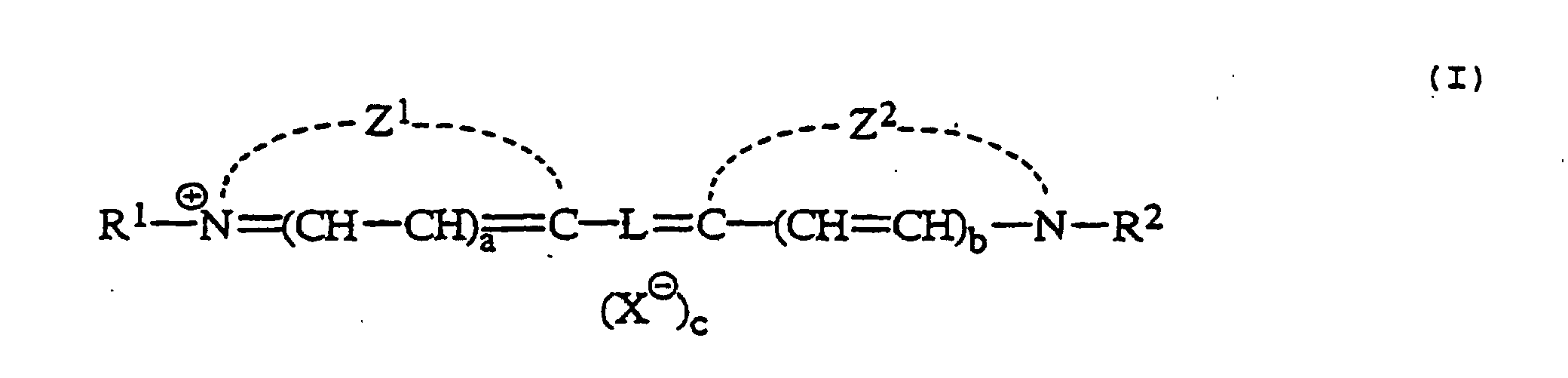
- Das Bildherstellungsverfahren wie in Anspruch 1 beansprucht, worin das Färbemittel ein Cyaninfarbstoff ist, der durch die Formel (Ib) wiedergegeben wird:worin jeder der Benzotringe von Z3 und Z4 mit einem anderen Benzolring kondensiert sein kann; jede der Gruppen R3 und R4 unabhängig eine Alkylgruppe, eine Alkenylgruppe oder eine Aralkylgruppe ist, jede der Gruppen R5, R6, R7 und R8 unabhängig eine Alkylgruppe ist, oder R5 und R6 oder R7 und R8 miteinander zur Bildung eines Rings kombiniert sind; R9 Wasserstoff, eine Alkylgruppe, ein Halogenatom, eine Arylgruppe, -NR14R15 (worin R14 eine Alkylgruppe oder eine Arylgruppe ist, R15 Wasserstoff, eine Alkylgruppe, eine Arylgruppe, eine Alkylsulfonylgruppe, eine Arylsulfonylgruppe oder eine Acylgruppe ist, oder R14 und R15 miteinander zur Bildung eines Stickstoff enthaltenden heterocyclischen Rings kombiniert sind), eine Alkylthiogruppe, eine Arylthiogruppe, eine Alkoxygruppe oder eine Aryloxygruppe ist; jede Gruppe R10 und R11 Wasserstoff ist, oder R10 und R11 miteinander zur Bildung eines fünfgliedrigen oder sechsgliedrigen Rings kombiniert sind; X ein Anion ist; und c 0 oder 1 ist.

- Das Bildherstellungsverfahren wie in Anspruch 1 beansprucht, worin das Färbemittel ein Lack-Cyaninfarbstoff ist, der durch die Formel (II) wiedergegeben wird:worin jede Gruppe Z1 und Z2 unabhängig eine nicht metallische Atomgruppe ist, die einen fünfgliedrigen oder sechsgliedrigen Stickstoff enthaltenden heterocyclischen Ring bildet, der mit einem anderen Ring kondensiert sein kann; jede Gruppe R1 und R2 unabhängig eine Alkylgruppe, eine Alkenylgruppe oder eine Aralkylgruppe ist; L eine Verbindungsgruppe mit konjugierten Doppelbindungen ist, gebildet durch eine Kombination von fünf, sieben oder neun Methingruppen; und jeder Buchstabe a und b unabhängig 0 oder 1 ist.

- Das Bildherstellungsverfahren wie in Anspruch 1 beansprucht, worin das Färbemittel in einer nicht lichtempfindlichen, hydrophilen Kolloidschicht enthalten ist, die als eine Schutzschicht fungiert.
- Das Bildherstellungsverfahren wie in Anspruch 1 beansprucht, worin das fotografische Material ein fotografisches Röntgen-Material ist, das wenigstens zwei Silberhalogenid-Emulsionsschichten enthält, wobei eine der Emulsionsschichten auf einer Seite des Trägers vorgesehen ist, und eine andere der Emulsionsschichten auf der gegenüberliegenden Seite des Trägers vorgesehen ist.
- Das Bildherstellungsverfahren wie in Anspruch 1 beansprucht, worin das fotografische Material Silberhalogenid in einer Menge von 1 bis 4 g pro m2, ausgedrückt als Silber, enthält.
Applications Claiming Priority (3)
| Application Number | Priority Date | Filing Date | Title |
|---|---|---|---|
| JP22798394 | 1994-09-22 | ||
| JP22798394 | 1994-09-22 | ||
| JP227983/94 | 1994-09-22 |
Publications (2)
| Publication Number | Publication Date |
|---|---|
| EP0703494A1 EP0703494A1 (de) | 1996-03-27 |
| EP0703494B1 true EP0703494B1 (de) | 2002-05-08 |
Family
ID=16869328
Family Applications (1)
| Application Number | Title | Priority Date | Filing Date |
|---|---|---|---|
| EP95114966A Expired - Lifetime EP0703494B1 (de) | 1994-09-22 | 1995-09-22 | Infrarot absorbierenden Farbstoff photographisches Silberhalogenidmaterial |
Country Status (3)
| Country | Link |
|---|---|
| US (2) | US5714307A (de) |
| EP (1) | EP0703494B1 (de) |
| DE (1) | DE69526617T2 (de) |
Families Citing this family (27)
| Publication number | Priority date | Publication date | Assignee | Title |
|---|---|---|---|---|
| JP3522941B2 (ja) * | 1995-12-26 | 2004-04-26 | 富士写真フイルム株式会社 | ハロゲン化銀写真感光材料 |
| US6245499B1 (en) * | 1996-04-30 | 2001-06-12 | Fuji Photo Film Co., Ltd. | Photothermographic material |
| US5783377A (en) * | 1996-09-04 | 1998-07-21 | Eastman Kodak Company | Infrared absorber dyes |
| JPH10207010A (ja) | 1997-01-20 | 1998-08-07 | Fuji Photo Film Co Ltd | ハロゲン化銀カラー写真感光材料 |
| JP3187738B2 (ja) * | 1997-02-17 | 2001-07-11 | 富士写真フイルム株式会社 | ヘプタメチンシアニン化合物、近赤外光吸収インク、近赤外光吸収シートおよびハロゲン化銀写真感光材料 |
| JPH10282605A (ja) * | 1997-04-09 | 1998-10-23 | Fuji Photo Film Co Ltd | ハロゲン化銀カラー写真感光材料 |
| US5966493A (en) | 1998-02-20 | 1999-10-12 | Molecular Optoelectronics Corporation | Fiber optic attenuators and attenuation systems |
| US6205280B1 (en) | 1998-08-25 | 2001-03-20 | Molecular Optoelectronics Corporation | Blockless fiber optic attenuators and attenuation systems employing dispersion controlled polymers |
| US6785461B2 (en) * | 1998-08-25 | 2004-08-31 | Molecular Optoelectronics Corp. | Blockless fiber optic attenuators and attenuation systems employing dispersion tailored polymers |
| US6191224B1 (en) * | 1998-08-25 | 2001-02-20 | Molecular Optoelectronics Corporation | Dispersion-controlled polymers for broadband fiber optic devices |
| US6301426B1 (en) | 1999-03-16 | 2001-10-09 | Molecular Optoelectronics Corporation | Mechanically adjustable fiber optic attenuator and method employing same |
| US6466729B1 (en) * | 2000-03-30 | 2002-10-15 | Molecular Optoelectronics Corporation | Controllable fiber optic attenuators employing tapered and/or etched fiber sections |
| US6483981B1 (en) | 2000-06-28 | 2002-11-19 | Molecular Optoelectronics Corp. | Single-channel attenuators |
| US6489399B1 (en) | 2000-07-31 | 2002-12-03 | Molecular Optoelectronics Corp. | Dye-appended polymers for broadband fiber optic devices |
| CA2423806C (en) * | 2000-09-29 | 2009-12-22 | Molecular Probes, Inc. | Modified carbocyanine dyes and their conjugates |
| US6681073B2 (en) | 2001-03-19 | 2004-01-20 | Molecular Optoelectronics Corporation | Fiber optic power control systems and methods |
| US6611649B2 (en) | 2001-03-19 | 2003-08-26 | Molecular Optoelectronics Corporation | Variable optical attenuator with polarization maintaining fiber |
| US6767677B2 (en) * | 2002-11-20 | 2004-07-27 | Eastman Kodak Company | Display element with a backprint comprising a squarine dye |
| US6689518B1 (en) * | 2002-11-20 | 2004-02-10 | Eastman Kodak Company | Photographic display elements comprising stable IR dye compositions for invisible marking |
| US7271265B2 (en) * | 2003-08-11 | 2007-09-18 | Invitrogen Corporation | Cyanine compounds and their application as quenching compounds |
| EP2607431B1 (de) | 2003-12-05 | 2016-08-24 | Life Technologies Corporation | Cyanin Farbstoffverbindungen |
| US7776529B2 (en) | 2003-12-05 | 2010-08-17 | Life Technologies Corporation | Methine-substituted cyanine dye compounds |
| JP5306811B2 (ja) | 2005-05-11 | 2013-10-02 | ライフ テクノロジーズ コーポレーション | 2本鎖dnaへの高い選択性を有する蛍光化学物質及びそれらの使用 |
| ATE391014T1 (de) * | 2005-06-21 | 2008-04-15 | Agfa Graphics Nv | Wärmeempfindliches bildaufzeichnungselement |
| US20090233247A1 (en) * | 2008-03-13 | 2009-09-17 | Zengerle Paul L | Infrared dye for silver halide-based photographic elements |
| KR102819929B1 (ko) | 2019-04-18 | 2025-06-11 | 삼성전자주식회사 | 화합물, 광학 필터, 이미지 센서, 카메라 모듈 및 전자 장치 |
| CN119912434B (zh) * | 2024-11-06 | 2025-12-16 | 四川大学 | 三官能咪唑二腈、吸波复合材料及其制备方法与应用 |
Family Cites Families (23)
| Publication number | Priority date | Publication date | Assignee | Title |
|---|---|---|---|---|
| GB387519A (en) * | 1931-03-09 | 1933-02-09 | Ig Farbenindustrie Ag | Filter layers for photographic purposes |
| US2095854A (en) | 1933-01-16 | 1937-10-12 | Eastman Kodak Co | Photographic emulsion containing tricarbocyanines |
| US3482978A (en) | 1966-08-25 | 1969-12-09 | Eastman Kodak Co | Carbocyanine filter dyes and sensitizers for silver halide emulsions |
| GB1563809A (en) | 1976-01-16 | 1980-04-02 | Agfa Gevaert | Light-absorbing dyes for silver halide material |
| JPS61123252A (ja) | 1984-11-19 | 1986-06-11 | Nec Corp | 多機能電話機の文字表示方式 |
| JPS61174540A (ja) * | 1985-01-29 | 1986-08-06 | Fuji Photo Film Co Ltd | ハロゲン化銀写真感光材料 |
| JPS62287250A (ja) * | 1986-06-06 | 1987-12-14 | Fuji Photo Film Co Ltd | カラ−画像形成方法およびハロゲン化銀カラ−写真感光材料 |
| JPS62299959A (ja) | 1986-06-20 | 1987-12-26 | Konica Corp | 放射線用ハロゲン化銀写真感光材料 |
| EP0294461B1 (de) | 1986-12-23 | 1991-10-23 | EASTMAN KODAK COMPANY (a New Jersey corporation) | Filterfarbstoffe in einer festpartikeldispersion für photographische zusammensetzungen |
| JPH087399B2 (ja) | 1988-04-18 | 1996-01-29 | 富士写真フイルム株式会社 | 赤外感光性ハロゲン化銀感光材料 |
| US4882265A (en) * | 1988-05-18 | 1989-11-21 | E. I. Du Pont De Nemours And Company | Infrared laser recording film |
| US4988611A (en) * | 1988-06-30 | 1991-01-29 | Eastman Kodak Company | Imaging utilizing a light-handleable photographic element having solid particle dispersion filter dye layer |
| JPH0816777B2 (ja) | 1988-10-13 | 1996-02-21 | 富士写真フイルム株式会社 | 画像形成方法 |
| US5063146A (en) * | 1989-03-02 | 1991-11-05 | Fuji Photo Film Co., Ltd. | Silver halide photographic material |
| JP2632727B2 (ja) | 1989-06-12 | 1997-07-23 | 富士写真フイルム株式会社 | ハロゲン化銀写真感光材料 |
| JPH03171136A (ja) | 1989-11-30 | 1991-07-24 | Fuji Photo Film Co Ltd | ハロゲン化銀写真感光材料 |
| JPH03211542A (ja) * | 1990-01-17 | 1991-09-17 | Fuji Photo Film Co Ltd | ハロゲン化銀写真感光材料 |
| DE69126085T2 (de) * | 1990-09-28 | 1997-08-28 | Fuji Photo Film Co Ltd | Wärmeentwickelbares lichtempfindliches Farbmaterial vom Farbdiffusionübertragungstyp |
| EP0556845B1 (de) * | 1992-02-21 | 1996-06-05 | Fuji Photo Film Co., Ltd. | Verfahren zum Verarbeiten eines photographischen Silberhalogenidmaterials |
| JP2884281B2 (ja) * | 1992-07-03 | 1999-04-19 | 富士写真フイルム株式会社 | ハロゲン化銀写真感光材料 |
| JP2955803B2 (ja) | 1992-07-22 | 1999-10-04 | 富士写真フイルム株式会社 | ハロゲン化銀写真感光材料 |
| JP2811516B2 (ja) | 1992-08-19 | 1998-10-15 | 富士写真フイルム株式会社 | ハロゲン化銀写真感光材料 |
| JP3444646B2 (ja) * | 1994-03-16 | 2003-09-08 | 富士写真フイルム株式会社 | ハロゲン化銀写真感光材料 |
-
1995
- 1995-09-22 DE DE69526617T patent/DE69526617T2/de not_active Expired - Fee Related
- 1995-09-22 EP EP95114966A patent/EP0703494B1/de not_active Expired - Lifetime
- 1995-09-22 US US08/532,880 patent/US5714307A/en not_active Expired - Fee Related
-
1997
- 1997-11-28 US US08/980,304 patent/US5853969A/en not_active Expired - Fee Related
Also Published As
| Publication number | Publication date |
|---|---|
| US5853969A (en) | 1998-12-29 |
| DE69526617T2 (de) | 2002-08-29 |
| US5714307A (en) | 1998-02-03 |
| EP0703494A1 (de) | 1996-03-27 |
| DE69526617D1 (de) | 2002-06-13 |
Similar Documents
| Publication | Publication Date | Title |
|---|---|---|
| EP0703494B1 (de) | Infrarot absorbierenden Farbstoff photographisches Silberhalogenidmaterial | |
| US4803150A (en) | Radiographic element exhibiting reduced crossover | |
| EP0276566B1 (de) | Radiographisches Element mit reduziertem Zwischenbildeffekt | |
| EP0391405A2 (de) | Photographisches Silberhalogenidmaterial und Verarbeitungsmethode dafür | |
| JP3187738B2 (ja) | ヘプタメチンシアニン化合物、近赤外光吸収インク、近赤外光吸収シートおよびハロゲン化銀写真感光材料 | |
| GB2140928A (en) | Silver halide photographic materials | |
| DE69120173T2 (de) | Silberhalogenidemulsion | |
| US5344749A (en) | Filter dyes for rapid processing applications | |
| US5380634A (en) | Filter dyes for rapid processing applications | |
| JP3616173B2 (ja) | ハロゲン化銀写真感光材料および画像形成方法 | |
| EP0854382B1 (de) | Heptamethincyaninverbindung | |
| JPH0731386B2 (ja) | 直接ポジ型ハロゲン化銀写真感光材料 | |
| US6342338B1 (en) | Silver halide photographic material exhibiting increased covering power and “colder” blue-black image tone | |
| JPH08333519A (ja) | 固体微粒子分散状のシアニン染料 | |
| EP0587230B1 (de) | Photographisches Element,das einen Filterfarbstoff enthält, für Schnellverarbeitungs-Verwendungen | |
| EP0587229B1 (de) | Photographisches Element,das einen Filterfarbstoff enthält, für Schnellverarbeitungs-Verwendungen | |
| JPH08245902A (ja) | シアニン化合物の固体微粒子分散物 | |
| JPH03138640A (ja) | ハロゲン化銀写真感光材料及びその位置検出方法 | |
| JPH0990547A (ja) | ハロゲン化銀写真感光材料 | |
| EP0953867B1 (de) | Verfahren zur spektralen Sensibilisierung von tafelförmigen Silberhalogenidkörnern | |
| JPH0895197A (ja) | ハロゲン化銀写真感光材料 | |
| EP1103847B1 (de) | Photographisches Silberhalogenid-Filmmaterial mit erhöhter Deckkraft und einem "kälteren" blauschwarzen Bildton | |
| JPH08295821A (ja) | シアニン化合物の固体微粒子分散物 | |
| JPH04180057A (ja) | ハロゲン化銀写真感光材料 | |
| JP2739369B2 (ja) | ハロゲン化銀写真感光材料 |
Legal Events
| Date | Code | Title | Description |
|---|---|---|---|
| PUAI | Public reference made under article 153(3) epc to a published international application that has entered the european phase |
Free format text: ORIGINAL CODE: 0009012 |
|
| AK | Designated contracting states |
Kind code of ref document: A1 Designated state(s): DE FR GB NL |
|
| 17P | Request for examination filed |
Effective date: 19960703 |
|
| 17Q | First examination report despatched |
Effective date: 20000125 |
|
| GRAG | Despatch of communication of intention to grant |
Free format text: ORIGINAL CODE: EPIDOS AGRA |
|
| GRAG | Despatch of communication of intention to grant |
Free format text: ORIGINAL CODE: EPIDOS AGRA |
|
| GRAH | Despatch of communication of intention to grant a patent |
Free format text: ORIGINAL CODE: EPIDOS IGRA |
|
| REG | Reference to a national code |
Ref country code: GB Ref legal event code: IF02 |
|
| GRAH | Despatch of communication of intention to grant a patent |
Free format text: ORIGINAL CODE: EPIDOS IGRA |
|
| GRAA | (expected) grant |
Free format text: ORIGINAL CODE: 0009210 |
|
| AK | Designated contracting states |
Kind code of ref document: B1 Designated state(s): DE FR GB NL |
|
| PG25 | Lapsed in a contracting state [announced via postgrant information from national office to epo] |
Ref country code: NL Free format text: LAPSE BECAUSE OF FAILURE TO SUBMIT A TRANSLATION OF THE DESCRIPTION OR TO PAY THE FEE WITHIN THE PRESCRIBED TIME-LIMIT Effective date: 20020508 |
|
| REF | Corresponds to: |
Ref document number: 69526617 Country of ref document: DE Date of ref document: 20020613 |
|
| NLV1 | Nl: lapsed or annulled due to failure to fulfill the requirements of art. 29p and 29m of the patents act | ||
| ET | Fr: translation filed | ||
| PLBE | No opposition filed within time limit |
Free format text: ORIGINAL CODE: 0009261 |
|
| STAA | Information on the status of an ep patent application or granted ep patent |
Free format text: STATUS: NO OPPOSITION FILED WITHIN TIME LIMIT |
|
| 26N | No opposition filed |
Effective date: 20030211 |
|
| REG | Reference to a national code |
Ref country code: GB Ref legal event code: 732E |
|
| REG | Reference to a national code |
Ref country code: FR Ref legal event code: TP Ref country code: FR Ref legal event code: CD |
|
| PGFP | Annual fee paid to national office [announced via postgrant information from national office to epo] |
Ref country code: FR Payment date: 20080915 Year of fee payment: 14 |
|
| PGFP | Annual fee paid to national office [announced via postgrant information from national office to epo] |
Ref country code: GB Payment date: 20080924 Year of fee payment: 14 |
|
| PGFP | Annual fee paid to national office [announced via postgrant information from national office to epo] |
Ref country code: DE Payment date: 20081002 Year of fee payment: 14 |
|
| GBPC | Gb: european patent ceased through non-payment of renewal fee |
Effective date: 20090922 |
|
| REG | Reference to a national code |
Ref country code: FR Ref legal event code: ST Effective date: 20100531 |
|
| PG25 | Lapsed in a contracting state [announced via postgrant information from national office to epo] |
Ref country code: FR Free format text: LAPSE BECAUSE OF NON-PAYMENT OF DUE FEES Effective date: 20090930 Ref country code: DE Free format text: LAPSE BECAUSE OF NON-PAYMENT OF DUE FEES Effective date: 20100401 |
|
| PG25 | Lapsed in a contracting state [announced via postgrant information from national office to epo] |
Ref country code: GB Free format text: LAPSE BECAUSE OF NON-PAYMENT OF DUE FEES Effective date: 20090922 |