EP0777313B1 - Moteur et appareil électronique de montage de pièces, incorporant le moteur - Google Patents
Moteur et appareil électronique de montage de pièces, incorporant le moteur Download PDFInfo
- Publication number
- EP0777313B1 EP0777313B1 EP96118918A EP96118918A EP0777313B1 EP 0777313 B1 EP0777313 B1 EP 0777313B1 EP 96118918 A EP96118918 A EP 96118918A EP 96118918 A EP96118918 A EP 96118918A EP 0777313 B1 EP0777313 B1 EP 0777313B1
- Authority
- EP
- European Patent Office
- Prior art keywords
- rotor
- motor
- bearings
- holding members
- stator
- Prior art date
- Legal status (The legal status is an assumption and is not a legal conclusion. Google has not performed a legal analysis and makes no representation as to the accuracy of the status listed.)
- Expired - Lifetime
Links
Images


Classifications
-
- H—ELECTRICITY
- H02—GENERATION; CONVERSION OR DISTRIBUTION OF ELECTRIC POWER
- H02K—DYNAMO-ELECTRIC MACHINES
- H02K1/00—Details of the magnetic circuit
- H02K1/06—Details of the magnetic circuit characterised by the shape, form or construction
- H02K1/12—Stationary parts of the magnetic circuit
- H02K1/16—Stator cores with slots for windings
-
- H—ELECTRICITY
- H02—GENERATION; CONVERSION OR DISTRIBUTION OF ELECTRIC POWER
- H02K—DYNAMO-ELECTRIC MACHINES
- H02K5/00—Casings; Enclosures; Supports
- H02K5/04—Casings or enclosures characterised by the shape, form or construction thereof
- H02K5/15—Mounting arrangements for bearing-shields or end plates
-
- H—ELECTRICITY
- H02—GENERATION; CONVERSION OR DISTRIBUTION OF ELECTRIC POWER
- H02K—DYNAMO-ELECTRIC MACHINES
- H02K5/00—Casings; Enclosures; Supports
- H02K5/04—Casings or enclosures characterised by the shape, form or construction thereof
- H02K5/16—Means for supporting bearings, e.g. insulating supports or means for fitting bearings in the bearing-shields
- H02K5/173—Means for supporting bearings, e.g. insulating supports or means for fitting bearings in the bearing-shields using bearings with rolling contact, e.g. ball bearings
- H02K5/1732—Means for supporting bearings, e.g. insulating supports or means for fitting bearings in the bearing-shields using bearings with rolling contact, e.g. ball bearings radially supporting the rotary shaft at both ends of the rotor
-
- H—ELECTRICITY
- H02—GENERATION; CONVERSION OR DISTRIBUTION OF ELECTRIC POWER
- H02K—DYNAMO-ELECTRIC MACHINES
- H02K7/00—Arrangements for handling mechanical energy structurally associated with dynamo-electric machines, e.g. structural association with mechanical driving motors or auxiliary dynamo-electric machines
- H02K7/08—Structural association with bearings
- H02K7/086—Structural association with bearings radially supporting the rotor around a fixed spindle; radially supporting the rotor directly
- H02K7/088—Structural association with bearings radially supporting the rotor around a fixed spindle; radially supporting the rotor directly radially supporting the rotor directly
-
- H—ELECTRICITY
- H02—GENERATION; CONVERSION OR DISTRIBUTION OF ELECTRIC POWER
- H02K—DYNAMO-ELECTRIC MACHINES
- H02K37/00—Motors with rotor rotating step by step and without interrupter or commutator driven by the rotor, e.g. stepping motors
- H02K37/10—Motors with rotor rotating step by step and without interrupter or commutator driven by the rotor, e.g. stepping motors of permanent magnet type
- H02K37/12—Motors with rotor rotating step by step and without interrupter or commutator driven by the rotor, e.g. stepping motors of permanent magnet type with stationary armatures and rotating magnets
- H02K37/14—Motors with rotor rotating step by step and without interrupter or commutator driven by the rotor, e.g. stepping motors of permanent magnet type with stationary armatures and rotating magnets with magnets rotating within the armatures
-
- H—ELECTRICITY
- H02—GENERATION; CONVERSION OR DISTRIBUTION OF ELECTRIC POWER
- H02K—DYNAMO-ELECTRIC MACHINES
- H02K7/00—Arrangements for handling mechanical energy structurally associated with dynamo-electric machines, e.g. structural association with mechanical driving motors or auxiliary dynamo-electric machines
- H02K7/14—Structural association with mechanical loads, e.g. with hand-held machine tools or fans
Definitions
- the rotary table is intermittently rotated to thereby carry electronic parts picked up by a selected one of the sucking nozzles of each of the mounting heads from the parts-feeding station to the parts-mounting station.
- a stepping motor for rotating the mounting head through predetermined angles about the rotational axis thereof to thereby enable selection of a sucking nozzle as desired.
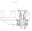
- the construction of the conventional stepping motor is shown in FIG. 1.
Landscapes
- Engineering & Computer Science (AREA)
- Power Engineering (AREA)
- Iron Core Of Rotating Electric Machines (AREA)
- Motor Or Generator Frames (AREA)
- Supply And Installment Of Electrical Components (AREA)
Claims (6)
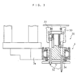
- Moteur comprenant un rotor (5) et un stator (6) comprenant un noyau de stator (61) formé d'un laminé en tôles d'acier; des membres de maintien (62) disposés à des extrémités opposées dudit laminé en tôles d'acier dudit noyau de stator (61); des boulons (64) attachant lesdits membres de maintien (62) l'un à l'autre; et une paire de paliers (7) disposée entre ledit rotor (5) et lesdits membres de maintien (62) pour supporter en rotation ledit rotor (5), chacun des paliers de ladite paire de paliers (7) ayant un anneau intérieur, un anneau extérieur et des billes d'acier,
caractérisé en ce que
soit ledit rotor (5), soit lesdits membres de maintien (62) sont prévu d'un poussoir (72) pour solliciter soit ledit anneau extérieur, soit ledit anneau intérieur de ladite paire de paliers (7) vers ledites billes d'acier. - Moteur selon la revendication 1, caractérisé en ce que ledit poussoir (72') comprend un moyen de retenue (83) installé sur une partie périphérique d'une extrémité de l'un desdits membres de maintien (62) ainsi que des boulons (84) attachés audit un desdits membres de maintien (62) pour solliciter ledit moyen métallique de retenue (83) contre ledit un desdits membres de maintien (62).
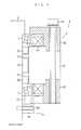
- Moteur comprenant un rotor (5) et un stator (6'), ledit stator (6') comportant un noyau de stator (61') formé d'un laminé en tôles d'acier et disposé d'une manière opposée audit rotor (5); des membres de maintien (62') disposés à des extrémités opposées dudit laminé en tôles d'acier dudit noyau de stator (61'); des boulons (64) attachant lesdits membres de maintien (62') l'un à l'autre; et une paire de paliers (7) supportant en rotation ledit rotor (5), chacun des paliers de ladite paire de paliers (7) ayant un anneau intérieur, un anneau extérieur et des billes d'acier,
caractérisé en ce que
ladite paire de paliers (7) est interposée entre ledit rotor (5) et ledit noyau de stator (61'); et
soit ledit rotor (5), soit lesdits membres de maintien (62') sont prévu d'un poussoir (72) pour solliciter soit ledit anneau extérieur, soit ledit anneau intérieur de ladite paire de paliers (7) vers ledites billes d'acier. - Moteur selon la revendication 1 ou 3, caractérisé en ce que ledit poussoir (72) comprend une pluralité de boulons (80) logés dans une paroi latérale dudit rotor (5) à des intervalles d'espace prédéterminés, et une pluralité d'écrous excentriques (81) chacun vissé sur un boulon correspondant de ladite pluralité de boulons (80) pour être mis en contact avec soit ledit anneau extérieur, soit ledit anneau intérieur desdits paliers (7) à une partie de surface périphérique de ces-derniers.
- Appareil pour le montage de composants électroniques, comportant des buses aspirantes (32) pour ramasser un composant électronique par aspiration; des têtes de montage (31) pour supporter en rotation lesdites buses d'aspiration (32); un dispositif porteur (3) pour porter lesdites têtes de montage (31); et des moteurs (4) pour entrainer en rotation respective lesdites têtes de montage (31), lesdits moteurs (4) comportant chacun un rotor (5) solidaire d'une tête correspondante desdites têtes de montage (31) et un stator (6) attaché audit dispositif porteur (3), ledit moteur (4) étant un moteur selon la revendivation 1 ou 2.
- Appareil pour le montage de composants électroniques, comportant des buses aspirantes (32) pour ramasser un composant électronique par aspiration; des têtes de montage (31) pour supporter en rotation lesdites buses d'aspiration (32); un dispositif porteur (3) pour porter lesdites têtes de montage (31); et des moteurs (4) pour entrainer en rotation respective lesdites têtes de montage (31), lesdits moteurs (4) comportant chacun un rotor (5) solidaire d'une tête correspondante desdites têtes de montage (31) et un stator (6) attaché audit dispositif porteur (3), ledit moteur (4) étant un moteur selon la revendivation 3 ou 4.
Applications Claiming Priority (6)
| Application Number | Priority Date | Filing Date | Title |
|---|---|---|---|
| JP33573295 | 1995-11-30 | ||
| JP335731/95 | 1995-11-30 | ||
| JP7335731A JPH09163711A (ja) | 1995-11-30 | 1995-11-30 | モータおよびこれを用いた電子部品装着装置 |
| JP7335732A JPH09163712A (ja) | 1995-11-30 | 1995-11-30 | モータおよびこれを用いた電子部品装着装置 |
| JP335732/95 | 1995-11-30 | ||
| JP33573195 | 1995-11-30 |
Publications (3)
| Publication Number | Publication Date |
|---|---|
| EP0777313A2 EP0777313A2 (fr) | 1997-06-04 |
| EP0777313A3 EP0777313A3 (fr) | 1998-03-04 |
| EP0777313B1 true EP0777313B1 (fr) | 2002-04-03 |
Family
ID=26575259
Family Applications (1)
| Application Number | Title | Priority Date | Filing Date |
|---|---|---|---|
| EP96118918A Expired - Lifetime EP0777313B1 (fr) | 1995-11-30 | 1996-11-26 | Moteur et appareil électronique de montage de pièces, incorporant le moteur |
Country Status (4)
| Country | Link |
|---|---|
| US (1) | US5767598A (fr) |
| EP (1) | EP0777313B1 (fr) |
| KR (1) | KR100435175B1 (fr) |
| DE (1) | DE69620355T2 (fr) |
Families Citing this family (10)
| Publication number | Priority date | Publication date | Assignee | Title |
|---|---|---|---|---|
| US6101707A (en) * | 1998-03-03 | 2000-08-15 | Sanyo Electric Co., Ltd. | Mounting head for electronic component-mounting apparatus |
| US6503039B2 (en) | 2000-12-12 | 2003-01-07 | Illinois Tool Works Inc. | Off-set adjusting nut |
| JP2005335535A (ja) * | 2004-05-27 | 2005-12-08 | Sanyo Electric Co Ltd | 電動車輪用ハブユニット及び該ハブユニットを具えた乗物 |
| JP4504157B2 (ja) * | 2004-10-29 | 2010-07-14 | 株式会社日立ハイテクインスツルメンツ | 電子部品装着装置の装着ヘッド |
| US7755242B2 (en) * | 2005-12-05 | 2010-07-13 | Lg Electronics Inc. | Motor, method for manufacturing the same, and washing machine using the same |
| JP2007159332A (ja) * | 2005-12-08 | 2007-06-21 | Toyota Motor Corp | 回転電機 |
| JP5898876B2 (ja) * | 2011-07-26 | 2016-04-06 | 山洋電気株式会社 | 電気機器 |
| US20140167559A1 (en) * | 2012-12-14 | 2014-06-19 | Deere & Company | Electric machine stator securing method |
| GB2538516B (en) | 2015-05-19 | 2021-09-29 | Time To Act Ltd | Method of construction for permanent magnet generator |
| US11637477B2 (en) * | 2019-01-02 | 2023-04-25 | Joseph Gentile | Rotating machine |
Family Cites Families (14)
| Publication number | Priority date | Publication date | Assignee | Title |
|---|---|---|---|---|
| US2173561A (en) * | 1937-09-24 | 1939-09-19 | Clarence T Olson | Take-up device for antifriction bearings |
| GB968871A (en) * | 1960-01-20 | 1964-09-02 | Electrolux Ab | Improvements in bearing shields for electric motors |
| FR1320919A (fr) * | 1962-02-02 | 1963-03-15 | Dispositif de suspension pour rotor de moteur électrique | |
| US3900232A (en) * | 1973-09-26 | 1975-08-19 | Temper Corp | Arrangement for preloading bearings |
| DE2829027A1 (de) * | 1978-07-01 | 1980-01-10 | Bosch Gmbh Robert | Elektrische maschine |
| US4361953A (en) * | 1978-10-31 | 1982-12-07 | Emerson Electric Co. | Method of securing end shields to the stator assembly of a dynamoelectric machine |
| GB2113924B (en) * | 1982-01-08 | 1986-11-12 | Black & Decker Inc | Improvements in or relating to electric motors and components therefor |
| JPS58144553A (ja) * | 1982-02-19 | 1983-08-27 | Nissan Motor Co Ltd | モ−タ |
| JPS61121729A (ja) * | 1984-11-14 | 1986-06-09 | Fanuc Ltd | 液冷モ−タ |
| JPH01103133A (ja) * | 1987-10-14 | 1989-04-20 | Fanuc Ltd | 無溶接・有脚型のモータ構造 |
| FR2648286B1 (fr) * | 1989-06-08 | 1992-02-07 | Rks | Couronne d'orientation a roulement a moteur integre |
| JPH0322843A (ja) * | 1989-06-16 | 1991-01-31 | Fanuc Ltd | モータのころがり軸受の予圧付与装置 |
| JPH0549200A (ja) * | 1991-08-08 | 1993-02-26 | Fanuc Ltd | ステータ一体形ハウジングを備えた誘導モータ |
| JP2823481B2 (ja) | 1993-05-26 | 1998-11-11 | 三洋電機株式会社 | 電子部品自動装着装置 |
-
1996
- 1996-11-26 EP EP96118918A patent/EP0777313B1/fr not_active Expired - Lifetime
- 1996-11-26 DE DE69620355T patent/DE69620355T2/de not_active Expired - Lifetime
- 1996-11-26 US US08/756,757 patent/US5767598A/en not_active Expired - Lifetime
- 1996-11-29 KR KR1019960059390A patent/KR100435175B1/ko not_active Expired - Fee Related
Also Published As
| Publication number | Publication date |
|---|---|
| KR970031159A (ko) | 1997-06-26 |
| KR100435175B1 (ko) | 2004-08-25 |
| EP0777313A2 (fr) | 1997-06-04 |
| EP0777313A3 (fr) | 1998-03-04 |
| DE69620355T2 (de) | 2002-11-28 |
| DE69620355D1 (de) | 2002-05-08 |
| US5767598A (en) | 1998-06-16 |
Similar Documents
| Publication | Publication Date | Title |
|---|---|---|
| EP0777313B1 (fr) | Moteur et appareil électronique de montage de pièces, incorporant le moteur | |
| US4540906A (en) | Stator assembly for permanent magnet rotary device | |
| KR101147966B1 (ko) | 인쇄회로기판의 삽입장치를 위한 공급장치 | |
| CN114536003B (zh) | 组装设备 | |
| JPS58500744A (ja) | 位置設定装置 | |
| US7036205B2 (en) | Method of manufacturing stator for brushless motors | |
| US6215210B1 (en) | Motor, structure of stator of the motor and assembly method of the stator | |
| JP3348641B2 (ja) | 自動組付け装置 | |
| CN100390034C (zh) | 送料装置及采用该送料装置的元器件装配装置 | |
| US7732957B2 (en) | Brushless motor | |
| WO2022113694A1 (fr) | Dispositif de table rotative | |
| EP0597678A1 (fr) | Moteur électrique du type à palier intégré | |
| JPH09163712A (ja) | モータおよびこれを用いた電子部品装着装置 | |
| JPH09163711A (ja) | モータおよびこれを用いた電子部品装着装置 | |
| JP2993401B2 (ja) | ワークの装着装置および装着方法 | |
| JPH05344701A (ja) | ブラシレスモータ | |
| CN118523575B (zh) | 一种无刷直流电机端盖自动组装设备 | |
| JP4277569B2 (ja) | 直動ステージ | |
| EP4697572A1 (fr) | Ensemble d'un rotor d'une machine électrique | |
| US11552031B2 (en) | High precision bonding apparatus comprising heater | |
| JPH05966Y2 (fr) | ||
| JPH11145687A (ja) | 電子部品実装装置 | |
| JPH0638466A (ja) | モータの製造方法およびそれに使用されるモータの組立装置 | |
| JPH09298867A (ja) | ステッピングモータ | |
| JP3246706B2 (ja) | 軸受保持装置 |
Legal Events
| Date | Code | Title | Description |
|---|---|---|---|
| PUAI | Public reference made under article 153(3) epc to a published international application that has entered the european phase |
Free format text: ORIGINAL CODE: 0009012 |
|
| AK | Designated contracting states |
Kind code of ref document: A2 Designated state(s): DE GB NL |
|
| PUAL | Search report despatched |
Free format text: ORIGINAL CODE: 0009013 |
|
| AK | Designated contracting states |
Kind code of ref document: A3 Designated state(s): DE GB NL |
|
| 17P | Request for examination filed |
Effective date: 19980604 |
|
| 17Q | First examination report despatched |
Effective date: 19990915 |
|
| GRAG | Despatch of communication of intention to grant |
Free format text: ORIGINAL CODE: EPIDOS AGRA |
|
| GRAG | Despatch of communication of intention to grant |
Free format text: ORIGINAL CODE: EPIDOS AGRA |
|
| GRAH | Despatch of communication of intention to grant a patent |
Free format text: ORIGINAL CODE: EPIDOS IGRA |
|
| GRAH | Despatch of communication of intention to grant a patent |
Free format text: ORIGINAL CODE: EPIDOS IGRA |
|
| REG | Reference to a national code |
Ref country code: GB Ref legal event code: IF02 |
|
| GRAA | (expected) grant |
Free format text: ORIGINAL CODE: 0009210 |
|
| AK | Designated contracting states |
Kind code of ref document: B1 Designated state(s): DE GB NL |
|
| REF | Corresponds to: |
Ref document number: 69620355 Country of ref document: DE Date of ref document: 20020508 |
|
| PG25 | Lapsed in a contracting state [announced via postgrant information from national office to epo] |
Ref country code: GB Free format text: LAPSE BECAUSE OF NON-PAYMENT OF DUE FEES Effective date: 20021126 |
|
| PLBE | No opposition filed within time limit |
Free format text: ORIGINAL CODE: 0009261 |
|
| STAA | Information on the status of an ep patent application or granted ep patent |
Free format text: STATUS: NO OPPOSITION FILED WITHIN TIME LIMIT |
|
| 26N | No opposition filed |
Effective date: 20030106 |
|
| GBPC | Gb: european patent ceased through non-payment of renewal fee | ||
| NLS | Nl: assignments of ep-patents |
Owner name: HITACHI HIGH-TECH INSTRUMENTS CO., LTD. |
|
| PGFP | Annual fee paid to national office [announced via postgrant information from national office to epo] |
Ref country code: DE Payment date: 20101124 Year of fee payment: 15 |
|
| PGFP | Annual fee paid to national office [announced via postgrant information from national office to epo] |
Ref country code: NL Payment date: 20111122 Year of fee payment: 16 |
|
| REG | Reference to a national code |
Ref country code: NL Ref legal event code: V1 Effective date: 20130601 |
|
| PG25 | Lapsed in a contracting state [announced via postgrant information from national office to epo] |
Ref country code: NL Free format text: LAPSE BECAUSE OF NON-PAYMENT OF DUE FEES Effective date: 20130601 |
|
| REG | Reference to a national code |
Ref country code: DE Ref legal event code: R119 Ref document number: 69620355 Country of ref document: DE Effective date: 20130601 |
|
| PG25 | Lapsed in a contracting state [announced via postgrant information from national office to epo] |
Ref country code: DE Free format text: LAPSE BECAUSE OF NON-PAYMENT OF DUE FEES Effective date: 20130601 |