EP0802354A2 - Vorrichtung und Verfahren zur Steuerung eines Automatikgetriebes von einem Kraftfahrzeug - Google Patents
Vorrichtung und Verfahren zur Steuerung eines Automatikgetriebes von einem Kraftfahrzeug Download PDFInfo
- Publication number
- EP0802354A2 EP0802354A2 EP97106465A EP97106465A EP0802354A2 EP 0802354 A2 EP0802354 A2 EP 0802354A2 EP 97106465 A EP97106465 A EP 97106465A EP 97106465 A EP97106465 A EP 97106465A EP 0802354 A2 EP0802354 A2 EP 0802354A2
- Authority
- EP
- European Patent Office
- Prior art keywords
- value
- friction engagement
- friction
- torque
- time
- Prior art date
- Legal status (The legal status is an assumption and is not a legal conclusion. Google has not performed a legal analysis and makes no representation as to the accuracy of the status listed.)
- Granted
Links
- 230000005540 biological transmission Effects 0.000 title claims abstract description 51
- 238000000034 method Methods 0.000 title claims description 17
- 230000007423 decrease Effects 0.000 claims abstract 5
- 230000007246 mechanism Effects 0.000 claims description 31
- 230000001133 acceleration Effects 0.000 claims description 27
- 230000003247 decreasing effect Effects 0.000 claims description 6
- 230000000694 effects Effects 0.000 claims 4
- 238000001514 detection method Methods 0.000 description 14
- 230000001276 controlling effect Effects 0.000 description 13
- 238000012937 correction Methods 0.000 description 6
- 238000010586 diagram Methods 0.000 description 6
- 238000001914 filtration Methods 0.000 description 6
- 239000000446 fuel Substances 0.000 description 5
- 238000002347 injection Methods 0.000 description 4
- 239000007924 injection Substances 0.000 description 4
- 238000012545 processing Methods 0.000 description 4
- 238000007796 conventional method Methods 0.000 description 2
- 230000003111 delayed effect Effects 0.000 description 2
- 238000002474 experimental method Methods 0.000 description 2
- 230000002123 temporal effect Effects 0.000 description 2
- 238000004891 communication Methods 0.000 description 1
- 230000006870 function Effects 0.000 description 1
- 230000002035 prolonged effect Effects 0.000 description 1
- 230000001105 regulatory effect Effects 0.000 description 1
- 238000007493 shaping process Methods 0.000 description 1
Images


Classifications
-
- F—MECHANICAL ENGINEERING; LIGHTING; HEATING; WEAPONS; BLASTING
- F16—ENGINEERING ELEMENTS AND UNITS; GENERAL MEASURES FOR PRODUCING AND MAINTAINING EFFECTIVE FUNCTIONING OF MACHINES OR INSTALLATIONS; THERMAL INSULATION IN GENERAL
- F16H—GEARING
- F16H59/00—Control inputs to control units of change-speed- or reversing-gearings for conveying rotary motion
- F16H59/14—Inputs being a function of torque or torque demand
- F16H59/141—Inputs being a function of torque or torque demand of rate of change of torque or torque demand
-
- F—MECHANICAL ENGINEERING; LIGHTING; HEATING; WEAPONS; BLASTING
- F16—ENGINEERING ELEMENTS AND UNITS; GENERAL MEASURES FOR PRODUCING AND MAINTAINING EFFECTIVE FUNCTIONING OF MACHINES OR INSTALLATIONS; THERMAL INSULATION IN GENERAL
- F16H—GEARING
- F16H59/00—Control inputs to control units of change-speed- or reversing-gearings for conveying rotary motion
- F16H59/14—Inputs being a function of torque or torque demand
- F16H59/16—Dynamometric measurement of torque
-
- F—MECHANICAL ENGINEERING; LIGHTING; HEATING; WEAPONS; BLASTING
- F16—ENGINEERING ELEMENTS AND UNITS; GENERAL MEASURES FOR PRODUCING AND MAINTAINING EFFECTIVE FUNCTIONING OF MACHINES OR INSTALLATIONS; THERMAL INSULATION IN GENERAL
- F16H—GEARING
- F16H59/00—Control inputs to control units of change-speed- or reversing-gearings for conveying rotary motion
- F16H59/36—Inputs being a function of speed
-
- F—MECHANICAL ENGINEERING; LIGHTING; HEATING; WEAPONS; BLASTING
- F16—ENGINEERING ELEMENTS AND UNITS; GENERAL MEASURES FOR PRODUCING AND MAINTAINING EFFECTIVE FUNCTIONING OF MACHINES OR INSTALLATIONS; THERMAL INSULATION IN GENERAL
- F16H—GEARING
- F16H59/00—Control inputs to control units of change-speed- or reversing-gearings for conveying rotary motion
- F16H59/36—Inputs being a function of speed
- F16H59/38—Inputs being a function of speed of gearing elements
- F16H59/42—Input shaft speed
-
- F—MECHANICAL ENGINEERING; LIGHTING; HEATING; WEAPONS; BLASTING
- F16—ENGINEERING ELEMENTS AND UNITS; GENERAL MEASURES FOR PRODUCING AND MAINTAINING EFFECTIVE FUNCTIONING OF MACHINES OR INSTALLATIONS; THERMAL INSULATION IN GENERAL
- F16H—GEARING
- F16H59/00—Control inputs to control units of change-speed- or reversing-gearings for conveying rotary motion
- F16H59/48—Inputs being a function of acceleration
-
- F—MECHANICAL ENGINEERING; LIGHTING; HEATING; WEAPONS; BLASTING
- F16—ENGINEERING ELEMENTS AND UNITS; GENERAL MEASURES FOR PRODUCING AND MAINTAINING EFFECTIVE FUNCTIONING OF MACHINES OR INSTALLATIONS; THERMAL INSULATION IN GENERAL
- F16H—GEARING
- F16H61/00—Control functions within control units of change-speed- or reversing-gearings for conveying rotary motion ; Control of exclusively fluid gearing, friction gearing, gearings with endless flexible members or other particular types of gearing
- F16H61/04—Smoothing ratio shift
- F16H61/06—Smoothing ratio shift by controlling rate of change of fluid pressure
- F16H61/061—Smoothing ratio shift by controlling rate of change of fluid pressure using electric control means
-
- F—MECHANICAL ENGINEERING; LIGHTING; HEATING; WEAPONS; BLASTING
- F16—ENGINEERING ELEMENTS AND UNITS; GENERAL MEASURES FOR PRODUCING AND MAINTAINING EFFECTIVE FUNCTIONING OF MACHINES OR INSTALLATIONS; THERMAL INSULATION IN GENERAL
- F16H—GEARING
- F16H63/00—Control outputs from the control unit to change-speed- or reversing-gearings for conveying rotary motion or to other devices than the final output mechanism
- F16H63/40—Control outputs from the control unit to change-speed- or reversing-gearings for conveying rotary motion or to other devices than the final output mechanism comprising signals other than signals for actuating the final output mechanisms
- F16H63/50—Signals to an engine or motor
- F16H63/502—Signals to an engine or motor for smoothing gear shifts
-
- B—PERFORMING OPERATIONS; TRANSPORTING
- B60—VEHICLES IN GENERAL
- B60W—CONJOINT CONTROL OF VEHICLE SUB-UNITS OF DIFFERENT TYPE OR DIFFERENT FUNCTION; CONTROL SYSTEMS SPECIALLY ADAPTED FOR HYBRID VEHICLES; ROAD VEHICLE DRIVE CONTROL SYSTEMS FOR PURPOSES NOT RELATED TO THE CONTROL OF A PARTICULAR SUB-UNIT
- B60W2510/00—Input parameters relating to a particular sub-units
- B60W2510/10—Change speed gearings
- B60W2510/105—Output torque
-
- B—PERFORMING OPERATIONS; TRANSPORTING
- B60—VEHICLES IN GENERAL
- B60W—CONJOINT CONTROL OF VEHICLE SUB-UNITS OF DIFFERENT TYPE OR DIFFERENT FUNCTION; CONTROL SYSTEMS SPECIALLY ADAPTED FOR HYBRID VEHICLES; ROAD VEHICLE DRIVE CONTROL SYSTEMS FOR PURPOSES NOT RELATED TO THE CONTROL OF A PARTICULAR SUB-UNIT
- B60W2520/00—Input parameters relating to overall vehicle dynamics
- B60W2520/10—Longitudinal speed
- B60W2520/105—Longitudinal acceleration
-
- F—MECHANICAL ENGINEERING; LIGHTING; HEATING; WEAPONS; BLASTING
- F16—ENGINEERING ELEMENTS AND UNITS; GENERAL MEASURES FOR PRODUCING AND MAINTAINING EFFECTIVE FUNCTIONING OF MACHINES OR INSTALLATIONS; THERMAL INSULATION IN GENERAL
- F16H—GEARING
- F16H59/00—Control inputs to control units of change-speed- or reversing-gearings for conveying rotary motion
- F16H59/14—Inputs being a function of torque or torque demand
- F16H2059/147—Transmission input torque, e.g. measured or estimated engine torque
-
- F—MECHANICAL ENGINEERING; LIGHTING; HEATING; WEAPONS; BLASTING
- F16—ENGINEERING ELEMENTS AND UNITS; GENERAL MEASURES FOR PRODUCING AND MAINTAINING EFFECTIVE FUNCTIONING OF MACHINES OR INSTALLATIONS; THERMAL INSULATION IN GENERAL
- F16H—GEARING
- F16H59/00—Control inputs to control units of change-speed- or reversing-gearings for conveying rotary motion
- F16H59/14—Inputs being a function of torque or torque demand
- F16H2059/148—Transmission output torque, e.g. measured or estimated torque at output drive shaft
-
- F—MECHANICAL ENGINEERING; LIGHTING; HEATING; WEAPONS; BLASTING
- F16—ENGINEERING ELEMENTS AND UNITS; GENERAL MEASURES FOR PRODUCING AND MAINTAINING EFFECTIVE FUNCTIONING OF MACHINES OR INSTALLATIONS; THERMAL INSULATION IN GENERAL
- F16H—GEARING
- F16H59/00—Control inputs to control units of change-speed- or reversing-gearings for conveying rotary motion
- F16H59/36—Inputs being a function of speed
- F16H59/38—Inputs being a function of speed of gearing elements
- F16H2059/405—Rate of change of output shaft speed or vehicle speed
-
- F—MECHANICAL ENGINEERING; LIGHTING; HEATING; WEAPONS; BLASTING
- F16—ENGINEERING ELEMENTS AND UNITS; GENERAL MEASURES FOR PRODUCING AND MAINTAINING EFFECTIVE FUNCTIONING OF MACHINES OR INSTALLATIONS; THERMAL INSULATION IN GENERAL
- F16H—GEARING
- F16H59/00—Control inputs to control units of change-speed- or reversing-gearings for conveying rotary motion
- F16H59/68—Inputs being a function of gearing status
- F16H2059/6807—Status of gear-change operation, e.g. clutch fully engaged
-
- F—MECHANICAL ENGINEERING; LIGHTING; HEATING; WEAPONS; BLASTING
- F16—ENGINEERING ELEMENTS AND UNITS; GENERAL MEASURES FOR PRODUCING AND MAINTAINING EFFECTIVE FUNCTIONING OF MACHINES OR INSTALLATIONS; THERMAL INSULATION IN GENERAL
- F16H—GEARING
- F16H61/00—Control functions within control units of change-speed- or reversing-gearings for conveying rotary motion ; Control of exclusively fluid gearing, friction gearing, gearings with endless flexible members or other particular types of gearing
- F16H2061/0075—Control functions within control units of change-speed- or reversing-gearings for conveying rotary motion ; Control of exclusively fluid gearing, friction gearing, gearings with endless flexible members or other particular types of gearing characterised by a particular control method
- F16H2061/0087—Adaptive control, e.g. the control parameters adapted by learning
-
- Y—GENERAL TAGGING OF NEW TECHNOLOGICAL DEVELOPMENTS; GENERAL TAGGING OF CROSS-SECTIONAL TECHNOLOGIES SPANNING OVER SEVERAL SECTIONS OF THE IPC; TECHNICAL SUBJECTS COVERED BY FORMER USPC CROSS-REFERENCE ART COLLECTIONS [XRACs] AND DIGESTS
- Y02—TECHNOLOGIES OR APPLICATIONS FOR MITIGATION OR ADAPTATION AGAINST CLIMATE CHANGE
- Y02T—CLIMATE CHANGE MITIGATION TECHNOLOGIES RELATED TO TRANSPORTATION
- Y02T10/00—Road transport of goods or passengers
- Y02T10/60—Other road transportation technologies with climate change mitigation effect
Definitions
- the present invention relates to a control apparatus and a control method for controlling an automatic transmission of the vehicle.
- the torque phase is defined as a period during which the torque alone is varied while the engine speed remains unchanged at the start of shifting, for example, from second to third (hereinafter called 2-to-3 shifting), as indicated by temporal variations of a Gf signal (to be described later) in FIG. 2. Further, the period following the torque phase is called an inertia phase, in which the clutch inside the transmission starts to be engaged and the engine speed drops accordingly.
- a purpose to be solved in the present invention is to provide an apparatus for and a method of controlling transmission whereby a change with time in the friction engagement devices can be detected by a simple method, the increase in the capacity of the ROM of the microcomputer can be prevented, and fluctuations in the torque can be suppressed even when a change with time has occurred in the friction engagement devices so that comfortable feeling of acceleration can be obtained continuously.
- the present invention comprises inertia phase detection means for detecting the start of an inertia phase, which is a period, during which the engine speed varies, in a speed changing period, torque variation detection means for detecting a torque variation in the detected inertia phase, coefficient of torque variation calculation means for calculating a coefficient of the torque variation detected by the torque variation detection means, constant storage means for storing a predetermined constant, comparison means for comparing the value of the coefficient of variation obtained in the coefficient of torque variation detection means with the value stored in the constant storage means thereby determining whether or not the friction engagement devices are in a state changed with time, and pressure control command generation means for outputting, when the devices are in the state changed with time, a pressure control command which is supplied to the friction engagement devices to vary the hydraulic pressures.
- FIG. 1 is a system block diagram of a first embodiment of the invention.
- FIG. 2 is a hardware block diagram of a controller.
- FIG. 3 is a time chart of control to cope with existence of a change with time carried out at the time of upshift control.
- FIG. 4 is a time chart of control to cope with existence of a change with time carried out at the time of downshift control.
- FIG. 5 is a control flowchart for determining occurrence of a change with time.
- FIG. 6 is a system block diagram of a second embodiment of the invention.
- FIG. 7 is a time chart of control to cope with existence of a change with time carried out at the time of upshift control.
- FIG. 8 is a time chart of control to cope with existence of a change with time carried out at the time of downshift control.
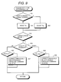
- FIG. 9 is a control flowchart for determining occurrence of a change with time.
- FIG. 1 is a system block diagram.
- an engine 101 is a four-cylinder engine in this embodiment.
- the engine 101 is equipped with an ignition device 102.
- the ignition device 102 has four ignition plugs 103 corresponding to the number of the cylinders of the engine 101.
- An intake pipe 104 for taking air into the engine 101 has an electronically controlled throttle 105 for regulating the air flowing therethrough, a fuel injection device 106 for injecting the fuel, and an air flow meter 107.
- the fuel injection device 106 has four fuel injection valves 108 corresponding to the number of the cylinders of the engine 101.
- the electronically controlled throttle 105 causes an actuator 109 to drive a throttle valve 110 for controlling the air flow.
- the throttle valve 110 is connected with an accelerator pedal (not shown) by a mechanical wire (not shown) so that the two members operate in an interlocked manner.
- a crank shaft 111 of the engine 101 is furnished with a flywheel 112.
- the flywheel 112 has an engine speed sensor 113 for detecting revolutions of the crank shaft 111, i.e., an engine speed Ne.
- a torque converter 114 directly coupled with the flywheel 112 comprises a pump 115, a turbine 116, and a stator 117.
- the output shaft of the turbine 116, i.e., a torque converter output shaft 118 is directly coupled with a stepped transmission mechanism 119.
- the torque converter output shaft 118 is equipped with a turbine speed sensor 120 for measuring a turbine speed Nt.
- the transmission mechanism 119 comprises a planetary gear 121 and friction engagement devices 122 and 123.
- the transmission mechanism 119 is coupled with a drive shaft 124.
- Vehicle or automatic transmission 130 is equipped with an acceleration sensor 125.
- the automatic transmission 130 is constituted of the aforesaid components. While the acceleration sensor 125 is used for detecting acceleration in the present embodiment, a drive shaft torque To may be detected, as an alternative, by the use of a torque sensor (not shown) attached to the drive shaft 124 of the transmission.
- Actuators for driving the above described engine 101 and the automatic transmission 130 are controlled by a controller 131.
- the controller 131 are supplied with such parameters as throttle valve opening ⁇ , transmission output shaft speed No, turbine speed Nt, engine speed Ne, transmission oil temperature Toil, and accelerator pedal angle ⁇ for use in the controlling.
- the acceleration sensor 125 since the acceleration is obtained from the differential signal of the transmission output shaft speed No, the acceleration sensor 125 may be superseded thereby.
- a torque sensor (not shown) may be attached to the drive shaft 124 of the transmission, and the drive shaft torque To of the transmission detected by the torque sensor may be supplied to the controller 131. Since the torque signal has a waveform similar to that of the signal from the acceleration sensor 125, the torque sensor may be used in place of the acceleration sensor 125.
- An engine torque control means 132 within the controller 131 outputs control signals to the electronically controlled throttle 105, fuel injection device 106, and the ignition device 102. These control signals are used for suppressing fluctuations in the torque at the time of shifting.
- FIG. 2 is a hardware block diagram of the controller 131 shown in FIG. 1.
- the controller comprises a filter 801 and a waveform shaping circuit 802 receiving signals from various sensors, a single chip microcomputer 803, and a drive circuit 804 for outputting drive control signals to various actuators such as valves.
- the microcomputer 803 includes a CPU 805 for performing various calculations, a ROM 806 for storing programs and data to be executed by the CPU 805, a RAM 807 for temporarily storing various data, a timer 808, an SCI (Serial Communication Interface) circuit 809, an I/O circuit 810, and an A/D converter 811. Namely, various functions of the controller 131 are carried out by the CPU 805 performing predetermined calculations based on the programs and data stored in the ROM 806 and RAM 807.
- controller 131 such as the single chip configuration, a configuration in which a plurality of single chip microcomputers communicate with each other through a dual-port RAM, and a configuration in which a plurality of single chip microcomputers communicate with each other through a LAN (Local Area Network) can be mentioned.
- LAN Local Area Network
- an inertia phase detection means 133 within the controller 131 performs digital processing and filtering processing of an acceleration signal (hereinafter called G signal) so that torque variation detection can be easily performed in a torque variation detection means 134.
- the torque variation detection means 134 detects the inertia phase in the shifting operation by using a filtering value Gf of the G signal.
- Gf acceleration signal
- a signal of the drive shaft torque To as differential of the drive shaft speed No may be used.
- the filtering processed signal Gf is further differentiated in a torque variation coefficient calculation means 135 and thereby the rate of variation of the acceleration is obtained. Since the rate of variation varies around the starting point of the inertia phase detected as described above due to a change with time occurring in the friction engagement devices, it becomes possible to determine the existence of a change with time in the friction engagement devices.
- a change-with-time determination means 136 there is stored a constant of reference level obtained through previously conducted experiments for determining the existence of a change with time. The constant is compared with the rate of torque variation obtained by the torque variation coefficient calculation means 135 in a comparison means 137 and, thereby, it is determined whether or not a change with time exists.
- a previously held hydraulic pressure command value (described later) for controlling the hydraulic pressure to be supplied to the friction engagement device on the disengaging side (here, the shifting is assumed to be 2-to-3 shifting) should be lowered so that the friction engagement device on the disengaging side 123 can easily disengage.
- a pressure control command generation means 138 outputs the pressure control command lowered as described above to the linear solenoid 128.
- FIG. 3 is a time chart of control to cope with a change with time carried out at the time of shifting up.
- the description here will be made taking a 2-to-3 shifting as an example.
- the signal Gf (hereinafter briefly referred to as Gf) obtained by subjecting the longitudinal vehicle acceleration signal to the filtering process is stored as a pre-shift acceleration signal Gs (hereinafter briefly referred to as Gs).
- Gs pre-shift acceleration signal
- Gshift a constant Gshift for varying the value Gf for detecting the start of the torque phase is set up.
- the value Gshift needs to be varied depending on the change in the throttle opening ⁇ (hereinafter briefly referred to as ⁇ ), namely the magnitude of the engine load.
- an engaging hydraulic pressure command value HC (hereinafter briefly referred to as HC) is raised and a disengaging hydraulic pressure command value BB (hereinafter briefly referred to as BB) is lowered.
- the lowered value should be such as to previously establish the value BB that brings the hydraulic pressure very close to the point of disengagement to thereby shorten the disengaging period of the engagement device on the disengaging side.
- the value is called here a previously held hydraulic pressure command value.
- the signal Gf sharply rises at the beginning of the inertia phase and, thereafter, it gently rises at a value determined by the hydraulic pressure supplied to the friction engagement device on the engaging side and the capacity of the engagement device.
- a change with time has occurred in the engagement device, such a phenomenon takes place in which the signal Gf gently rises at the beginning of the inertia phase and then sharply rises as indicated by the broken line. Therefore, by using the differential value dGf/dt of GF at the beginning of the inertia phase, the change with time of the engagement device can be detected. More particularly, when the value dGf/dt at the beginning of the inertia phase in FIG. 3 is found smaller than the previously stored reference level for determining existence of a change with time, it is determined that a change with time exists in the engagement device.
- FIG. 4 is a time chart of control to cope with a change with time carried out at the time of shifting down.
- the description here will be made taking 3-to-2 shifting as an example.
- the value Gf is stored as the value Gs.
- the value Gshift for detecting the stage prior to the start of the inertia phase is established.
- the value Gshift needs to be varied depending on the change of ⁇ , i.e., on the magnitude of the engine load.
- a disengaging hydraulic pressure command value HD hereinafter briefly referred to as HD
- the lowered value is previously obtained by matching.
- an engaging hydraulic pressure command value BC (hereinafter briefly referred to as BC) is raised.
- BC an engaging hydraulic pressure command value
- the raised value should be such as to previously establish the value BC that brings the hydraulic pressure very close to the point of engagement to thereby shorten the engaging period of the engagement device on the engaging side. This value also varies with Toil and ⁇ .
- the value Gf comes to agree with the value Gs plus Gshift and the value BC is raised stepwise to cause the engagement device on the engaging side to engage.
- an effective engaging hydraulic pressure BC can be brought virtually concurrent with the hollow circled point at the beginning of the inertia phase and a good shifting characteristic can be obtained.
- the value HD is kept constant during the period of the inertia phase so that the lowering rate of the value Gf after the inertia phase has started becomes small.
- the value Gf falls gently and then, after the torque phase has begun, it rises sharply and the shifting is ended.
- the change with time of the engagement device can be detected by using the differential value dGf/dt of the value Gf at the time when the inertia phase has occurred. More particularly, when the value dGf/dt at the beginning of the inertia phase shown in FIG. 4 is found smaller than the previously stored constant for determining existence of a change with time, it is determined that a change with time exists in the engagement device.
- FIG. 5 is a control flowchart of the above embodiment.
- step 401 it is determined by using the acceleration signal G whether or not the state of shifting at the moment is that of the beginning of an inertia phase. If the result is yes, the control advances to step 402, and therein the differential dGf (hereinafter briefly referred to as dGf) of the longitudinal vehicle acceleration is calculated. Then, in step 403, it is determined whether the shift command signal is for upshift or downshift. If the command signal is for upshift, the control advances to step 404. In step 404, it is determined whether the value dGf is smaller than a constant kup for determining existence of a change with time.
- step 405 correction is made so that the previously held hydraulic pressure command value of the disengaging hydraulic pressure command value BB is decreased and this corrected value is used at the shifting next time.
- step 406 it is determined whether the value dGf is smaller than a constant kdw for determining existence of a change with time. If the result is yes, it is determined that a change with time is existing and the control advances to step 407. In step 407, correction is made so that the previously held hydraulic pressure command value of the disengaging hydraulic pressure command value HD is decreased and this corrected value is used at the shifting next time.
- FIG. 6 to FIG. 9 show a second embodiment of the present invention.
- FIG. 6 is a system block diagram similar to FIG. 1, though illustrations of the engine 101 and the automatic transmission 130 are omitted.
- a torque phase detection means 502 within a controller 501 performs digital processing and filtering processing of the acceleration sensor 125 and detects the torque phase in a shifting operation by using the filtering value Gf.
- a shift command signal detection means 503 checks the shift command signal from the automatic transmission 130 and detects a shift pattern (for example, shifting up from second to third).
- a torque phase starting time calculation means 504 calculates the period of time from the time when a change in the shift command is detected in the shift command signal detection means to the time when it is detected in the torque phase detection means that the torque phase has started, i.e., a torque phase starting time Ttq (hereinafter referred to as Ttq). Since the detected torque phase starting time varies, or, more particularly, becomes longer, when a change with time has occurred in the friction engagement device on the engaging side, it becomes possible to determine that a change with time has occurred in the friction engagement device by using the value of the torque phase starting time.
- a change-with-time determination means 505 stores therein a constant of reference level obtained through previously conducted experiments for determining existence of a change with time. This constant is compared with the time obtained by the torque phase starting time calculation means 504 in a comparison means 506 for determining whether or not a change with time exists. If it is determined, in the case of upshift, in the comparison means 506 that a change with time exists, a previously held hydraulic pressure command value (described later) for controlling the hydraulic pressure to be supplied to the friction engagement device on the engaging side (here, it is assumed that 2-to-3 shifting is being carried out) should be raised so that the friction engagement device on the engaging side 123 can easily engage. Then, a controlling pressure generation means 507 outputs the raised controlling pressure command value to the linear solenoid 128.
- FIG. 7 is a time chart of control to cope with existence of a change with time of the friction engagement device on the engaging side carried out at the time of shifting up.
- description will be made taking a case of 2-to-3 shifting as an example.
- the value Gf is stored as a pre-shift acceleration signal Gs (hereinafter briefly referred to as Gs), a constant Gshift (hereinafter briefly referred to as Gshift) for varying the value Gf for detecting the start of the torque phase is established, and the values HC and BB are set to the previously held standby hydraulic pressure command values. The time at this point is set to 0. After the torque phase has started, the value Gf reaches the value Gs plus Gshift at the hollow circled point of the value Gf in the chart and the value BB for causing the friction engagement device on the disengaging side to disengage is lowered stepwise.
- Gs pre-shift acceleration signal
- Gshift a constant Gshift
- Ttq torque phase starting time
- FIG. 8 is a time chart of control to cope with existence of a change with time at the time of shifting down.
- the value Gf is stored as the value Gs before the shift command signal changes from third to second. Then, it is determined whether or not a shift command is generated. When it is generated, the value HD is lowered and the value BC is raised. The time at this point is set to 0.
- the value Gf comes to agree with the value GS plus Gshift at the hollow circled point in the chart of the value Gf and the value BC for causing the friction engagement device on the engagement side to engage is raised stepwise.
- the effective hydraulic pressure BC is brought virtually concurrent with the hollow circled point at the stage prior to the start of the inertia phase and a good shifting characteristic can be obtained.
- the value HD in the inertia phase is kept constant so that the rate of fall of the value Gf after the start of the inertia phase becomes smaller. After the start of the inertia phase, the value Gf gently falls until the torque phase is started.
- the differential dGf/dt (hereinafter briefly referred to as dGf/dt) of the longitudinal vehicle acceleration is inverted from a negative value to a positive value, whereby the starting time point of the torque phase is detected.
- the time at this point is stored as Tqf.
- FIG. 9 is a control flowchart of the second embodiment.
- step 801 it is determined whether or not the shift command signal has been changed.
- the control advances to step 802 and the torque phase starting time Ttq is reset and, when the result is no, the control advances to step 803 and the time Ttq is counted therein.
- step 804 it is determined whether the torque phase has started by using the value of the longitudinal vehicle acceleration.
- the control advances to step 805.
- step 805 it is determined whether the shift command signal is that for shifting up or shifting down. If the shift command signal is that for shifting up, the control advances to step 806.
- step 806 it is determined whether or not the time Ttq is greater than the reference level kup for determining existence of a change with time. When the result is yes, it is determined that a change with time exists and the control advances to step 807.
- step 807 correction is made to increase the previously held hydraulic pressure command value for the disengaging hydraulic pressure command value HC, and this corrected value is used at the time of shifting next time.
- step 805 if the command signal is that for shifting down, the control advances to step 808.
- step 808 it is determined whether or not the time Ttq is greater than the reference level kdw for determining occurrence of a change with time, and, when the result is yes, it is determined that a change with time exists and the control advances to step 809.
- step 809 correction is made so that the previously held hydraulic pressure command signal value for the disengaging hydraulic pressure command value BC is increased and this value is used in the 3-to-2 shifting next time.
- the present invention it is made possible to provide an apparatus for controlling transmission and method of controlling transmission whereby, even when a change with time has occurred in the friction engagement device of the automatic transmission, fluctuations in the torque are suppressed without the need for increasing the capacity of ROM in the microcomputer and comfortable acceleration feeling is continuously obtained.
Landscapes
- Engineering & Computer Science (AREA)
- General Engineering & Computer Science (AREA)
- Mechanical Engineering (AREA)
- Physics & Mathematics (AREA)
- Fluid Mechanics (AREA)
- Control Of Transmission Device (AREA)
- Electric Propulsion And Braking For Vehicles (AREA)
- Control Of Driving Devices And Active Controlling Of Vehicle (AREA)
Applications Claiming Priority (3)
| Application Number | Priority Date | Filing Date | Title |
|---|---|---|---|
| JP09797896A JP3746100B2 (ja) | 1996-04-19 | 1996-04-19 | 変速制御装置および制御方法 |
| JP97978/96 | 1996-04-19 | ||
| JP9797896 | 1996-04-19 |
Publications (3)
| Publication Number | Publication Date |
|---|---|
| EP0802354A2 true EP0802354A2 (de) | 1997-10-22 |
| EP0802354A3 EP0802354A3 (de) | 1999-03-03 |
| EP0802354B1 EP0802354B1 (de) | 2002-09-18 |
Family
ID=14206759
Family Applications (1)
| Application Number | Title | Priority Date | Filing Date |
|---|---|---|---|
| EP97106465A Expired - Lifetime EP0802354B1 (de) | 1996-04-19 | 1997-04-18 | Vorrichtung und Verfahren zur Steuerung eines Automatikgetriebes von einem Kraftfahrzeug |
Country Status (5)
| Country | Link |
|---|---|
| US (1) | US6094613A (de) |
| EP (1) | EP0802354B1 (de) |
| JP (1) | JP3746100B2 (de) |
| KR (1) | KR100491904B1 (de) |
| DE (1) | DE69715502T2 (de) |
Cited By (1)
| Publication number | Priority date | Publication date | Assignee | Title |
|---|---|---|---|---|
| WO2009095250A1 (de) * | 2008-02-01 | 2009-08-06 | Getrag Getriebe- Und Zahnradfabrik Hermann Hagenmeyer Gmbh & Cie Kg | Vorrichtung und verfahren zum verhindern von fehlschaltungen in automatischen getrieben von kraftfahrzeugen |
Families Citing this family (11)
| Publication number | Priority date | Publication date | Assignee | Title |
|---|---|---|---|---|
| JP2000161479A (ja) * | 1998-11-30 | 2000-06-16 | Aisin Seiki Co Ltd | 車両用自動変速機のクラッチツウクラッチ変速の際のトルク相開始の検出方法およびトルク干渉強さの検出方法、並びに車両用自動変速機の変速制御装置 |
| JP3699628B2 (ja) * | 2000-02-22 | 2005-09-28 | 株式会社日立製作所 | 自動変速機の制御装置 |
| JP3562425B2 (ja) * | 2000-03-07 | 2004-09-08 | 日産自動車株式会社 | 自動変速機のアップシフトショック軽減装置 |
| JP2002227989A (ja) * | 2001-01-29 | 2002-08-14 | Aisin Seiki Co Ltd | 自動変速機の油圧制御装置 |
| JP4062666B2 (ja) * | 2002-03-25 | 2008-03-19 | 本田技研工業株式会社 | トルク変動制御装置及びトルク変動制御プログラム |
| US7686214B1 (en) | 2003-05-12 | 2010-03-30 | Id Analytics, Inc. | System and method for identity-based fraud detection using a plurality of historical identity records |
| US10521857B1 (en) | 2003-05-12 | 2019-12-31 | Symantec Corporation | System and method for identity-based fraud detection |
| US20060149674A1 (en) * | 2004-12-30 | 2006-07-06 | Mike Cook | System and method for identity-based fraud detection for transactions using a plurality of historical identity records |
| JP2007198470A (ja) * | 2006-01-25 | 2007-08-09 | Jatco Ltd | 自動変速機の変速制御 |
| JP5018107B2 (ja) * | 2007-01-26 | 2012-09-05 | トヨタ自動車株式会社 | パワートレーンの制御装置、制御方法、その方法を実現させるプログラムおよびそのプログラムを記録した記録媒体 |
| JP5624352B2 (ja) * | 2010-04-19 | 2014-11-12 | 本田技研工業株式会社 | 自動変速機の制御装置 |
Family Cites Families (13)
| Publication number | Priority date | Publication date | Assignee | Title |
|---|---|---|---|---|
| JP2696819B2 (ja) * | 1986-10-08 | 1998-01-14 | 日産自動車株式会社 | 自動変速機の変速シヨツク軽減装置 |
| JPH02256959A (ja) * | 1989-03-28 | 1990-10-17 | Aisin Seiki Co Ltd | 電子制御自動変速装置 |
| JPH03219161A (ja) * | 1990-01-25 | 1991-09-26 | Japan Electron Control Syst Co Ltd | 自動変速機のライン圧学習制御装置 |
| JPH03292446A (ja) * | 1990-04-06 | 1991-12-24 | Japan Electron Control Syst Co Ltd | 自動変速機の変速作動油圧制御装置 |
| US5188005A (en) * | 1990-09-14 | 1993-02-23 | Ford Motor Company | Method and system for improving smoothness of shifts in an automatic transmission |
| JPH0587227A (ja) * | 1991-09-30 | 1993-04-06 | Mazda Motor Corp | 自動変速機の変速制御装置 |
| JPH05164236A (ja) * | 1991-12-06 | 1993-06-29 | Toyota Motor Corp | 自動変速機の変速制御装置 |
| JP2884906B2 (ja) * | 1992-04-16 | 1999-04-19 | 三菱自動車工業株式会社 | 車両用自動変速機の変速制御方法 |
| JP3260438B2 (ja) * | 1992-08-24 | 2002-02-25 | ジヤトコ・トランステクノロジー株式会社 | 自動変速機の制御装置 |
| KR100298250B1 (ko) * | 1992-09-16 | 2001-10-24 | 가나이 쓰도무 | 차량용구동력제어장치 |
| DE4237878C2 (de) * | 1992-11-10 | 2003-09-25 | Bosch Gmbh Robert | Verfahren zur Regelung des Schaltkomforts bei Fahrzeugen mit automatischem Getriebe |
| JP3508204B2 (ja) * | 1994-04-22 | 2004-03-22 | マツダ株式会社 | 自動変速機の変速ショック低減装置 |
| JP3427476B2 (ja) * | 1994-05-12 | 2003-07-14 | 株式会社デンソー | 車両用自動変速機における変速過渡制御方法 |
-
1996
- 1996-04-19 JP JP09797896A patent/JP3746100B2/ja not_active Expired - Fee Related
-
1997
- 1997-04-17 US US08/840,856 patent/US6094613A/en not_active Expired - Fee Related
- 1997-04-18 EP EP97106465A patent/EP0802354B1/de not_active Expired - Lifetime
- 1997-04-18 DE DE69715502T patent/DE69715502T2/de not_active Expired - Fee Related
- 1997-04-18 KR KR1019970014424A patent/KR100491904B1/ko not_active Expired - Fee Related
Cited By (3)
| Publication number | Priority date | Publication date | Assignee | Title |
|---|---|---|---|---|
| WO2009095250A1 (de) * | 2008-02-01 | 2009-08-06 | Getrag Getriebe- Und Zahnradfabrik Hermann Hagenmeyer Gmbh & Cie Kg | Vorrichtung und verfahren zum verhindern von fehlschaltungen in automatischen getrieben von kraftfahrzeugen |
| US8108113B2 (en) | 2008-02-01 | 2012-01-31 | Getrag Getriebe- Und Zahnradfabrik Hermann Hagenmeyer Gmbh & Cie Kg | Apparatus and method for preventing incorrect gear shifts in automatic transmissions of motor vehicles |
| CN101981354B (zh) * | 2008-02-01 | 2013-10-23 | 格特拉格传动机构和齿轮工厂赫尔曼·哈根迈尔有限公司&两合公司 | 用于防止在机动车的自动变速器中错误换挡的方法和装置 |
Also Published As
| Publication number | Publication date |
|---|---|
| DE69715502D1 (de) | 2002-10-24 |
| EP0802354B1 (de) | 2002-09-18 |
| DE69715502T2 (de) | 2003-05-22 |
| EP0802354A3 (de) | 1999-03-03 |
| US6094613A (en) | 2000-07-25 |
| JPH09280358A (ja) | 1997-10-28 |
| KR970070659A (ko) | 1997-11-07 |
| KR100491904B1 (ko) | 2005-09-28 |
| JP3746100B2 (ja) | 2006-02-15 |
Similar Documents
| Publication | Publication Date | Title |
|---|---|---|
| US5188005A (en) | Method and system for improving smoothness of shifts in an automatic transmission | |
| US5613920A (en) | Torque feedback shift control device and method | |
| US6243637B1 (en) | Control apparatus and method for automatic transmission by oil pressure on clutch | |
| EP0802354B1 (de) | Vorrichtung und Verfahren zur Steuerung eines Automatikgetriebes von einem Kraftfahrzeug | |
| US20050131612A1 (en) | Gear-shift control apparatus for automatic transmission and gear-shift control method | |
| US4807497A (en) | System for integrally controlling automatic transmission and engine | |
| EP0805060B1 (de) | Steuerungssystem für Brennkraftmaschinen für Kraftfahrzeuge | |
| KR20060052175A (ko) | 엔진 토크 제어 장치 | |
| US6328673B1 (en) | Control apparatus for an automatic transmission of a vehicle and a control method | |
| JP3317078B2 (ja) | 自動変速機の制御装置 | |
| US5816976A (en) | Driving torque control device and method for controlling driving torque | |
| US6471620B2 (en) | Control method for automatic transmission | |
| JPH09303542A (ja) | 自動変速機の制御装置及び制御方法 | |
| US6308128B1 (en) | Driving force control for automotive vehicle | |
| JP3009781B2 (ja) | 自動変速機の制御装置 | |
| JPH0467058B2 (de) | ||
| JPH10184871A (ja) | 自動変速機の制御装置および制御方法 | |
| US6450920B1 (en) | Method of controlling upshift for an automatic transmission | |
| JPH02197431A (ja) | 過給機付エンジンを備えた自動変速機の変速制御装置 | |
| JP3446494B2 (ja) | 変速制御装置及び変速制御方法 | |
| KR0168161B1 (ko) | 자동변속기의 변속 충격 경감장치 | |
| US7278952B2 (en) | Terminating or disallowing signals to increase a throttle opening | |
| JPH09125998A (ja) | 変速ショック低減装置 | |
| JPH08177541A (ja) | エンジントルク制御装置 | |
| JP2890925B2 (ja) | エンジン出力対応変速制御装置 |
Legal Events
| Date | Code | Title | Description |
|---|---|---|---|
| PUAI | Public reference made under article 153(3) epc to a published international application that has entered the european phase |
Free format text: ORIGINAL CODE: 0009012 |
|
| AK | Designated contracting states |
Kind code of ref document: A2 Designated state(s): DE GB |
|
| PUAL | Search report despatched |
Free format text: ORIGINAL CODE: 0009013 |
|
| AK | Designated contracting states |
Kind code of ref document: A3 Designated state(s): DE GB |
|
| 17P | Request for examination filed |
Effective date: 19990127 |
|
| 17Q | First examination report despatched |
Effective date: 20010112 |
|
| GRAG | Despatch of communication of intention to grant |
Free format text: ORIGINAL CODE: EPIDOS AGRA |
|
| GRAG | Despatch of communication of intention to grant |
Free format text: ORIGINAL CODE: EPIDOS AGRA |
|
| GRAH | Despatch of communication of intention to grant a patent |
Free format text: ORIGINAL CODE: EPIDOS IGRA |
|
| GRAH | Despatch of communication of intention to grant a patent |
Free format text: ORIGINAL CODE: EPIDOS IGRA |
|
| GRAA | (expected) grant |
Free format text: ORIGINAL CODE: 0009210 |
|
| AK | Designated contracting states |
Kind code of ref document: B1 Designated state(s): DE GB |
|
| REG | Reference to a national code |
Ref country code: GB Ref legal event code: FG4D |
|
| REF | Corresponds to: |
Ref document number: 69715502 Country of ref document: DE Date of ref document: 20021024 |
|
| PLBE | No opposition filed within time limit |
Free format text: ORIGINAL CODE: 0009261 |
|
| STAA | Information on the status of an ep patent application or granted ep patent |
Free format text: STATUS: NO OPPOSITION FILED WITHIN TIME LIMIT |
|
| 26N | No opposition filed |
Effective date: 20030619 |
|
| PGFP | Annual fee paid to national office [announced via postgrant information from national office to epo] |
Ref country code: GB Payment date: 20080328 Year of fee payment: 12 |
|
| PGFP | Annual fee paid to national office [announced via postgrant information from national office to epo] |
Ref country code: DE Payment date: 20080606 Year of fee payment: 12 |
|
| GBPC | Gb: european patent ceased through non-payment of renewal fee |
Effective date: 20090418 |
|
| PG25 | Lapsed in a contracting state [announced via postgrant information from national office to epo] |
Ref country code: DE Free format text: LAPSE BECAUSE OF NON-PAYMENT OF DUE FEES Effective date: 20091103 |
|
| PG25 | Lapsed in a contracting state [announced via postgrant information from national office to epo] |
Ref country code: GB Free format text: LAPSE BECAUSE OF NON-PAYMENT OF DUE FEES Effective date: 20090418 |