EP0818318B1 - Méthode pour la correction de densités irrégulières dans l'enregistrement thermique - Google Patents
Méthode pour la correction de densités irrégulières dans l'enregistrement thermique Download PDFInfo
- Publication number
- EP0818318B1 EP0818318B1 EP97111480A EP97111480A EP0818318B1 EP 0818318 B1 EP0818318 B1 EP 0818318B1 EP 97111480 A EP97111480 A EP 97111480A EP 97111480 A EP97111480 A EP 97111480A EP 0818318 B1 EP0818318 B1 EP 0818318B1
- Authority
- EP
- European Patent Office
- Prior art keywords
- thermal
- image data
- line
- deformation
- recording
- Prior art date
- Legal status (The legal status is an assumption and is not a legal conclusion. Google has not performed a legal analysis and makes no representation as to the accuracy of the status listed.)
- Expired - Lifetime
Links
- 238000000034 method Methods 0.000 title claims description 29
- 239000000463 material Substances 0.000 claims description 57
- 230000008859 change Effects 0.000 claims description 30
- 238000012937 correction Methods 0.000 claims description 25
- 238000007620 mathematical function Methods 0.000 claims description 17
- 238000012886 linear function Methods 0.000 claims description 4
- 230000032258 transport Effects 0.000 description 82
- 230000006870 function Effects 0.000 description 13
- 238000012545 processing Methods 0.000 description 10
- 230000001105 regulatory effect Effects 0.000 description 8
- 230000007704 transition Effects 0.000 description 8
- 238000013500 data storage Methods 0.000 description 7
- 238000010586 diagram Methods 0.000 description 5
- 230000004044 response Effects 0.000 description 5
- 239000003086 colorant Substances 0.000 description 4
- 230000007246 mechanism Effects 0.000 description 4
- 230000008901 benefit Effects 0.000 description 3
- 238000004140 cleaning Methods 0.000 description 3
- 238000003745 diagnosis Methods 0.000 description 3
- 230000014509 gene expression Effects 0.000 description 3
- 230000002123 temporal effect Effects 0.000 description 3
- 238000004364 calculation method Methods 0.000 description 2
- 239000000470 constituent Substances 0.000 description 2
- 230000007423 decrease Effects 0.000 description 2
- 230000020169 heat generation Effects 0.000 description 2
- 230000004048 modification Effects 0.000 description 2
- 238000012986 modification Methods 0.000 description 2
- 229920000139 polyethylene terephthalate Polymers 0.000 description 2
- 239000005020 polyethylene terephthalate Substances 0.000 description 2
- 238000001454 recorded image Methods 0.000 description 2
- 239000000758 substrate Substances 0.000 description 2
- 238000012546 transfer Methods 0.000 description 2
- 238000001816 cooling Methods 0.000 description 1
- 230000001186 cumulative effect Effects 0.000 description 1
- 230000007547 defect Effects 0.000 description 1
- 230000003111 delayed effect Effects 0.000 description 1
- 230000000881 depressing effect Effects 0.000 description 1
- 230000000994 depressogenic effect Effects 0.000 description 1
- 238000013461 design Methods 0.000 description 1
- 230000006866 deterioration Effects 0.000 description 1
- 230000000694 effects Effects 0.000 description 1
- 230000002708 enhancing effect Effects 0.000 description 1
- 238000001914 filtration Methods 0.000 description 1
- 230000006872 improvement Effects 0.000 description 1
- 239000002184 metal Substances 0.000 description 1
- -1 polyethylene terephthalate Polymers 0.000 description 1
- 230000009467 reduction Effects 0.000 description 1
- 238000012552 review Methods 0.000 description 1
Images


Classifications
-
- B—PERFORMING OPERATIONS; TRANSPORTING
- B41—PRINTING; LINING MACHINES; TYPEWRITERS; STAMPS
- B41J—TYPEWRITERS; SELECTIVE PRINTING MECHANISMS, i.e. MECHANISMS PRINTING OTHERWISE THAN FROM A FORME; CORRECTION OF TYPOGRAPHICAL ERRORS
- B41J25/00—Actions or mechanisms not otherwise provided for
- B41J25/304—Bodily-movable mechanisms for print heads or carriages movable towards or from paper surface
- B41J25/312—Bodily-movable mechanisms for print heads or carriages movable towards or from paper surface with print pressure adjustment mechanisms, e.g. pressure-on-the paper mechanisms
-
- B—PERFORMING OPERATIONS; TRANSPORTING
- B41—PRINTING; LINING MACHINES; TYPEWRITERS; STAMPS
- B41J—TYPEWRITERS; SELECTIVE PRINTING MECHANISMS, i.e. MECHANISMS PRINTING OTHERWISE THAN FROM A FORME; CORRECTION OF TYPOGRAPHICAL ERRORS
- B41J2/00—Typewriters or selective printing mechanisms characterised by the printing or marking process for which they are designed
- B41J2/315—Typewriters or selective printing mechanisms characterised by the printing or marking process for which they are designed characterised by selective application of heat to a heat sensitive printing or impression-transfer material
- B41J2/32—Typewriters or selective printing mechanisms characterised by the printing or marking process for which they are designed characterised by selective application of heat to a heat sensitive printing or impression-transfer material using thermal heads
Definitions
- This invention relates to a method of correcting uneven densities that occur in the image being recorded on a thermal recording material (hereunder referred to as a "thermal material”) with a thermal recording apparatus in association with image data.
- a thermal recording material hereunder referred to as a "thermal material”
- Thermal materials such as thermal films comprising a thermal recording layer on a film substrate are commonly used to record images produced in diagnosis by ultrasonic scanning. This recording method eliminates the need for wet processing and offers several advantages including convenience in handling. Hence in recent years, the use of the thermal recording system is not limited to small-scale applications such as diagnosis by ultrasonic scanning and an extension to those areas of medical diagnoses such as CT, MRI and X-ray photography where large and high-quality images are required is under review.
- the thermal recording apparatus uses a thermal head having a glaze in which heat generating resistors corresponding to the number of pixels in one line are arranged in one direction and, with the glaze a little pressed against the thermal recording layer of the thermal material, the thermal material is transported for example by transport means such as a transport roller to be relatively moved in a direction approximately perpendicular to the direction in which the heat generating resistors are arranged, and the respective heat generating resistors of the glaze are heated in accordance with the image data to be recorded to heat the thermal recording layer of the thermal material, thereby accomplishing image reproduction.
- transport means such as a transport roller to be relatively moved in a direction approximately perpendicular to the direction in which the heat generating resistors are arranged
- the respective heat generating resistors of the glaze are heated in accordance with the image data to be recorded to heat the thermal recording layer of the thermal material, thereby accomplishing image reproduction.
- Such an apparatus is e.g. known from US-A-4 879566.
- the force of friction at the interface between the running thermal material and the thermal head changes in accordance with the density of the image being recorded on the thermal material. For example, depending on its characteristics, the thermal material is insufficiently melted on the surface during low-density recording that its surface is not in a highly slippery condition. On the other hand, during high-density recording, the surface of the thermal material is sufficiently melted to become highly slippery.
- Fig. 9 shows conceptually an example of the image being recorded.
- the image being recorded consists of a rectangular high-density area in the center of the thermal material and the surrounding low-density area. If the thermal material is transported in the direction of an arrow, the low-density area in the lower part of Fig. 9 is first recorded, then the central high-density area is recorded and finally the low-density area in the upper part is recorded.
- the transport rollers, or rollers for transporting the thermal material are controlled by a transport motor such that the thermal material is transported at a constant speed at all times; however, as already mentioned, the force of friction between the thermal material and the thermal head will vary with the recording density, causing a change in the torque of the transport motor that is required to transport the thermal material.
- a comparatively large transport torque is required when the surface of the thermal material is less slippery but a comparatively small transport torque will suffice if the surface of the thermal material is slippery.
- the transport rollers on the thermal recording apparatus are usually made of rubber and the shape of rubber rollers is deformed in response to the change in the transport torque. Briefly, the greater the transport torque, the more deformed the rubber rollers will be. Hence, the rubber rollers are deformed abruptly when recording is done at the transition from the area of small transport torque to the area of large torque; conversely, the rubber rollers will revert to the initial shape abruptly when recording is done at the transition from the area of large transport torque to the area of small torque.
- Rubber rollers are used as the transport rollers in order to ensure that the thermal material being transported is depressed sufficiently uniformly to improve the precision in its transport, thereby producing a recorded image of high quality.
- Non-rubber rollers such as metal rollers are incapable of depressing the thermal material uniformly in the presence of slight distortions, hence failing to transport the thermal material in high precision.
- the use of rubber rollers has a limitation in that no matter how much improved the transport motor is in terms of performance, the image being recorded will experience the aforementioned unevenness in density.
- the prior art thermal recording apparatus has had the problem that depending on the constituent material of the means for transporting the thermal material, uneven densities occur at density changing boundaries in response to the change in transport torque on account of the variation in recording density.
- the present invention has been accomplished under these circumstances and has as an object providing a method of correcting uneven densities in thermal recording apparatus by ensuring that no uneven densities due to the variation in recording density will occur at boundaries where the recording density makes a transition from low to high value and vice versa.
- the invention provides a method of correcting uneven densities in a thermal recording apparatus with which an image corresponding to image data is formed on a thermal recording material using a thermal head, wherein on the basis of a preliminarily computed mathematical function that represents the relationship between said image data and the frictional force between said thermal recording material and said thermal head, a total sum of functional values corresponding to the image data of individual pixels in a present line, as well as a total sum of functional values corresponding to the image data of individual pixels in a preceding line are taken and wherein said image data are corrected in accordance with the difference between said two total sums.
- said mathematical function representing the relationship between said image data and the frictional force between said thermal recording material and said thermal head is approximated by a linear function and that a total sum of image data values corresponding to said image data is taken in place of said functional values corresponding to said image data.
- the invention also provides a method of correcting uneven densities in a thermal recording apparatus with which an image corresponding to image data is formed on a thermal recording material using a thermal head, wherein on the basis of a preliminarily computed mathematical function that represents the relationship between said image data and the frictional force between said thermal recording material and said thermal head and also on the basis of another preliminarily computed mathematical function that represents the relationship between said frictional force and the amount of deformation of rubber rollers between which said thermal recording material is held for transport, an amount of change in the rubber roller's deformation is determined for the position of each pixel in each line and said image data for a present line are corrected in accordance with the amount of change in said rubber roller's deformation for the position of each pixel in the present line and the correction coefficient for a preceding line.
- the amount of change in said rubber roller's deformation for the position of each pixel in the present line is replaced by the sum of the mean average of changes in the amount of roller deformation for each line and the mean average of changes in the amount of roller deformation for a total of m pixels including a pixel of interest, as determined for the position of each pixel in each line.
- Fig. 1 shows schematically an embodiment of the thermal recording apparatus to which the method of correcting uneven densities of the invention is applied.
- the thermal recording apparatus generally indicated by 10 in Fig. 1 and which is hereunder simply referred to as a "recording apparatus 10" performs thermal recording on thermal films of a given size, say, B4 (namely, thermal films in the form of cut sheets).
- the apparatus comprises a loading section 14 where a magazine 24 containing thermal films A is loaded, a feed/transport section 16, a recording section 20 performing thermal recording on thermal films A by means of the thermal head 66, and an ejecting section 22.
- the thermal films A comprise respectively a substrate consisting of a transparent film such as a transparent polyethylene terephthalate (PET) film, which is overlaid with a thermal recording layer.
- a transparent film such as a transparent polyethylene terephthalate (PET) film
- PET polyethylene terephthalate
- thermal films A are stacked in a specified number, say, 100 to form a bundle, which is either wrapped in a bag or bound with a band to provide a package.
- the specified number of thermal films A bundled together with the thermal recording layer side facing down are accommodated in the magazine 24 of the recording apparatus 10, and they are taken out of the magazine 24 one by one to be used for thermal recording.
- the loading section 14 has an inlet 30 formed in the housing 28 of the recording apparatus 10, a guide plate 32, guide rolls 34 and a stop member 36.
- the magazine 24 is a case having a cover 26 which can be freely opened, and is inserted into the recording apparatus 10 via the inlet 30 of the loading section 14 in such a way that the portion fitted with the cover 26 is coming first; thereafter, the magazine 24 as it is guided by the guide plate 32 and the guide rolls 34 is pushed until it contacts the stop member 36, whereupon it is loaded at a specified position in the recording apparatus 10.
- the feed/transport section 16 has the sheet feeding mechanism using the sucker 40 for grabbing the thermal film A by application of suction, transport means 42, a transport guide 44 and a regulating roller pair 52 located in the outlet of the transport guide 44; the thermal films A are taken out of the magazine 24 in the loading section 14 and transported to the recording section 20.
- the transport means 42 is composed of a transport roller 46, a pulley 47a coaxial with the transport roller 46, a pulley 47b coupled to a rotating drive source, a tension pulley 47c, an endless belt 48 stretched between the three pulleys 47a, 47b and 47c, and a nip roller 50 that is to be pressed onto the transport roller 46.
- the cover 26 is opened by the OPEN/CLOSE mechanism (not shown) in the recording apparatus 10. Then, the sheet feeding mechanism using the sucker 40 picks up one sheet of thermal film A from the magazine 24 and feeds the forward end of the sheet to the transport means 42 (to the nip between rollers 46 and 50).
- the sucker 40 releases the film, and the thus fed thermal film A is supplied along the transport guide 44.
- the OPEN/CLOSE mechanism closes the cover 26.
- the distance between the transport means 42 and the regulating roller pair 52 which is defined by the transport guide 44 is set to be somewhat shorter than the length of the thermal film A in the direction of its transport.
- the advancing end of the thermal film A first reaches the regulating roller pair 52 by the transport means 42.
- the regulating roller pair 52 are normally at rest. The advancing end of the thermal film A stops here.
- the temperature of the thermal head 66 is checked and if it is at a specified level, the regulating roller pair 52 start to transport the thermal film A, which is transported to the recording section 20.
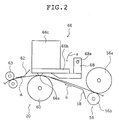
- Fig. 2 shows schematically the recording section 20.
- the recording section 20 has the thermal head 66, a platen roller 60, a cleaning roller pair 56, a guide 58, a fan 76 for cooling the thermal head 66 (see Fig. 1, not shown in Fig. 2), a guide 62, and a transport roller pair 63.
- the thermal head 66 is capable of thermal recording at a recording (pixel) density of, say, about 300 dpi on thermal films for example up to a maximum of B4 size.
- the head comprises a thermal head body 66b having a glaze 66a in which the heat generating resistors performing one line thermal recording on the thermal film A are arranged in one direction (perpendicular to the paper of Fig. 2), and a heat sink 66c fixed to the thermal head body 66b.
- the thermal head 66 is supported on a support member 68 that can pivot about a fulcrum 68a either in the direction of arrow a or in the reverse direction.
- the platen roller 60 rotates at a specified image recording speed while holding the thermal film A in a specified position, and transports the thermal film A in the direction (direction of arrow b in Fig. 2) approximately perpendicular to the direction in which the glaze 66a extends.
- the cleaning roller pair 56 comprises a sticky rubber roller 56a and a non-sticky roller 56b.
- the support member 68 Before the thermal film A is transported to the recording section 20, the support member 68 has pivoted to UP position (in the direction opposite to the direction of arrow a ) so that the glaze 66a of the thermal head 66 is not in contact with the platen roller 60.
- the support member 68 pivots in the direction of arrow a and the thermal film A becomes pinched between the glaze 66a on the thermal head 66 and the platen roller 60 such that the glaze 66a is pressed onto the recording layer while the thermal film A is transported in the direction of arrow b by means of the platen roller 60, the regulating roller pair 52 and the transport roller pair 63 as it is held in a specified position by the platen roller 60.
- the individual heat generating resistors on the glaze 66a are actuated in accordance with the data of the image to be recorded to perform imagewise thermal recording on the thermal film A.
- this operation of thermal recording in accordance with the data of the image to be recorded is performed by an image data processing system, which is described specifically below.
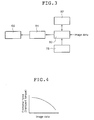
- Fig. 3 is a diagram showing the concept of an embodiment of the image data processing system.
- the illustrated system comprises a correction data storage unit 78 for holding various kinds of image data correcting data, an image processing unit 80 which performs various corrections (image processing) on the image data, an image memory 82 for holding the corrected image data, and a recording control unit 84 which controls the thermal head 66 on the basis of the image data held in the image memory 82.
- correction data storage unit 78 holds various kinds of image data associated correction data, one of which is the data for correcting the uneven densities that occur at density changing boundaries in response to the change in transport torque on account of the variation in recording density (such uneven densities are hereunder referred to as "uneven densities or density unevenness due to the variation in recording density”); in a specific case, a computing equation, a lookup table or the like is stored as a mathematical function that represents the relationship between the image data and the force of friction between the thermal film A and the thermal head 66.
- the data for correcting the uneven densities due to the variation in recording density namely, a mathematical function that represents the relationship between the image data and the force of friction between the thermal film A and the thermal head 66 can typically be computed preliminarily by outputting a pattern of image data in which the recording density increases progressively and measuring the transport torque in the transport motor by a suitable means such as a torque meter.
- the force of friction between the thermal film A and the thermal head 66 may typically be represented by the transport torque of the transport motor for driving the transport rollers.
- Fig. 4 is a graph showing an example of the data for correcting the uneven densities due to the variation in recording density.
- the horizontal axis of the graph plots the image data for the range of recording densities which are employed by the thermal recording apparatus 10, and the vertical axis plots the transport torque, or the image data associated force of friction between the thermal film A and the thermal head 66.
- the density of the image data increases toward the right end of the graph and decreases toward the left end; the higher the density of the image data, the more slippery is the surface of the thermal film A (i.e., the smaller the transport torque).
- Fig. 4 shows the case where the data for correcting the density unevenness due to the variation in recording density are represented graphically as a function; however, this is not the sole case of implementing the method of the invention for correcting uneven densities in thermal recording apparatus and other expressions may of course be adopted, such as a functional formula which is a mathematical expression of the relationship between the image data and the force of friction between the thermal film A and the thermal head 66, and a lookup table which is a numerical expression of the same relationship.
- the image processing unit 80 is supplied with image data from an image supply source such as CT or MRI, and the density unevenness due to the variation in recording density is corrected on the basis of the function, such as the following computing equation, that is stored in the correction data storage unit 78:
- n is a line number with the image to be recorded
- i is a pixel number for the nth line
- D'n(i) is the corrected image data value for the ith pixel at the nth line
- Dn(i) is the yet to be corrected image data value for the ith pixel at the nth line
- k is a correction coefficient
- Hn is a quantitative measure of the change in the force of friction between the thermal film A and the thermal head 66 at the nth line
- M is the total number of pixels in one line
- f(D) is a functional formula representing the relationship between the image data value D and the force of friction between the thermal film A and the thermal head 66.
- the total sum of the frictional forces (transport torques) associated with the individual pixels on the present line is subtracted from the total sum of the frictional forces (transport torques) associated with the individual pixels on the preceding line on the basis of the function stored in the correction data storage unit 78 to thereby compute the amount of the change that occurred in frictional force between the preceding and the present line; then, the calculated change is multiplied by the correction coefficient such that the unevenness in the density of the image being recorded due to the variation in recording density is corrected for each of the pixels on each line.
- the change in frictional force between the present and the preceding line namely, the change in transport torque that occurs as the result of the shift from the preceding line to the present line
- each of the pixels in each line is corrected on the basis of the calculated amount of the change in transport torque, whereby the uneven densities that occur in the image being recorded on account of the variation in recording density can be compensated appropriately to accomplish highly precise image recording.
- Fig. 5 is a graph showing another example of the data for correcting the uneven densities due to the variation in recording density.
- the difference from the graph shown in Fig. 4 is that the relationship between the image data and the force of friction between the thermal material and the thermal head can be approximated by a linear function.
- the horizontal axis of the graph plots the image data for the range of recording densities which are employed by the thermal recording apparatus 10, and the vertical axis plots the image data associated force of friction between the thermal film A and the thermal head.
- the image processing unit 80 performs various other kinds of image processing such as sharpness correction for enhancing the edge of the image, tone compensation for effecting correction in accordance with the tonal characteristics of the thermal film A, temperature compensation for adjusting the energy of heat generation in accordance with the temperature of heat generating resistors, resistance correction for correcting the difference between the resistances of adjacent heat generating resistors, black ratio compensation for correcting the unevenness in the image data of the same recording density that occurs due to the black ratio, and shading compensation for correcting the unevenness in recording density due to the thermal head 66; the corrected image data are then stored in the image memory 82.
- sharpness correction for enhancing the edge of the image
- tone compensation for effecting correction in accordance with the tonal characteristics of the thermal film A
- temperature compensation for adjusting the energy of heat generation in accordance with the temperature of heat generating resistors
- resistance correction for correcting the difference between the resistances of adjacent heat generating resistors
- black ratio compensation for correcting the unevenness in the image data of the same recording density that
- the recording control unit 84 controls the heat generation of the individual heat generating resistors that compose the glaze on the thermal head 66 and which have one-to-one correspondence to the respective pixels of one line and, as a result, a desired image is recorded.
- the thermal film A as it is guided by the guide 62 is transported by the platen roller 60 and the transport roller pair 63 to be ejected into a tray 72 in the ejecting section 22.
- the tray 72 projects exterior to the recording apparatus 10 via the outlet 74 formed in the housing 28 and the thermal film A carrying the recorded image is ejected via the outlet 74 for takeout by the operator.
- the recording apparatus 10 is basically as described above.
- the deformation of the rubber rollers is proportional to the force of friction between the thermal film A and the thermal head; the deformation is similar for all of the rubber rollers that are employed; and the change in the deformation of the rubber rollers ends within the one-line recording time in which the transport torque changed and no more effects are caused by the change to affect the recording density in subsequent lines. It is on the basis of these assumptions that the density unevenness which occurs in the image being recorded on account of the variation in recording density is effectively corrected for each of the pixels on each line in the image.
- Fig. 6 is a graph showing another example of the data for correcting the uneven densities due to the variation in recording density.
- the graph shows the force of friction between the thermal film A and the thermal head as it relates to the amount of deformation of rubber rollers.
- the horizontal axis of the graph plots the transport torque, or the force of friction between the thermal film A and the thermal head 66, and the vertical axis plots the deformation of rubber rollers as a function of the transport torque.
- the amount of deformation of rubber rollers is variable with their constituent material, the magnitude of transport torque, etc. and may be approximated by an exponential function of (transport torque) P .
- the possibility for the case where the force of friction between the thermal film A and the thermal head is not proportional to the amount of rubber roller's deformation is also taken into account and a mathematical function representing the relationship between transport torque and the amount of roller deformation is calculated preliminarily and stored in the correction data storage unit 78 in a suitable form such as a computing equation or a lookup table; on the basis of the stored function, the amount of roller deformation associated with the transport torque is computed by substituting Hn in Eq. (1) into the computing equation set forth below, whereby the correct amount of roller deformation can be calculated in association with the magnitude of transport torque:
- Fig. 7a is a graph showing the concept of an exemplary image being formed
- Fig. 7b is a graph showing the corresponding change in transport torque
- Fig. 7c is a graph showing the corresponding amount of deformation of rubber transport rollers.
- the image being recorded as shown in Fig. 7a is identical to the image shown in Fig. 9.
- Fig. 7b shows the amount by which the transport torque changes in the positions of the individual pixels in the main scanning direction when regions A and B of the image shown in Fig. 7a are being formed
- Fig. 7c shows the amount by which the rubber rollers deform in the positions of the individual pixels in the main scanning direction when the two regions are being formed.
- the high-density portion of region A corresponds to the area where the temperature of the thermal head is sufficiently high that the surface of the thermal material is comparatively melted to become fairly slippery.
- the force of friction between the thermal film A and the thermal head is small and so is the transport torque.
- the force of friction between the thermal film A and the thermal head is increased and so is the transport torque.
- the amount of rubber roller's deformation that occurs in response to the change in transport torque for each of the pixel positions on each line in the image being recorded as shown in Fig. 7a can be computed for the position of each of the pixels on each line.
- the propagation of the deformation to the surrounding pixels is calculated as shown in Fig. 7c and this can be accomplished by filtering, or a technique that represents a transfer function of deformation.
- the transfer of the deformation covers the entire length of the thermal head, so the filter length requires the total number of pixels, M, whereby a huge amount of calculations is necessary to determine the propagation of the deformation to the surrounding pixels.
- Fig. 7c can be approximated by the addition of the mean average for the overall length of the graph in Fig. 7b to the mean average of deformations over short distances, and the unevenness in density that occurs in the image being recorded on account of the variation in recording density may be effectively corrected for each of the pixels on each line in accordance with the following procedure.
- M represents the total number of pixels in one line:
- m/2 250 pixels being distributed both before and after the pixel position of interest:
- the mean average ( d n ) of the changes in the amount of rubber roller's deformation is determined for each line and, in addition, the mean average (d nm (i)) of the changes in the amount of roller deformation for a total of m pixels, with m/2 pixels being distributed both before and after the pixel of interest, is determined for each of the pixels in each line; thereafter, the two values of mean average are summed.
- the invention offers the advantage of ensuring that the uneven densities which occur in the image being recorded on account of the variation in recording density can be corrected more precisely for each of the pixels in each line.
- the mean average (d nm (i)) of the changes in the amount of roller deformation for a total of m pixels, with m/2 pixels being distributed both before and after the pixel of interest, is determined for each of the pixels in each line, and the value of m may be determined as appropriate for a selected factor such as the characteristics of the rubber rollers. If the value of m is increased, one can construct a smooth curve of the profile shown in Fig. 7c for the amount of rubber roller's deformation; on the other hand, a huge amount of calculations are obviously required to determine d nm (i). Therefore, the exact value of m is preferably determined in consideration of the desired precision in computing the amount of roller deformation and the time required to do it.
- Fig. 8 is a graph showing how the deformation of rubber rollers changes at the boundary between regions A and B of the image being recorded as shown in Fig. 7a. Obviously, the change in the deformation of rubber rollers is not momentary but delayed in time and it sometimes occurs that the recording density is affected until two or three lines after the transport torque changed.
- the method of the invention may employ the computing equation set forth below in order to compute a correction coefficient d' n (i) for each of the pixel positions in each line, thereby correcting the density unevenness in the image being recorded on account of the variation in recording density:
- D' n (i) (1+k ⁇ d' n (i)) ⁇ D n (i)
- d' n (i) k ⁇ ⁇ d' n-1 (i)+k ⁇ ⁇ d i + d nm (i)
- D' n (i) is the corrected image data value for the ith pixel at the nth line
- D n (i) is the yet to be corrected image data value for the ith pixel at the nth line
- d' n-1 (i) is a correction coefficient for each pixel at the preceding line
- k ⁇ and k ⁇ are constants.
- the method of the invention for correcting uneven densities in a thermal recording apparatus is capable of correcting the density unevenness due to the variation in recording density by taking into account the force of friction between the thermal film A and the thermal head as it relates to the amount of rubber roller's deformation, as well as the deformation of such rubber rollers for the position of each of the pixels in each line, and also the temporal effect of the change in that deformation; as a result, the method provides for the recording of high-quality images with minimal unevenness in density.
- the method of the invention for correcting density unevenness in a thermal recording apparatus computes the amount of a change in the force of friction between a thermal material and the thermal head for each line on the basis of a preliminarily calculated mathematical function which represents the relationship between the image data and the frictional force, and the image data for the present line are corrected in accordance with the difference between the changes in the frictional force for the preceding and the present line.
- the invention method may also be based on a mathematical function which represents the relationship between said frictional force and the deformation of rubber rollers such as to determine the amount of a change in the roller deformation for the position of each of the pixels in each line and the image data for the present line are corrected in accordance with the amount of the change in roller deformation for the position of each of the pixels in the present line and the correction coefficient for the preceding line.
- a mathematical function which represents the relationship between said frictional force and the deformation of rubber rollers such as to determine the amount of a change in the roller deformation for the position of each of the pixels in each line and the image data for the present line are corrected in accordance with the amount of the change in roller deformation for the position of each of the pixels in the present line and the correction coefficient for the preceding line.
Landscapes
- Electronic Switches (AREA)
Claims (4)
- Procédé de correction des densités irrégulières dans un appareil d'enregistrement thermique avec lequel une image correspondant à des données d'image est formée sur un matériau d'enregistrement thermique en utilisant une tête thermique, dans lequel une somme totale des valeurs fonctionnelles correspondant aux données d'image des pixels individuels dans une ligne précédente, ainsi qu'une somme totale des valeurs fonctionnelles correspondant aux données d'image des pixels individuels dans une ligne actuelle sont prises, et dans lequel lesdites données d'image de ladite ligne actuelle sont corrigées sur la base d'une fonction mathématique calculée au préalable qui représente la relation entre lesdites données d'image et la force de frottement entre ledit matériau d'enregistrement thermique et ladite tête thermique en fonction de la différence entre lesdites deux sommes totales.
- Procédé selon la revendication 1, dans lequel ladite fonction mathématique représentant la relation entre lesdites données d'image et la force de frottement entre ledit matériau d'enregistrement thermique et ladite tête thermique est approchée par une fonction linéaire, et dans lequel une somme totale des valeurs de données d'image correspondant auxdites données d'image est prise au lieu desdites valeurs fonctionnelles correspondant auxdites données d'image.
- Procédé de correction des densités irrégulières dans un appareil d'enregistrement thermique avec lequel une image correspondant à des données d'image est formée sur un matériau d'enregistrement thermique en utilisant une tête thermique, dans lequel, sur la base d'une fonction mathématique calculée au préalable qui représente la relation entre lesdites données d'image et la force de frottement entre ledit matériau d'enregistrement thermique et ladite tête thermique et, également, sur la base d'une autre fonction mathématique calculée au préalable qui représente la relation entre ladite force de frottement et la quantité de déformation des cylindres en caoutchouc entre lesquels ledit matériau d'enregistrement thermique est maintenu pour le transport, une quantité de variation de la déformation du cylindre en caoutchouc est déterminée pour la position de chaque pixel dans chaque ligne et lesdites données d'image pour une ligne actuelle sont corrigées en fonction de la quantité de variation de ladite déformation du cylindre en caoutchouc pour la position de chaque pixel dans la ligne actuelle et du coefficient de correction pour une ligne précédente.
- Procédé selon la revendication 3, dans lequel la quantité de variation de ladite déformation du cylindre en caoutchouc pour la position de chaque pixel dans la ligne actuelle est remplacée par la somme de la moyenne des variations de la quantité de déformation des cylindres pour chaque ligne et de la moyenne des variations de la quantité de déformation des cylindres pour un total de m pixels comprenant un pixel présentant un intérêt, telle que déterminée pour la position de chaque pixel dans chaque ligne.
Applications Claiming Priority (3)
| Application Number | Priority Date | Filing Date | Title |
|---|---|---|---|
| JP178129/96 | 1996-07-08 | ||
| JP17812996 | 1996-07-08 | ||
| JP17812996 | 1996-07-08 |
Publications (3)
| Publication Number | Publication Date |
|---|---|
| EP0818318A2 EP0818318A2 (fr) | 1998-01-14 |
| EP0818318A3 EP0818318A3 (fr) | 1998-01-28 |
| EP0818318B1 true EP0818318B1 (fr) | 2000-05-24 |
Family
ID=16043165
Family Applications (1)
| Application Number | Title | Priority Date | Filing Date |
|---|---|---|---|
| EP97111480A Expired - Lifetime EP0818318B1 (fr) | 1996-07-08 | 1997-07-07 | Méthode pour la correction de densités irrégulières dans l'enregistrement thermique |
Country Status (3)
| Country | Link |
|---|---|
| US (1) | US6091436A (fr) |
| EP (1) | EP0818318B1 (fr) |
| DE (1) | DE69702095T2 (fr) |
Families Citing this family (3)
| Publication number | Priority date | Publication date | Assignee | Title |
|---|---|---|---|---|
| JP2003326754A (ja) * | 2002-05-16 | 2003-11-19 | Fuji Photo Film Co Ltd | カラー感熱プリンタ |
| US7310106B2 (en) * | 2004-09-27 | 2007-12-18 | Fujifilm Corporation | Thermal printer and thermal printing method |
| JP5796328B2 (ja) * | 2011-04-08 | 2015-10-21 | シンフォニアテクノロジー株式会社 | 印刷用画像データ生成装置、熱転写プリンタ及びコンピュータプログラム |
Family Cites Families (7)
| Publication number | Priority date | Publication date | Assignee | Title |
|---|---|---|---|---|
| DE3683220D1 (de) * | 1985-08-29 | 1992-02-13 | Seiko Epson Corp | Vorrichtung zur einstellung eines druckkopfes. |
| US4879566A (en) * | 1987-01-13 | 1989-11-07 | Canon Kabushiki Kaisha | Thermal recording apparatus |
| US5451984A (en) * | 1988-04-12 | 1995-09-19 | Canon Kabushiki Kaisha | Thermal transfer recording method and thermal transfer recording device by use of said method |
| DE69027654T2 (de) * | 1989-12-08 | 1996-11-28 | Canon Kk | Thermoübertragungsaufzeichnungsgerät |
| US5235346A (en) * | 1990-01-23 | 1993-08-10 | Hewlett-Packard Company | Method and apparatus for controlling the temperature of thermal ink jet and thermal printheads that have a heating matrix system |
| US5677721A (en) * | 1994-06-09 | 1997-10-14 | Asahi Kogaku Kogyo Kabushiki Kaisha | Thermal printer head driving system |
| EP0799706B1 (fr) * | 1996-04-01 | 2000-06-28 | Fuji Photo Film Co., Ltd. | Méthode et dispositif d'enregistrement thermique |
-
1997
- 1997-07-07 DE DE69702095T patent/DE69702095T2/de not_active Expired - Lifetime
- 1997-07-07 EP EP97111480A patent/EP0818318B1/fr not_active Expired - Lifetime
- 1997-07-08 US US08/889,567 patent/US6091436A/en not_active Expired - Fee Related
Also Published As
| Publication number | Publication date |
|---|---|
| US6091436A (en) | 2000-07-18 |
| DE69702095T2 (de) | 2000-11-02 |
| DE69702095D1 (de) | 2000-06-29 |
| EP0818318A2 (fr) | 1998-01-14 |
| EP0818318A3 (fr) | 1998-01-28 |
Similar Documents
| Publication | Publication Date | Title |
|---|---|---|
| EP0790131B1 (fr) | Appareil et méthode d'enregistrement d'images thermique | |
| US6337704B1 (en) | Thermal head adjusting method | |
| US6018355A (en) | Thermal recording apparatus | |
| EP0818318B1 (fr) | Méthode pour la correction de densités irrégulières dans l'enregistrement thermique | |
| US7324237B2 (en) | Image recording apparatus correcting the image recording position based on the detected result of the recording material | |
| EP0799706B1 (fr) | Méthode et dispositif d'enregistrement thermique | |
| US6052138A (en) | Shading compensation method | |
| JP3771658B2 (ja) | 感熱記録装置の濃度むら補正方法 | |
| US6533477B2 (en) | Thermal line printer and printing method therefor | |
| US5973713A (en) | Thermal recording apparatus | |
| EP0822703B1 (fr) | Appareil pour l'enregistrement d'images | |
| US6243121B1 (en) | Thermal printer having thermal head which presses thermal recording material on platen roller at predetermined pressure | |
| US6525756B2 (en) | Heat-sensitive recording apparatus | |
| US6081288A (en) | Thermal recording films and method of thermal image recording using the same | |
| JP3739519B2 (ja) | 感熱記録方法および装置 | |
| JPH10291334A (ja) | 感熱記録装置 | |
| JP3554431B2 (ja) | 感熱記録装置 | |
| JP4121570B2 (ja) | 濃度補正方法 | |
| JPH1044484A (ja) | サーマルヘッドの鮮鋭度補正方法 | |
| US20070126847A1 (en) | Thermal recording method and apparatus | |
| JPH1023255A (ja) | 感熱記録装置の濃度むら補正方法 | |
| JPH09272218A (ja) | 感熱記録装置 | |
| JPH10278331A (ja) | 感熱記録方法 | |
| JPH11348329A (ja) | 熱転写記録装置 | |
| JP2008213357A (ja) | 熱記録装置および記録方法 |
Legal Events
| Date | Code | Title | Description |
|---|---|---|---|
| PUAI | Public reference made under article 153(3) epc to a published international application that has entered the european phase |
Free format text: ORIGINAL CODE: 0009012 |
|
| PUAL | Search report despatched |
Free format text: ORIGINAL CODE: 0009013 |
|
| AK | Designated contracting states |
Kind code of ref document: A2 Designated state(s): AT BE CH DE DK ES FI FR GB GR IE IT LI LU MC NL PT SE |
|
| AK | Designated contracting states |
Kind code of ref document: A3 Designated state(s): AT BE CH DE DK ES FI FR GB GR IE IT LI LU MC NL PT SE |
|
| 17P | Request for examination filed |
Effective date: 19980527 |
|
| RBV | Designated contracting states (corrected) |
Designated state(s): DE FR IT |
|
| GRAG | Despatch of communication of intention to grant |
Free format text: ORIGINAL CODE: EPIDOS AGRA |
|
| 17Q | First examination report despatched |
Effective date: 19990914 |
|
| GRAG | Despatch of communication of intention to grant |
Free format text: ORIGINAL CODE: EPIDOS AGRA |
|
| GRAH | Despatch of communication of intention to grant a patent |
Free format text: ORIGINAL CODE: EPIDOS IGRA |
|
| GRAH | Despatch of communication of intention to grant a patent |
Free format text: ORIGINAL CODE: EPIDOS IGRA |
|
| GRAA | (expected) grant |
Free format text: ORIGINAL CODE: 0009210 |
|
| AK | Designated contracting states |
Kind code of ref document: B1 Designated state(s): DE FR IT |
|
| REF | Corresponds to: |
Ref document number: 69702095 Country of ref document: DE Date of ref document: 20000629 |
|
| ITF | It: translation for a ep patent filed | ||
| ET | Fr: translation filed | ||
| PLBE | No opposition filed within time limit |
Free format text: ORIGINAL CODE: 0009261 |
|
| STAA | Information on the status of an ep patent application or granted ep patent |
Free format text: STATUS: NO OPPOSITION FILED WITHIN TIME LIMIT |
|
| 26N | No opposition filed | ||
| REG | Reference to a national code |
Ref country code: FR Ref legal event code: TP Ref country code: FR Ref legal event code: CD |
|
| PGFP | Annual fee paid to national office [announced via postgrant information from national office to epo] |
Ref country code: IT Payment date: 20100719 Year of fee payment: 14 Ref country code: FR Payment date: 20100805 Year of fee payment: 14 Ref country code: DE Payment date: 20100610 Year of fee payment: 14 |
|
| REG | Reference to a national code |
Ref country code: FR Ref legal event code: ST Effective date: 20120330 |
|
| PG25 | Lapsed in a contracting state [announced via postgrant information from national office to epo] |
Ref country code: FR Free format text: LAPSE BECAUSE OF NON-PAYMENT OF DUE FEES Effective date: 20110801 Ref country code: DE Free format text: LAPSE BECAUSE OF NON-PAYMENT OF DUE FEES Effective date: 20120201 |
|
| REG | Reference to a national code |
Ref country code: DE Ref legal event code: R119 Ref document number: 69702095 Country of ref document: DE Effective date: 20120201 |
|
| PG25 | Lapsed in a contracting state [announced via postgrant information from national office to epo] |
Ref country code: IT Free format text: LAPSE BECAUSE OF NON-PAYMENT OF DUE FEES Effective date: 20110707 |