EP0827833A2 - Dispositif de tête à jet d'encre - Google Patents
Dispositif de tête à jet d'encre Download PDFInfo
- Publication number
- EP0827833A2 EP0827833A2 EP97112172A EP97112172A EP0827833A2 EP 0827833 A2 EP0827833 A2 EP 0827833A2 EP 97112172 A EP97112172 A EP 97112172A EP 97112172 A EP97112172 A EP 97112172A EP 0827833 A2 EP0827833 A2 EP 0827833A2
- Authority
- EP
- European Patent Office
- Prior art keywords
- print head
- ink
- face
- metallization layer
- base
- Prior art date
- Legal status (The legal status is an assumption and is not a legal conclusion. Google has not performed a legal analysis and makes no representation as to the accuracy of the status listed.)
- Withdrawn
Links
Images


Classifications
-
- B—PERFORMING OPERATIONS; TRANSPORTING
- B41—PRINTING; LINING MACHINES; TYPEWRITERS; STAMPS
- B41J—TYPEWRITERS; SELECTIVE PRINTING MECHANISMS, i.e. MECHANISMS PRINTING OTHERWISE THAN FROM A FORME; CORRECTION OF TYPOGRAPHICAL ERRORS
- B41J2/00—Typewriters or selective printing mechanisms characterised by the printing or marking process for which they are designed
- B41J2/005—Typewriters or selective printing mechanisms characterised by the printing or marking process for which they are designed characterised by bringing liquid or particles selectively into contact with a printing material
- B41J2/01—Ink jet
- B41J2/135—Nozzles
- B41J2/16—Production of nozzles
- B41J2/1621—Manufacturing processes
- B41J2/1632—Manufacturing processes machining
-
- B—PERFORMING OPERATIONS; TRANSPORTING
- B41—PRINTING; LINING MACHINES; TYPEWRITERS; STAMPS
- B41J—TYPEWRITERS; SELECTIVE PRINTING MECHANISMS, i.e. MECHANISMS PRINTING OTHERWISE THAN FROM A FORME; CORRECTION OF TYPOGRAPHICAL ERRORS
- B41J2/00—Typewriters or selective printing mechanisms characterised by the printing or marking process for which they are designed
- B41J2/005—Typewriters or selective printing mechanisms characterised by the printing or marking process for which they are designed characterised by bringing liquid or particles selectively into contact with a printing material
- B41J2/01—Ink jet
- B41J2/135—Nozzles
- B41J2/14—Structure thereof only for on-demand ink jet heads
- B41J2/14201—Structure of print heads with piezoelectric elements
- B41J2/14209—Structure of print heads with piezoelectric elements of finger type, chamber walls consisting integrally of piezoelectric material
-
- B—PERFORMING OPERATIONS; TRANSPORTING
- B41—PRINTING; LINING MACHINES; TYPEWRITERS; STAMPS
- B41J—TYPEWRITERS; SELECTIVE PRINTING MECHANISMS, i.e. MECHANISMS PRINTING OTHERWISE THAN FROM A FORME; CORRECTION OF TYPOGRAPHICAL ERRORS
- B41J2/00—Typewriters or selective printing mechanisms characterised by the printing or marking process for which they are designed
- B41J2/005—Typewriters or selective printing mechanisms characterised by the printing or marking process for which they are designed characterised by bringing liquid or particles selectively into contact with a printing material
- B41J2/01—Ink jet
- B41J2/135—Nozzles
- B41J2/16—Production of nozzles
- B41J2/1607—Production of print heads with piezoelectric elements
- B41J2/1609—Production of print heads with piezoelectric elements of finger type, chamber walls consisting integrally of piezoelectric material
-
- B—PERFORMING OPERATIONS; TRANSPORTING
- B41—PRINTING; LINING MACHINES; TYPEWRITERS; STAMPS
- B41J—TYPEWRITERS; SELECTIVE PRINTING MECHANISMS, i.e. MECHANISMS PRINTING OTHERWISE THAN FROM A FORME; CORRECTION OF TYPOGRAPHICAL ERRORS
- B41J2/00—Typewriters or selective printing mechanisms characterised by the printing or marking process for which they are designed
- B41J2/005—Typewriters or selective printing mechanisms characterised by the printing or marking process for which they are designed characterised by bringing liquid or particles selectively into contact with a printing material
- B41J2/01—Ink jet
- B41J2/135—Nozzles
- B41J2/16—Production of nozzles
- B41J2/1621—Manufacturing processes
- B41J2/1623—Manufacturing processes bonding and adhesion
-
- B—PERFORMING OPERATIONS; TRANSPORTING
- B41—PRINTING; LINING MACHINES; TYPEWRITERS; STAMPS
- B41J—TYPEWRITERS; SELECTIVE PRINTING MECHANISMS, i.e. MECHANISMS PRINTING OTHERWISE THAN FROM A FORME; CORRECTION OF TYPOGRAPHICAL ERRORS
- B41J2/00—Typewriters or selective printing mechanisms characterised by the printing or marking process for which they are designed
- B41J2/005—Typewriters or selective printing mechanisms characterised by the printing or marking process for which they are designed characterised by bringing liquid or particles selectively into contact with a printing material
- B41J2/01—Ink jet
- B41J2/135—Nozzles
- B41J2/16—Production of nozzles
- B41J2/1621—Manufacturing processes
- B41J2/164—Manufacturing processes thin film formation
- B41J2/1646—Manufacturing processes thin film formation thin film formation by sputtering
-
- Y—GENERAL TAGGING OF NEW TECHNOLOGICAL DEVELOPMENTS; GENERAL TAGGING OF CROSS-SECTIONAL TECHNOLOGIES SPANNING OVER SEVERAL SECTIONS OF THE IPC; TECHNICAL SUBJECTS COVERED BY FORMER USPC CROSS-REFERENCE ART COLLECTIONS [XRACs] AND DIGESTS
- Y10—TECHNICAL SUBJECTS COVERED BY FORMER USPC
- Y10T—TECHNICAL SUBJECTS COVERED BY FORMER US CLASSIFICATION
- Y10T29/00—Metal working
- Y10T29/42—Piezoelectric device making
Definitions
- the present invention pertains to the field of inkjet printers, and more specifically, to piezoelectric inkjet print heads.
- Ink jet printers and more particularly, drop-on-demand inkjet print heads having a piezoelectric transducer actuated by electrical signals, are known in the art.
- Typical print heads consist of a transducer mechanically coupled to an ink chamber, wherein the application of an electrical signal to the transducer material causes the transducer to deform in shape or dimension within or into the ink chamber, thereby resulting in the expulsion of ink from an ink chamber orifice.
- One disadvantage of prior art print head structures is that they are relatively large in overall dimension, and thus cannot be placed together into a densely packed array; this reduces available output dot density, which will decrease the overall output definition of a printer.
- the present invention comprises an inkjet print head wherein the placement of the transducer electrodes in combination with the particular poling direction (overall polarization direction) of the print head transducer material provides for an efficient combination of shear and normal mode actuation of the print head.
- a print head transducer is defined by a first wall portion, a second wall portion, and a base portion, in which the interior walls of these wall and base portions form three sides of an ink channel.
- the upper surfaces of the wall portions define a first face of the print head transducer, and the lower surface of the base portion defines a second, opposite face of the transducer.
- a metallization layer, forming a common electrode, is deposited on the interior surfaces of the ink channel and along the upper surfaces of the first and second wall portions.
- a second metallization layer, forming the addressable electrode is deposited on the entire outer surface of the base portion, and on a portion of the outer surfaces of the first and second wall portions.
- the poling direction of the piezoelectric material forming the print head transducer is substantially perpendicular to the electric field direction between the addressable electrodes and the common electrode at the first and second wall portions, providing for shear mode deflection of the wall portions, toward or away from each other, upon the application of an electrical drive signal to the addressable electrodes.
- the poling direction of the piezoelectric material forming the print head transducer is substantially parallel to the electric field direction between the addressable electrodes and the common electrode at the center of the base portion, providing for normal mode actuation of the center of the base portion when an electrical drive signal is applied.
- the metallization layer forming the addressable electrodes preferably extends halfway along the height of the wall portions.
- the metallization layer forming the common electrode is preferably maintained at ground potential.
- the present invention also comprises a plurality of ink ejecting structures capable of being densely packed into a linear array of multiple ink channels.
- This array comprises a transducer formed from a sheet, wafer or block of piezoelectric material, into which a series of ink channels are cut into a first face of the piezoelectric sheet material.
- a second opposite face of the piezoelectric sheet contains a series of air channels, each of which are interspaced between each of the ink channels.
- a metallization layer forming the common electrode is coated over the first face of the sheet and on the interior surface of each ink channel.
- a second metallization layer forming the addressable electrodes is coated over the second face and on the interior surface of each air channel, with the second metallization layer initially connected from air channel to air channel.
- An electrode-separation channel is cut into the bottom of each air channel, which breaks the connection of the second metallization layer between adjacent air channels, and which also extends the gap depth within the combined air/electrode-separation channels further toward the first face of the piezoelectric block.
- This transducer structure for an array of ink channels is particularly advantageous in that it provides for minimal mechanical crosstalk between adjacent ink channels.
- An alternate embodiment further minimizes crosstalk, by feeding ink from an ink reservoir to the ink channels via one or more slotted ink passages, which serve to reduce the transfer of pressure waves from one ink channel to another.
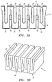
- Fig. 1 is a cross-sectional side view of an inkjet print head structure for a single ink channel according to an embodiment of the invention.
- Fig. 2 is a partial perspective view of the inkjet print head structure of Fig. 1.
- Fig. 3A is a front view of a portion of the structure of a sheet of transducer material for an array of ink channels according to the embodiment of the present invention shown in Fig. 2.
- Fig. 3B is a perspective view of the sheet of transducer material shown in Fig. 3A.
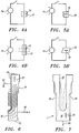
- Figs. 4A-B illustrate the normal mode actuation of a block of piezoelectric material.
- Figs. 5A-B illustrate the shear mode actuation of a block of piezoelectric material.
- Fig. 6 is a partial diagram of the preferred print head transducer structure showing electric fields established therein.
- Figs. 7 and 8 illustrate the mechanical movement of the transducer in the preferred print head structure constructed in accordance with the present invention.
- Fig. 9 depicts an alternate print head structure constructed in accordance with the present invention.
- Fig. 10 depicts an ink feed structure for an embodiment of the present invention.
- Fig. 11 shows the front view of an alternate print head transducer structure according to the present invention, wherein the addressable electrode metallization layer is not symmetrically coated on the first and second wall portions.
- Fig. 12 depicts the front view of a print head transducer according to an alternate embodiment of the present invention.
- Fig. 1 is a cross-sectional side view of a single channel of an inkjet print head structure 20 for a piezoelectric inkjet printer constructed in accordance with an embodiment of the present invention.
- Print head structure 20 comprises a print head transducer 2, formed of a piezoelectric material, into which is cut an ink channel 29.
- the ink channel 29 is bordered along one end with a nozzle plate 33 having an orifice 38 defined therethrough.
- a rear cover plate 48 is suitably secured to the other end of ink channel 29.
- a base portion 36 of the print head transducer 2 forms the floor of the ink channel 29, while an ink channel cover 31 is secured to the upper opening of the print head transducer 2.
- Ink channel 29 is supplied with ink from an ink reservoir 10 through ink feed passage 47 in rear cover plate 48. As explained in more detail below, the actuation of the print head transducer 2 results in the expulsion of ink drops from ink channel 29 though the orifice 38 in nozzle plate 33.
- the preferred print head transducer 2 comprises a first wall portion 32, a second wall portion 34, and a base portion 36.
- the upper surfaces of the first and second wall portions 32 and 34 define a first face 7 of the printed head transducer 2, and the lower surface of the base portion 36 defines a second, opposite face 9 of the print head transducer 2.
- Ink channel 29 is defined on three sides by the inner surface of the base portion 36 and the inner wall surfaces of the wall portions 32 and 34, and is an elongated channel cut into the piezoelectric material of the print head transducer 2, leaving a lengthwise opening along the upper first face 7 of the print head transducer 2.
- ink channel 29 is closed off by an nozzle plate 33 (Fig. 1) while the other end is closed off by a rear cover plate 48 (plates 33 and 48 are not shown in Fig. 2).
- a metallization layer 24 coats the inner surfaces of ink channel 29 and is also deposited along the upper surfaces of the first wall portion 32 and second wall portion 34.
- An ink channel cover 31 is bonded over the first face 7 of the print head transducer 2, to close off the lengthwise lateral opening in the ink channel 29.
- a second metallization layer 22 coats the outer surfaces of the base portion 36, and also extends approximately halfway up each of the outer surfaces of the first and second wall portions 32 and 34.
- the metallization layer 22 defines an addressable electrode 60, which is connected to an external signal source to provide electrical drive signals to actuate the piezoelectric material of print head transducer 2.
- the metallization layer 24 defines a common electrode 62 which is maintained at ground potential.
- the common electrode 62 may also be connected to an external voltage source to receive electrical drive signals.
- the preferred piezoelectric material forming the print head transducer 2 is PZT, although other piezoelectric materials may also be employed in the present invention.
- the overall polarization vector direction ("poling direction") of print head transducer 2 lies substantially in the direction shown by the arrow 30 in Fig. 2, extending in a perpendicular direction from the second face 9 to the first face 7 of the print head transducer 2.
- the print head transducer 2 may have other poling directions within the scope of the present invention, including, but not limited to, a poling direction which lies substantially opposite (approximately 180 degrees) to the direction indicated by the arrow 30 in Fig 2.
- print head transducer 2 is preferably formed from a single piece of piezoelectric material, rather than an assembly of separate components which are secured together into the desired structure (i.e., where the respective wall portions are distinct components which are bonded or glued to a separate base portion).
- the deflection capability of the print head transducer 2 is thus not limited by the strength or stiffness of glue lines or joints between different transducer components.
- the present invention works upon the principle of the piezoelectric effect, where the application of an electrical signal across certain faces of piezoelectric materials produces a corresponding mechanical distortion or strain in that material.
- the mechanical reaction of a piezoelectric material to an electrical signal is heavily dependent upon the poling direction of the piezoelectric material, as well as the orientation of the applied electrical field to that piezoelectric material.
- Figs. 4A and 4B depict the normal mode actuation of a typical piezoelectric material.
- the piezoelectric material 72 has a poling direction as indicated by arrow 70.
- a voltage source 74 is connected across two-exterior faces of piezoelectric material 72, with the voltage source 74 applying an electric field parallel to the poling direction 70 of the material 72.
- this electric field causes a normal mode mechanical distortion of the piezoelectric material 72, wherein one polarity of the applied voltage will cause material 72 to elongate, becoming longer and thinner parallel to the poling direction 70 of the piezoelectric material 72.
- the application of an opposite polarity voltage will cause material 72 to compress, becoming shorter and thicker, also parallel to the poling direction 70 of the piezoelectric material 72 (as shown in dashed lines in Fig. 4B).
- Figs. 5A and 5B depict the shear mode actuation of a typical piezoelectric material 76.
- the piezoelectric material 76 has a poling direction as indicated by arrow 78.
- the voltage source 74 is connected across the piezoelectric material 76 such that the application of voltage by the voltage source 74 creates an electric field which runs perpendicular to the poling direction of the piezoelectric material 76.
- this electric field causes a shear mode mechanical distortion of the piezoelectric material 76, which causes material 76 to generally react by deflecting towards a parallelogram shape, rather than the elongated or compressed reaction of the normal mode.
- the material 76 may deform in a bending or twisting manner.
- the particular direction, type of movement, and field of movement for this mechanical distortion is dictated in part by the shape, dimensions and/or composition of the piezoelectric material 76, and also by the amplitude, polarity or frequency of the electrical signal which is applied to the material 76.
- an applied voltage of one polarity will cause material 76 to bend in a first direction
- an applied voltage of the opposite polarity will cause material 76 to bend in a second direction opposite that of the first.
- Fig. 6 is a front view of one-half of the piezoelectric material for the preferred single channel print head transducer 2 (i.e., one wall portion and one-half of the base portion).
- metallization layer 24 is deposited on the interior surfaces of ink channel 29 and on the upper surface of the wall portion 34 to form the common electrode 62, which is preferably maintained at ground potential.
- Metallization layer 22 is coated over approximately half the outer surface of wall portion 34 and over the lower outer Surface of base portion 36 to define an addressable electrode 60, which is selectively connected to an electrical signal source to drive the print head transducer 2.
- the orientation of the applied electric field established in the transducer material is substantially as shown in Fig. 6.
- a substantial portion of the electric field generated between addressable electrode 60 and common electrode 62 is in the same direction as the poling direction 30 of piezoelectric material, thereby substantially actuating that portion of the transducer material in the normal mode.
- a substantial portion of the electric field generated between addressable electrode 60 and common electrode 62 is perpendicular to the poling direction 30, thereby substantially actuating that portion of the transducer in the shear mode toward the other lateral wall 32 (see Fig. 7).
- the electric field established between addressable electrode 60 and common electrode 62 changes in orientation, from the base portion 36 to the wall portion 34, substantially as shown in Fig. 6.
- Fig. 7 illustrates the movement of the transducer material in the preferred embodiment upon application of a positive voltage to the addressable electrode 60.
- the dashed lines in Fig. 7 indicate the directional extent of movement by the print head transducer 2 upon the application of a positive voltage. Since the material of base portion 36 is substantially actuated in the normal mode, that portion of the transducer material becomes elongated in a direction substantially parallel to the poling direction 30 of the piezoelectric material, inwardly into the ink channel 29. Since portions of the piezoelectric material of the wall portion 32 and 34 substantially deflect in the shear mode, the wall portion bend inward, substantially perpendicular to the poling direction 30 of the piezoelectric material.
- the application of positive voltage to electrode 60 results in the movement of the base portion 36 and wall portions 32 and 34 of the print head transducer 2 inward, toward the ink channel 29, resulting in a diminishment of the interior volume of the ink channel 29.
- the extent of transducer movement illustrated in. Fig. 7 has been exaggerated for clarity of explanation, and the particular range of movement actually produced by an embodiment of the present invention depends upon the particular parameters of the print head transducer and/or electrical drive signal employed.
- Fig. 8 illustrates the movement of transducer material in the preferred embodiment upon application of negative voltage to the addressable electrode 60.
- the dashed lines in Fig. 8 indicate the directional extent of movement by the transducer material upon the application of voltage to the electrode 60.
- the material of base portion 36 is substantially actuated in the normal mode, that portion of the transducer material becomes shorter and wider.
- Portions of the piezoelectric material of wall portion 32 and 34 are actuated in the shear mode, and thus, the wall portions bend outward, away from the ink channel 29. Therefore, the application of negative voltage results in a net volume increase in the interior area of the ink channel 29.
- the extent of transducer movement illustrated in Fig. 8 has been exaggerated for clarity of explanation, and the particular range of movement actually produced by an embodiment of the present invention depends upon the particular parameters of the print head transducer and/or electrical drive signal employed.
- the application of an electrical drive signal to the addressable electrode 60 of the print head transducer 2 causes a mechanical movement or distortion of the walls of the ink channel 29, resulting in a volume change within the ink channel 29.
- This change in volume within the ink channel 29 generates an acoustic pressure wave within ink channel 29, and this pressure wave within the ink channel 29 provides energy to expel ink from orifice 38 of print head structure 20 onto a print medium.
- the parameters of an applied electrical drive signal may significantly affect the mechanical movement of the print head transducer structure, which affects the characteristics of the acoustic pressure wave(s) acting within the ink channel 29, which in turn affects the size, volume, shape, speed, and/or quality of the ink drop expelled from the print head 20. Details of the preferred method to operate print head structure 20 are disclosed in copending application serial no.
- the print head structure 20 is preferably operated with variable amplitude multi-pulse sinusoidal input waveforms at the resonant frequency of the ink channel 29, which allows the expulsion of variable volume ink drops from the print head structure 20 at substantially constant drop speeds.
- an alternative embodiment of the present invention comprising a print head transducer 102 wherein the metallization layer forming the addressable electrode 104 is not symmetrically coated over the exterior surfaces of the first and second side wall portions 106 and 108.
- the addressable electrode metallization layer 104 coated on the first side wall portion 106 extends to a height H1, while the coating at the second side wall portion 108 extends to a height H2, where H1 and H2 are not equal.
- H1 and H2 are not equal.
- a-print head transducer 110 has an addressable electrode metallization layer 118 which coats only one-half of the exterior surface of the base portion 112 along with the exterior surface of only a single wall portion 116.
- the application of voltage to the addressable electrode 118 will significantly actuate only half the print head transducer structure 110.
- a multiple-channel inkjet print head constructed in accordance with the present invention comprises an array of print head structures 20, each having an ink channel 29 in the array linearly adjacent and substantially parallel to its neighboring ink channel 29.
- a single block, sheet, or wafer of piezoelectric material 21 is preferably used to manufacture the transducer portion of the array of ink channels.
- Figs. 3A and 3B show a portion of piezoelectric sheet 21 into which a series of substantially identical and generally parallel ink channels 29 have been cut into a first face 51 of sheet 21.
- a series of substantially identical and generally parallel air channels 50 are cut into a second face 53, with each air channel 50 interspaced between an adjacent ink channel 29.
- the air channels 50 are initially cut to a depth approximately halfway along the cut depth of each ink channel 29, to approximately the relative distance marked by dashed lines 54 in Fig. 3A.
- a metallization layer 24, defining common electrode 62, is deposited onto the inner surfaces and interior end of each ink channel 29, and over the first face 51 of sheet 21.
- Metallization layer 24 is connected continuously from ink channel to ink channel, and is preferably maintained at ground potential.
- Another metallization layer 22, defining the addressable electrodes 60 is deposited onto the inner surfaces and interior end of each air channel 50 (up to and including the surface marked by dashed lines 54) and over the second face 53 of sheet 21, with the metallization layer 22 initially connected from air channel to air channel at the bottom 54 of each air channel 50.
- An electrode-separation channel 52 is then cut into each air channels 50, which also breaks the connection between the individual metallization layers 22 within each air channel 50.
- the metallization layer 22 for each addressable electrode 60 is a discrete element, and the addressable electrodes 60 can then be separately and selectively connected to an electrical drive signal source.
- the electrode-separation channel 52 significantly extends the cut gap created by the combined cut depths of the air channel 50 and the electrode-separation channel 52 towards the first face 51 of piezoelectric sheet 21.
- this method of manufacture results in the metallization layer 22 forming addressable electrode 60 extending down each air channel 50 to a position corresponding to approximately half the total cut depth of the adjacent ink channel 29. If the metallization layer 22 extends to a position which is too far towards the first face 51 of sheet 21, then the actuation of the transducer material in the shear mode may cause the wall portions 32 and 34 to bend both towards and away from the interior of ink channel 29 at the same time, resulting in less than optimal volume displacement of the ink channel 29.
- the metallization layer 22 does not extend far enough towards the first face 51, then the actuation of the transducer material will not produce the desired maximal movement of the wall portions 32 and 34, again resulting in less than optimal volume displacement of the ink channels 29.
- the above-disclosed metallization depth for the addressable electrodes may differ depending upon the specific application or print head configuration in which the present invention is utilized.
- the electrode-separation channel 52, the air channels 50, and the ink channels 29 are all preferably cut with interior end-surfaces having a rounded bottom.
- the lower cross-section of the base portion 36 of print head transducer 2 preferably has a rectangular shape when viewed from the front.
- the combination of the physical geometry of a rectangularly shaped cross-section for the base portion 36, along with the particular shape and orientation of the generated electric field resulting from a rectangularly shaped base portion 36, provides for an efficient combination of shear and normal mode actuation of the print head transducer 2.
- a rectangular cross-sectional shape results in the lower surface of base portion 36 having a relatively wide lower surface area on which to deposit a metallization layer 22 to form the addressable electrode 60.
- the relatively wide surface area on the lower surface of the base portion 36 provides for a greater portion of the electric field created between the addressable and common electrodes at the base portion 36 to have an orientation which actuates the base portion 36 in the normal mode, i.e., electric field orientation which is substantially parallel to the poling direction 30.
- the lower cross-section of base portion 36 can be formed in the shape of an inverted trapezoid, wherein the outer walls of the base portion 36 slant inward, toward each other, thereby narrowing the width of the lower surface of the base portion 36.
- This embodiment is less preferred than the above-described rectangular shape, since less surface areas is available along the lower surface of base portion 36 for the addressable electrode metallization layer, and the physical geometry is less efficient for actuation of the print head.
- a base portion having a lower cross-section in the shape of an inverted triangle is much less preferred than a rectangular shape, since the geometry is less efficient for actuating the print head, and since less lower surface area is available for deposition of an addressable electrode metallization layer, thereby decreasing efficient normal mode actuation of the base portion 36.
- the height H of the base portion 36 is preferably equal to the width W of the wall portions 32 and 34.
- the present invention can be practiced with other height dimensions for base portion 36, and alternatively preferred embodiments comprise a base height range of approximately 0.5 to 5 times the width W of wall portions 32 and 34.
- An alternate embodiment of the present invention further comprises a base cover plate 61 which is bonded or glued to the lower outer surface of the base portion 36 (Fig. 9).
- the base cover plate 61 enhances the movement of the normal mode deflection of the base portion 36 when the print head transducer 2 is actuated.
- the material of the base portion has a tendency to deform in an elongated manner parallel to the poling direction 30, with the upper surface of the base portion 36 elongating upward toward the ink channel 29, and the lower surface of the base portion 36 elongating downward, away from the ink channel 29.
- the base cover plate 61 provides a restraining force on the outer lower surface of base 36, resisting the movement of the lower surface of the base portion 36.
- the physical result of the restraining force applied by the base cover plate 61 is for the upper surface of base portion 36 to further elongate upward, increasing the volume displacement within ink channel 29 by enhancing the distance that the base portion 36 elongates into the ink channel 29.
- the base cover plate 61 restrains the tendency of the lower surface of the base portion 36 to deform in a compressive manner.
- the base portion 36 physically compensates for this restraining force by increasing the movement of the upper surface of the base portion 36 downward, away from the ink channel 29, thereby enhancing the volume change within the ink channel 29 from the normal mode deflection of the base portion 36.
- metallization layers 22 and 24 are formed of gold, and are sputter-deposited onto the piezoelectric sheet 21.
- the cuts made in the piezoelectric sheet 21 are preferably made with diamond saws, utilizing techniques and apparatuses familiar to those skilled in the semiconductor integrated circuit manufacturing arts.
- the ink channel cover 31 is preferably glued or bonded to the metallization layer 24 on the upper surface of sheet 21 to close off the ink channels 29.
- the nozzle plate 33 and rear cover plate 48 are preferably glued or bonded to the front and rear surfaces of sheet 21, respectively.
- the ink channel cover 31, base cover plate 61, and nozzle plate 33 should preferably be formed of a material having a coefficient of thermal expansion compatible with each other.
- the nozzle is formed of gold-plated nickel in the preferred embodiment, although other materials such as PZT are within the scope of this invention.
- the ink channel cover 31 and base cover plate 61 are preferably formed of PZT, although other materials may also be appropriately used within the scope of this invention, including but not limited to silicon, glass, and various metallic materials.
- An advantageous aspect of the present invention is that a multiple-channel print head can be formed from a single sheet of piezoelectric material that has been pre-polarized in an appropriate poling direction prior to manufacture of the print head structure 20.
- This ability to manufacture with a pre-polarized block of material is a significant advantage over the prior art piezoelectric print head structures, which may require the polarization of the piezoelectric material later in the manufacturing cycle.
- a pre-polarized sheet of piezoelectric material more consistency is obtained with regard to the overall polarization of the piezoelectric material employed.
- a pre-polarized sheet of piezoelectric material can be thoroughly tested for the appropriate piezoelectric properties prior to machining, rather than after the expense and efforts of machining have already been performed on a particular sheet of piezoelectric material.
- the alternating air/ink channel design of the preferred print head serves to reduce mechanical crosstalk between adjacent ink channels normally resulting from the motion of the actuated piezoelectric transducer material.
- the preferred embodiment allows a densely packed array of ink channels to be placed together, this structure also tends to reduce interference which may occur from one ink channel to the next.
- This favorable reduction in crosstalk in the preferred design is due to the comparatively small extent of mechanical coupling between the adjacent ink channels, and is also due to the insulating properties of the cut gap formed by the combined air channels 50 and electrode separation channels 52.
- a protective ink feed structure to supply ink from the ink reservoir 10 to the ink channel 29.
- Fig. 10 is a view of the rear of print head structure 20, showing the path of a central ink feed passage 49, which may be formed as part of rear cover plate 48 (not shown in Fig. 10), that extends from the ink reservoir 10 the individual ink channels 29.
- Each slotted passageway 47 extends from the central ink feed passage 49 to each ink channel 29.
- Each slotted passageway 47 is a grooved indentation formed in the rear cover plate 48, extending in length from the ink feed passageway 49 to the bottom of each ink channel 29.
- Each slotted passageway 47 in rear cover plate 48 has a tapering curve along its length substantially as shown in Fig. 1.
- Each slotted passageway 47 preferably has a slot width which is approximately the same width as the ink channels 29.
- ink is constantly supplied to the central ink supply passage 49 from the ink reservoir 10, and when required by an individual ink channel 29, the ink is then drawn from the ink supply passage 49 through a slotted passageway 47 into the ink channel 29 by the pressure difference caused by the movement of the print head transducer 2, along with the pressure difference caused by the surface tension forces of the meniscus at the ink channel orifice.
- the use of slots or slotted passageway to supply ink to an ink channel, such as slotted passageway 47 helps to reduce the amplitude of pressure waves which escape the ink channels 29, reducing the probably that the escaping pressure waves will affect the operation of neighboring ink channels.
- slotted passageways 49 This is in due in part to the length of the slotted passageways 49, which increases the distance that a pressure wave must travel to affect a neighboring ink channel 29, thereby diminishing the strength of the escaping pressure waves.
- the slotted passageways 49 are small enough in width to substantially prevent high frequency pressure waves from intruding into other ink channels.
- Table I are acceptable parameters for the block 21 of piezoelectric material forming the transducer for the preferred embodiment: Structure Dimension A. Thickness of PZT sheet 0.0240 in. B. Cut width of ink channel 0.0030 in. C. Cut depth of ink channel 0.0193 in. D. Length of ink channel 0.2000 in. E. Cut width of air channel 0.0030 in. F. Cut depth of air channel 0.0118 in. G. Cut width of electrode-separation channel 0.0020 in. H. Cut depth of combined air channel and electrode-separation channel 0.0213 in. I. Distance from ink channel center to adjacent ink channel center 0.0100 in. J. Distance from ink channel center to adjacent air channel center 0.0050 in. K. Diameter of orifice in nozzle plate 0.0014 in.
Landscapes
- Engineering & Computer Science (AREA)
- Manufacturing & Machinery (AREA)
- Particle Formation And Scattering Control In Inkjet Printers (AREA)
Applications Claiming Priority (2)
| Application Number | Priority Date | Filing Date | Title |
|---|---|---|---|
| US70392496A | 1996-08-27 | 1996-08-27 | |
| US703924 | 1996-08-27 |
Publications (2)
| Publication Number | Publication Date |
|---|---|
| EP0827833A2 true EP0827833A2 (fr) | 1998-03-11 |
| EP0827833A3 EP0827833A3 (fr) | 1999-01-20 |
Family
ID=24827333
Family Applications (1)
| Application Number | Title | Priority Date | Filing Date |
|---|---|---|---|
| EP97112172A Withdrawn EP0827833A3 (fr) | 1996-08-27 | 1997-07-16 | Dispositif de tête à jet d'encre |
Country Status (8)
| Country | Link |
|---|---|
| US (1) | US5901425A (fr) |
| EP (1) | EP0827833A3 (fr) |
| JP (1) | JPH1086369A (fr) |
| KR (1) | KR19980018995A (fr) |
| AU (1) | AU3530197A (fr) |
| CA (1) | CA2211238A1 (fr) |
| SG (1) | SG65011A1 (fr) |
| TW (1) | TW403701B (fr) |
Cited By (26)
| Publication number | Priority date | Publication date | Assignee | Title |
|---|---|---|---|---|
| WO1999003683A1 (fr) | 1997-07-16 | 1999-01-28 | Topaz Technologies, Inc. | Densitometre monte sur chariot |
| WO1999011461A1 (fr) * | 1997-08-29 | 1999-03-11 | Topaz Technologies, Inc. | Ensemble tete integree pour imprimante a jet d'encre |
| EP0943439A3 (fr) * | 1998-03-17 | 2000-04-12 | Eastman Kodak Company | Imprimante adaptée pour réduire les interférences entre canaux à encre et procédé correspondant |
| EP0940256A3 (fr) * | 1998-03-06 | 2000-05-24 | Eastman Kodak Company | Appareil d'impression capable de faire varier la direction d'une gouttelette d'encre devant en être éjectée et son procédé de fonctionnement |
| EP1002647A2 (fr) | 1998-11-17 | 2000-05-24 | Eastman Kodak Company | Procédé et dispositif d'électroformage pour plaque à orifices à jet d'encre |
| EP1008450A2 (fr) | 1998-12-10 | 2000-06-14 | Eastman Kodak Company | Impression à jet d'encre pour formats variables |
| US6076917A (en) * | 1998-09-30 | 2000-06-20 | Eastman Kodak Company | Ink jet printing of color image and annotations |
| US6126283A (en) * | 1998-10-29 | 2000-10-03 | Eastman Kodak Company | Format flexible ink jet printing |
| EP1046505A1 (fr) * | 1999-04-19 | 2000-10-25 | Océ-Technologies B.V. | Tête d'impression à jet d'encre |
| EP1046506A1 (fr) * | 1999-04-19 | 2000-10-25 | Océ-Technologies B.V. | Tête d'impression à jet d'encre |
| EP1057631A1 (fr) | 1999-06-03 | 2000-12-06 | Eastman Kodak Company | Appareil pour former des couches texturées sur des images |
| EP1013428A3 (fr) * | 1998-12-25 | 2000-12-06 | Matsushita Electric Industrial Co., Ltd. | Tête d'impression à jet d'encre |
| US6161270A (en) * | 1999-01-29 | 2000-12-19 | Eastman Kodak Company | Making printheads using tapecasting |
| US6168746B1 (en) | 1999-02-22 | 2001-01-02 | Eastman Kodak Company | Injection molding of ferroelectric articles |
| US6170943B1 (en) | 1998-10-29 | 2001-01-09 | Eastman Kodak Company | Large and small format ink jet printing apparatus |
| US6209999B1 (en) | 1998-12-23 | 2001-04-03 | Eastman Kodak Company | Printing apparatus with humidity controlled receiver tray |
| US6214192B1 (en) | 1998-12-10 | 2001-04-10 | Eastman Kodak Company | Fabricating ink jet nozzle plate |
| US6214245B1 (en) | 1999-03-02 | 2001-04-10 | Eastman Kodak Company | Forming-ink jet nozzle plate layer on a base |
| US6217167B1 (en) | 1998-12-11 | 2001-04-17 | Eastman Kodak Company | Ink jet printing having format flexibility and reduced receiver waste |
| US6238584B1 (en) | 1999-03-02 | 2001-05-29 | Eastman Kodak Company | Method of forming ink jet nozzle plates |
| US6254819B1 (en) | 1999-07-16 | 2001-07-03 | Eastman Kodak Company | Forming channel members for ink jet printheads |
| US6258286B1 (en) | 1999-03-02 | 2001-07-10 | Eastman Kodak Company | Making ink jet nozzle plates using bore liners |
| US6303042B1 (en) | 1999-03-02 | 2001-10-16 | Eastman Kodak Company | Making ink jet nozzle plates |
| US6334677B1 (en) | 1998-12-11 | 2002-01-01 | Eastman Kodak Company | Format flexible ink jet printing having efficient receiver usage |
| US6394577B1 (en) | 1999-08-19 | 2002-05-28 | Eastman Kodak Company | Ink jet printing on a receiver attached to a drum |
| US6428157B1 (en) | 1999-06-03 | 2002-08-06 | Eastman Kodak Company | Forming ink images having protection films |
Families Citing this family (22)
| Publication number | Priority date | Publication date | Assignee | Title |
|---|---|---|---|---|
| JPH11157065A (ja) * | 1997-11-27 | 1999-06-15 | Fujitsu Ltd | インクジェットヘッド |
| CN1182966C (zh) | 1999-08-14 | 2005-01-05 | 萨尔技术有限公司 | 用于液滴沉积装置的元件及其制造方法 |
| US6755511B1 (en) * | 1999-10-05 | 2004-06-29 | Spectra, Inc. | Piezoelectric ink jet module with seal |
| US6513894B1 (en) | 1999-11-19 | 2003-02-04 | Purdue Research Foundation | Method and apparatus for producing drops using a drop-on-demand dispenser |
| US6561607B1 (en) | 2000-10-05 | 2003-05-13 | Eastman Kodak Company | Apparatus and method for maintaining a substantially constant closely spaced working distance between an inkjet printhead and a printing receiver |
| US6428135B1 (en) | 2000-10-05 | 2002-08-06 | Eastman Kodak Company | Electrical waveform for satellite suppression |
| US6450602B1 (en) | 2000-10-05 | 2002-09-17 | Eastman Kodak Company | Electrical drive waveform for close drop formation |
| US7052117B2 (en) | 2002-07-03 | 2006-05-30 | Dimatix, Inc. | Printhead having a thin pre-fired piezoelectric layer |
| US8491076B2 (en) | 2004-03-15 | 2013-07-23 | Fujifilm Dimatix, Inc. | Fluid droplet ejection devices and methods |
| US7281778B2 (en) | 2004-03-15 | 2007-10-16 | Fujifilm Dimatix, Inc. | High frequency droplet ejection device and method |
| GB0415529D0 (en) * | 2004-07-10 | 2004-08-11 | Xaar Technology Ltd | Droplet deposition apparatus |
| EP1836056B1 (fr) | 2004-12-30 | 2018-11-07 | Fujifilm Dimatix, Inc. | Impression a jet d'encre |
| GB0514202D0 (en) * | 2005-07-11 | 2005-08-17 | Xaar Technology Ltd | Droplet deposition apparatus |
| US8733274B2 (en) * | 2006-10-20 | 2014-05-27 | Hewlett-Packard Development Company, L.P. | Tube mounted inkjet printhead die |
| US7988247B2 (en) | 2007-01-11 | 2011-08-02 | Fujifilm Dimatix, Inc. | Ejection of drops having variable drop size from an ink jet printer |
| US8186790B2 (en) * | 2008-03-14 | 2012-05-29 | Purdue Research Foundation | Method for producing ultra-small drops |
| JP5925067B2 (ja) * | 2012-06-22 | 2016-05-25 | キヤノン株式会社 | 液体吐出ヘッド |
| JP6322369B2 (ja) | 2013-07-18 | 2018-05-09 | エスアイアイ・プリンテック株式会社 | 液体噴射ヘッド、液体噴射装置及び液体噴射ヘッドの製造方法 |
| JP6209383B2 (ja) | 2013-07-24 | 2017-10-04 | エスアイアイ・プリンテック株式会社 | 液体噴射ヘッド、液体噴射装置及び液体噴射ヘッドの製造方法 |
| JP6278692B2 (ja) | 2013-12-24 | 2018-02-14 | エスアイアイ・プリンテック株式会社 | 液体噴射ヘッド及び液体噴射装置 |
| JP7689066B2 (ja) * | 2021-12-10 | 2025-06-05 | 理想テクノロジーズ株式会社 | 液体吐出ヘッド |
| CN117366989A (zh) * | 2023-10-10 | 2024-01-09 | 美级(北京)科技有限公司 | 一种水冷换能器 |
Family Cites Families (517)
| Publication number | Priority date | Publication date | Assignee | Title |
|---|---|---|---|---|
| CH547713A (de) * | 1969-04-23 | 1974-04-11 | Ananda Anlageanst | Verfahren zur herstellung einer kugelschreibermine. |
| JPS4836188Y1 (fr) * | 1969-05-19 | 1973-10-30 | ||
| US3667678A (en) * | 1970-03-13 | 1972-06-06 | Ibm | Nozzle structure for jet printers |
| US4339763A (en) * | 1970-06-29 | 1982-07-13 | System Industries, Inc. | Apparatus for recording with writing fluids and drop projection means therefor |
| US3776461A (en) * | 1971-10-04 | 1973-12-04 | Casio Computer Co Ltd | Nozzle device for ink jet printing equipments |
| SE371901B (fr) * | 1973-12-28 | 1974-12-02 | Facit Ab | |
| CH581357A5 (fr) * | 1974-03-12 | 1976-10-29 | Facit Ab | |
| US3927410A (en) * | 1974-04-30 | 1975-12-16 | Ibm | Ink jet nozzle |
| US3955953A (en) * | 1974-07-31 | 1976-05-11 | Teletype Corporation | Methods of making self filtering nozzles |
| US4095237A (en) * | 1974-12-26 | 1978-06-13 | Aktiebolaget Electrolux | Ink jet printing head |
| US3921916A (en) * | 1974-12-31 | 1975-11-25 | Ibm | Nozzles formed in monocrystalline silicon |
| US3958255A (en) * | 1974-12-31 | 1976-05-18 | International Business Machines Corporation | Ink jet nozzle structure |
| US4007464A (en) * | 1975-01-23 | 1977-02-08 | International Business Machines Corporation | Ink jet nozzle |
| JPS51142230A (en) * | 1975-06-03 | 1976-12-07 | Ricoh Co Ltd | Device for jetting ink |
| US4002230A (en) * | 1975-07-09 | 1977-01-11 | Houston Engineering Research Corporation | Print head apparatus |
| SE390673B (sv) * | 1975-07-23 | 1977-01-03 | Facit Ab | Skrivhuvud for en bleckstraleskrivare |
| US4008111A (en) * | 1975-12-31 | 1977-02-15 | International Business Machines Corporation | AlN masking for selective etching of sapphire |
| US4047186A (en) * | 1976-01-26 | 1977-09-06 | International Business Machines Corporation | Pre-aimed nozzle for ink jet recorder and method of manufacture |
| DE2604939C3 (de) * | 1976-02-09 | 1978-07-27 | Ibm Deutschland Gmbh, 7000 Stuttgart | Verfahren zum Herstellen von wenigstens einem Durchgangsloch insbesondere einer Düse für Tintenstrahldrucker |
| US4106976A (en) * | 1976-03-08 | 1978-08-15 | International Business Machines Corporation | Ink jet nozzle method of manufacture |
| US4025928A (en) * | 1976-04-19 | 1977-05-24 | Gould Inc. | Unitary ink jet and reservoir |
| DE2626420C3 (de) * | 1976-06-12 | 1979-11-29 | Ibm Deutschland Gmbh, 7000 Stuttgart | Verfahren zum gleichzeitigen Ätzen von mehreren durchgehenden Löchern |
| US4112170A (en) * | 1976-12-13 | 1978-09-05 | Corning Glass Works | Composite glass articles for channel plate fabrication |
| US4153901A (en) * | 1976-12-20 | 1979-05-08 | Recognition Equipment Incorporated | Variable frequency multi-orifice IJP |
| DE2659398A1 (de) * | 1976-12-29 | 1978-07-06 | Siemens Ag | Heizvorrichtung fuer schreibkoepfe in tintenmosaikschreibeinrichtungen |
| US4112436A (en) * | 1977-02-24 | 1978-09-05 | The Mead Corporation | Glass nozzle array for an ink jet printer and method of forming same |
| USRE31357E (en) * | 1977-02-24 | 1983-08-23 | The Mead Corporation | Glass nozzle array for an ink jet printer and method of forming same |
| US4121227A (en) * | 1977-03-14 | 1978-10-17 | Xerox Corporation | Ink jet array with isolated fluid rectifier layers |
| US4169008A (en) * | 1977-06-13 | 1979-09-25 | International Business Machines Corporation | Process for producing uniform nozzle orifices in silicon wafers |
| DE2728657A1 (de) * | 1977-06-24 | 1979-01-04 | Siemens Ag | Duesenplatte fuer tintenschreibeinrichtungen |
| US4106975A (en) * | 1977-06-30 | 1978-08-15 | International Business Machines Corporation | Process for etching holes |
| US4122460A (en) * | 1977-08-10 | 1978-10-24 | International Business Machines Corporation | Ink jet nozzle structures |
| US4123571A (en) * | 1977-09-08 | 1978-10-31 | International Business Machines Corporation | Method for forming smooth self limiting and pin hole free SiC films on Si |
| CA1127227A (fr) | 1977-10-03 | 1982-07-06 | Ichiro Endo | Procede d'enregistrement a jet liquide et appareil d'enregistrement |
| US4146899A (en) * | 1977-10-13 | 1979-03-27 | The Mead Corporation | Formed orifice plate for ink jet printing apparatus |
| US4185290A (en) * | 1977-12-22 | 1980-01-22 | International Business Machines Corporation | Compensation for aerodynamic drag on ink streams from a multi-nozzle ink array |
| US4157935A (en) * | 1977-12-23 | 1979-06-12 | International Business Machines Corporation | Method for producing nozzle arrays for ink jet printers |
| US4187140A (en) * | 1978-10-11 | 1980-02-05 | International Business Machines Corporation | Method for etching silicon and a residue and oxidation resistant etchant therefor |
| US4296421A (en) * | 1978-10-26 | 1981-10-20 | Canon Kabushiki Kaisha | Ink jet recording device using thermal propulsion and mechanical pressure changes |
| US4330787A (en) | 1978-10-31 | 1982-05-18 | Canon Kabushiki Kaisha | Liquid jet recording device |
| US4245225A (en) * | 1978-11-08 | 1981-01-13 | International Business Machines Corporation | Ink jet head |
| US4222060A (en) * | 1978-11-20 | 1980-09-09 | Ricoh Company, Ltd. | Ink jet printing apparatus |
| US4248823A (en) * | 1978-12-15 | 1981-02-03 | Ncr Corporation | Method of making ink jet print head |
| US4281333A (en) * | 1979-02-14 | 1981-07-28 | Nippon Electric Co., Ltd. | Ink-on-demand type ink-jet printer with coordinated variable size drops with variable charges |
| JPS5830830B2 (ja) * | 1979-02-23 | 1983-07-01 | 株式会社リコー | インクジェット用マルチノズルヘッド |
| AU531269B2 (en) | 1979-03-06 | 1983-08-18 | Canon Kabushiki Kaisha | Ink jet printer |
| DE3011919A1 (de) * | 1979-03-27 | 1980-10-09 | Canon Kk | Verfahren zur herstellung eines aufzeichnungskopfes |
| US4335389A (en) * | 1979-03-27 | 1982-06-15 | Canon Kabushiki Kaisha | Liquid droplet ejecting recording head |
| US5204689A (en) | 1979-04-02 | 1993-04-20 | Canon Kabushiki Kaisha | Ink jet recording head formed by cutting process |
| US4334234A (en) * | 1979-04-02 | 1982-06-08 | Canon Kabushiki Kaisha | Liquid droplet forming apparatus |
| JPS593152B2 (ja) * | 1979-05-30 | 1984-01-23 | 株式会社リコー | 微細孔形成方法 |
| US4301585A (en) * | 1979-05-31 | 1981-11-24 | Ricoh Co., Ltd. | Method of forming plate having fine bores |
| US4224627A (en) * | 1979-06-28 | 1980-09-23 | International Business Machines Corporation | Seal glass for nozzle assemblies of an ink jet printer |
| US4239586A (en) * | 1979-06-29 | 1980-12-16 | International Business Machines Corporation | Etching of multiple holes of uniform size |
| US4336548A (en) * | 1979-07-04 | 1982-06-22 | Canon Kabushiki Kaisha | Droplets forming device |
| US4257052A (en) * | 1979-10-29 | 1981-03-17 | The Mead Corporation | Molded orifice plate assembly for an ink jet recorder and method of manufacture |
| US4246076A (en) * | 1979-12-06 | 1981-01-20 | Xerox Corporation | Method for producing nozzles for ink jet printers |
| JPS5689569A (en) * | 1979-12-19 | 1981-07-20 | Canon Inc | Ink jet recording head |
| US4430784A (en) * | 1980-02-22 | 1984-02-14 | Celanese Corporation | Manufacturing process for orifice nozzle devices for ink jet printing apparati |
| US4282533A (en) * | 1980-02-22 | 1981-08-04 | Celanese Corporation | Precision orifice nozzle devices for ink jet printing apparati and the process for their manufacture |
| DE3006726C2 (de) * | 1980-02-22 | 1982-03-11 | Siemens AG, 1000 Berlin und 8000 München | Tintenschreibeinrichtung |
| US4417251A (en) * | 1980-03-06 | 1983-11-22 | Canon Kabushiki Kaisha | Ink jet head |
| DE3019822A1 (de) * | 1980-05-23 | 1981-12-03 | Siemens AG, 1000 Berlin und 8000 München | Anordnung fuer einen schreibkopf in tintenmosaikschreibeinrichtungen |
| US4409596A (en) * | 1980-08-12 | 1983-10-11 | Epson Corporation | Method and apparatus for driving an ink jet printer head |
| DE3170847D1 (en) * | 1980-09-08 | 1985-07-11 | Epson Corp | Ink jet head |
| US4338611A (en) * | 1980-09-12 | 1982-07-06 | Canon Kabushiki Kaisha | Liquid jet recording head |
| JPS5764563A (en) * | 1980-10-07 | 1982-04-19 | Fuji Xerox Co Ltd | Ink particle jet apparatus of multi-nozzle ink jet printer |
| US4343013A (en) * | 1980-10-14 | 1982-08-03 | Ncr Corporation | Nozzle plate for ink jet print head |
| US4429321A (en) * | 1980-10-23 | 1984-01-31 | Canon Kabushiki Kaisha | Liquid jet recording device |
| AT368283B (de) * | 1980-11-07 | 1982-09-27 | Philips Nv | Duesenplatte fuer einen tintenstrahlschreibkopf und verfahren zur herstellung einer solchen duesen- platte |
| US4437109A (en) * | 1980-11-07 | 1984-03-13 | General Electric Company | Silicon-on-sapphire body with conductive paths therethrough |
| DE3042483A1 (de) * | 1980-11-11 | 1982-06-16 | Philips Patentverwaltung Gmbh, 2000 Hamburg | Verfahren und anordnung zur herstellung einer duesenplatte fuer tintenstrahlschreibwerke |
| AT372651B (de) * | 1980-12-15 | 1983-11-10 | Philips Nv | Tintenstrahlschreibkopf und verfahren zur herstellung eines solchen tintenstrahlschreibkopfes |
| JPS57102366A (en) * | 1980-12-18 | 1982-06-25 | Canon Inc | Ink jet head |
| DE3048259A1 (de) * | 1980-12-20 | 1982-07-29 | Philips Patentverwaltung Gmbh, 2000 Hamburg | "duese fuer tintenstrahldrucker" |
| JPS57109669A (en) * | 1980-12-27 | 1982-07-08 | Ricoh Co Ltd | Ink injection head |
| US4394670A (en) * | 1981-01-09 | 1983-07-19 | Canon Kabushiki Kaisha | Ink jet head and method for fabrication thereof |
| JPS57131567A (en) * | 1981-01-16 | 1982-08-14 | Ricoh Co Ltd | Nozzle for ink jet printer |
| DE3104077A1 (de) * | 1981-02-06 | 1982-09-09 | Philips Patentverwaltung Gmbh, 2000 Hamburg | "schreibkopf fuer tintenstrahldrucker" |
| US4392145A (en) * | 1981-03-02 | 1983-07-05 | Exxon Research And Engineering Co. | Multi-layer ink jet apparatus |
| US4374707A (en) * | 1981-03-19 | 1983-02-22 | Xerox Corporation | Orifice plate for ink jet printing machines |
| DE3113239A1 (de) * | 1981-04-02 | 1982-10-21 | Philips Patentverwaltung Gmbh, 2000 Hamburg | "verfahren zur herstellung und anordnung eines tintenstrahldruckers" |
| US4376944A (en) * | 1981-04-13 | 1983-03-15 | Ncr Corporation | Ink jet print head with tilting nozzle |
| NL8102026A (nl) * | 1981-04-24 | 1982-11-16 | Philips Nv | Werkwijze voor het vervaardigen van schrijfkoppen voor inktstraaldrukkers en schrijfkop vervaardigd volgens die werkwijze. |
| JPS57181875A (en) * | 1981-05-06 | 1982-11-09 | Nec Corp | Ink jet head and ink jet recording device |
| JPS57182449A (en) * | 1981-05-07 | 1982-11-10 | Fuji Xerox Co Ltd | Forming method of ink jet multinozzle |
| US4429317A (en) * | 1981-05-19 | 1984-01-31 | Ricoh Company, Ltd. | Ink ejection head |
| US4450455A (en) * | 1981-06-18 | 1984-05-22 | Canon Kabushiki Kaisha | Ink jet head |
| US4437100A (en) * | 1981-06-18 | 1984-03-13 | Canon Kabushiki Kaisha | Ink-jet head and method for production thereof |
| GB2104452B (en) | 1981-06-29 | 1985-07-31 | Canon Kk | Liquid jet recording head |
| US4558333A (en) | 1981-07-09 | 1985-12-10 | Canon Kabushiki Kaisha | Liquid jet recording head |
| US4631553A (en) | 1981-07-17 | 1986-12-23 | Ricoh Company, Ltd. | Printer head of an ink-jet printer |
| JPS5816856A (ja) * | 1981-07-24 | 1983-01-31 | Fuji Photo Film Co Ltd | インクジエツト用ノズルヘツド |
| JPS5833472A (ja) * | 1981-08-24 | 1983-02-26 | Canon Inc | 液体噴射記録ヘツド |
| US4390883A (en) * | 1981-09-08 | 1983-06-28 | The Mead Corporation | Fluid jet print head and method of terminating operation thereof |
| US4418356A (en) * | 1981-09-23 | 1983-11-29 | Ncr Corporation | Ink jet print head |
| US4389654A (en) * | 1981-10-01 | 1983-06-21 | Xerox Corporation | Ink jet droplet generator fabrication method |
| US4499480A (en) | 1981-10-13 | 1985-02-12 | Canon Kabushiki Kaisha | Liquid jet recording device |
| US4415909A (en) * | 1981-10-26 | 1983-11-15 | Ncr Corporation | Multiple nozzle ink jet print head |
| US4449135A (en) * | 1981-12-23 | 1984-05-15 | Ricoh Company, Ltd. | Ink ejection head |
| US4611219A (en) | 1981-12-29 | 1986-09-09 | Canon Kabushiki Kaisha | Liquid-jetting head |
| US4424521A (en) * | 1982-01-04 | 1984-01-03 | Exxon Research And Engineering Co. | Ink jet apparatus and reservoir |
| US4429322A (en) * | 1982-02-16 | 1984-01-31 | Mead Corporation | Method of fabricating a glass nozzle array for an ink jet printing apparatus |
| US4446469A (en) * | 1982-03-31 | 1984-05-01 | Xerox Corporation | Ink jet printer array |
| DE3311956A1 (de) | 1982-03-31 | 1983-10-13 | Ricoh Co., Ltd., Tokyo | Farbstrahl-druckerkopf |
| US4414553A (en) * | 1982-03-31 | 1983-11-08 | Xerox Corporation | Ink jet array |
| JPS58220754A (ja) | 1982-06-18 | 1983-12-22 | Canon Inc | インクジエツト記録ヘツド |
| JPS58220757A (ja) | 1982-06-18 | 1983-12-22 | Canon Inc | 液体噴射記録装置 |
| JPS58220756A (ja) | 1982-06-18 | 1983-12-22 | Canon Inc | インクジエツト記録ヘツドの製造方法 |
| US4609427A (en) | 1982-06-25 | 1986-09-02 | Canon Kabushiki Kaisha | Method for producing ink jet recording head |
| DE3226746C1 (de) * | 1982-07-15 | 1984-01-26 | Siemens AG, 1000 Berlin und 8000 München | Verfahren zum Giessen eines Kunststoffkoerpers,insbesondere eines Schreibwerkes eines Tintenschreibers |
| JPS5919168A (ja) | 1982-07-26 | 1984-01-31 | Canon Inc | インクジエツト記録ヘツド |
| US4480259A (en) | 1982-07-30 | 1984-10-30 | Hewlett-Packard Company | Ink jet printer with bubble driven flexible membrane |
| US4499479A (en) | 1982-08-30 | 1985-02-12 | International Business Machines Corporation | Gray scale printing with ink jet drop-on demand printing head |
| DE3331488A1 (de) | 1982-09-01 | 1984-03-01 | Konishiroku Photo Industry Co., Ltd., Tokyo | Kopfstueck fuer eine farbspritz-druckvorrichtung |
| US4521786A (en) | 1982-09-20 | 1985-06-04 | Xerox Corporation | Programmable driver/controller for ink jet printheads |
| US4471364A (en) | 1982-09-28 | 1984-09-11 | Burroughs Corporation | Ramp style constant head ink jet cartridge |
| US4456916A (en) | 1982-09-28 | 1984-06-26 | Burroughs Corporation | Ink jet cartridge with hydrostatic controller |
| GB2131745B (en) | 1982-10-14 | 1986-06-25 | Epson Corp | Ink jet head assembly |
| US4539569A (en) | 1982-10-26 | 1985-09-03 | Canon Kabushiki Kaisha | Ink jet recording apparatus |
| JPS5985766A (ja) | 1982-11-09 | 1984-05-17 | Canon Inc | インクジエツト記録ヘツド |
| US4514741A (en) | 1982-11-22 | 1985-04-30 | Hewlett-Packard Company | Thermal ink jet printer utilizing a printhead resistor having a central cold spot |
| US4438191A (en) * | 1982-11-23 | 1984-03-20 | Hewlett-Packard Company | Monolithic ink jet print head |
| US4528577A (en) | 1982-11-23 | 1985-07-09 | Hewlett-Packard Co. | Ink jet orifice plate having integral separators |
| US4542389A (en) | 1982-11-24 | 1985-09-17 | Hewlett-Packard Company | Self cleaning ink jet drop generator having crosstalk reduction features |
| US4734563A (en) | 1982-11-24 | 1988-03-29 | Hewlett-Packard Company | Inversely processed resistance heater |
| US4616408A (en) | 1982-11-24 | 1986-10-14 | Hewlett-Packard Company | Inversely processed resistance heater |
| JPS59106974A (ja) | 1982-12-11 | 1984-06-20 | Canon Inc | 液体噴射記録ヘツド |
| US4621273A (en) | 1982-12-16 | 1986-11-04 | Hewlett-Packard Company | Print head for printing or vector plotting with a multiplicity of line widths |
| US5285215A (en) | 1982-12-27 | 1994-02-08 | Exxon Research And Engineering Company | Ink jet apparatus and method of operation |
| JPS59123672A (ja) | 1982-12-28 | 1984-07-17 | Canon Inc | 液体噴射ヘッド及び液体噴射記録装置 |
| US4646110A (en) | 1982-12-29 | 1987-02-24 | Canon Kabushiki Kaisha | Liquid injection recording apparatus |
| DE3302617C2 (de) | 1983-01-27 | 1987-04-23 | Domino Printing Sciences Plc, Cambridge | Farbspritzkopf |
| US4587534A (en) | 1983-01-28 | 1986-05-06 | Canon Kabushiki Kaisha | Liquid injection recording apparatus |
| US4528070A (en) | 1983-02-04 | 1985-07-09 | Burlington Industries, Inc. | Orifice plate constructions |
| JPH0643128B2 (ja) | 1983-02-05 | 1994-06-08 | キヤノン株式会社 | インクジェットヘッド |
| IT1159357B (it) | 1983-02-08 | 1987-02-25 | Olivetti & Co Spa | Procedimento ed apparecchiature per la fabbricazione di elementi profilati di materiale deformabile particolarmente per dispositivi stampanti a getto di inchiostro |
| DE3306098A1 (de) * | 1983-02-22 | 1984-08-23 | Siemens AG, 1000 Berlin und 8000 München | Piezoelektrisch betriebener schreibkopf mit kanalmatrize |
| US4528574A (en) | 1983-03-28 | 1985-07-09 | Hewlett-Packard Company | Apparatus for reducing erosion due to cavitation in ink jet printers |
| US4583690A (en) | 1983-04-05 | 1986-04-22 | Hewlett-Packard Company | Anti-wetting in fluid nozzles |
| US4555062A (en) | 1983-04-05 | 1985-11-26 | Hewlett-Packard Company | Anti-wetting in fluid nozzles |
| JPS59194860A (ja) | 1983-04-19 | 1984-11-05 | Canon Inc | 液体噴射記録ヘツド |
| JPH062410B2 (ja) | 1983-04-19 | 1994-01-12 | キヤノン株式会社 | インクジェット記録ヘッド及びインクジェット記録ヘッドの製造方法 |
| JPH062414B2 (ja) | 1983-04-19 | 1994-01-12 | キヤノン株式会社 | インクジェットヘッド |
| JPH0624855B2 (ja) | 1983-04-20 | 1994-04-06 | キヤノン株式会社 | 液体噴射記録ヘッド |
| JPH062415B2 (ja) | 1983-04-20 | 1994-01-12 | キヤノン株式会社 | インクジェットヘッド及び該インクジェットヘッドの製造方法 |
| JPS59194867A (ja) | 1983-04-20 | 1984-11-05 | Canon Inc | ヘッドの製造方法 |
| JPH0613219B2 (ja) | 1983-04-30 | 1994-02-23 | キヤノン株式会社 | インクジェットヘッド |
| US4500895A (en) | 1983-05-02 | 1985-02-19 | Hewlett-Packard Company | Disposable ink jet head |
| US4550326A (en) | 1983-05-02 | 1985-10-29 | Hewlett-Packard Company | Fluidic tuning of impulse jet devices using passive orifices |
| US4502060A (en) | 1983-05-02 | 1985-02-26 | Hewlett-Packard Company | Barriers for thermal ink jet printers |
| US4513298A (en) | 1983-05-25 | 1985-04-23 | Hewlett-Packard Company | Thermal ink jet printhead |
| IT1159032B (it) | 1983-06-10 | 1987-02-25 | Olivetti & Co Spa | Testina di stampa a getto selettivo d inchiostro |
| IT1159033B (it) | 1983-06-10 | 1987-02-25 | Olivetti & Co Spa | Testina di stampa a getto selettivo d inchiostro |
| JPS6024957A (ja) | 1983-07-20 | 1985-02-07 | Seiko Epson Corp | インクジエツト記録ヘツド及びその製造方法 |
| DE3326580A1 (de) | 1983-07-23 | 1985-01-31 | Philips Patentverwaltung Gmbh, 2000 Hamburg | Verfahren und anordnung zur herstellung einer duesenplatte fuer tintenstrahldrucker |
| US4672397A (en) | 1983-08-31 | 1987-06-09 | Nec Corporation | On-demand type ink-jet print head having an air flow path |
| US4626875A (en) | 1983-09-26 | 1986-12-02 | Canon Kabushiki Kaisha | Apparatus for liquid-jet recording wherein a potential is applied to the liquid |
| US4535343A (en) | 1983-10-31 | 1985-08-13 | Hewlett-Packard Company | Thermal ink jet printhead with self-passivating elements |
| JPS60105553A (ja) | 1983-11-14 | 1985-06-11 | Victor Co Of Japan Ltd | サ−マルヘツド |
| JPS60116452A (ja) | 1983-11-30 | 1985-06-22 | Canon Inc | インクジェットヘッド |
| JPS60116451A (ja) | 1983-11-30 | 1985-06-22 | Canon Inc | 液体噴射記録ヘツド |
| US4546360A (en) | 1983-12-16 | 1985-10-08 | Xerox Corporation | Electrothermic ink jet |
| US4513299A (en) | 1983-12-16 | 1985-04-23 | International Business Machines Corporation | Spot size modulation using multiple pulse resonance drop ejection |
| JPS60137661A (ja) | 1983-12-26 | 1985-07-22 | Canon Inc | 液体貯留装置 |
| IT1160247B (it) | 1983-12-27 | 1987-03-04 | Olivetti & Co Spa | Testina di stampa seriale a getto d'inchiostro elettricamente conduttivo |
| US4628333A (en) | 1983-12-29 | 1986-12-09 | Canon Kabushiki Kaisha | Ink jet recording head and ink jet recorder |
| US4549188A (en) | 1984-01-09 | 1985-10-22 | The Mead Corporation | Orifice plate for ink jet printer |
| US4547330A (en) | 1984-01-25 | 1985-10-15 | The Mead Corporation | Method of preparing an orifice plate for an ink jet printer |
| JPH062416B2 (ja) | 1984-01-30 | 1994-01-12 | キヤノン株式会社 | 液体噴射記録ヘッドの製造方法 |
| US5153610A (en) | 1984-01-31 | 1992-10-06 | Canon Kabushiki Kaisha | Liquid jet recording head |
| JPH0626887B2 (ja) | 1984-01-31 | 1994-04-13 | キヤノン株式会社 | 液体噴射記録ヘツド |
| JPS60159062A (ja) | 1984-01-31 | 1985-08-20 | Canon Inc | 液体噴射記録ヘツド |
| JPS60183154A (ja) | 1984-03-01 | 1985-09-18 | Canon Inc | インクジエツト記録ヘツド |
| JPH0643129B2 (ja) | 1984-03-01 | 1994-06-08 | キヤノン株式会社 | インクジェット記録ヘッド |
| US4532530A (en) | 1984-03-09 | 1985-07-30 | Xerox Corporation | Bubble jet printing device |
| US4578687A (en) | 1984-03-09 | 1986-03-25 | Hewlett Packard Company | Ink jet printhead having hydraulically separated orifices |
| US4630078A (en) | 1984-03-30 | 1986-12-16 | Canon Kabushiki Kaisha | Liquid recording head |
| JPS60204366A (ja) | 1984-03-30 | 1985-10-15 | Canon Inc | インクジエツト記録ヘツドおよびその保存方法 |
| JPH0753450B2 (ja) | 1984-03-31 | 1995-06-07 | キヤノン株式会社 | 液体噴射記録装置 |
| JPS60206657A (ja) | 1984-03-31 | 1985-10-18 | Canon Inc | 液体噴射記録ヘツド |
| US5202659A (en) | 1984-04-16 | 1993-04-13 | Dataproducts, Corporation | Method and apparatus for selective multi-resonant operation of an ink jet controlling dot size |
| US4728392A (en) | 1984-04-20 | 1988-03-01 | Matsushita Electric Industrial Co., Ltd. | Ink jet printer and method for fabricating a nozzle member |
| US4544932A (en) | 1984-04-26 | 1985-10-01 | Exxon Research And Engineering Co. | Ink jet apparatus and method of making the apparatus |
| JPH064324B2 (ja) | 1984-06-11 | 1994-01-19 | キヤノン株式会社 | 液体噴射記録ヘツド |
| US4881318A (en) | 1984-06-11 | 1989-11-21 | Canon Kabushiki Kaisha | Method of manufacturing a liquid jet recording head |
| JPH064325B2 (ja) | 1984-06-11 | 1994-01-19 | キヤノン株式会社 | 液体噴射ヘッド |
| JPS6119367A (ja) | 1984-07-05 | 1986-01-28 | Canon Inc | インクジェット記録ヘッド |
| US4663640A (en) | 1984-07-20 | 1987-05-05 | Canon Kabushiki Kaisha | Recording head |
| JPS6135955A (ja) | 1984-07-30 | 1986-02-20 | Canon Inc | 液体噴射記録ヘツド |
| US4733823A (en) | 1984-10-15 | 1988-03-29 | At&T Teletype Corporation | Silicon nozzle structures and method of manufacture |
| JPS6194767A (ja) | 1984-10-15 | 1986-05-13 | Ricoh Co Ltd | インクジエツトヘツド及びその製造方法 |
| US4809024A (en) | 1984-10-16 | 1989-02-28 | Dataproducts Corporation | Ink jet head with low compliance manifold/reservoir configuration |
| JPH0822594B2 (ja) | 1984-10-19 | 1996-03-06 | キヤノン株式会社 | インクジェット記録ヘッド |
| US4727012A (en) | 1984-10-25 | 1988-02-23 | Siemens Aktiengesellschaft | Method of manufacture for print heads of ink jet printers |
| US4564846A (en) | 1984-10-26 | 1986-01-14 | Kiwi Coders Corporation | Drop on demand dot matrix printing head |
| US4723136A (en) | 1984-11-05 | 1988-02-02 | Canon Kabushiki Kaisha | Print-on-demand type liquid jet printing head having main and subsidiary liquid paths |
| US4571599A (en) | 1984-12-03 | 1986-02-18 | Xerox Corporation | Ink cartridge for an ink jet printer |
| JPS61167574A (ja) | 1985-01-21 | 1986-07-29 | Nippon Telegr & Teleph Corp <Ntt> | サ−マルヘツド及びその製造方法 |
| IT1182402B (it) | 1985-02-04 | 1987-10-05 | Olivetti & Co Spa | Metodo id fabbricazione di elementi metallici di stampa a getto d inchiostro e relativi elementi di stampa |
| US4580148A (en) | 1985-02-19 | 1986-04-01 | Xerox Corporation | Thermal ink jet printer with droplet ejection by bubble collapse |
| US4580149A (en) | 1985-02-19 | 1986-04-01 | Xerox Corporation | Cavitational liquid impact printer |
| US4643948A (en) | 1985-03-22 | 1987-02-17 | International Business Machines Corporation | Coatings for ink jet nozzles |
| US4601777A (en) | 1985-04-03 | 1986-07-22 | Xerox Corporation | Thermal ink jet printhead and process therefor |
| USRE32572E (en) * | 1985-04-03 | 1988-01-05 | Xerox Corporation | Thermal ink jet printhead and process therefor |
| JPS61237648A (ja) | 1985-04-15 | 1986-10-22 | Sharp Corp | インクジェットプリンタの印字ヘッド |
| GB2176443B (en) | 1985-06-10 | 1990-11-14 | Canon Kk | Liquid jet recording head and recording system incorporating the same |
| NL8501881A (nl) | 1985-07-01 | 1987-02-02 | Philips Nv | Inktstraaldrukker. |
| US4725851A (en) | 1985-07-01 | 1988-02-16 | Burlington Industries, Inc. | Method and assembly for mounting fluid-jet orifice plate |
| US4688054A (en) | 1985-07-09 | 1987-08-18 | Canon Kabushiki Kaisha | Liquid jet recording head |
| US4688053A (en) | 1985-07-13 | 1987-08-18 | Canon Kabushiki Kaisha | Liquid jet recording head having a layer of a resin composition curable with an active energy ray |
| JPS6216147A (ja) | 1985-07-13 | 1987-01-24 | Canon Inc | 液体噴射記録ヘツド |
| US4688056A (en) | 1985-07-13 | 1987-08-18 | Canon Kabushiki Kaisha | Liquid jet recording head having a layer of a resin composition curable with an active energy ray |
| US4688052A (en) | 1985-07-13 | 1987-08-18 | Canon Kabushiki Kaisha | Liquid jet recording head having a layer of a resin composition curable with an active energy ray |
| US4612554A (en) | 1985-07-29 | 1986-09-16 | Xerox Corporation | High density thermal ink jet printhead |
| US4638337A (en) | 1985-08-02 | 1987-01-20 | Xerox Corporation | Thermal ink jet printhead |
| US4625373A (en) | 1985-08-02 | 1986-12-02 | Advanced Color Technology, Inc. | Method of making a printing head for an ink jet printer |
| GB2179007B (en) | 1985-08-12 | 1990-09-12 | Mitsubishi Electric Corp | Thermal head for printer |
| DE3677669D1 (de) | 1985-08-13 | 1991-04-04 | Matsushita Electric Industrial Co Ltd | Farbstrahldrucker. |
| JPH0639166B2 (ja) | 1985-09-12 | 1994-05-25 | キヤノン株式会社 | 記録器具 |
| IT1183958B (it) | 1985-09-17 | 1987-10-22 | Olivetti & Co Spa | Testina di stampa a getto d'inchiostro perfezionata |
| SE453173B (sv) | 1985-09-20 | 1988-01-18 | Swedot System Ab | Foretredesvis i en bleckstraleskrivare ingaende vetskespruthuvud |
| US4719478A (en) | 1985-09-27 | 1988-01-12 | Canon Kabushiki Kaisha | Heat generating resistor, recording head using such resistor and drive method therefor |
| US4639748A (en) | 1985-09-30 | 1987-01-27 | Xerox Corporation | Ink jet printhead with integral ink filter |
| US4623906A (en) | 1985-10-31 | 1986-11-18 | International Business Machines Corporation | Stable surface coating for ink jet nozzles |
| US4680595A (en) | 1985-11-06 | 1987-07-14 | Pitney Bowes Inc. | Impulse ink jet print head and method of making same |
| IT1182682B (it) | 1985-11-14 | 1987-10-05 | Olivetti & Co Spa | Testina di stampa a getto d'inchiostro elettricamente conduttivo e relativo dispositivo di stampa |
| US4716423A (en) | 1985-11-22 | 1987-12-29 | Hewlett-Packard Company | Barrier layer and orifice plate for thermal ink jet print head assembly and method of manufacture |
| US4635073A (en) | 1985-11-22 | 1987-01-06 | Hewlett Packard Company | Replaceable thermal ink jet component and thermosonic beam bonding process for fabricating same |
| US4746935A (en) | 1985-11-22 | 1988-05-24 | Hewlett-Packard Company | Multitone ink jet printer and method of operation |
| US4827294A (en) | 1985-11-22 | 1989-05-02 | Hewlett-Packard Company | Thermal ink jet printhead assembly employing beam lead interconnect circuit |
| US5258774A (en) | 1985-11-26 | 1993-11-02 | Dataproducts Corporation | Compensation for aerodynamic influences in ink jet apparatuses having ink jet chambers utilizing a plurality of orifices |
| US4680859A (en) | 1985-12-06 | 1987-07-21 | Hewlett-Packard Company | Thermal ink jet print head method of manufacture |
| US4683481A (en) | 1985-12-06 | 1987-07-28 | Hewlett-Packard Company | Thermal ink jet common-slotted ink feed printhead |
| JPS62151358A (ja) | 1985-12-26 | 1987-07-06 | Toshiba Corp | サ−マルヘツド |
| JPS62152860A (ja) | 1985-12-27 | 1987-07-07 | Canon Inc | 液体噴射記録ヘツド |
| JPS62152864A (ja) | 1985-12-27 | 1987-07-07 | Canon Inc | 液体噴射記録ヘツドの製造方法 |
| US4719477A (en) | 1986-01-17 | 1988-01-12 | Hewlett-Packard Company | Integrated thermal ink jet printhead and method of manufacture |
| JPS62176860A (ja) | 1986-01-30 | 1987-08-03 | Canon Inc | 記録ヘツド及び該記録ヘツドを用いた記録方法 |
| JPS62179949A (ja) | 1986-02-05 | 1987-08-07 | Canon Inc | インクジエツト記録ヘツド |
| US4740800A (en) | 1986-02-18 | 1988-04-26 | Canon Kabushiki Kaisha | Liquid jet recording head |
| US4803499A (en) | 1986-02-27 | 1989-02-07 | Soartec Corp | Moveable ink jet thermal printing head |
| US4916468A (en) | 1986-02-27 | 1990-04-10 | Kabushiki Kaisha Toshiba | Movable ink jet thermal printing head to prevent ink stoppage |
| US4965594A (en) | 1986-02-28 | 1990-10-23 | Canon Kabushiki Kaisha | Liquid jet recording head with laminated heat resistive layers on a support member |
| JPH0729431B2 (ja) | 1986-03-04 | 1995-04-05 | キヤノン株式会社 | 液体噴射記録ヘツドの作成方法 |
| JPH0729433B2 (ja) | 1986-03-05 | 1995-04-05 | キヤノン株式会社 | 液体噴射記録ヘツドの作成方法 |
| US4675083A (en) | 1986-04-02 | 1987-06-23 | Hewlett-Packard Company | Compound bore nozzle for ink jet printhead and method of manufacture |
| US4894664A (en) | 1986-04-28 | 1990-01-16 | Hewlett-Packard Company | Monolithic thermal ink jet printhead with integral nozzle and ink feed |
| US4922265A (en) | 1986-04-28 | 1990-05-01 | Hewlett-Packard Company | Ink jet printhead with self-aligned orifice plate and method of manufacture |
| US4638328A (en) | 1986-05-01 | 1987-01-20 | Xerox Corporation | Printhead for an ink jet printer |
| DE3717294C2 (de) | 1986-06-10 | 1995-01-26 | Seiko Epson Corp | Tintenstrahlaufzeichnungskopf |
| US4771295B1 (en) | 1986-07-01 | 1995-08-01 | Hewlett Packard Co | Thermal ink jet pen body construction having improved ink storage and feed capability |
| US5025271A (en) | 1986-07-01 | 1991-06-18 | Hewlett-Packard Company | Thin film resistor type thermal ink pen using a form storage ink supply |
| US4678529A (en) | 1986-07-02 | 1987-07-07 | Xerox Corporation | Selective application of adhesive and bonding process for ink jet printheads |
| US4727379A (en) | 1986-07-09 | 1988-02-23 | Vidoejet Systems International, Inc. | Accoustically soft ink jet nozzle assembly |
| JPS6356455A (ja) | 1986-08-27 | 1988-03-11 | Tokyo Electric Co Ltd | 印字装置 |
| US4862197A (en) | 1986-08-28 | 1989-08-29 | Hewlett-Packard Co. | Process for manufacturing thermal ink jet printhead and integrated circuit (IC) structures produced thereby |
| US4685185A (en) | 1986-08-29 | 1987-08-11 | Tektronix, Inc. | Method of manufacturing an ink jet head |
| JPH0751687B2 (ja) | 1986-09-05 | 1995-06-05 | セイコーエプソン株式会社 | 記録用インク |
| US4723131A (en) | 1986-09-12 | 1988-02-02 | Diagraph Corporation | Printhead for ink jet printing apparatus |
| US4771298A (en) | 1986-09-17 | 1988-09-13 | International Business Machine Corporation | Drop-on-demand print head using gasket fan-in |
| JPH0698759B2 (ja) | 1986-10-13 | 1994-12-07 | キヤノン株式会社 | 液体噴射記録ヘツド |
| JPH0698760B2 (ja) | 1986-10-13 | 1994-12-07 | キヤノン株式会社 | 液体噴射記録ヘツド |
| JPS63120656A (ja) | 1986-11-10 | 1988-05-25 | Canon Inc | 液体噴射記録方式 |
| DE3773127D1 (de) * | 1986-11-14 | 1991-10-24 | Qenico Ab | Piezoelektrische pumpe. |
| JP2681350B2 (ja) | 1986-11-19 | 1997-11-26 | キヤノン株式会社 | インクジェット装置 |
| JPS63139749A (ja) | 1986-12-03 | 1988-06-11 | Canon Inc | インクジエツト記録ヘツド |
| US4695853A (en) | 1986-12-12 | 1987-09-22 | Hewlett-Packard Company | Thin film vertical resistor devices for a thermal ink jet printhead and methods of manufacture |
| US4734717A (en) | 1986-12-22 | 1988-03-29 | Eastman Kodak Company | Insertable, multi-array print/cartridge |
| GB8700203D0 (en) | 1987-01-07 | 1987-02-11 | Domino Printing Sciences Plc | Ink jet printing head |
| US4887100A (en) | 1987-01-10 | 1989-12-12 | Am International, Inc. | Droplet deposition apparatus |
| US5003679A (en) | 1987-01-10 | 1991-04-02 | Xaar Limited | Method of manufacturing a droplet deposition apparatus |
| US4786303A (en) | 1987-01-27 | 1988-11-22 | Ricoh Company, Ltd. | Method of fabricating a glass nozzle array for an inkjet printer |
| US4860033A (en) | 1987-02-04 | 1989-08-22 | Canon Kabushiki Kaisha | Base plate having an oxidation film and an insulating film for ink jet recording head and ink jet recording head using said base plate |
| JP2611981B2 (ja) | 1987-02-04 | 1997-05-21 | キヤノン株式会社 | インクジエツト記録ヘツド用基板及びインクジエツト記録ヘツド |
| JP2656481B2 (ja) | 1987-02-13 | 1997-09-24 | キヤノン株式会社 | インクジエツト記録ヘツド |
| JP2815146B2 (ja) | 1987-03-27 | 1998-10-27 | キヤノン株式会社 | インクジェット記録ヘッド用基体及びインクジェット記録ヘッド並びに該記録ヘッドを具備するインクジェット記録装置 |
| JPS63242647A (ja) | 1987-03-31 | 1988-10-07 | Canon Inc | インクジエツトヘツドおよびその駆動回路 |
| US4806106A (en) | 1987-04-09 | 1989-02-21 | Hewlett-Packard Company | Interconnect lead frame for thermal ink jet printhead and methods of manufacture |
| DE3712891A1 (de) | 1987-04-15 | 1988-11-03 | Siemens Ag | Planartintendruckkopf im dual-inline-gehaeuse |
| JPS63272558A (ja) | 1987-04-30 | 1988-11-10 | Nec Corp | インクジェット記録装置 |
| US4791440A (en) | 1987-05-01 | 1988-12-13 | International Business Machine Corporation | Thermal drop-on-demand ink jet print head |
| US4806032A (en) | 1987-05-11 | 1989-02-21 | Hewlett-Packard Company | Conical vent containing capillary bore |
| US4794410A (en) | 1987-06-02 | 1988-12-27 | Hewlett-Packard Company | Barrier structure for thermal ink-jet printheads |
| US4792818A (en) | 1987-06-12 | 1988-12-20 | International Business Machines Corporation | Thermal drop-on-demand ink jet print head |
| US4801947A (en) | 1987-06-25 | 1989-01-31 | Burlington Industries, Inc. | Electrodeposition-produced orifice plate of amorphous metal |
| US4953287A (en) | 1987-07-01 | 1990-09-04 | Hewlett-Packard Company | Thermal-bonding process and apparatus |
| US4885932A (en) | 1987-07-10 | 1989-12-12 | Hewlett-Packard Company | Determination of cleanliness level of foam reservoir |
| US4789425A (en) | 1987-08-06 | 1988-12-06 | Xerox Corporation | Thermal ink jet printhead fabricating process |
| CA1303904C (fr) | 1987-08-10 | 1992-06-23 | Winthrop D. Childers | Formation de gouttelettes au moyen d'une buse decalee |
| US4843407A (en) | 1987-08-18 | 1989-06-27 | Burlington Industries, Inc. | Fluid distribution bar for fluid-jet printing |
| US4812859A (en) | 1987-09-17 | 1989-03-14 | Hewlett-Packard Company | Multi-chamber ink jet recording head for color use |
| US5189437A (en) | 1987-09-19 | 1993-02-23 | Xaar Limited | Manufacture of nozzles for ink jet printers |
| US4931813A (en) | 1987-09-21 | 1990-06-05 | Hewlett-Packard Company | Ink jet head incorporating a thick unpassivated TaAl resistor |
| JPS6490768A (en) | 1987-09-30 | 1989-04-07 | Toshiba Corp | Thermal recording head |
| US4794411A (en) | 1987-10-19 | 1988-12-27 | Hewlett-Packard Company | Thermal ink-jet head structure with orifice offset from resistor |
| US4847636A (en) | 1987-10-27 | 1989-07-11 | International Business Machines Corporation | Thermal drop-on-demand ink jet print head |
| US4920362A (en) | 1988-12-16 | 1990-04-24 | Hewlett-Packard Company | Volumetrically efficient ink jet pen capable of extreme altitude and temperature excursions |
| US4791438A (en) | 1987-10-28 | 1988-12-13 | Hewlett-Packard Company | Balanced capillary ink jet pen for ink jet printing systems |
| US4961076A (en) | 1987-10-28 | 1990-10-02 | Hewlett-Packard Company | Reliability improvement for ink jet pens |
| US4882595A (en) | 1987-10-30 | 1989-11-21 | Hewlett-Packard Company | Hydraulically tuned channel architecture |
| US4774530A (en) | 1987-11-02 | 1988-09-27 | Xerox Corporation | Ink jet printhead |
| US4829319A (en) | 1987-11-13 | 1989-05-09 | Hewlett-Packard Company | Plastic orifice plate for an ink jet printhead and method of manufacture |
| US4791436A (en) | 1987-11-17 | 1988-12-13 | Hewlett-Packard Company | Nozzle plate geometry for ink jet pens and method of manufacture |
| US4786357A (en) | 1987-11-27 | 1988-11-22 | Xerox Corporation | Thermal ink jet printhead and fabrication method therefor |
| JP2683350B2 (ja) | 1987-12-01 | 1997-11-26 | キヤノン株式会社 | 液体噴射記録ヘッド及び該ヘッド用基板 |
| JP2612580B2 (ja) | 1987-12-01 | 1997-05-21 | キヤノン株式会社 | 液体噴射記録ヘッド及び該ヘッド用基板 |
| DE3855839T2 (de) | 1987-12-02 | 1997-07-31 | Canon Kk | Trägerschicht für Farbstrahlkopf, Herstellungsverfahren und Farbstrahlgerät versehen mit solch einem Kopf |
| JP2846636B2 (ja) | 1987-12-02 | 1999-01-13 | キヤノン株式会社 | インクジェット記録ヘッド用基板の作製方法 |
| US4794409A (en) | 1987-12-03 | 1988-12-27 | Hewlett-Packard Company | Ink jet pen having improved ink storage and distribution capabilities |
| US4809428A (en) | 1987-12-10 | 1989-03-07 | Hewlett-Packard Company | Thin film device for an ink jet printhead and process for the manufacturing same |
| US4847630A (en) | 1987-12-17 | 1989-07-11 | Hewlett-Packard Company | Integrated thermal ink jet printhead and method of manufacture |
| US4829324A (en) | 1987-12-23 | 1989-05-09 | Xerox Corporation | Large array thermal ink jet printhead |
| US4831390A (en) | 1988-01-15 | 1989-05-16 | Xerox Corporation | Bubble jet printing device with improved printhead heat control |
| US4890126A (en) | 1988-01-29 | 1989-12-26 | Minolta Camera Kabushiki Kaisha | Printing head for ink jet printer |
| US4808260A (en) | 1988-02-05 | 1989-02-28 | Ford Motor Company | Directional aperture etched in silicon |
| US4947184A (en) | 1988-02-22 | 1990-08-07 | Spectra, Inc. | Elimination of nucleation sites in pressure chamber for ink jet systems |
| IT1216475B (it) | 1988-02-29 | 1990-03-08 | Augusto Marchetti | Testina portaugelli per marcatore a getto d'inchiostro. |
| US4825227A (en) | 1988-02-29 | 1989-04-25 | Spectra, Inc. | Shear mode transducer for ink jet systems |
| US4947192A (en) | 1988-03-07 | 1990-08-07 | Xerox Corporation | Monolithic silicon integrated circuit chip for a thermal ink jet printer |
| JPH0284343A (ja) | 1988-03-16 | 1990-03-26 | Canon Inc | 液体噴射記録ヘッド |
| US5008689A (en) | 1988-03-16 | 1991-04-16 | Hewlett-Packard Company | Plastic substrate for thermal ink jet printer |
| US4839001A (en) | 1988-03-16 | 1989-06-13 | Dynamics Research Corporation | Orifice plate and method of fabrication |
| US4926197A (en) | 1988-03-16 | 1990-05-15 | Hewlett-Packard Company | Plastic substrate for thermal ink jet printer |
| EP0337429B1 (fr) | 1988-04-12 | 1993-07-07 | Seiko Epson Corporation | Tête à jet d'encre |
| US4899180A (en) | 1988-04-29 | 1990-02-06 | Xerox Corporation | On chip heater element and temperature sensor |
| GB8810241D0 (en) | 1988-04-29 | 1988-06-02 | Am Int | Drop-on-demand printhead |
| DE3814720A1 (de) | 1988-04-30 | 1989-11-09 | Olympia Aeg | Verfahren zur herstellung einer grundplatte mit durch aetzen hergestellte einarbeitungen fuer einen tintendruckkopf |
| US4866461A (en) | 1988-05-17 | 1989-09-12 | Eastman Kodak Company | Thermal, drop-on-demand, ink jet print cartridge |
| EP0534495B1 (fr) | 1988-06-03 | 1996-09-25 | Canon Kabushiki Kaisha | Tête d'enregistrement avec émission de liquide, substrat à cet effet et appareil d'enregistrement avec émission de liquide utilisant la dite tête |
| DE68920634T2 (de) | 1988-06-07 | 1995-05-24 | Canon Kk | Flüssigkeitsstrahlaufzeichnungskopf und mit diesem Kopf versehenes Aufzeichnungsgerät. |
| US5210549A (en) | 1988-06-17 | 1993-05-11 | Canon Kabushiki Kaisha | Ink jet recording head having resistor formed by oxidization |
| JP2607274B2 (ja) | 1988-06-21 | 1997-05-07 | キヤノン株式会社 | インクジェット記録ヘッド |
| US4994825A (en) | 1988-06-30 | 1991-02-19 | Canon Kabushiki Kaisha | Ink jet recording head equipped with a discharging opening forming member including a protruding portion and a recessed portion |
| US5081474A (en) | 1988-07-04 | 1992-01-14 | Canon Kabushiki Kaisha | Recording head having multi-layer matrix wiring |
| US5017946A (en) | 1988-07-21 | 1991-05-21 | Canon Kabushiki Kaisha | Ink jet recording head having surface treatment layer and recording equipment having the head |
| US5243363A (en) | 1988-07-22 | 1993-09-07 | Canon Kabushiki Kaisha | Ink-jet recording head having bump-shaped electrode and protective layer providing structural support |
| US5182581A (en) | 1988-07-26 | 1993-01-26 | Canon Kabushiki Kaisha | Ink jet recording unit having an ink tank section containing porous material and a recording head section |
| US5175565A (en) | 1988-07-26 | 1992-12-29 | Canon Kabushiki Kaisha | Ink jet substrate including plural temperature sensors and heaters |
| US5212503A (en) | 1988-07-26 | 1993-05-18 | Canon Kabushiki Kaisha | Liquid jet recording head having a substrate with minimized electrode overlap |
| DE68914897T2 (de) | 1988-07-26 | 1994-08-25 | Canon Kk | Flüssigkeitsstrahlaufzeichnungskopf und Aufzeichnungsgerät, versehen mit diesem Kopf. |
| US4870433A (en) | 1988-07-28 | 1989-09-26 | International Business Machines Corporation | Thermal drop-on-demand ink jet print head |
| US4853718A (en) | 1988-08-15 | 1989-08-01 | Xerox Corporation | On chip conductive fluid sensing circuit |
| US4863560A (en) | 1988-08-22 | 1989-09-05 | Xerox Corp | Fabrication of silicon structures by single side, multiple step etching process |
| US4835553A (en) | 1988-08-25 | 1989-05-30 | Xerox Corporation | Thermal ink jet printhead with increased drop generation rate |
| JPH0234246U (fr) | 1988-08-29 | 1990-03-05 | ||
| US4990939A (en) | 1988-09-01 | 1991-02-05 | Ricoh Company, Ltd. | Bubble jet printer head with improved operational speed |
| US4875619A (en) | 1988-09-01 | 1989-10-24 | Anderson Jeffrey J | Brazing of ink jet print head components using thin layers of braze material |
| US4883219A (en) | 1988-09-01 | 1989-11-28 | Anderson Jeffrey J | Manufacture of ink jet print heads by diffusion bonding and brazing |
| US5121143A (en) | 1988-09-14 | 1992-06-09 | Graphtec Corp. | Ink printing head with variable-size heat elements |
| US4864329A (en) | 1988-09-22 | 1989-09-05 | Xerox Corporation | Fluid handling device with filter and fabrication process therefor |
| US4915718A (en) | 1988-09-28 | 1990-04-10 | On Target Technology, Inc. | Fabrication of ink jet nozzles and resulting product |
| EP0361034A3 (fr) | 1988-09-28 | 1990-07-11 | Siemens Aktiengesellschaft | Tête d'écriture à encre |
| US4878070A (en) | 1988-10-17 | 1989-10-31 | Xerox Corporation | Thermal ink jet print cartridge assembly |
| CA1329341C (fr) | 1988-10-19 | 1994-05-10 | Rosemary Bridget Albinson | Methode de deposition d'une couche adherente de fluorosilane sur un substrat, et tete d'enregistrement a jet d'encre ainsi revetue |
| ES2096191T3 (es) | 1988-10-31 | 1997-03-01 | Canon Kk | Cabezal para la impresion por chorros de liquido y aparato para la impresion por chorros de liquido dotado del cabezal. |
| US5208604A (en) | 1988-10-31 | 1993-05-04 | Canon Kabushiki Kaisha | Ink jet head and manufacturing method thereof, and ink jet apparatus with ink jet head |
| US4887098A (en) | 1988-11-25 | 1989-12-12 | Xerox Corporation | Thermal ink jet printer having printhead transducers with multilevelinterconnections |
| US4878992A (en) | 1988-11-25 | 1989-11-07 | Xerox Corporation | Method of fabricating thermal ink jet printheads |
| EP0371457B1 (fr) | 1988-11-28 | 1995-02-15 | Canon Kabushiki Kaisha | Tête d'enregistrement et appareil d'enregistrement muni de cette tête |
| US4851371A (en) | 1988-12-05 | 1989-07-25 | Xerox Corporation | Fabricating process for large array semiconductive devices |
| EP0479784B1 (fr) | 1988-12-14 | 1993-07-28 | Siemens Aktiengesellschaft | Dispositif servant a chauffer l'encre dans la tete d'ecriture d'une imprimante a encre |
| DE58905857D1 (de) | 1988-12-14 | 1993-11-11 | Mannesmann Ag | Heizvorrichtung zur erwärmung der tinte im schreibkopf einer tintendruckeinrichtung. |
| US4994824A (en) | 1988-12-16 | 1991-02-19 | Hewlett-Packard Company | Modal ink jet printing system |
| US5103243A (en) | 1988-12-16 | 1992-04-07 | Hewlett-Packard Company | Volumetrically efficient ink jet pen capable of extreme altitude and temperature excursions |
| US4992802A (en) | 1988-12-22 | 1991-02-12 | Hewlett-Packard Company | Method and apparatus for extending the environmental operating range of an ink jet print cartridge |
| DE3900142A1 (de) | 1989-01-04 | 1990-07-05 | Kabelmetal Electro Gmbh | Verfahren zur kennzeichnung von langgestrecktem gut |
| JP2575205B2 (ja) | 1989-01-13 | 1997-01-22 | キヤノン株式会社 | インクタンク |
| JP2845916B2 (ja) | 1989-01-13 | 1999-01-13 | キヤノン株式会社 | 液体収納容器,液体噴射記録ヘッドおよび液体吐出記録装置 |
| EP0378439B1 (fr) | 1989-01-13 | 1995-01-04 | Canon Kabushiki Kaisha | Tête d'enregistrement |
| US4899181A (en) | 1989-01-30 | 1990-02-06 | Xerox Corporation | Large monolithic thermal ink jet printhead |
| US4931811A (en) | 1989-01-31 | 1990-06-05 | Hewlett-Packard Company | Thermal ink jet pen having a feedtube with improved sizing and operational with a minimum of depriming |
| US4875968A (en) | 1989-02-02 | 1989-10-24 | Xerox Corporation | Method of fabricating ink jet printheads |
| US4899178A (en) | 1989-02-02 | 1990-02-06 | Xerox Corporation | Thermal ink jet printhead with internally fed ink reservoir |
| JPH02204044A (ja) | 1989-02-03 | 1990-08-14 | Canon Inc | インクジェットヘッド |
| JPH02204048A (ja) | 1989-02-03 | 1990-08-14 | Canon Inc | インクジェット記録ヘッドおよびその製造方法 |
| EP0428730B1 (fr) | 1989-02-28 | 1995-07-12 | Canon Kabushiki Kaisha | Tete a jet d'encre dotee d'une resistance thermogene composee d'une substance non monocristalline contenant de l'iridium, du tantale et de l'aluminium, et dispositif a jet d'encre equipe de ladite tete |
| US5211754A (en) | 1989-03-01 | 1993-05-18 | Canon Kabushiki Kaisha | Method of manufacturing a substrate for a liquid jet recording head, substrate manufactured by the method, liquid jet recording head formed by use of the substrate, and liquid jet recording apparatus having the head |
| US5140345A (en) | 1989-03-01 | 1992-08-18 | Canon Kabushiki Kaisha | Method of manufacturing a substrate for a liquid jet recording head and substrate manufactured by the method |
| JP2849109B2 (ja) | 1989-03-01 | 1999-01-20 | キヤノン株式会社 | 液体噴射記録ヘッドの製造方法およびその方法により製造された液体噴射記録ヘッド |
| US5189438A (en) | 1989-03-06 | 1993-02-23 | Spectra, Inc. | Dual reservoir and valve system for an ink jet head |
| US4965611A (en) | 1989-03-22 | 1990-10-23 | Hewlett-Packard Company | Amorphous diffusion barrier for thermal ink jet print heads |
| DE69027363T2 (de) | 1989-03-24 | 1996-11-14 | Canon Kk | Verfahren für die Herstellung von Tintenstrahl-Aufzeichnungsköpfen |
| US5237343A (en) | 1989-03-24 | 1993-08-17 | Canon Kabushiki Kaisha | Ink jet head substrate, ink jet head having same and manufacturing method for ink jet head |
| JP3009049B2 (ja) | 1989-03-24 | 2000-02-14 | キヤノン株式会社 | インクジェット記録ヘッド、インクジェット記録ヘッドの表面処理方法、及びインクジェット記録装置 |
| US4935752A (en) | 1989-03-30 | 1990-06-19 | Xerox Corporation | Thermal ink jet device with improved heating elements |
| US5150132A (en) | 1989-04-07 | 1992-09-22 | Canon Kabushiki Kaisha | Material containing a cured substance for use with a liquid ejection recording head and apparatus |
| ATE108136T1 (de) | 1989-04-18 | 1994-07-15 | Canon Kk | Trägermaterial für einen tintenstrahlkopf, ein aus diesem material geformter tintenstrahlkopf und tintenstrahlgerät, das mit diesem kopf ausgerüstet ist. |
| US4942408A (en) | 1989-04-24 | 1990-07-17 | Eastman Kodak Company | Bubble ink jet print head and cartridge construction and fabrication method |
| US4947193A (en) | 1989-05-01 | 1990-08-07 | Xerox Corporation | Thermal ink jet printhead with improved heating elements |
| JP2836749B2 (ja) | 1989-05-09 | 1998-12-14 | 株式会社リコー | 液体噴射記録ヘッド |
| US4947189A (en) | 1989-05-12 | 1990-08-07 | Eastman Kodak Company | Bubble jet print head having improved resistive heater and electrode construction |
| US4956653A (en) | 1989-05-12 | 1990-09-11 | Eastman Kodak Company | Bubble jet print head having improved multi-layer protective structure for heater elements |
| US4951063A (en) | 1989-05-22 | 1990-08-21 | Xerox Corporation | Heating elements for thermal ink jet devices |
| US4949102A (en) | 1989-05-30 | 1990-08-14 | Eastman Kodak Company | Bubble jet print head orifice construction |
| US5013383A (en) | 1989-07-11 | 1991-05-07 | Hewlett-Packard Company | Epoxy adhesive for use with thermal ink-jet printers |
| US5066533A (en) | 1989-07-11 | 1991-11-19 | The Perkin-Elmer Corporation | Boron nitride membrane in wafer structure and process of forming the same |
| IT1232551B (it) | 1989-07-13 | 1992-02-19 | Olivetti & Co Spa | Testina di stampa per una stampante termica a getto d'inchiostro |
| US4931812A (en) | 1989-07-18 | 1990-06-05 | Hewlett-Packard Company | Flow control system for ink cartridges |
| US4924241A (en) | 1989-08-01 | 1990-05-08 | Diagraph Corporation | Printhead for ink jet printing apparatus |
| US5157420A (en) | 1989-08-17 | 1992-10-20 | Takahiro Naka | Ink jet recording head having reduced manufacturing steps |
| US4972204A (en) | 1989-08-21 | 1990-11-20 | Eastman Kodak Company | Laminate, electroformed ink jet orifice plate construction |
| US4929969A (en) | 1989-08-25 | 1990-05-29 | Eastman Kodak Company | Ink supply construction and printing method for drop-on-demand ink jet printing |
| US4935750A (en) | 1989-08-31 | 1990-06-19 | Xerox Corporation | Sealing means for thermal ink jet printheads |
| US5019675A (en) | 1989-09-05 | 1991-05-28 | Xerox Corporation | Thick film substrate with highly thermally conductive metal base |
| CA2025559C (fr) | 1989-09-18 | 1998-09-15 | Masaaki Izumida | Tete d'enregistrement a jet liquide et appareil d'enregistrement a jet liquide comportant cette tete |
| DE69031872T2 (de) | 1989-09-18 | 1998-04-30 | Canon Kk | Methode zum Füllen einer Tintenpatrone für Tintenstrahlaufzeichnungsgeräte |
| US5189443A (en) | 1989-09-18 | 1993-02-23 | Canon Kabushiki Kaisha | Recording head having stress-minimizing construction |
| AU626457B2 (en) | 1989-09-18 | 1992-07-30 | Canon Kabushiki Kaisha | Ink jet recording head and ink jet recording apparatus having same |
| CA2025561C (fr) | 1989-09-18 | 1995-07-11 | Seiichiro Karita | Tete d'enregistrement a capuchon |
| US5121132A (en) | 1989-09-29 | 1992-06-09 | Hewlett-Packard Company | Ink delivery system for printers |
| US5016023A (en) | 1989-10-06 | 1991-05-14 | Hewlett-Packard Company | Large expandable array thermal ink jet pen and method of manufacturing same |
| ES2066149T3 (es) | 1989-10-10 | 1995-03-01 | Xaar Ltd | Metodo para la impresion multitono. |
| JP2752466B2 (ja) | 1989-10-24 | 1998-05-18 | キヤノン株式会社 | インクタンクおよびインクジェットカートリッジならびにインクジェット装置 |
| US5087930A (en) | 1989-11-01 | 1992-02-11 | Tektronix, Inc. | Drop-on-demand ink jet print head |
| US5017941A (en) | 1989-11-06 | 1991-05-21 | Xerox Corporation | Thermal ink jet printhead with recirculating cooling system |
| US5000811A (en) | 1989-11-22 | 1991-03-19 | Xerox Corporation | Precision buttable subunits via dicing |
| US4961821A (en) | 1989-11-22 | 1990-10-09 | Xerox Corporation | Ode through holes and butt edges without edge dicing |
| US5010354A (en) | 1989-11-28 | 1991-04-23 | Hewlett-Packard Company | Ink jet pen with improved volumetric efficiency |
| US4985710A (en) | 1989-11-29 | 1991-01-15 | Xerox Corporation | Buttable subunits for pagewidth "Roofshooter" printheads |
| US5030971B1 (en) | 1989-11-29 | 2000-11-28 | Xerox Corp | Precisely aligned mono- or multi-color roofshooter type printhead |
| JP2662446B2 (ja) | 1989-12-11 | 1997-10-15 | キヤノン株式会社 | 記録ヘッド及び記録ヘッド用素子基板 |
| US5103246A (en) | 1989-12-11 | 1992-04-07 | Hewlett-Packard Company | X-Y multiplex drive circuit and associated ink feed connection for maximizing packing density on thermal ink jet (TIJ) printheads |
| US5170177A (en) | 1989-12-15 | 1992-12-08 | Tektronix, Inc. | Method of operating an ink jet to achieve high print quality and high print rate |
| US4971665A (en) | 1989-12-18 | 1990-11-20 | Eastman Kodak Company | Method of fabricating orifice plates with reusable mandrel |
| US4999650A (en) | 1989-12-18 | 1991-03-12 | Eastman Kodak Company | Bubble jet print head having improved multiplex actuation construction |
| US5010355A (en) | 1989-12-26 | 1991-04-23 | Xerox Corporation | Ink jet printhead having ionic passivation of electrical circuitry |
| US4957592A (en) | 1989-12-27 | 1990-09-18 | Xerox Corporation | Method of using erodable masks to produce partially etched structures in ODE wafer structures |
| JP2752486B2 (ja) | 1989-12-29 | 1998-05-18 | キヤノン株式会社 | インクジェット記録ヘッドおよびその検査方法ならびにインクジェット記録装置 |
| DE69016396T2 (de) | 1990-01-08 | 1995-05-18 | Tektronix Inc | Verfahren und Gerät zum Drucken mit in der Grösse veränderbaren Tintentropfen unter Verwendung eines auf Anforderung reagierenden Tintenstrahl-Druckkopfes. |
| US5016024A (en) | 1990-01-09 | 1991-05-14 | Hewlett-Packard Company | Integral ink jet print head |
| US4954225A (en) | 1990-01-10 | 1990-09-04 | Dynamics Research Corporation | Method for making nozzle plates |
| US5057855A (en) | 1990-01-12 | 1991-10-15 | Xerox Corporation | Thermal ink jet printhead and control arrangement therefor |
| US5047790A (en) | 1990-01-12 | 1991-09-10 | Hewlett-Packard Company | Controlled capillary ink containment for ink-jet pens |
| CA2034298C (fr) | 1990-01-17 | 1996-04-23 | Shinichi Hirasawa | Tete d'enregistrement a jet liquide |
| US4994826A (en) | 1990-01-19 | 1991-02-19 | Xerox Corporation | Thermal ink jet printhead with increased operating temperature and thermal efficiency |
| DE69127707T2 (de) | 1990-01-25 | 1998-01-29 | Canon Kk | Tintenstrahlaufzeichnungskopf, Substrat dafür und Tintenstrahlaufzeichnungsgerät |
| ES2054439T3 (es) | 1990-02-02 | 1994-08-01 | Canon Kk | Cabezal impresor por chorros de liquido y aparato. |
| JP2863241B2 (ja) | 1990-02-02 | 1999-03-03 | キヤノン株式会社 | 記録ヘッドおよび記録ヘッド駆動方法 |
| GB2240951B (en) | 1990-02-09 | 1994-10-05 | Canon Kk | Ink jet recording system |
| JPH03240546A (ja) | 1990-02-19 | 1991-10-25 | Silk Giken Kk | インクジェット式印字ヘッド |
| US5040002A (en) | 1990-03-16 | 1991-08-13 | Hewlett-Packard Company | Regulator for ink-jet pens |
| US5086307A (en) | 1990-03-21 | 1992-02-04 | Canon Kabushiki Kaisha | Liquid jet recording head |
| DE69121156T2 (de) | 1990-03-27 | 1996-12-12 | Canon Kk | Mit flüssigkkeitsstrahl arbeitender aufzeichnungskopf |
| US5045870A (en) | 1990-04-02 | 1991-09-03 | International Business Machines Corporation | Thermal ink drop on demand devices on a single chip with vertical integration of driver device |
| JP2657957B2 (ja) | 1990-04-27 | 1997-09-30 | キヤノン株式会社 | 投影装置及び光照射方法 |
| US5073785A (en) | 1990-04-30 | 1991-12-17 | Xerox Corporation | Coating processes for an ink jet printhead |
| US5041190A (en) | 1990-05-16 | 1991-08-20 | Xerox Corporation | Method of fabricating channel plates and ink jet printheads containing channel plates |
| US5059989A (en) | 1990-05-16 | 1991-10-22 | Lexmark International, Inc. | Thermal edge jet drop-on-demand ink jet print head |
| US5006202A (en) | 1990-06-04 | 1991-04-09 | Xerox Corporation | Fabricating method for silicon devices using a two step silicon etching process |
| US5036337A (en) | 1990-06-22 | 1991-07-30 | Xerox Corporation | Thermal ink jet printhead with droplet volume control |
| US5039999A (en) | 1990-06-26 | 1991-08-13 | Hewlett-Packard Company | Accumulator and pressure control for ink-ket pens |
| US5040001A (en) | 1990-06-27 | 1991-08-13 | Hewlett-Packard Company | Collapsible storage bladder for ink cartridges |
| JP2756023B2 (ja) | 1990-07-02 | 1998-05-25 | アルプス電気株式会社 | インクジェットヘッド |
| US5041844A (en) | 1990-07-02 | 1991-08-20 | Xerox Corporation | Thermal ink jet printhead with location control of bubble collapse |
| GB2249054B (en) | 1990-07-10 | 1994-10-19 | Canon Kk | Ink tank,ink jet cartridge having the tank,and ink jet recording apparatus having the cartridge |
| US5081473A (en) | 1990-07-26 | 1992-01-14 | Xerox Corporation | Temperature control transducer and MOS driver for thermal ink jet printing chips |
| US5057853A (en) | 1990-09-04 | 1991-10-15 | Xerox Corporation | Thermal ink jet printhead with stepped nozzle face and method of fabrication therefor |
| US5068006A (en) | 1990-09-04 | 1991-11-26 | Xerox Corporation | Thermal ink jet printhead with pre-diced nozzle face and method of fabrication therefor |
| US5187500A (en) | 1990-09-05 | 1993-02-16 | Hewlett-Packard Company | Control of energy to thermal inkjet heating elements |
| US5206667A (en) | 1990-09-07 | 1993-04-27 | Fujitsu Limited | Fleming-type ink jet head |
| US5169806A (en) | 1990-09-26 | 1992-12-08 | Xerox Corporation | Method of making amorphous deposited polycrystalline silicon thermal ink jet transducers |
| US5212496A (en) | 1990-09-28 | 1993-05-18 | Xerox Corporation | Coated ink jet printhead |
| US5136310A (en) | 1990-09-28 | 1992-08-04 | Xerox Corporation | Thermal ink jet nozzle treatment |
| US5272491A (en) | 1990-10-31 | 1993-12-21 | Hewlett-Packard Company | Thermal ink jet print device having phase change cooling |
| US5243755A (en) | 1990-11-02 | 1993-09-14 | Canon Kabushiki Kaisha | Ink-jet head assembling apparatus and method |
| US5229785A (en) | 1990-11-08 | 1993-07-20 | Hewlett-Packard Company | Method of manufacture of a thermal inkjet thin film printhead having a plastic orifice plate |
| US5255017A (en) | 1990-12-03 | 1993-10-19 | Hewlett-Packard Company | Three dimensional nozzle orifice plates |
| US5124717A (en) | 1990-12-06 | 1992-06-23 | Xerox Corporation | Ink jet printhead having integral filter |
| US5132707A (en) | 1990-12-24 | 1992-07-21 | Xerox Corporation | Ink jet printhead |
| US5233369A (en) | 1990-12-27 | 1993-08-03 | Xerox Corporation | Method and apparatus for supplying ink to an ink jet printer |
| US5075250A (en) | 1991-01-02 | 1991-12-24 | Xerox Corporation | Method of fabricating a monolithic integrated circuit chip for a thermal ink jet printhead |
| US5153612A (en) | 1991-01-03 | 1992-10-06 | Hewlett-Packard Company | Ink delivery system for an ink-jet pen |
| US5122812A (en) | 1991-01-03 | 1992-06-16 | Hewlett-Packard Company | Thermal inkjet printhead having driver circuitry thereon and method for making the same |
| US5083137A (en) | 1991-02-08 | 1992-01-21 | Hewlett-Packard Company | Energy control circuit for a thermal ink-jet printhead |
| US5063393A (en) | 1991-02-26 | 1991-11-05 | Videojet Systems International, Inc. | Ink jet nozzle with dual fluid resonances |
| US5126755A (en) | 1991-03-26 | 1992-06-30 | Videojet Systems International, Inc. | Print head assembly for ink jet printer |
| US5198834A (en) | 1991-04-02 | 1993-03-30 | Hewlett-Packard Company | Ink jet print head having two cured photoimaged barrier layers |
| US5194877A (en) | 1991-05-24 | 1993-03-16 | Hewlett-Packard Company | Process for manufacturing thermal ink jet printheads having metal substrates and printheads manufactured thereby |
| US5204690A (en) | 1991-07-01 | 1993-04-20 | Xerox Corporation | Ink jet printhead having intergral silicon filter |
| US5214449A (en) | 1991-07-02 | 1993-05-25 | Xerox Corporation | Thermal ink jet bubble containment chamber design for acoustic absorption |
| US5159353A (en) | 1991-07-02 | 1992-10-27 | Hewlett-Packard Company | Thermal inkjet printhead structure and method for making the same |
| US5257042A (en) | 1991-07-09 | 1993-10-26 | Xerox Corporation | Thermal ink jet transducer protection |
| US5149419A (en) | 1991-07-18 | 1992-09-22 | Eastman Kodak Company | Method for fabricating long array orifice plates |
| US5141596A (en) | 1991-07-29 | 1992-08-25 | Xerox Corporation | Method of fabricating an ink jet printhead having integral silicon filter |
| US5160577A (en) | 1991-07-30 | 1992-11-03 | Deshpande Narayan V | Method of fabricating an aperture plate for a roof-shooter type printhead |
| US5189787A (en) | 1991-07-30 | 1993-03-02 | Hewlett-Packard Company | Attachment of a flexible circuit to an ink-jet pen |
| US5160403A (en) | 1991-08-09 | 1992-11-03 | Xerox Corporation | Precision diced aligning surfaces for devices such as ink jet printheads |
| US5461403A (en) | 1991-08-16 | 1995-10-24 | Compaq Computer Corporation | Droplet volume modulation techniques for ink jet printheads |
| US5235352A (en) | 1991-08-16 | 1993-08-10 | Compaq Computer Corporation | High density ink jet printhead |
| US5208605A (en) | 1991-10-03 | 1993-05-04 | Xerox Corporation | Multi-resolution roofshooter printheads |
| US5154815A (en) | 1991-10-23 | 1992-10-13 | Xerox Corporation | Method of forming integral electroplated filters on fluid handling devices such as ink jet printheads |
| US5218754A (en) | 1991-11-08 | 1993-06-15 | Xerox Corporation | Method of manufacturing page wide thermal ink-jet heads |
| US5257043A (en) | 1991-12-09 | 1993-10-26 | Xerox Corporation | Thermal ink jet nozzle arrays |
| US5392064A (en) | 1991-12-19 | 1995-02-21 | Xerox Corporation | Liquid level control structure |
| US5211806A (en) | 1991-12-24 | 1993-05-18 | Xerox Corporation | Monolithic inkjet printhead |
| US5208980A (en) | 1991-12-31 | 1993-05-11 | Compag Computer Corporation | Method of forming tapered orifice arrays in fully assembled ink jet printheads |
| US5278584A (en) | 1992-04-02 | 1994-01-11 | Hewlett-Packard Company | Ink delivery system for an inkjet printhead |
| US5255022A (en) | 1992-04-02 | 1993-10-19 | Xerox Corporation | Ink manifold having elastomer channel plate for ink jet printhead and process for making |
| US5258781A (en) | 1992-04-08 | 1993-11-02 | Xerox Corporation | One-step encapsulation, air gap sealing and structure bonding of thermal ink jet printhead |
| US5218381A (en) | 1992-04-28 | 1993-06-08 | Xerox Corporation | Hydrophobic coating for a front face of a printhead in an ink jet printer |
| US5230926A (en) | 1992-04-28 | 1993-07-27 | Xerox Corporation | Application of a front face coating to ink jet printheads or printhead dies |
| US5278585A (en) | 1992-05-28 | 1994-01-11 | Xerox Corporation | Ink jet printhead with ink flow directing valves |
| US5287126A (en) | 1992-06-04 | 1994-02-15 | Xerox Corporation | Vacuum cleaner for acoustic ink printing |
| US5504507A (en) | 1992-10-08 | 1996-04-02 | Xerox Corporation | Electronically readable performance data on a thermal ink jet printhead chip |
| US5306370A (en) | 1992-11-02 | 1994-04-26 | Xerox Corporation | Method of reducing chipping and contamination of reservoirs and channels in thermal ink printheads during dicing by vacuum impregnation with protective filler material |
| US5412412A (en) | 1992-12-28 | 1995-05-02 | Xerox Corporation | Ink jet printhead having compensation for topographical formations developed during fabrication |
| US5322594A (en) | 1993-07-20 | 1994-06-21 | Xerox Corporation | Manufacture of a one piece full width ink jet printing bar |
| US5495270A (en) | 1993-07-30 | 1996-02-27 | Tektronix, Inc. | Method and apparatus for producing dot size modulated ink jet printing |
| US5450108A (en) | 1993-09-27 | 1995-09-12 | Xerox Corporation | Ink jet printhead which avoids effects of unwanted formations developed during fabrication |
| US5385635A (en) | 1993-11-01 | 1995-01-31 | Xerox Corporation | Process for fabricating silicon channel structures with variable cross-sectional areas |
| US5646661A (en) * | 1993-11-11 | 1997-07-08 | Brother Kogyo Kabushiki Kaisha | Ink ejecting device having alternating ejecting channels and non-ejecting channels |
| EP0671271B1 (fr) * | 1994-03-09 | 2000-07-05 | Seiko Epson Corporation | Appareil d'enregistrement à jet d'encre |
| US5487483A (en) | 1994-05-24 | 1996-01-30 | Xerox Corporation | Nozzles for ink jet devices and method for microfabrication of the nozzles |
| US5534901A (en) | 1994-06-06 | 1996-07-09 | Xerox Corporation | Ink jet printhead having a flat surface heater plate |
| US5589864A (en) | 1994-09-30 | 1996-12-31 | Xerox Corporation | Integrated varactor switches for acoustic ink printing |
| JP3147680B2 (ja) * | 1994-10-18 | 2001-03-19 | ブラザー工業株式会社 | インク噴射装置およびその製造方法 |
-
1997
- 1997-07-10 US US08/891,131 patent/US5901425A/en not_active Expired - Fee Related
- 1997-07-16 EP EP97112172A patent/EP0827833A3/fr not_active Withdrawn
- 1997-07-23 CA CA002211238A patent/CA2211238A1/fr not_active Abandoned
- 1997-08-23 SG SG1997003025A patent/SG65011A1/en unknown
- 1997-08-25 TW TW086112189A patent/TW403701B/zh active
- 1997-08-26 KR KR1019970040864A patent/KR19980018995A/ko not_active Withdrawn
- 1997-08-26 AU AU35301/97A patent/AU3530197A/en not_active Abandoned
- 1997-08-27 JP JP9230916A patent/JPH1086369A/ja active Pending
Cited By (30)
| Publication number | Priority date | Publication date | Assignee | Title |
|---|---|---|---|---|
| WO1999003683A1 (fr) | 1997-07-16 | 1999-01-28 | Topaz Technologies, Inc. | Densitometre monte sur chariot |
| WO1999011461A1 (fr) * | 1997-08-29 | 1999-03-11 | Topaz Technologies, Inc. | Ensemble tete integree pour imprimante a jet d'encre |
| EP0940256A3 (fr) * | 1998-03-06 | 2000-05-24 | Eastman Kodak Company | Appareil d'impression capable de faire varier la direction d'une gouttelette d'encre devant en être éjectée et son procédé de fonctionnement |
| EP0943439A3 (fr) * | 1998-03-17 | 2000-04-12 | Eastman Kodak Company | Imprimante adaptée pour réduire les interférences entre canaux à encre et procédé correspondant |
| US6076917A (en) * | 1998-09-30 | 2000-06-20 | Eastman Kodak Company | Ink jet printing of color image and annotations |
| US6170943B1 (en) | 1998-10-29 | 2001-01-09 | Eastman Kodak Company | Large and small format ink jet printing apparatus |
| US6126283A (en) * | 1998-10-29 | 2000-10-03 | Eastman Kodak Company | Format flexible ink jet printing |
| EP1002647A2 (fr) | 1998-11-17 | 2000-05-24 | Eastman Kodak Company | Procédé et dispositif d'électroformage pour plaque à orifices à jet d'encre |
| US6341859B1 (en) | 1998-12-10 | 2002-01-29 | Eastman Kodak Company | Format flexible and durable ink jet printing |
| EP1008450A2 (fr) | 1998-12-10 | 2000-06-14 | Eastman Kodak Company | Impression à jet d'encre pour formats variables |
| US6214192B1 (en) | 1998-12-10 | 2001-04-10 | Eastman Kodak Company | Fabricating ink jet nozzle plate |
| US6334677B1 (en) | 1998-12-11 | 2002-01-01 | Eastman Kodak Company | Format flexible ink jet printing having efficient receiver usage |
| US6217167B1 (en) | 1998-12-11 | 2001-04-17 | Eastman Kodak Company | Ink jet printing having format flexibility and reduced receiver waste |
| US6209999B1 (en) | 1998-12-23 | 2001-04-03 | Eastman Kodak Company | Printing apparatus with humidity controlled receiver tray |
| US6783211B2 (en) | 1998-12-25 | 2004-08-31 | Matsushita Electric Industrial Co., Ltd. | Ink-jet recording head |
| EP1013428A3 (fr) * | 1998-12-25 | 2000-12-06 | Matsushita Electric Industrial Co., Ltd. | Tête d'impression à jet d'encre |
| US6161270A (en) * | 1999-01-29 | 2000-12-19 | Eastman Kodak Company | Making printheads using tapecasting |
| US6168746B1 (en) | 1999-02-22 | 2001-01-02 | Eastman Kodak Company | Injection molding of ferroelectric articles |
| US6303042B1 (en) | 1999-03-02 | 2001-10-16 | Eastman Kodak Company | Making ink jet nozzle plates |
| US6214245B1 (en) | 1999-03-02 | 2001-04-10 | Eastman Kodak Company | Forming-ink jet nozzle plate layer on a base |
| US6238584B1 (en) | 1999-03-02 | 2001-05-29 | Eastman Kodak Company | Method of forming ink jet nozzle plates |
| US6258286B1 (en) | 1999-03-02 | 2001-07-10 | Eastman Kodak Company | Making ink jet nozzle plates using bore liners |
| EP1046506A1 (fr) * | 1999-04-19 | 2000-10-25 | Océ-Technologies B.V. | Tête d'impression à jet d'encre |
| US6517196B1 (en) | 1999-04-19 | 2003-02-11 | Océ-Technologies B.V. | Inkjet printhead |
| EP1046505A1 (fr) * | 1999-04-19 | 2000-10-25 | Océ-Technologies B.V. | Tête d'impression à jet d'encre |
| US6193361B1 (en) | 1999-06-03 | 2001-02-27 | Eastman Kodak Company | Apparatus for forming textured layers over images |
| EP1057631A1 (fr) | 1999-06-03 | 2000-12-06 | Eastman Kodak Company | Appareil pour former des couches texturées sur des images |
| US6428157B1 (en) | 1999-06-03 | 2002-08-06 | Eastman Kodak Company | Forming ink images having protection films |
| US6254819B1 (en) | 1999-07-16 | 2001-07-03 | Eastman Kodak Company | Forming channel members for ink jet printheads |
| US6394577B1 (en) | 1999-08-19 | 2002-05-28 | Eastman Kodak Company | Ink jet printing on a receiver attached to a drum |
Also Published As
| Publication number | Publication date |
|---|---|
| KR19980018995A (ko) | 1998-06-05 |
| TW403701B (en) | 2000-09-01 |
| CA2211238A1 (fr) | 1998-02-27 |
| US5901425A (en) | 1999-05-11 |
| EP0827833A3 (fr) | 1999-01-20 |
| SG65011A1 (en) | 1999-05-25 |
| JPH1086369A (ja) | 1998-04-07 |
| AU3530197A (en) | 1998-03-05 |
Similar Documents
| Publication | Publication Date | Title |
|---|---|---|
| US5901425A (en) | Inkjet print head apparatus | |
| CA1306899C (fr) | Appareil de projection de gouttelettes d'encre | |
| US4992808A (en) | Multi-channel array, pulsed droplet deposition apparatus | |
| US5438739A (en) | Method of making an elongated ink jet printhead | |
| US5003679A (en) | Method of manufacturing a droplet deposition apparatus | |
| AU647653B2 (en) | Method of manufacturing a high density ink jet printhead array | |
| JP4644790B2 (ja) | 液体噴射装置 | |
| EP0653303B1 (fr) | Dispositif à éjection d'encre | |
| US5625393A (en) | Ink ejecting apparatus with ejecting chambers and non ejecting chambers | |
| JP3267937B2 (ja) | インクジェットヘッド | |
| US6188416B1 (en) | Orifice array for high density ink jet printhead | |
| JP2715001B2 (ja) | 2つのu字型チャンネル駆動装置を持つ高密度インクジェットプリンタヘッド | |
| CN101054020B (zh) | 液体喷头 | |
| US7434918B2 (en) | Liquid transporting apparatus and method for producing liquid transporting apparatus | |
| US20080204509A1 (en) | Droplet Deposition Apparatus | |
| HK1009416A (en) | Inkjet print head apparatus | |
| US7780273B2 (en) | Droplet deposition apparatus | |
| JPH08258261A (ja) | インク噴射装置 | |
| JP2964672B2 (ja) | 圧電式液滴噴射装置 | |
| JP2002046269A (ja) | インクジェットヘッド | |
| JPH02208051A (ja) | インクジェット記録装置 | |
| JPH07214778A (ja) | インク噴射装置 | |
| JPH06305132A (ja) | インク噴射装置 | |
| JPH02206556A (ja) | インクジェット記録装置 | |
| JPH06305139A (ja) | インク噴射装置 |
Legal Events
| Date | Code | Title | Description |
|---|---|---|---|
| PUAI | Public reference made under article 153(3) epc to a published international application that has entered the european phase |
Free format text: ORIGINAL CODE: 0009012 |
|
| AK | Designated contracting states |
Kind code of ref document: A2 Designated state(s): DE ES FR GB IT NL SE |
|
| PUAL | Search report despatched |
Free format text: ORIGINAL CODE: 0009013 |
|
| AK | Designated contracting states |
Kind code of ref document: A3 Designated state(s): AT BE CH DE DK ES FI FR GB GR IE IT LI LU MC NL PT SE |
|
| 17P | Request for examination filed |
Effective date: 19990720 |
|
| AKX | Designation fees paid |
Free format text: DE ES FR GB IT NL SE |
|
| 17Q | First examination report despatched |
Effective date: 20001023 |
|
| STAA | Information on the status of an ep patent application or granted ep patent |
Free format text: STATUS: THE APPLICATION IS DEEMED TO BE WITHDRAWN |
|
| 18D | Application deemed to be withdrawn |
Effective date: 20010201 |
|
| REG | Reference to a national code |
Ref country code: HK Ref legal event code: WD Ref document number: 1009416 Country of ref document: HK |