EP0841676A1 - Kathode für eine Elektronenröhre und Herstellungsverfahren - Google Patents
Kathode für eine Elektronenröhre und Herstellungsverfahren Download PDFInfo
- Publication number
- EP0841676A1 EP0841676A1 EP97119574A EP97119574A EP0841676A1 EP 0841676 A1 EP0841676 A1 EP 0841676A1 EP 97119574 A EP97119574 A EP 97119574A EP 97119574 A EP97119574 A EP 97119574A EP 0841676 A1 EP0841676 A1 EP 0841676A1
- Authority
- EP
- European Patent Office
- Prior art keywords
- cathode
- emissive material
- alkaline earth
- carbonate
- earth metal
- Prior art date
- Legal status (The legal status is an assumption and is not a legal conclusion. Google has not performed a legal analysis and makes no representation as to the accuracy of the status listed.)
- Granted
Links
- 238000000034 method Methods 0.000 title claims description 31
- 238000004519 manufacturing process Methods 0.000 title claims description 6
- 239000000463 material Substances 0.000 claims abstract description 116
- BVKZGUZCCUSVTD-UHFFFAOYSA-L Carbonate Chemical compound [O-]C([O-])=O BVKZGUZCCUSVTD-UHFFFAOYSA-L 0.000 claims abstract description 47
- QCWXUUIWCKQGHC-UHFFFAOYSA-N Zirconium Chemical compound [Zr] QCWXUUIWCKQGHC-UHFFFAOYSA-N 0.000 claims abstract description 38
- 229910052726 zirconium Inorganic materials 0.000 claims abstract description 35
- 229910052720 vanadium Inorganic materials 0.000 claims abstract description 32
- LEONUFNNVUYDNQ-UHFFFAOYSA-N vanadium atom Chemical compound [V] LEONUFNNVUYDNQ-UHFFFAOYSA-N 0.000 claims abstract description 32
- PXHVJJICTQNCMI-UHFFFAOYSA-N Nickel Chemical compound [Ni] PXHVJJICTQNCMI-UHFFFAOYSA-N 0.000 claims abstract description 30
- 239000000758 substrate Substances 0.000 claims abstract description 27
- RTAQQCXQSZGOHL-UHFFFAOYSA-N Titanium Chemical compound [Ti] RTAQQCXQSZGOHL-UHFFFAOYSA-N 0.000 claims abstract description 26
- GUVRBAGPIYLISA-UHFFFAOYSA-N tantalum atom Chemical compound [Ta] GUVRBAGPIYLISA-UHFFFAOYSA-N 0.000 claims abstract description 25
- 239000010936 titanium Substances 0.000 claims abstract description 25
- 229910052719 titanium Inorganic materials 0.000 claims abstract description 25
- 229910052715 tantalum Inorganic materials 0.000 claims abstract description 24
- 229910000287 alkaline earth metal oxide Inorganic materials 0.000 claims abstract description 21
- 229910052758 niobium Inorganic materials 0.000 claims abstract description 18
- 239000010955 niobium Substances 0.000 claims abstract description 18
- GUCVJGMIXFAOAE-UHFFFAOYSA-N niobium atom Chemical compound [Nb] GUCVJGMIXFAOAE-UHFFFAOYSA-N 0.000 claims abstract description 18
- 229910052759 nickel Inorganic materials 0.000 claims abstract description 15
- 239000002245 particle Substances 0.000 claims description 62
- 229910052784 alkaline earth metal Inorganic materials 0.000 claims description 39
- 150000001342 alkaline earth metals Chemical class 0.000 claims description 39
- 229910052751 metal Inorganic materials 0.000 claims description 28
- 239000002184 metal Substances 0.000 claims description 28
- 229910002651 NO3 Inorganic materials 0.000 claims description 19
- NHNBFGGVMKEFGY-UHFFFAOYSA-N Nitrate Chemical compound [O-][N+]([O-])=O NHNBFGGVMKEFGY-UHFFFAOYSA-N 0.000 claims description 19
- VBJZVLUMGGDVMO-UHFFFAOYSA-N hafnium atom Chemical compound [Hf] VBJZVLUMGGDVMO-UHFFFAOYSA-N 0.000 claims description 19
- 229910052735 hafnium Inorganic materials 0.000 claims description 18
- ATRRKUHOCOJYRX-UHFFFAOYSA-N Ammonium bicarbonate Chemical compound [NH4+].OC([O-])=O ATRRKUHOCOJYRX-UHFFFAOYSA-N 0.000 claims description 10
- 239000001099 ammonium carbonate Substances 0.000 claims description 10
- 229910000013 Ammonium bicarbonate Inorganic materials 0.000 claims description 5
- BVKZGUZCCUSVTD-UHFFFAOYSA-M Bicarbonate Chemical compound OC([O-])=O BVKZGUZCCUSVTD-UHFFFAOYSA-M 0.000 claims description 5
- 235000012538 ammonium bicarbonate Nutrition 0.000 claims description 5
- 235000012501 ammonium carbonate Nutrition 0.000 claims description 5
- 150000003839 salts Chemical class 0.000 claims description 4
- 230000006866 deterioration Effects 0.000 abstract description 9
- DSAJWYNOEDNPEQ-UHFFFAOYSA-N barium atom Chemical compound [Ba] DSAJWYNOEDNPEQ-UHFFFAOYSA-N 0.000 description 33
- 229910052788 barium Inorganic materials 0.000 description 25
- 238000012360 testing method Methods 0.000 description 24
- CIOAGBVUUVVLOB-UHFFFAOYSA-N strontium atom Chemical compound [Sr] CIOAGBVUUVVLOB-UHFFFAOYSA-N 0.000 description 22
- 239000000243 solution Substances 0.000 description 21
- 229910052712 strontium Inorganic materials 0.000 description 20
- 229910001935 vanadium oxide Inorganic materials 0.000 description 20
- XHCLAFWTIXFWPH-UHFFFAOYSA-N [O-2].[O-2].[O-2].[O-2].[O-2].[V+5].[V+5] Chemical compound [O-2].[O-2].[O-2].[O-2].[O-2].[V+5].[V+5] XHCLAFWTIXFWPH-UHFFFAOYSA-N 0.000 description 19
- 230000007423 decrease Effects 0.000 description 14
- 229910001936 tantalum oxide Inorganic materials 0.000 description 14
- BPUBBGLMJRNUCC-UHFFFAOYSA-N oxygen(2-);tantalum(5+) Chemical compound [O-2].[O-2].[O-2].[O-2].[O-2].[Ta+5].[Ta+5] BPUBBGLMJRNUCC-UHFFFAOYSA-N 0.000 description 13
- CDBYLPFSWZWCQE-UHFFFAOYSA-L Sodium Carbonate Chemical compound [Na+].[Na+].[O-]C([O-])=O CDBYLPFSWZWCQE-UHFFFAOYSA-L 0.000 description 12
- 229910000484 niobium oxide Inorganic materials 0.000 description 12
- URLJKFSTXLNXLG-UHFFFAOYSA-N niobium(5+);oxygen(2-) Chemical compound [O-2].[O-2].[O-2].[O-2].[O-2].[Nb+5].[Nb+5] URLJKFSTXLNXLG-UHFFFAOYSA-N 0.000 description 12
- 230000000694 effects Effects 0.000 description 10
- IATRAKWUXMZMIY-UHFFFAOYSA-N strontium oxide Inorganic materials [O-2].[Sr+2] IATRAKWUXMZMIY-UHFFFAOYSA-N 0.000 description 10
- OERNJTNJEZOPIA-UHFFFAOYSA-N zirconium nitrate Chemical compound [Zr+4].[O-][N+]([O-])=O.[O-][N+]([O-])=O.[O-][N+]([O-])=O.[O-][N+]([O-])=O OERNJTNJEZOPIA-UHFFFAOYSA-N 0.000 description 8
- 239000012535 impurity Substances 0.000 description 7
- IWOUKMZUPDVPGQ-UHFFFAOYSA-N barium nitrate Chemical compound [Ba+2].[O-][N+]([O-])=O.[O-][N+]([O-])=O IWOUKMZUPDVPGQ-UHFFFAOYSA-N 0.000 description 6
- 229910000029 sodium carbonate Inorganic materials 0.000 description 6
- DHEQXMRUPNDRPG-UHFFFAOYSA-N strontium nitrate Chemical compound [Sr+2].[O-][N+]([O-])=O.[O-][N+]([O-])=O DHEQXMRUPNDRPG-UHFFFAOYSA-N 0.000 description 6
- 239000011259 mixed solution Substances 0.000 description 5
- AYJRCSIUFZENHW-UHFFFAOYSA-L barium carbonate Inorganic materials [Ba+2].[O-]C([O-])=O AYJRCSIUFZENHW-UHFFFAOYSA-L 0.000 description 4
- QVQLCTNNEUAWMS-UHFFFAOYSA-N barium oxide Inorganic materials [Ba]=O QVQLCTNNEUAWMS-UHFFFAOYSA-N 0.000 description 4
- BDAGIHXWWSANSR-NJFSPNSNSA-N hydroxyformaldehyde Chemical compound O[14CH]=O BDAGIHXWWSANSR-NJFSPNSNSA-N 0.000 description 4
- 229910000018 strontium carbonate Inorganic materials 0.000 description 4
- FYYHWMGAXLPEAU-UHFFFAOYSA-N Magnesium Chemical compound [Mg] FYYHWMGAXLPEAU-UHFFFAOYSA-N 0.000 description 3
- 229910052749 magnesium Inorganic materials 0.000 description 3
- 239000011777 magnesium Substances 0.000 description 3
- AZFUOHYXCLYSQJ-UHFFFAOYSA-N [V+5].[O-][N+]([O-])=O.[O-][N+]([O-])=O.[O-][N+]([O-])=O.[O-][N+]([O-])=O.[O-][N+]([O-])=O Chemical compound [V+5].[O-][N+]([O-])=O.[O-][N+]([O-])=O.[O-][N+]([O-])=O.[O-][N+]([O-])=O.[O-][N+]([O-])=O AZFUOHYXCLYSQJ-UHFFFAOYSA-N 0.000 description 2
- 229910001964 alkaline earth metal nitrate Inorganic materials 0.000 description 2
- 230000008602 contraction Effects 0.000 description 2
- 229910000449 hafnium oxide Inorganic materials 0.000 description 2
- 239000007858 starting material Substances 0.000 description 2
- QDZRBIRIPNZRSG-UHFFFAOYSA-N titanium nitrate Chemical compound [O-][N+](=O)O[Ti](O[N+]([O-])=O)(O[N+]([O-])=O)O[N+]([O-])=O QDZRBIRIPNZRSG-UHFFFAOYSA-N 0.000 description 2
- OYPRJOBELJOOCE-UHFFFAOYSA-N Calcium Chemical compound [Ca] OYPRJOBELJOOCE-UHFFFAOYSA-N 0.000 description 1
- VEXZGXHMUGYJMC-UHFFFAOYSA-M Chloride anion Chemical compound [Cl-] VEXZGXHMUGYJMC-UHFFFAOYSA-M 0.000 description 1
- ZAMOUSCENKQFHK-UHFFFAOYSA-N Chlorine atom Chemical compound [Cl] ZAMOUSCENKQFHK-UHFFFAOYSA-N 0.000 description 1
- FVRNVXCRWLSSDB-UHFFFAOYSA-N [Zr+4].[O-][N+]([O-])=O.[O-][N+]([O-])=O Chemical compound [Zr+4].[O-][N+]([O-])=O.[O-][N+]([O-])=O FVRNVXCRWLSSDB-UHFFFAOYSA-N 0.000 description 1
- 229910052791 calcium Inorganic materials 0.000 description 1
- 239000011575 calcium Substances 0.000 description 1
- 239000000460 chlorine Substances 0.000 description 1
- 229910052801 chlorine Inorganic materials 0.000 description 1
- 150000001805 chlorine compounds Chemical class 0.000 description 1
- 238000005520 cutting process Methods 0.000 description 1
- 230000003247 decreasing effect Effects 0.000 description 1
- PDPJQWYGJJBYLF-UHFFFAOYSA-J hafnium tetrachloride Chemical compound Cl[Hf](Cl)(Cl)Cl PDPJQWYGJJBYLF-UHFFFAOYSA-J 0.000 description 1
- WIHZLLGSGQNAGK-UHFFFAOYSA-N hafnium(4+);oxygen(2-) Chemical compound [O-2].[O-2].[Hf+4] WIHZLLGSGQNAGK-UHFFFAOYSA-N 0.000 description 1
- 239000000203 mixture Substances 0.000 description 1
- KUJRRRAEVBRSIW-UHFFFAOYSA-N niobium(5+) pentanitrate Chemical compound [Nb+5].[O-][N+]([O-])=O.[O-][N+]([O-])=O.[O-][N+]([O-])=O.[O-][N+]([O-])=O.[O-][N+]([O-])=O KUJRRRAEVBRSIW-UHFFFAOYSA-N 0.000 description 1
- SIWVEOZUMHYXCS-UHFFFAOYSA-N oxo(oxoyttriooxy)yttrium Chemical compound O=[Y]O[Y]=O SIWVEOZUMHYXCS-UHFFFAOYSA-N 0.000 description 1
- RVTZCBVAJQQJTK-UHFFFAOYSA-N oxygen(2-);zirconium(4+) Chemical compound [O-2].[O-2].[Zr+4] RVTZCBVAJQQJTK-UHFFFAOYSA-N 0.000 description 1
- 230000001376 precipitating effect Effects 0.000 description 1
- 238000001556 precipitation Methods 0.000 description 1
- 229910052761 rare earth metal Inorganic materials 0.000 description 1
- 150000002910 rare earth metals Chemical class 0.000 description 1
- HYXGAEYDKFCVMU-UHFFFAOYSA-N scandium oxide Chemical compound O=[Sc]O[Sc]=O HYXGAEYDKFCVMU-UHFFFAOYSA-N 0.000 description 1
- 238000004904 shortening Methods 0.000 description 1
- 229910001928 zirconium oxide Inorganic materials 0.000 description 1
Images


Classifications
-
- H—ELECTRICITY
- H01—ELECTRIC ELEMENTS
- H01J—ELECTRIC DISCHARGE TUBES OR DISCHARGE LAMPS
- H01J1/00—Details of electrodes, of magnetic control means, of screens, or of the mounting or spacing thereof, common to two or more basic types of discharge tubes or lamps
- H01J1/02—Main electrodes
- H01J1/13—Solid thermionic cathodes
- H01J1/14—Solid thermionic cathodes characterised by the material
- H01J1/142—Solid thermionic cathodes characterised by the material with alkaline-earth metal oxides, or such oxides used in conjunction with reducing agents, as an emissive material
Definitions
- the present invention relates to a cathode for electron tubes such as cathode-ray tubes (CRT) used for television or information displays.
- CTR cathode-ray tubes
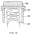
- a conventional cathode for an electron tube includes a heater coil 101, a cylindrical sleeve 102 with the built-in heater coil 101, a metal substrate 103, containing nickel as a main component and a trace of reducing elements such as magnesium, at one opening of the sleeve 102, and an emissive material layer 104 adhered onto the substrate 103.
- a material that includes as a main component an alkaline earth metal oxide containing barium is used as an oxide cathode. A phenomenon is found that the emission current of such a cathode gradually decreases after long operation of several thousand hours due to the deterioration of emissive materials.
- an object of the present invention to provide a long-life cathode - particularly, a cathode for an electron tube that has little decrease in emission current after long operation and has a sufficient life even if the current density is further increased in a CRT, and to provide a long-life and economical cathode for an electron tube.
- the present invention provides a cathode for an electron tube in which an emissive material, having particles that include the oxide of an alkaline earth metal as a main component and at least one element selected from the group consisting of titanium, zirconium and hafnium, is adhered onto a metal substrate including nickel as a main component.
- the present invention also provides a cathode for an electron tube in which an emissive material, including the oxide of an alkaline earth metal as a main component and at least one element selected from the group consisting of vanadium, niobium and tantalum, is adhered onto a metal substrate including nickel as a main component.
- an emissive material including the oxide of an alkaline earth metal as a main component and at least one element selected from the group consisting of vanadium, niobium and tantalum, is adhered onto a metal substrate including nickel as a main component.
- a long-life cathode for an electron tube is provided.
- the properties of the emissive material improve, especially in reducing the deterioration of the emission current under high current density.
- an economical and long-life cathode with long emission current stability is provided by adding, along with the oxide of an alkaline earth metal, at least one element selected from the group consisting of vanadium, niobium and tantalum to the emissive material of the cathode.
- the present invention provides a method for manufacturing a cathode for an electron tube, including the step of thermally decomposing carbonate containing at least one element selected from the group consisting of titanium, zirconium, hafnium, vanadium, niobium and tantalum and an alkaline earth metal so as to adhere an emissive material, containing the oxide of the alkaline earth metal as a main component and the above-noted element, onto a metal substrate including nickel as a main component.
- the element such as titanium is evenly provided in each particle of the alkaline earth metal oxide, so that a cathode with even emissive properties and stability is provided.
- a first cathode of the present invention has an emissive material, including particles containing the oxide of an alkaline earth metal as a main component and at least one element selected from the group consisting of titanium, zirconium and hafnium, adhered onto a metal substrate including nickel as a main component.
- the total content of at least one element selected from the group consisting of titanium, zirconium and hafnium is from 0.001 wt. % to 1 wt. %, or more preferably from 0.001 wt. % to 0.1 wt. %, relative to the total weight of the emissive material. Therefore, the emissive properties of the cathode improve.
- the cathode can be used under high current density.
- the emissive material further includes particles of an alkaline earth metal oxide.
- the cathode has improved emissive properties, and can be used under high current density. More specifically, it is preferable that the emissive material includes the mixture of the particles containing the oxide of an alkaline earth metal as a main component and at least one element selected from the group consisting of titanium, zirconium and hafnium and the particles of an alkaline earth metal oxide. In this case, it is preferable that the particles containing the oxide of an alkaline earth metal as a main component and at least one element selected from the group consisting of titanium, zirconium and hafnium are included at 20 wt. % to 80 wt. % relative to the total weight of the emissive material. As a result, the emissive properties of the cathode further improve.
- a second cathode of the present invention has an emissive material including particles, containing the oxide of an alkaline earth metal as a main component and at least one element selected from the group consisting of vanadium, niobium and tantalum, adhered onto a metal substrate including nickel as a main component.
- the content of the above-mentioned element is from 0.001 wt. % to 5 wt. % relative to the total weight of the emissive material when the element is included as a metal.
- the emission current is stabilized for a long period, and the life of the cathode increases.
- the content of the element is from 0.002 wt. % to 6 wt. % relative to the total weight of the emissive material when the element is included as an oxide. Therefore, as mentioned above, the emission current would be stabilized for a long period, and an economical and long-life cathode is provided.
- the oxide is in the form of particles having an average particle diameter of 10 ⁇ m or less, so that the emission current further stabilizes for a long period.
- a first method of the present invention includes the step of thermally decomposing carbonate, containing at least one element selected from the group consisting of titanium, zirconium and hafnium and an alkaline earth metal, so as to adhere the particles of an emissive material, containing the oxide of the alkaline earth metal as a main component and the element mentioned above, onto a metal substrate including nickel as a main component.
- the element such as titanium is evenly provided in each particle of the alkaline earth metal oxide, so that a cathode with even emissive properties and stability is provided.
- the method further includes the step of coprecipitating, from a solution including the nitrate of at least one element selected from the group consisting of titanium and zirconium and the nitrate of an alkaline earth metal, the above-mentioned element and alkaline earth metal as carbonate.
- the above-mentioned element and alkaline earth metal are coprecipitated as carbonate by mixing the solution containing the nitrate mentioned above with a solution including a carbonate ion (more preferably, a solution containing at least one salt selected from the group consisting of the carbonate of an alkaline metal, the hydrogencarbonate of an alkaline metal, ammonium carbonate and ammonium hydrogencarbonate).
- a second method of the present invention includes the step of thermally decomposing carbonate, containing at least one element selected from the group consisting of vanadium, niobium and tantalum and an alkaline earth metal, so as to adhere an emissive material containing the oxide of the alkaline earth metal as a main component and the element mentioned above onto a metal substrate including nickel as a main component.
- the element such as vanadium is evenly provided in each particle of the alkaline earth metal oxide, so that a cathode with even emissive properties and stability is provided.
- the method further includes the step of coprecipitating, from a solution including the nitrate of at least one element selected from the group consisting of vanadium and niobium and the nitrate of an alkaline earth element, the above-noted element and alkaline earth element as carbonate.
- the above-mentioned element and alkaline earth element are coprecipitated as carbonate by mixing the solution containing the nitrate mentioned above with a solution containing a carbonate ion (more preferably, a solution containing at least one salt selected from the group consisting of the carbonate of an alkaline metal, the hydrogencarbonate of an alkaline metal, ammonium carbonate and ammonium hydrogencarbonate).
- the method further includes the step of coprecipitating tantalum and an alkaline earth metal as carbonate by mixing a solution containing the carbonate of the alkaline earth metal and tantalum with a solution containing the nitrate of the alkaline earth metal.
- the residual impurities in the emissive material would be reduced in this method, so that the life of the cathode increases.
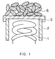
- FIG. 1 shows a schematic structure of one embodiment of a cathode of the present invention.
- the cathode includes a heater coil 1, a cylindrical sleeve 2 with the built-in heater coil 1, a metal substrate 3 that contains nickel as a main component and a trace of reducing elements such as magnesium positioned at one opening of the sleeve 2, and an emissive material layer, including particles 5 containing barium and an alkaline earth metal oxide as a main component, adhered onto the substrate 3.
- Each particle includes at least one element selected from the group consisting of titanium, zirconium and hafnium.
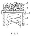
- FIG. 2 shows a schematic structure of another embodiment of a cathode of the present invention.
- an emissive material layer includes particles 5, containing an alkaline earth metal oxide as a main component and titanium and the like, and particles 6 of alkaline earth metal oxides.
- the emissive material layers shown in FIG. 1 and FIG. 2 that are adhered onto a substrate as the particles 5 and 6 are different from the conventional emissive material layer 4 shown in FIG. 14.
- FIG. 3 shows a schematic structure of another embodiment of a cathode of the present invention.
- the cathode shown in FIG. 3 includes a heater coil 1, a cylindrical sleeve 2 with the built-in heater coil 1, a metal substrate 3 that contains nickel as a main component and a trace of reducing elements such as magnesium positioned at one opening of the sleeve 2, and an emissive material layer including an alkaline earth metal oxide 7 containing barium and at least one metal selected from the group consisting of vanadium, niobium and tantalum ( or an oxide thereof ) 8, adhered onto the substrate 3.
- Zirconium nitrate was dissolved in a solution of alkaline earth metal nitrate, including barium nitrate and strontium nitrate, so as to have a content of zirconium atoms of 0.02 mole % (mole ratio relative to the entire amount of alkaline earth metal), thus preparing a mixed solution.
- a solution of sodium carbonate was added to this mixed solution, thereby preparing ternary (barium/strontium/zirconium) coprecipitated carbonate particles in which each particle includes zirconium atoms at an average of 0.02 mole %.
- zirconium (IV) dinitrate oxide may be used.
- the carbonate or the hydrogencarbonate of an alkaline metal, ammonium carbonate, or ammonium hydrogencarbonate may be used instead of sodium carbonate.
- the ternary coprecipitated carbonate particles were adhered onto a cathode substrate in a thickness of about 50 ⁇ m, and were thermally decomposed in a vacuum at 930°C.
- a cathode having the same structure as in FIG. 1 was provided that had an emissive material layer including ternary (barium/strontium/zirconium) oxide particles (with 0.015 wt. % average content of zirconium).
- titanium nitrate or hafnium chloride was used instead of zirconium nitrate so as to provide a cathode having the same structure as in FIG. 1 and having an emissive material layer including barium/strontium/titanium or barium/strontium/hafnium oxide particles with 0.015 wt. % average content of titanium atoms or hafnium atoms.
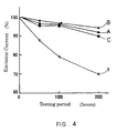
- the cathode prepared as described above was used in a CRT for displays, and an accelerated life test was carried out for 2,000 hours while the current density of the CRT was set at 2.0A/cm 2 at the beginning of the operation.
- FIG. 4 shows the change in emission current with time in the accelerated life test.
- Line A in the figure shows the result in the case of the cathode having an emissive material layer including barium/strontium/titanium coprecipitated oxide particles;
- line B indicates the result in the case of the cathode having an emissive material layer including barium/strontium/zirconium coprecipitated oxide particles;
- line C shows the result in the case of the cathode having an emissive material layer including barium/strontium/hafnium coprecipitated oxide particles;
- line (a) indicates the result in the case of a conventional cathode having an emissive material layer containing the particles of an alkaline earth metal oxide.
- the decrease in emission current of the cathode by the accelerated life test is smaller than that of the conventional cathode when titanium, zirconium or hafnium is included in each particle of the alkaline earth metal oxide, thus improving the life of the cathode.
- the particles of an alkaline earth metal oxide in which titanium or zirconium is coprecipitated are used for an emissive material layer, the decrease in emission current would be reduced significantly. This is because nitrate is used as a material in preparing carbonate particles, so that much less residual impurities are found in the emissive material layer than in the case of using the chlorides as a starting material. (The impurities are chlorine when using chloride as a starting material.)
- the effect of increasing the life of a cathode is found when the content of titanium, zirconium or hafnium is from 0.001 wt. % to 1 wt. % , more preferably from 0.001 wt. % to 0.1 wt. %, relative to the total weight of the emissive material layer.
- binary (barium/strontium) alkaline earth metals were used for oxide particles in this example, the same effects were also found in using ternary (barium/strontium/calcium) alkaline earth metals. This is also true in the following examples.
- Zirconium nitrate was dissolved in a solution of alkaline earth metal nitrate, including barium nitrate and strontium nitrate, at 0.04 mole % relative to the entire alkaline earth metal (at 0.03 wt. % relative to the particles of the alkaline earth metal oxide), thus preparing a mixed solution.
- a solution of sodium carbonate was added to this mixed solution, thereby precipitating ternary (barium/strontium/zirconium) carbonate particles in which zirconium atoms are contained at an average of 0.04 mole %.
- a solution of sodium carbonate was added to a mixed solution of barium nitrate and strontium nitrate for precipitation, thus providing particles of binary (barium/strontium) carbonate.
- the ternary carbonate particles and the binary carbonate particles were mixed at a 1:1 weight ratio so as to prepare a mixed material of carbonate particles containing zirconium and carbonate particles containing no zirconium.
- the mixed material was adhered onto a cathode substrate in a thickness of about 50 ⁇ m, and was thermally decomposed in a vacuum at 930°C.
- a cathode was provided that had an emissive material layer including the mixed material of ternary (barium/strontium/zirconium) oxide particles 5 and binary (barium/strontium) oxide particles 6 as shown in FIG. 2.
- the cathode prepared as described above was used in a CRT for displays, and an accelerated life test was carried out for 2,000 hours while the current density of the CRT was set at 2.7A/cm 2 at the beginning of the operation.
- FIG. 6 shows the change in emission current with time in the accelerated life test.
- line D shows the result in the case of the cathode that has an emissive material layer including the mixed material of the ternary (barium/strontium/zirconium) oxide particles and the binary (barium/strontium) oxide particles; and
- line (b) shows the result in the case of the cathode that has an emissive material layer including only the mixed material of the ternary (barium/strontium/zirconium) oxide particles.
- the effect of improving the life of a cathode was found when the particles of the alkaline earth metal oxide containing titanium, zirconium or hafnium were contained at 20 wt. % to 80 wt. % relative to the total weight of an emissive material layer.
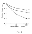
- the cathode prepared as described above was used in a CRT for displays, and an accelerated life test was carried out for 2,000 hours while the current density of the CRT was set at 2.0A/cm 2 at the beginning of the operation.
- FIG. 7 shows the change in emission current with time in the accelerated life test.
- line E shows the result in the case of the cathode in which vanadium was added to the emissive material layer
- line F indicates the result in the case of the cathode in which vanadium oxide was added to the emissive material layer
- line (a) shows the result in the case of a conventional cathode in which an emissive material layer is made only of an alkaline earth metal oxide.
- vanadium and vanadium oxide can be obtained easily in the industry, and are economical.
- an economical and long-life cathode is provided.
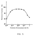
- the effects of reducing the deterioration of emission current were obtained effectively when the contents of vanadium and vanadium oxide were 0.001 wt. % to 5 wt. % and 0.002 wt. % to 6 wt. % respectively, relative to the entire weight of the emissive material layer.
- the best effects were obtained particularly when the contents of vanadium and vanadium oxide were about 1.1 wt. % and about 1.3 wt. % respectively relative to the total weight of the emissive material layer.
- a mixed material was prepared by adding niobium oxide, instead of vanadium oxide, at 1 wt. % relative to barium/strontium carbonate (1.3 wt. % relative to an emissive material layer).
- the mixed material was adhered onto a cathode substrate in a thickness of about 50 ⁇ m, and was then thermally decomposed at 930°C in a vacuum.
- a cathode was provided that had an emissive material layer including barium/strontium oxide and niobium oxide.
- the cathode prepared as described above was used in a CRT for displays, and an accelerated life test was carried out for 2,000 hours while current density was set at 2.0A/cm 2 at the beginning of the operation. Regarding the deterioration of the emission current, the same results as in the case of adding vanadium oxide were obtained, thus increasing the life of the cathode.
- the cathode of this example also has the properties of limiting the heat contraction of the emissive material layer. As a result, the change in cut-off voltage was reduced.
- the above-noted cut-off voltage indicates the cathode voltage for cutting off emission current, and the value of the voltage changes due to the heat contraction of an emissive material layer.
- FIG. 9 shows the change in cut-off voltage with time in the accelerated life test.
- line G indicates the result in the case of the cathode of this example in which niobium oxide was added to the emissive material layer; and line (a) indicates the result of a conventional cathode without niobium oxide.
- the change in cut-off voltage by the accelerated life test becomes small when niobium oxide is added to the emissive material layer.
- niobium oxide was added to the emissive material layer, but the same results are obtained when niobium is used instead.
- vanadium niobium and niobium oxide easily can be obtained in the industry and are also economical.
- an economical cathode is provided.
- the contents of niobium and niobium oxide relative to the emissive material layer are 0.001 wt. % to 5 wt. % and 0.002 wt. % to 6 wt. % respectively, so that the effect of reducing the deterioration of emission current is obtained.
- a mixed material was prepared by adding tantalum oxide, instead of vanadium oxide, at 1 wt. % relative to barium/strontium carbonate (1.3 wt. % relative to an emissive material layer).
- the mixed material was adhered onto a cathode substrate in a thickness of about 50 ⁇ m, and was then thermally decomposed at 930°C in a vacuum.
- a cathode was provided that had an emissive material layer including barium/strontium oxide and tantalum oxide.
- the cathode prepared as described above was used in a CRT for displays, and an accelerated life test was carried out for 2,000 hours while the current density was set at 2.7A/cm 2 at the beginning of the operation.
- FIG. 10 shows the change in emission current with time in the accelerated life test.
- line H indicates the result of the cathode of this example in which tantalum oxide was added to the emissive material layer; and line (c) shows the result of a conventional cathode.
- the cathode has a much smaller decrease in emission voltage in the accelerated life test than the conventional cathode when tantalum oxide was added to the emissive material layer, so that the life of the cathode improves.
- tantalum oxide was added to the emissive material layer, but the same results are obtained when tantalum is used instead.
- Tantalum and tantalum oxide easily can be obtained in the industry and are also economical.
- an economical cathode is provided. Similar to the contents of vanadium and vanadium oxide mentioned in Example 3, the contents of tantalum and tantalum oxide relative to the emissive material layer are 0.001 wt. % to 5 wt. % and 0.002 wt. % to 6 wt. % respectively, so that the effect of limiting the decrease in emission current is obtained.
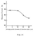
- FIG. 11 shows the relationship between the average particle diameter of tantalum oxide and emission current (%) after 2,000 hours of testing, wherein the emission current is 100% at the beginning of the accelerated life test. According to the figure, the decrease in emission current was prevented effectively when the average particle diameter of tantalum oxide was 10 ⁇ m or less.
- the average particle diameter is preferably 10 ⁇ m or less.
- a solution of sodium carbonate was added, thus preparing the ternary coprecipitated carbonate of barium/strontium /vanadium containing vanadium at 0.01 mole %.
- the carbonate was adhered onto a cathode substrate in a thickness of about 50 ⁇ m, and was thermally decomposed in a vacuum at 930 °C.
- a cathode was provided that had an emissive material layer, made of barium/strontium/vanadium oxide containing vanadium at 0.004 wt. %.
- FIG. 12 shows the change in emission current with time in the accelerated life test.
- line I indicates the result in the case of the cathode having the emissive material layer in which vanadium was coprecipitated.
- the decrease in emission current in the accelerated life test becomes small when vanadium is coprecipitated in the emissive material layer, so that the life of the cathode improves.
- niobium nitrate was used instead of vanadium nitrate to form an emissive material layer of a barium/strontium/niobium coprecipitated oxide.
- the effect of reducing the deterioration of emission current was obtained effectively in this example when vanadium and niobium were contained in a range of 0.001 wt. % to 1 wt. % relative to the emissive material layer.
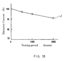
- tantalum was dissolved at 0.01 mole % relative to the whole nitrate solution. Then, a solution of sodium carbonate was added, thus preparing a coprecipitated material of tantalum and barium/strontium carbonate containing tantalum at 0.01 mole %.
- the coprecipitated material was adhered onto a cathode substrate at a thickness of about 50 ⁇ m, and was thermally decomposed in a vacuum at 930°C.
- a cathode was provided that had an emissive material layer made of barium/strontium oxide containing tantalum at 0.014 wt. %.
- the cathode prepared as described above was used in a CRT for displays, and an accelerated life test was carried out for 2,000 hours while the current density of the CRT was set at 2.7A/cm 2 at the beginning of the operation.
- FIG. 13 shows the change in the emission current with time in the accelerated life test.
- line J indicates the test result of the cathode having the emissive material layer in which tantalum was coprecipitated.
- the decrease in emission current by the accelerated life test becomes small when tantalum is coprecipitated in the emissive material layer, so that the life of the cathode increases.
- the effect of reducing the deterioration of the emission current was obtained effectively in this example when the content of tantalum was from 0.001 wt. % to 1 wt. % relative to the emissive material layer.
Landscapes
- Solid Thermionic Cathode (AREA)
Applications Claiming Priority (6)
| Application Number | Priority Date | Filing Date | Title |
|---|---|---|---|
| JP30002596A JPH10144202A (ja) | 1996-11-12 | 1996-11-12 | 電子管陰極およびその製造方法 |
| JP300024/96 | 1996-11-12 | ||
| JP300025/96 | 1996-11-12 | ||
| JP30002496 | 1996-11-12 | ||
| JP30002596 | 1996-11-12 | ||
| JP30002496A JPH10144201A (ja) | 1996-11-12 | 1996-11-12 | 電子管陰極およびその製造方法 |
Publications (2)
| Publication Number | Publication Date |
|---|---|
| EP0841676A1 true EP0841676A1 (de) | 1998-05-13 |
| EP0841676B1 EP0841676B1 (de) | 2003-03-05 |
Family
ID=26562183
Family Applications (1)
| Application Number | Title | Priority Date | Filing Date |
|---|---|---|---|
| EP97119574A Expired - Lifetime EP0841676B1 (de) | 1996-11-12 | 1997-11-08 | Kathode für eine Elektronenröhre und Herstellungsverfahren |
Country Status (8)
| Country | Link |
|---|---|
| US (1) | US5925976A (de) |
| EP (1) | EP0841676B1 (de) |
| KR (1) | KR100319227B1 (de) |
| CN (1) | CN1123031C (de) |
| CA (1) | CA2220537C (de) |
| DE (1) | DE69719452T2 (de) |
| MY (1) | MY119054A (de) |
| NO (1) | NO975206L (de) |
Cited By (2)
| Publication number | Priority date | Publication date | Assignee | Title |
|---|---|---|---|---|
| EP1282147A3 (de) * | 2001-08-01 | 2004-05-06 | Matsushita Electric Industrial Co., Ltd. | Elektronenröhrenanordnung mit langer Lebensdauer, Elektronenröhrenkathode und Verfahren zur Herstellung |
| WO2004049371A3 (en) * | 2002-11-23 | 2004-10-14 | Philips Intellectual Property | Vacuum tube with oxide cathode |
Families Citing this family (6)
| Publication number | Priority date | Publication date | Assignee | Title |
|---|---|---|---|---|
| KR19990043956A (ko) * | 1997-11-30 | 1999-06-25 | 김영남 | 브라운관용 전극재료 |
| JP2001229814A (ja) * | 2000-02-21 | 2001-08-24 | Matsushita Electric Ind Co Ltd | 酸化物陰極の製造方法、およびこの酸化物陰極を備えた陰極線管 |
| FR2810446A1 (fr) * | 2000-06-14 | 2001-12-21 | Thomson Tubes & Displays | Cathodes a oxyde amelioree et son procede de fabrication |
| US20020195919A1 (en) * | 2001-06-22 | 2002-12-26 | Choi Jong-Seo | Cathode for electron tube and method of preparing the cathode |
| CN100521037C (zh) * | 2003-01-17 | 2009-07-29 | 浜松光子学株式会社 | 碱金属发生剂 |
| CN101866795B (zh) * | 2010-04-26 | 2012-01-25 | 南京三乐电子信息产业集团有限公司 | 一种镍网阴极的制备方法 |
Citations (6)
| Publication number | Priority date | Publication date | Assignee | Title |
|---|---|---|---|---|
| GB663981A (en) * | 1948-07-30 | 1951-01-02 | Sylvania Electric Prod | Method of preparing electron-emissive coating materials |
| GB700313A (en) * | 1951-01-25 | 1953-11-25 | Crompton Parkinson Ltd | Improvements in or relating to electrodes for electrical discharge apparatus |
| JPS63257153A (ja) * | 1987-04-14 | 1988-10-25 | Mitsubishi Electric Corp | 電子管用陰極 |
| EP0330355A2 (de) * | 1988-02-23 | 1989-08-30 | Mitsubishi Denki Kabushiki Kaisha | Kathode für eine Elektronenröhre |
| JPH01315926A (ja) * | 1988-06-15 | 1989-12-20 | Mitsubishi Electric Corp | 電子管用陰極 |
| EP0373701A1 (de) * | 1988-12-13 | 1990-06-20 | Koninklijke Philips Electronics N.V. | Oxidkathode |
Family Cites Families (8)
| Publication number | Priority date | Publication date | Assignee | Title |
|---|---|---|---|---|
| GB182817A (en) * | 1921-07-11 | 1923-08-09 | Drahtlose Telegraphie Gmbh | Improvements in the cathodes of electric discharge tubes |
| US1870951A (en) * | 1928-07-11 | 1932-08-09 | Westinghouse Lamp Co | Electron emission material |
| BE440192A (de) * | 1940-02-21 | |||
| FR1029729A (fr) * | 1950-01-26 | 1953-06-05 | Rca Corp | Matière émettrice d'électrons |
| US2703790A (en) * | 1952-08-28 | 1955-03-08 | Raytheon Mfg Co | Electron emissive materials |
| CA1270890A (en) * | 1985-07-19 | 1990-06-26 | Keiji Watanabe | Cathode for electron tube |
| JPS6222347A (ja) * | 1985-07-19 | 1987-01-30 | Mitsubishi Electric Corp | 電子管用陰極 |
| NL9002291A (nl) * | 1990-10-22 | 1992-05-18 | Philips Nv | Oxydekathode. |
-
1997
- 1997-11-07 US US08/966,113 patent/US5925976A/en not_active Expired - Fee Related
- 1997-11-08 EP EP97119574A patent/EP0841676B1/de not_active Expired - Lifetime
- 1997-11-08 DE DE69719452T patent/DE69719452T2/de not_active Expired - Fee Related
- 1997-11-10 CA CA002220537A patent/CA2220537C/en not_active Expired - Fee Related
- 1997-11-11 KR KR1019970059294A patent/KR100319227B1/ko not_active Expired - Fee Related
- 1997-11-11 MY MYPI97005351A patent/MY119054A/en unknown
- 1997-11-12 NO NO975206A patent/NO975206L/no unknown
- 1997-11-12 CN CN97114352A patent/CN1123031C/zh not_active Expired - Fee Related
Patent Citations (6)
| Publication number | Priority date | Publication date | Assignee | Title |
|---|---|---|---|---|
| GB663981A (en) * | 1948-07-30 | 1951-01-02 | Sylvania Electric Prod | Method of preparing electron-emissive coating materials |
| GB700313A (en) * | 1951-01-25 | 1953-11-25 | Crompton Parkinson Ltd | Improvements in or relating to electrodes for electrical discharge apparatus |
| JPS63257153A (ja) * | 1987-04-14 | 1988-10-25 | Mitsubishi Electric Corp | 電子管用陰極 |
| EP0330355A2 (de) * | 1988-02-23 | 1989-08-30 | Mitsubishi Denki Kabushiki Kaisha | Kathode für eine Elektronenröhre |
| JPH01315926A (ja) * | 1988-06-15 | 1989-12-20 | Mitsubishi Electric Corp | 電子管用陰極 |
| EP0373701A1 (de) * | 1988-12-13 | 1990-06-20 | Koninklijke Philips Electronics N.V. | Oxidkathode |
Non-Patent Citations (2)
| Title |
|---|
| PATENT ABSTRACTS OF JAPAN vol. 013, no. 074 (E - 717) 20 February 1989 (1989-02-20) * |
| PATENT ABSTRACTS OF JAPAN vol. 014, no. 120 (E - 0899) 6 March 1990 (1990-03-06) * |
Cited By (3)
| Publication number | Priority date | Publication date | Assignee | Title |
|---|---|---|---|---|
| EP1282147A3 (de) * | 2001-08-01 | 2004-05-06 | Matsushita Electric Industrial Co., Ltd. | Elektronenröhrenanordnung mit langer Lebensdauer, Elektronenröhrenkathode und Verfahren zur Herstellung |
| US6882093B2 (en) | 2001-08-01 | 2005-04-19 | Matsushita Electric Industrial Co., Ltd. | Long-life electron tube device, electron tube cathode, and manufacturing method for the electron tube device |
| WO2004049371A3 (en) * | 2002-11-23 | 2004-10-14 | Philips Intellectual Property | Vacuum tube with oxide cathode |
Also Published As
| Publication number | Publication date |
|---|---|
| DE69719452D1 (de) | 2003-04-10 |
| KR100319227B1 (ko) | 2002-02-19 |
| MY119054A (en) | 2005-03-31 |
| KR19980042289A (ko) | 1998-08-17 |
| NO975206L (no) | 1998-05-13 |
| CA2220537C (en) | 2005-10-18 |
| EP0841676B1 (de) | 2003-03-05 |
| CN1123031C (zh) | 2003-10-01 |
| NO975206D0 (no) | 1997-11-12 |
| US5925976A (en) | 1999-07-20 |
| CA2220537A1 (en) | 1998-05-12 |
| DE69719452T2 (de) | 2003-10-02 |
| CN1189680A (zh) | 1998-08-05 |
Similar Documents
| Publication | Publication Date | Title |
|---|---|---|
| EP0841676B1 (de) | Kathode für eine Elektronenröhre und Herstellungsverfahren | |
| KR0143555B1 (ko) | 산화물 음극 | |
| EP0373701B1 (de) | Oxidkathode | |
| EP0300568B1 (de) | Oxydkathode | |
| KR100200661B1 (ko) | 전자관용 음극 | |
| EP1232512B1 (de) | Kathodenstrahlröhre mit kompositkathode | |
| US5982083A (en) | Cathode for electron tube | |
| JP2928155B2 (ja) | 電子管用陰極 | |
| JP5226921B2 (ja) | ドープ酸化物陰極を具えた陰極線管 | |
| EP0847071B1 (de) | Kathode für eine elektronenröhre | |
| EP0639848B1 (de) | Oxydkathode für Elektronenröhre | |
| JP2000067810A (ja) | 放電灯用電極および放電灯 | |
| US20060076871A1 (en) | Vacuum tube with oxide cathode | |
| JPH06223776A (ja) | 蛍光ランプ用電極 | |
| JPH10144202A (ja) | 電子管陰極およびその製造方法 | |
| JPH10144201A (ja) | 電子管陰極およびその製造方法 | |
| JPH08329845A (ja) | ガス放電パネル | |
| KR100625959B1 (ko) | 전자관용 음극의 제조방법 | |
| WO1997035943A1 (en) | Phosphor materials | |
| JPH1064404A (ja) | 陰極およびその製造方法 | |
| JPH03289022A (ja) | 酸化物陰極 | |
| KR20000014067A (ko) | 전자관용 음극 |
Legal Events
| Date | Code | Title | Description |
|---|---|---|---|
| PUAI | Public reference made under article 153(3) epc to a published international application that has entered the european phase |
Free format text: ORIGINAL CODE: 0009012 |
|
| AK | Designated contracting states |
Kind code of ref document: A1 Designated state(s): DE FR GB IT NL SE |
|
| AX | Request for extension of the european patent |
Free format text: AL;LT;LV;MK;RO;SI |
|
| 17P | Request for examination filed |
Effective date: 19980703 |
|
| 17Q | First examination report despatched |
Effective date: 19980916 |
|
| AKX | Designation fees paid |
Free format text: DE FR GB IT NL SE |
|
| RBV | Designated contracting states (corrected) |
Designated state(s): DE FR GB IT NL SE |
|
| RAP1 | Party data changed (applicant data changed or rights of an application transferred) |
Owner name: MATSUSHITA ELECTRIC INDUSTRIAL CO., LTD. |
|
| GRAH | Despatch of communication of intention to grant a patent |
Free format text: ORIGINAL CODE: EPIDOS IGRA |
|
| GRAH | Despatch of communication of intention to grant a patent |
Free format text: ORIGINAL CODE: EPIDOS IGRA |
|
| GRAA | (expected) grant |
Free format text: ORIGINAL CODE: 0009210 |
|
| AK | Designated contracting states |
Designated state(s): DE FR GB IT NL SE |
|
| REG | Reference to a national code |
Ref country code: GB Ref legal event code: FG4D |
|
| REF | Corresponds to: |
Ref document number: 69719452 Country of ref document: DE Date of ref document: 20030410 Kind code of ref document: P |
|
| REG | Reference to a national code |
Ref country code: SE Ref legal event code: TRGR |
|
| PLBE | No opposition filed within time limit |
Free format text: ORIGINAL CODE: 0009261 |
|
| STAA | Information on the status of an ep patent application or granted ep patent |
Free format text: STATUS: NO OPPOSITION FILED WITHIN TIME LIMIT |
|
| 26N | No opposition filed |
Effective date: 20031208 |
|
| PGFP | Annual fee paid to national office [announced via postgrant information from national office to epo] |
Ref country code: DE Payment date: 20061102 Year of fee payment: 10 |
|
| PGFP | Annual fee paid to national office [announced via postgrant information from national office to epo] |
Ref country code: SE Payment date: 20061106 Year of fee payment: 10 |
|
| PGFP | Annual fee paid to national office [announced via postgrant information from national office to epo] |
Ref country code: GB Payment date: 20061108 Year of fee payment: 10 Ref country code: FR Payment date: 20061108 Year of fee payment: 10 |
|
| PGFP | Annual fee paid to national office [announced via postgrant information from national office to epo] |
Ref country code: NL Payment date: 20061115 Year of fee payment: 10 |
|
| PGFP | Annual fee paid to national office [announced via postgrant information from national office to epo] |
Ref country code: IT Payment date: 20061130 Year of fee payment: 10 |
|
| EUG | Se: european patent has lapsed | ||
| GBPC | Gb: european patent ceased through non-payment of renewal fee |
Effective date: 20071108 |
|
| NLV4 | Nl: lapsed or anulled due to non-payment of the annual fee |
Effective date: 20080601 |
|
| PG25 | Lapsed in a contracting state [announced via postgrant information from national office to epo] |
Ref country code: SE Free format text: LAPSE BECAUSE OF NON-PAYMENT OF DUE FEES Effective date: 20071109 Ref country code: NL Free format text: LAPSE BECAUSE OF NON-PAYMENT OF DUE FEES Effective date: 20080601 Ref country code: DE Free format text: LAPSE BECAUSE OF NON-PAYMENT OF DUE FEES Effective date: 20080603 |
|
| REG | Reference to a national code |
Ref country code: FR Ref legal event code: ST Effective date: 20080930 |
|
| PG25 | Lapsed in a contracting state [announced via postgrant information from national office to epo] |
Ref country code: GB Free format text: LAPSE BECAUSE OF NON-PAYMENT OF DUE FEES Effective date: 20071108 |
|
| PG25 | Lapsed in a contracting state [announced via postgrant information from national office to epo] |
Ref country code: FR Free format text: LAPSE BECAUSE OF NON-PAYMENT OF DUE FEES Effective date: 20071130 |
|
| PG25 | Lapsed in a contracting state [announced via postgrant information from national office to epo] |
Ref country code: IT Free format text: LAPSE BECAUSE OF NON-PAYMENT OF DUE FEES Effective date: 20071108 |