EP0886193A2 - Bilderzeugungsgerät und Bestimmung des angeschlossenen Geräts - Google Patents
Bilderzeugungsgerät und Bestimmung des angeschlossenen Geräts Download PDFInfo
- Publication number
- EP0886193A2 EP0886193A2 EP98109474A EP98109474A EP0886193A2 EP 0886193 A2 EP0886193 A2 EP 0886193A2 EP 98109474 A EP98109474 A EP 98109474A EP 98109474 A EP98109474 A EP 98109474A EP 0886193 A2 EP0886193 A2 EP 0886193A2
- Authority
- EP
- European Patent Office
- Prior art keywords
- signal
- voltage
- output
- adjustment
- terminal
- Prior art date
- Legal status (The legal status is an assumption and is not a legal conclusion. Google has not performed a legal analysis and makes no representation as to the accuracy of the status listed.)
- Granted
Links
- 238000000034 method Methods 0.000 title claims description 18
- 238000001514 detection method Methods 0.000 claims abstract description 44
- 108090000237 interleukin-24 Proteins 0.000 claims description 3
- 101000661816 Homo sapiens Suppression of tumorigenicity 18 protein Proteins 0.000 claims description 2
- 230000005856 abnormality Effects 0.000 claims 2
- 101000661807 Homo sapiens Suppressor of tumorigenicity 14 protein Proteins 0.000 claims 1
- 101000585359 Homo sapiens Suppressor of tumorigenicity 20 protein Proteins 0.000 claims 1
- 102100029860 Suppressor of tumorigenicity 20 protein Human genes 0.000 claims 1
- 238000012546 transfer Methods 0.000 description 13
- 230000002159 abnormal effect Effects 0.000 description 12
- 239000004065 semiconductor Substances 0.000 description 6
- 238000006243 chemical reaction Methods 0.000 description 5
- 238000012545 processing Methods 0.000 description 5
- 238000003705 background correction Methods 0.000 description 4
- 210000000078 claw Anatomy 0.000 description 3
- 238000004891 communication Methods 0.000 description 3
- 238000010438 heat treatment Methods 0.000 description 3
- 230000003287 optical effect Effects 0.000 description 3
- 238000010586 diagram Methods 0.000 description 2
- 230000006870 function Effects 0.000 description 2
- 230000002452 interceptive effect Effects 0.000 description 2
- 238000012423 maintenance Methods 0.000 description 2
- 102100036848 C-C motif chemokine 20 Human genes 0.000 description 1
- 101000713099 Homo sapiens C-C motif chemokine 20 Proteins 0.000 description 1
- 230000002411 adverse Effects 0.000 description 1
- 238000012790 confirmation Methods 0.000 description 1
- 238000013144 data compression Methods 0.000 description 1
- 230000007547 defect Effects 0.000 description 1
- 238000011161 development Methods 0.000 description 1
- 230000005611 electricity Effects 0.000 description 1
- 239000011521 glass Substances 0.000 description 1
- 239000004973 liquid crystal related substance Substances 0.000 description 1
- 238000004519 manufacturing process Methods 0.000 description 1
- 238000004886 process control Methods 0.000 description 1
- 238000000926 separation method Methods 0.000 description 1
- 230000003068 static effect Effects 0.000 description 1
- 238000011144 upstream manufacturing Methods 0.000 description 1
- 230000000007 visual effect Effects 0.000 description 1
Images




Classifications
-
- G—PHYSICS
- G03—PHOTOGRAPHY; CINEMATOGRAPHY; ANALOGOUS TECHNIQUES USING WAVES OTHER THAN OPTICAL WAVES; ELECTROGRAPHY; HOLOGRAPHY
- G03G—ELECTROGRAPHY; ELECTROPHOTOGRAPHY; MAGNETOGRAPHY
- G03G15/00—Apparatus for electrographic processes using a charge pattern
- G03G15/80—Details relating to power supplies, circuits boards, electrical connections
-
- G—PHYSICS
- G03—PHOTOGRAPHY; CINEMATOGRAPHY; ANALOGOUS TECHNIQUES USING WAVES OTHER THAN OPTICAL WAVES; ELECTROGRAPHY; HOLOGRAPHY
- G03G—ELECTROGRAPHY; ELECTROPHOTOGRAPHY; MAGNETOGRAPHY
- G03G15/00—Apparatus for electrographic processes using a charge pattern
- G03G15/06—Apparatus for electrographic processes using a charge pattern for developing
- G03G15/065—Arrangements for controlling the potential of the developing electrode
Definitions
- This invention relates to an image forming apparatus which requires high voltage output adjustment, and also to a connected-object detecting method for detecting before the high voltage output adjustment whether or not an adjustment tool is connected to the apparatus instead of a development unit.
- Electrophotography image forming apparatuses are equipped with high voltage transformers.
- a high voltage obtained from the high voltage transformer is applied to a charger, a developing device, etc. incorporated therein.
- To adjust the high voltage output of the transformer it is considered necessary to dismount a developing unit including the developing device. If the high voltage output of the transformer is adjusted with the developing unit mounted, it is possible that (1) a charger voltage will be output and a developing bias will not be output, thereby causing a developer to fall, or that (2) the developing bias will be output and the charger voltage will not be output, thereby causing toner to scatter.
- the apparatus may well be much adversely affected.
- the high voltage output adjustment must be performed with the developing unit dismounted and a dedicated adjustment tool mounted instead.
- the mounting of the dedicated adjustment tool is confirmed mainly visually.
- an image forming apparatus for forming, on a image carrier, an electrostatic latent image corresponding to a document image, and then providing an image based on the electrostatic latent image formed on the image carrier, comprising: first output means having a first output section for outputting a first signal corresponding to the temperature of the image carrier; a first unit having the first output means; second output means having a second output section for outputting a second signal with a level differing from the first signal; a second unit having the second output means; input means having a temperature signal input section which is to be connected to one of the first and second output sections for inputting a signal output from the one of the first and second output sections; and detection means for detecting the one of the first and second output sections which is connected to the temperature signal input section, and also detecting the temperature of the image carrier.
- a to-be-connected object detecting method for use in an image forming apparatus for forming, on a image carrier, an electrostatic latent image corresponding to a document image, and then providing an image based on the electrostatic latent image formed on the image carrier, comprising: the first step of detecting a signal output from a temperature input section connected to one of a first output section for outputting a first signal corresponding to the temperature of the image carrier, and a second output section for outputting a second signal with a different level from the first signal; and the second step of detecting the one of the first and second output sections which is connected to the temperature signal input section and the temperature of the image carrier on the basis of the detection result at the first step.
- FIG. 1 is a schematic sectional view, showing the internal structure of an image forming apparatus according to the embodiment of the invention.
- an openable/closable auto document feeder (ADF) 7 is provided on the upper surface of the main body 10 of the image forming apparatus 2.
- the ADF 7 also serves as a document cover, and is disposed to feed documents set thereon to a document table one by one.
- a paper feed cassette 57 and a large capacity paper feed cassette 55 are detachably attached to a right side portion of the main body 10.
- the paper feed cassette 57 can contain a small number of paper sheets, while the large capacity paper feed cassette 55 can contain a great number of paper sheets.
- a manual feed tray 56 for feeding paper sheets manually is provided on the paper feed cassette 57.
- Paper feed cassettes 52 - 54 are detachably attached to a lower portion of the main body 10. Paper sheets of the same size are contained in each of the cassettes 52 - 54 lengthways or sideways. One of these cassettes is voluntarily selected. A finisher 80 for receiving printed sheets is attached to a side portion of the main body 10.
- the main body 10 includes a scanner section 4 and a printer section 6.
- a document table 12 of transparent glass on which a document D is placed is provided on the upper surface of the main body 10.
- the ADF 7 is attached to the table 12 such that the table can be opened and closed, and also serves to urge the document D against the table 12.
- the ADF 7 includes a document tray 8, an empty sensor 9, a pick-up roller 14, a paper feed roller 15, a pair of aligning rollers 16 and a conveyance belt 18.
- the document tray 8 receives documents to be copied.
- the empty sensor 9 detects whether or not any document is set in the document tray 8.
- the pick-up roller 14 picks up, one by one, the documents set in the document tray 8.
- the documents are picked up from the lowest one, i.e. from the last page.
- the paper feed roller 15 conveys each document picked by the pick-up roller 14, to the document table 12.
- the pair of aligning rollers 16 align the front end of the document with the document table 12.
- the conveyance belt 18 conveys the document placed on the document table 12. The document is reversed or discharged to the ADF 7 as a result of conveyance by the conveyance belt 18.
- the ADF 7 further includes a reverse roller 20, a non-reverse sensor 21, a flapper 22 and a paper discharge roller 23, which are provided at an end opposite to the end at which the aligning rollers 16 are provided, with the conveyance belt 18 interposed therebetween.
- the document D whose image information has been read by the scanner section 4 is conveyed from the document table 12 by the conveyance belt 18, and discharged, via the reverse roller 20, the flapper 21 and the paper discharge roller 22, onto a document discharge section 24 which constitutes an upper surface portion of the ADF 7.
- the flapper 22 is switched such that the reverse roller 20 reverses the document D conveyed by the conveyance belt 18, and the conveyance belt 18 again conveys the document to a predetermined portion of the document table 12.
- the scanner section 4 provided in the main body 10 includes an exposure lamp 25 and a first mirror 26.
- the exposure lamp 25 is a light source for illuminating the document D placed on the document table 12.
- the first mirror 26 deflects, in a predetermined direction, light reflected from the document D.
- the exposure lamp 25 and the first mirror 26 are attached to a first carriage 27 provided below the document table 12.
- the first carriage 27 is disposed such that it can move parallel to the document table 12. Further, the first carriage 27 is reciprocated below the document table 12 by a driving force transmitted from a driving motor (not shown) via a toothed belt (not shown).
- a second carriage 28 is provided below the document table 12 such that it can move parallel to the document table 12.
- the second carriage 28 has second and third mirrors 30 and 31 attached thereto such that they are situated at right angles to each other.
- the second and third mirrors 30 and 31 successively deflect light reflected from the document D and deflected by the first mirror 26.
- the second carriage 28 is moved in accordance with the movement of the first carriage 27 by means of the toothed belt which drives the first carriage 27. More specifically, the second carriage 28 is moved parallel to the document table 12 at half the speed of the first carriage 27.
- An image forming lens 32 and a CCD sensor 34 are provided below the document table 12.
- the image forming lens 32 is located on a plane which includes the path of light deflected by the third mirror 31 of the second carriage 28.
- the image forming lens 32 converges, at a desired magnifying power, light reflected from the third mirror 31.
- the CCD sensor 34 subjects, to photoelectric conversion, the light converged by the image forming lens 32, thereby outputting an electric signal corresponding to the read document D.
- the printer section 6 includes a laser exposure unit 40 and a photosensitive drum 44.
- the laser exposure unit 40 as means for forming an electrostatic latent image is fixed on a support frame (not shown) incorporated in the main body 10.
- the laser exposure unit 40 includes a semiconductor laser 41, a polygonal mirror 36, a polygonal motor 37 and an optical system 42.
- the polygonal mirror 36 continuously deflects laser light emitted from the semiconductor laser 41.
- the polygonal motor 37 rotates the polygonal mirror 36 at a predetermined rotational speed.
- the optical system 42 deflects laser light from the polygonal mirror 36, to the photosensitive drum 44.
- the On/Off state of the semiconductor laser 41 is controlled on the basis of image information read from the document D by the scanner section 4.
- the laser light emitted from the semiconductor laser 41 is directed to the photosensitive drum 44 via the polygonal mirror 36 and the optical system 42.
- the laser light directed to the photosensitive drum 44 scans the periphery thereof, thereby forming an electrostatic latent image thereon.
- the rotatable photosensitive drum 44 as an image carrier is located at a substantially center portion of the main body 10.
- the periphery of the drum 44 is exposed to the laser light emitted from the semiconductor laser unit 40, thereby forming a desired electrostatic latent image.
- a charger 45, a developing unit 46, a separating charger 47 are provided integral around the photosensitive drum 44.
- the charger 45 charges the periphery of the drum with predetermined static electricity.
- the developing unit 46 supplies toner as a developer to the electrostatic latent image formed on the periphery of the drum 44, thereby developing an image of a desired density.
- a transfer charger 48, a separating claw 49, a cleaner unit 50 and a deelectrifying lamp 51 are also provided around the photosensitive drum 44 in this order.
- the transfer charger 48 transfers a toner image formed on the photosensitive drum 44, to a paper sheet P.
- the separating claw 49 separates the paper sheet P from the photosensitive drum 44.
- the cleaner unit 50 cleans toner remaining on the drum 44.
- the deelectrifying lamp 51 deelectrifies the periphery of the drum 44.
- the developing unit 46 has an outward appearance as shown in FIG. 2.
- the developing unit 46 is attachable to the main body 10 and detachable therefrom, and includes a connector C2 and a thermister 46a.
- the connector C2 is to be connected to the connector of a printer CPU which will be described later.
- the thermister 46a detects the surface temperature of the photosensitive drum 44, and outputs a signal indicative of the temperature of the drum 44.
- an input voltage (+5V) input to the circuit including the thermister 46a is divided by a resistor R1, the thermister 46a, a resistor R2 and a resistor R3, and then input to a printer CPU 110. Accordingly, when the temperature in the vicinity of the thermister 46a varies, the resistance of the thermister 46a varies, and hence the voltage input to the printer CPU 110 varies. From the varied voltage, the printer CPU 110 detects the temperature in the vicinity of the thermister 46a.
- the main body 10 contains, in its lower portion, detachable upper, middle and lower cassettes 52, 53 and 54 stacked on each other. Paper sheets of different sizes are contained in the cassettes.
- the large capacity cassette 55 is detachably attached close to side portions of the cassettes 52 - 54.
- the large capacity cassette 55 contains a great number of paper sheets of a size with a high frequency of use, for example, paper sheets of A4 size.
- the paper feed cassette 57 which also serves as a manual feed tray 56 is mounted above the large capacity cassette 55.
- a conveyance path 58 is formed in the main body 10.
- the conveyance path 58 extends from each cassette through a transfer section located between the photosensitive drum 44 and the transfer charger 48.
- a fixing unit 60 with a fixing lamp 129 is provided at the terminal of the conveyance path 58.
- a discharge port 61 is formed in that side wall portion of the main body 10 which is opposed to the fixing unit 60.
- the finisher 80 is mounted in the discharge port 61.
- a pick-up roller 63 for picking up the paper sheets P one by one is provided in the vicinity of each of the upper, middle and lower cassettes 52, 53, 54, the paper feed cassette 57 and the large capacity paper feed cassette 55.
- Multiple paper feed roller pairs 64 are provided along the conveyance path 58 for conveying the paper sheets P picked by the pick-up rollers 63 through the conveyance path 58.
- a pair of resist rollers 65 are provided across the conveyance path 58 upstream of the photosensitive drum 44.
- the resist rollers 65 correct the inclination, if any, of each paper sheet P conveyed on the path 58, align the front end of the sheet with that of a toner image on the photosensitive drum 44, and convey the sheet to the transfer section at the same speed as the circumferential speed of the photosensitive drum 44.
- a sensor 66 for sensing the arrival of each paper sheet P is provided across that portion of the conveyance path 58 which is located downstream of the resist rollers 65, i.e. on the paper feed roller 64 side.
- the paper sheets P picked by each pick-up roller 63 one by one are conveyed from the paper feed rollers 64 to the resist rollers 65. After having their front ends adjusted by the resist rollers 65, the paper sheets P are conveyed to the transfer section.
- an image formed on the photosensitive drum 44 i.e. a toner image
- the paper sheet P with the toner image is separated from the photosensitive drum 44 by the separating charger 47 and the separating claw 49, and conveyed to the fixing unit 60 by a conveyance belt 67 which constitutes part of the conveyance path 58.
- the toner image is melted and fixed on the sheet P by the fixing unit 60.
- the paper sheet P is discharged to the finisher 80 through the discharge port 61 by means of paper feed rollers 68 and discharge rollers 69.
- An automatic reversing unit 70 is provided below the conveyance path 58.
- the reversing unit 70 reverses the paper sheet P having passed the fixed unit 60, and feeds the reversed paper sheet P back to the resist rollers 65.
- the reversing unit 70 includes a reversing path 72, a pick-up roller 73, a conveyance path 74, and paper feed rollers 75.
- the reversing path 72 reverses the paper sheet P having passed the fixing unit 60, and guides it to a temporarily collecting section 71.
- the temporarily collecting section 71 temporarily collects paper sheets guided by the reversing path 72.
- the pick-up roller 73 picks up, one by one, the sheets collected in the collecting section 71.
- the paper feed rollers 75 forward to the conveyance path 74 the paper sheet P picked by the pick-up roller 73.
- the conveyance path 74 guides, to the paper feed rollers 65, the paper sheet P forwarded by the paper feed rollers 75.
- a distribution gate 76 is interposed between the conveyance path 58 and the reversing path 72 for selectively distributing the paper sheets P to the discharge port 61 or the reversing path 72.
- the paper sheet is guided to the reversing path 72 after it is passed through the fixing unit 60. Subsequently, the paper sheet is collected in the temporarily collecting section 71, and then guided to the resist rollers 65 through the conveyance path 74 by means of the pick-up roller 73 and the paper feed rollers 75. After the paper sheet is adjusted in position by the resist rollers 65, it is conveyed again to the transfer section, where a toner image is copied on the reverse surface of the paper sheet.
- the finisher 80 can receive a predetermined number of paper sheets P at a time, and if necessary, a predetermined number of stapled paper sheets P.
- the image forming apparatus comprises a main control section 90, the operation panel 200, the scanner section 4 and the printer section 6.
- the main control section 90 has a main CPU 91.
- the operation panel 200, the scanner section 4 and the printer section 6 have a panel CPU 132, a scanner CPU 100, and a printer CPU 110, respectively.
- the printer CPU 110 functions as various detection means.
- the main CPU 91 performs interactive communication with the printer CPU 110 via a common RAM 95.
- the main CPU 91 sends an instruction to the printer CPU 110.
- the printer CPU 110 supplies the main CPU 91 with a signal indicative of the status of the CPU 110.
- the printer CPU 110 and the scanner CPU 100 perform serial communication.
- the printer CPU 110 sends an instruction to the scanner CPU 100.
- the scanner CPU 100 supplies the printer CPU 110 with a signal indicative of the status of the CPU 100.
- the main CPU 91 is also connected to the panel CPU 132.
- the main CPU 91 receives various instructions from the panel CPU 132 and sends various instructions to the CPU 132.
- the main CPU 91 for controlling the entire main control section 90 includes a ROM 92, a RAM 93, a NVM 94, a common RAM 95, an image processing section 96, a page memory control section 97, and a page memory 98.
- the ROM 92 stores control programs, etc.
- the RAM 93 temporarily stores various data items.
- the common RAM 95 is used to enable interactive communication between the main CPU 91 and the printer CPU 110.
- the image processing section 96 performs various image processes such as image data compression, expansion, etc.
- the page memory control section 97 writes image data into the page memory 98 and reads image data therefrom.
- the page memory 98 stores compressed image data in units of one page, and has a memory area capable of storing image data of plural pages.
- the scanner CPU 100 controls the entire scanner section 4.
- the scanner CPU 100 includes a ROM 101, a RAM 102, a CCD driver 103, a scan motor driver 104 and an image correcting section 105.
- the ROM 101 stores control programs, etc.
- the RAM 102 temporarily stores various data items.
- the CCD driver 103 drives the CCD sensor 34.
- the scan motor driver 104 controls the rotation of a motor for moving the exposure lamp 25, the mirrors 26, 27, 28, etc.
- the image correcting section 105 has an A/D conversion circuit, a shading correction circuit, and a line memory, which are not shown.
- the A/D conversion circuit converts an analog signal from the CCD sensor 34 to a digital signal.
- the shading correction circuit corrects variations in threshold level due to variations in the output of the CCD sensor 34. Variations in the output of the CCD sensor 34 may be caused by, for example, changes in ambient temperature.
- the line memory temporarily stores a digital signal output from the shading correction circuit and subjected to shading correction.
- the printer CPU 110 controls the entire printer section 6, and includes a ROM 111, a RAM 112, a laser driver 113, a polygonal motor driver 114, a paper conveyance section 115, a high voltage transformer control section 118, a deelectrifying lamp control section 126, a fixing lamp control section 128, and an image processing control section 130.
- the ROM 111 stores control programs, etc.
- the RAM 112 temporarily stores various data items.
- the laser driver 113 performs on/off control of the semiconductor laser 41.
- the polygonal motor driver 114 controls the rotation of the polygonal motor 37.
- the paper conveyance section 115 controls the conveyance of paper sheets P through the conveyance path 58.
- the high voltage transformer control section 118 is connected to high voltage transformers 119 - 123 to control them.
- the deelectrifying lamp control section 126 controls the deelectrifying lamp 51.
- the fixing lamp control section 128 controls the fixing lamp 129.
- the developing process control section 130 controls a developing process which includes charging, developing, transfer and separation steps to be performed using the charger 45, the developing unit 46, the separating charger 47 and the transfer charger 48.
- the high voltage transformers 119 - 123 are connected to the charger 45, the transfer charger 48, the separating charger 47, the deelectrifying charger 125, and the developing unit 46, respectively. Further, the high voltage transformer control section 118 is connected to a charging-grid control section 116, which is connected to a charging grid 117.
- the image processing section 96, the page memory 98, the image correcting section 105 and the laser driver 113 are connected to each other by an image data bus 120.
- the panel CPU 132 controls the entire operation panel section 200, and includes a display section 134, an input section 136 and a buzzer 138.
- the display section 134 has a touch panel.
- the input section 136 inputs instructions concerning various operations.
- the buzzer replaces a signal with a warning sound.
- the operation panel section 200 as adjusting and reporting means is provided on an upper front surface of the main body 10.
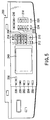
- the operation panel section 200 includes a copy designation key 202, a FAX designation key 204 and a printer designation key 206.
- the copy designation key 202, the FAX designation key 204 and the printer designation key 206 is used to set, in the main body, a copy mode, a FAX mode and a printer mode, respectively.
- the operation panel section 200 includes a ten key 208, a copy key 210, a clear/stop key 212, an all clear key 214 and a copy magnification setting key 216.
- the ten key 208 receives a numerical input indicative of, for example, the number of copies in the copy mode.
- the copy key 210 is used to start copying.
- the clear/stop key 212 is used to correct the number of copies, to stop the copying operation, etc.
- the all clear key 214 is used to clear the setting items designated using various keys.
- the copy magnification setting key 216 receives setting of a copy magnification (reading magnification).
- the operation panel section 200 further includes a sheet size key 218, an automatic sheet selecting key 220, a document size key 222, an automatic magnification selecting key 224, an operation guide key 226, a pre-heating key 228 and an interruption key 230.
- the paper size key 218 is used to designate the size of paper sheets to be printed.
- the automatic paper selecting key 220 is used to designate an automatic paper selecting mode for automatically determining the size of a paper sheet to be printed. In the automatic paper selecting mode, the size of a document placed on the document table is detected, thereby automatically selecting a paper size corresponding to the document size.
- the document size key 222 is used to instruct the size of a document to be copied.
- the automatic magnification selecting key 224 is used to designate an automatic magnification selecting mode.
- the copy magnification is automatically set on the basis of the size of the paper sheet received through the paper size key 218, and the size of the document placed on the document table.
- the operation guide key 226 is used to display various data items.
- the various data items include set conditions, a set mode, and an operation procedure, etc.
- the pre-heating key 228 is used to designate a pre-heating mode in the main body of the apparatus.
- the interruption key 230 is used to perform job interruption.
- a display panel 240 consisting of a touch panel type liquid crystal display unit is provided at a substantially center portion of the operation panel section 200.
- the display panel 240 displays, using characters and figures, the state of the apparatus, the operation procedure and various messages to the user.
- a maintenance mode to be executed through the operation panel 200 will be described.
- the maintenance mode is executed.
- the display panel 240 displays a high voltage output adjusting key for instructing execution of high voltage output adjustment.
- the panel CPU 132 receives an instruction to perform high voltage output adjustment.
- the panel CPU 132 instructs the main CPU 91 to do high voltage output adjustment.
- the main CPU 91 instructs the printer CPU 110 to do high voltage output adjustment.
- the printer CPU 110 determines whether or not the high voltage output adjustment can be performed. If the printer CPU 110 determines that the adjustment can be done, it instructs the high voltage transformer control section 118 to perform the high voltage output adjustment. The high voltage transformer control section 118, in turn, performs high voltage output adjustment of the high voltage transformers 119 - 123. If, on the other hand, the printer CPU 110 determines that the high voltage output adjustment is impossible, it informs the main CPU 91 that the high voltage output adjustment is impossible. The main CPU 91, in turn, informs the panel CPU 132 that the high voltage output adjustment is impossible. Then, the panel CPU 132 displays, on the display section 134, a predetermined message such as "high voltage output adjustment is impossible (confirm whether or not an adjustment tool is mounted)".
- the image forming apparatus of the invention is disposed to permit high voltage adjustment only when it is detected, from the level of a signal output from the thermister 46a, that the adjustment tool 300 is connected. This operation will be described in more detail.
- the surface potential of the photosensitive drum 44 varies in accordance with a change in ambient temperature.
- the surface potential change will cause a change in the density of an image.
- the surface potential change may well cause blotty and/or faint characters, which means that the apparatus cannot execute its function.
- the surface temperature of the photosensitive drum 44 is detected, and the charging grid voltage is adjusted in accordance with the detected temperature.
- the surface temperature of the photosensitive drum 44 is detected by the thermister 46a as a temperature detecting element.
- the thermister 46a is attached to the developing unit 46 located near the drum 44 so as not to flaw the surface of the drum 44.
- the thermister 46a has its resistance varied with a change in temperature. Accordingly a voltage signal output from the thermister 46a varies in accordance with a change in temperature.
- the voltage signal from the thermister 46a is input to the printer CPU 110, where it is converted to a digital signal via an analog/digital conversion port (which can represent analog signals by digital values of 256 stages).
- the ROM 111 stores a data table shown in FIG. 7.
- the printer CPU 110 reads data from the data table in the ROM 111, and calculates the temperature of a place in the vicinity of the thermister 46a on the basis of the converted digital signal and the data table.
- the printer CPU 110 further calculates an appropriate charging grid voltage on the basis of the data table and the calculated temperature.
- Data on the calculated charging grid voltage is sent from the printer CPU 110 to the charging grid control section 116 via the high voltage transformer control section 118.
- the charging grid control section 116 controls a voltage to be applied to the charging grid 117, on the basis of the calculated charging grid voltage.
- the voltage applied to the printer CPU 110 via the thermister 46a is +3.8V - +1.2V, and is expressed by a digital value 195 - 56 after its digital conversion.
- the voltage applied to the printer CPU 110 is +5V, and its digital value is 256.
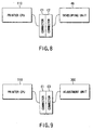
- the connector C1 of the printer CPU 110, the connector C2 of the developing unit 46 and the connector C3 of the adjustment tool unit 300 will be described. Further, signals transmitted between the printer CPU 110 and the developing unit 46 and between the printer CPU 110 and the adjustment tool unit 300 will be described.
- the printer CPU 110 and the developing unit 46 are connected to each other by their connectors C1 and C2.
- the printer CPU 110 and the adjustment tool unit 300 are connected to each other by their connectors C1 and C3.
- the connector C1 of the printer CPU 110 is connected to the connector C2 of the developing unit 46 when high voltage output adjustment is performed, it is necessary to disconnect the connector C2 from the connector C1 and detach the developing unit 46 from the apparatus main body 10. Then, it is necessary to attach the adjustment tool unit 300 to the main body 10 and connect the connector C3 to the connector C1.
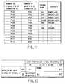
- the connector C1 has twelve female pins P101 - P112.
- the connector C2 has twelve male pins P201 - P212.
- the connector C3 has twelve male pins P301 - P312.
- the male pins P201 - P212 of the connector C2 are disposed to be connected to the female pins P101 - P112 of the connector C1, respectively.
- the male pins P301 - P312 of the connector C3 are disposed to be connected to the female pins P101 - P112 of the connector C1, respectively.
- the connector C1 is disposed to be connected to only one of the connectors C2 and C3.
- a developing unit signal (5V) is applied from the male pin P205 of the connector C2 to the female pin P105 of the connector C1, and then to the printer CPU 110.
- the printer CPU 110 detects that the connector C2 is connected to the connector C1, i.e. that the developing unit 46 is connected to the apparatus main body 10.
- a drum temperature signal (0 - 5V) is applied from the male pin P207 of the connector C2 to the female pin P107 of the connector C1, and then to the printer CPU 110. From the voltage level of the drum temperature signal, the printer CPU 110 detects the surface temperature of the photo-sensitive drum 44 and the object connected to the female pin P107.
- the object to be connected to the female pin P107 is one of the male pin P207 (the developing unit 46) and the male pin P307 (the adjustment tool unit 300).
- the printer CPU 110 detects from the developing unit signal that the developing unit 46 is connected. If at this time, the printer CPU 110 receives a drum temperature signal of 0V or 5V, it detects that the temperature of the photosensitive drum 44 is abnormal (*1). When detecting the abnormal temperature of the photosensitive drum 44, the printer CPU 110 informs the main CPU 91 of it. The main CPU 91, in turn, informs the panel CPU 132 of the fact. Then, the panel CPU 132 controls the display section 134 to display a predetermined message such as "the drum temperature is abnormal".
- the printer CPU 110 detects from the developing unit signal that the developing unit 46 is connected. If at this time, the printer CPU 110 receives a drum temperature signal of +1.2V - +3.8V, it detects that the drum operates normally. From the voltage level of the drum temperature signal, the printer CPU 110 detects the temperature of a place in the vicinity of the thermister 46a and an appropriate charging grid voltage. More specifically, the printer CPU 110 reads the data table (FIG. 7) stored in the ROM 111, and detects the temperature of the place in the vicinity of the thermister 46a and the appropriate charging grid voltage on the basis of the data table and the voltage level of the drum temperature signal.
- the printer CPU 110 reads the data table (FIG. 7) stored in the ROM 111, and detects the temperature of the place in the vicinity of the thermister 46a and the appropriate charging grid voltage on the basis of the data table and the voltage level of the drum temperature signal.
- the printer CPU 110 supplies data on the appropriate charging grid voltage to the charging grid control section 116 via the high voltage transformer control section 118.
- the charging grid control section 116 controls the charging grid voltage of the charging grid 117 on the basis of the data.
- a signal A (0V) is applied, instead of the developing unit signal, from the male pin P305 of the connector C3 to the female pin P105 of the connector C1, and then to the printer CPU 110.
- the level of the signal A differs from that of the developing unit signal.
- the printer CPU 110 detects that the connector C2 is not connected to the connector C1, i.e. that the developing unit 46 is not connected to the apparatus main body 10.
- a signal B (0 - 5V) is applied, instead of the drum temperature signal, from the male pin P307 of the connector C2 to the female pin P107 of the connector C1, and then to the printer CPU 110. From the voltage level of the signal B, the printer CPU 110 detects the object connected to the female pin P107.
- the object to be connected to the female pin P107 is one of the male pin P207 (the developing unit 46) and the male pin P307 (the adjustment tool unit 300).
- the printer CPU 110 detects from the signal A that the developing unit 46 is not connected. If at this time, the printer CPU 110 receives a signal of 0V, it detects that the connector C3 (the adjustment tool unit 300) is connected to the connector C1. When the printer CPU 110 detects that the connectors C1 and C3 are connected to each other, it permits high voltage output adjustment.
- the printer CPU 110 detects from the signal A that the developing unit 46 is not connected. If at this time, the printer CPU 110 receives a signal B of +1.2V - +3.8V, it detects that the connector C2 (the developing unit 46) is connected to the connector C1 (*2). In this case, the printer CPU 110 does not permit high voltage output adjustment. In other words, the printer CPU 110 does not accept the instruction to perform the high voltage adjustment input through the display section 134 of the display panel 200.
- the printer CPU 110 detects from the signal A that the developing unit 46 is not connected. If at this time, the printer CPU 110 receives a signal B of 5V, it detects that the temperature of the photosensitive drum 44 is abnormal (*3). When detecting the abnormal temperature of the photosensitive drum 44, the printer CPU 110 informs the main CPU 91 of it. The main CPU 91, in turn, informs the panel CPU 132 of the fact. Then, the panel CPU 132 controls the display section 134 to display a predetermined message such as "the drum temperature is abnormal".
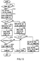
- the image forming apparatus is turned on (ST10, Yes), and various initial settings are performed (ST12). Subsequently, the main CPU 91 instructs the printer CPU 110 to check various states. Upon receiving the instruction from the main CPU 91, the printer CPU 110 checks various states. For example, the printer CPU 110 checks the voltage level of a signal (a developing unit signal S1) input to the pin P105 of the connector C1 (ST14). If the voltage level of the signal (the developing unit signal S1) input to the pin P105 of the connector C1 is 5V (ST16, Yes), the printer CPU 110 detects that the developing unit signal S1 is input to the pin P105 of the connector C1, i.e. that the developing unit 46 is connected to the apparatus main body 10 (ST18).
- a signal a developing unit signal S1 input to the pin P105 of the connector C1
- the printer CPU 110 also checks the voltage level of a signal (a drum surface temperature signal S2) input to the pin P107 of the connector C1 (ST14). If the voltage level of the signal (the drum surface temperature signal S2) input to the pin P107 of the connector C1 is not less than +1.2V and also not more than +3.8V (ST22, Yes), the printer CPU 110 detects that the surface temperature of the drum is normal. When it is detected that the developing unit is connected and also that the drum surface temperature is normal, the printer CPU 110 informs the main CPU 91 of this. Then, the main CPU 91 controls the apparatus main body 10 to start to warm up (ST24), thereby setting the main body 10 in a stand-by state (ST26).
- a signal a drum surface temperature signal S2 input to the pin P107 of the connector C1
- the printer CPU 110 detects that the surface temperature of the drum is abnormal. When it is detected that the developing unit is connected and also that the drum surface temperature is abnormal, the printer CPU 110 informs the main CPU 91 that the drum surface temperature is abnormal. Then, the main CPU 91 informs the panel CPU 132 of it. The panel CPU 132, in turn, controls the display section 134 to display an error message such as "the drum temperature is abnormal" (ST34).
- the printer CPU 110 detects that the developing unit signal S1 is not input to the pin P105 of the connector C1, i.e. that the developing unit 46 is not connected to the apparatus main body 10.
- the printer CPU 110 also checks the voltage level of a signal input to the pin P107 of the connector C1 (ST30). If the voltage level of the signal input to the pin P107 of the connector C1 is not 0 (ST32, No), the printer CPU 110 detects that the surface temperature of the drum is abnormal. At this time, the printer CPU 110 informs the main CPU 91 that the drum surface temperature is abnormal.
- the main CPU 91 informs the panel CPU 132 of it.
- the panel CPU 132 controls the display section 134 to display an error message (ST34).
- the printer CPU 110 detects that the adjustment tool unit 300 is connected (ST36), and permits high voltage adjustment (ST38).
- the invention provides an image forming apparatus which can be manufactured at low cost and is free from the risk of such a mistake as non-attachment of the adjustment tool unit to be attached to the apparatus when the high voltage output is adjusted.
- the invention provides a method for detecting an object to be connected, which method can reduce the manufacturing cost of an image forming apparatus to which the method is applied. The method can also prevent such a mistake as non-attachment of the adjustment tool unit to be attached to the apparatus when high voltage output adjustment is performed.
Landscapes
- Physics & Mathematics (AREA)
- General Physics & Mathematics (AREA)
- Control Or Security For Electrophotography (AREA)
Applications Claiming Priority (3)
| Application Number | Priority Date | Filing Date | Title |
|---|---|---|---|
| JP141897/97 | 1997-05-30 | ||
| JP9141897A JPH10333508A (ja) | 1997-05-30 | 1997-05-30 | 画像形成装置 |
| JP14189797 | 1997-05-30 |
Publications (3)
| Publication Number | Publication Date |
|---|---|
| EP0886193A2 true EP0886193A2 (de) | 1998-12-23 |
| EP0886193A3 EP0886193A3 (de) | 1999-01-13 |
| EP0886193B1 EP0886193B1 (de) | 2001-11-21 |
Family
ID=15302717
Family Applications (1)
| Application Number | Title | Priority Date | Filing Date |
|---|---|---|---|
| EP98109474A Expired - Lifetime EP0886193B1 (de) | 1997-05-30 | 1998-05-25 | Bilderzeugungsgerät und Bestimmung des angeschlossenen Geräts |
Country Status (5)
| Country | Link |
|---|---|
| US (1) | US5953552A (de) |
| EP (1) | EP0886193B1 (de) |
| JP (1) | JPH10333508A (de) |
| CN (1) | CN1122880C (de) |
| DE (1) | DE69803245T2 (de) |
Families Citing this family (9)
| Publication number | Priority date | Publication date | Assignee | Title |
|---|---|---|---|---|
| JP3453503B2 (ja) * | 1997-12-02 | 2003-10-06 | キヤノン株式会社 | 多色画像形成装置 |
| JP2002139966A (ja) * | 2000-10-31 | 2002-05-17 | Fuji Xerox Co Ltd | 画像形成システム |
| US20060000710A1 (en) * | 2004-06-30 | 2006-01-05 | Klaus Peter Weidenhaupt | Fluid handling methods |
| JP2006301012A (ja) * | 2005-04-15 | 2006-11-02 | Canon Inc | 温度検出装置、温度制御装置、画像形成装置、制御方法、及びプログラム |
| KR100611307B1 (ko) * | 2005-06-20 | 2006-08-10 | 삼성전자주식회사 | 현상유닛 및 화상형성장치 |
| US20090168573A1 (en) * | 2007-12-31 | 2009-07-02 | Ming Zhang | Adaptive memory array voltage adjustment |
| JP5725759B2 (ja) * | 2010-08-18 | 2015-05-27 | キヤノン株式会社 | 画像形成装置 |
| WO2015027152A1 (en) * | 2013-08-22 | 2015-02-26 | Thorlabs, Inc. | Beam expander using two power-adjustable lenses |
| JP6799794B2 (ja) * | 2017-12-08 | 2020-12-16 | ブラザー工業株式会社 | クレードル制御プログラム及びクレードル装置 |
Family Cites Families (11)
| Publication number | Priority date | Publication date | Assignee | Title |
|---|---|---|---|---|
| DE3644355A1 (de) * | 1985-12-24 | 1987-07-30 | Toshiba Kawasaki Kk | Bilderzeugungsvorrichtung |
| US4994852A (en) * | 1987-08-18 | 1991-02-19 | Minolta Camera Kabushiki Kaisha | Image forming apparatus having a malfunction detection device and power shutdown therefor |
| JP2786657B2 (ja) * | 1989-03-23 | 1998-08-13 | 株式会社東芝 | 画像形成装置 |
| JP3009179B2 (ja) * | 1990-04-16 | 2000-02-14 | 株式会社日立製作所 | 静電記録装置及び静電潜像測定装置 |
| JPH04140766A (ja) * | 1990-10-01 | 1992-05-14 | Mita Ind Co Ltd | 画像形成装置 |
| JP3010180B2 (ja) * | 1990-11-29 | 2000-02-14 | 株式会社東芝 | 画像形成装置 |
| JP2971139B2 (ja) * | 1990-12-19 | 1999-11-02 | 株式会社リコー | 画像形成装置 |
| US5319426A (en) * | 1992-12-02 | 1994-06-07 | Eastman Kodak Company | Image forming apparatus having improved fusing consistency |
| US5585825A (en) * | 1994-11-25 | 1996-12-17 | Xerox Corporation | Ink jet printer having temperature sensor for replaceable printheads |
| US5699091A (en) * | 1994-12-22 | 1997-12-16 | Hewlett-Packard Company | Replaceable part with integral memory for usage, calibration and other data |
| JPH09325642A (ja) * | 1996-06-06 | 1997-12-16 | Canon Inc | 定着器の誤実装検出法および画像形成装置 |
-
1997
- 1997-05-30 JP JP9141897A patent/JPH10333508A/ja active Pending
-
1998
- 1998-05-25 DE DE69803245T patent/DE69803245T2/de not_active Expired - Fee Related
- 1998-05-25 EP EP98109474A patent/EP0886193B1/de not_active Expired - Lifetime
- 1998-05-28 US US09/084,913 patent/US5953552A/en not_active Expired - Fee Related
- 1998-05-29 CN CN98109359A patent/CN1122880C/zh not_active Expired - Fee Related
Also Published As
| Publication number | Publication date |
|---|---|
| JPH10333508A (ja) | 1998-12-18 |
| DE69803245T2 (de) | 2002-06-27 |
| DE69803245D1 (de) | 2002-02-21 |
| CN1201168A (zh) | 1998-12-09 |
| CN1122880C (zh) | 2003-10-01 |
| EP0886193B1 (de) | 2001-11-21 |
| EP0886193A3 (de) | 1999-01-13 |
| US5953552A (en) | 1999-09-14 |
Similar Documents
| Publication | Publication Date | Title |
|---|---|---|
| EP0994397B1 (de) | Bilderzeugungsgerät | |
| JPH0769654B2 (ja) | 電子写真複写・フアクシミリ送信複合機 | |
| JP2003122227A (ja) | 画像形成装置及びその制御方法 | |
| US5953552A (en) | Image forming apparatus and method for detecting connected object | |
| JPH06329298A (ja) | 画像形成装置の管理システム | |
| US20040022548A1 (en) | Image forming apparatus and error resetting method | |
| JP3105149B2 (ja) | 画像形成装置 | |
| JPH1097112A (ja) | 画像形成装置及び画像形成方法 | |
| US6430377B1 (en) | Image forming apparatus and method with sheet removal after jam detection | |
| JP3255574B2 (ja) | 画像形成装置及び画像形成方法 | |
| US12348690B2 (en) | Image reading apparatus and image reading method | |
| JP2005266690A (ja) | 画像形成装置 | |
| JP3598770B2 (ja) | 画像処理装置 | |
| JPH07336522A (ja) | 複写装置 | |
| JPH11242300A (ja) | 複写装置 | |
| JPH086329A (ja) | 画像形成装置 | |
| JP3645188B2 (ja) | 画像形成装置 | |
| JP3174584B2 (ja) | 画像入出力装置 | |
| JP3806244B2 (ja) | 画像形成装置 | |
| JPH05281817A (ja) | 画像形成装置 | |
| JP3472640B2 (ja) | 複写機 | |
| JP4511776B2 (ja) | 画像形成装置および画像形成方法 | |
| JP3480862B2 (ja) | 画像形成装置および画像形成方法 | |
| JPH0237367A (ja) | 画像形成装置 | |
| JPH07199740A (ja) | 画像形成装置 |
Legal Events
| Date | Code | Title | Description |
|---|---|---|---|
| PUAI | Public reference made under article 153(3) epc to a published international application that has entered the european phase |
Free format text: ORIGINAL CODE: 0009012 |
|
| PUAL | Search report despatched |
Free format text: ORIGINAL CODE: 0009013 |
|
| 17P | Request for examination filed |
Effective date: 19980525 |
|
| AK | Designated contracting states |
Kind code of ref document: A2 Designated state(s): DE FR GB |
|
| AX | Request for extension of the european patent |
Free format text: AL;LT;LV;MK;RO;SI |
|
| AK | Designated contracting states |
Kind code of ref document: A3 Designated state(s): AT BE CH CY DE DK ES FI FR GB GR IE IT LI LU MC NL PT SE |
|
| AX | Request for extension of the european patent |
Free format text: AL;LT;LV;MK;RO;SI |
|
| 17Q | First examination report despatched |
Effective date: 19990226 |
|
| AKX | Designation fees paid |
Free format text: DE FR GB |
|
| GRAG | Despatch of communication of intention to grant |
Free format text: ORIGINAL CODE: EPIDOS AGRA |
|
| GRAG | Despatch of communication of intention to grant |
Free format text: ORIGINAL CODE: EPIDOS AGRA |
|
| GRAH | Despatch of communication of intention to grant a patent |
Free format text: ORIGINAL CODE: EPIDOS IGRA |
|
| GRAH | Despatch of communication of intention to grant a patent |
Free format text: ORIGINAL CODE: EPIDOS IGRA |
|
| GRAA | (expected) grant |
Free format text: ORIGINAL CODE: 0009210 |
|
| AK | Designated contracting states |
Kind code of ref document: B1 Designated state(s): DE FR GB |
|
| PG25 | Lapsed in a contracting state [announced via postgrant information from national office to epo] |
Ref country code: FR Free format text: LAPSE BECAUSE OF FAILURE TO SUBMIT A TRANSLATION OF THE DESCRIPTION OR TO PAY THE FEE WITHIN THE PRESCRIBED TIME-LIMIT Effective date: 20011121 |
|
| REG | Reference to a national code |
Ref country code: GB Ref legal event code: IF02 |
|
| REF | Corresponds to: |
Ref document number: 69803245 Country of ref document: DE Date of ref document: 20020221 |
|
| PGFP | Annual fee paid to national office [announced via postgrant information from national office to epo] |
Ref country code: FR Payment date: 20020508 Year of fee payment: 5 |
|
| PGFP | Annual fee paid to national office [announced via postgrant information from national office to epo] |
Ref country code: GB Payment date: 20020522 Year of fee payment: 5 |
|
| PGFP | Annual fee paid to national office [announced via postgrant information from national office to epo] |
Ref country code: DE Payment date: 20020529 Year of fee payment: 5 |
|
| PLBE | No opposition filed within time limit |
Free format text: ORIGINAL CODE: 0009261 |
|
| STAA | Information on the status of an ep patent application or granted ep patent |
Free format text: STATUS: NO OPPOSITION FILED WITHIN TIME LIMIT |
|
| EN | Fr: translation not filed | ||
| 26N | No opposition filed | ||
| PG25 | Lapsed in a contracting state [announced via postgrant information from national office to epo] |
Ref country code: GB Free format text: LAPSE BECAUSE OF NON-PAYMENT OF DUE FEES Effective date: 20030525 |
|
| PG25 | Lapsed in a contracting state [announced via postgrant information from national office to epo] |
Ref country code: DE Free format text: LAPSE BECAUSE OF NON-PAYMENT OF DUE FEES Effective date: 20031202 |
|
| GBPC | Gb: european patent ceased through non-payment of renewal fee |
Effective date: 20030525 |