EP0926526B1 - Optische Vorrichtung und Verfahren zur Auswahl eines Fokusobjektes - Google Patents
Optische Vorrichtung und Verfahren zur Auswahl eines Fokusobjektes Download PDFInfo
- Publication number
- EP0926526B1 EP0926526B1 EP98310578A EP98310578A EP0926526B1 EP 0926526 B1 EP0926526 B1 EP 0926526B1 EP 98310578 A EP98310578 A EP 98310578A EP 98310578 A EP98310578 A EP 98310578A EP 0926526 B1 EP0926526 B1 EP 0926526B1
- Authority
- EP
- European Patent Office
- Prior art keywords
- main object
- object area
- areas
- area
- changing
- Prior art date
- Legal status (The legal status is an assumption and is not a legal conclusion. Google has not performed a legal analysis and makes no representation as to the accuracy of the status listed.)
- Expired - Lifetime
Links
- 230000003287 optical effect Effects 0.000 title claims description 44
- 238000000034 method Methods 0.000 title claims description 41
- 238000011156 evaluation Methods 0.000 claims description 16
- 230000008859 change Effects 0.000 claims description 10
- 238000009826 distribution Methods 0.000 description 19
- 238000012545 processing Methods 0.000 description 18
- 230000008569 process Effects 0.000 description 16
- 238000004891 communication Methods 0.000 description 7
- 238000010586 diagram Methods 0.000 description 6
- 238000001514 detection method Methods 0.000 description 5
- 230000004044 response Effects 0.000 description 5
- 238000006073 displacement reaction Methods 0.000 description 4
- 102100033350 ATP-dependent translocase ABCB1 Human genes 0.000 description 3
- 108010047230 Member 1 Subfamily B ATP Binding Cassette Transporter Proteins 0.000 description 3
- 108010087367 P-glycoprotein 2 Proteins 0.000 description 3
- 102100039032 Phosphatidylcholine translocator ABCB4 Human genes 0.000 description 3
- 238000001444 catalytic combustion detection Methods 0.000 description 3
- 101150013335 img1 gene Proteins 0.000 description 3
- 101150071665 img2 gene Proteins 0.000 description 3
- 238000005259 measurement Methods 0.000 description 3
- 238000005375 photometry Methods 0.000 description 3
- 101000579423 Homo sapiens Regulator of nonsense transcripts 1 Proteins 0.000 description 2
- 101000864057 Homo sapiens Serine/threonine-protein kinase SMG1 Proteins 0.000 description 2
- 102100028287 Regulator of nonsense transcripts 1 Human genes 0.000 description 2
- 102100029938 Serine/threonine-protein kinase SMG1 Human genes 0.000 description 2
- 238000009825 accumulation Methods 0.000 description 2
- 238000002372 labelling Methods 0.000 description 2
- 239000004973 liquid crystal related substance Substances 0.000 description 2
- 238000012544 monitoring process Methods 0.000 description 2
- 101000721712 Homo sapiens NTF2-related export protein 1 Proteins 0.000 description 1
- 101000844521 Homo sapiens Transient receptor potential cation channel subfamily M member 5 Proteins 0.000 description 1
- 102100025055 NTF2-related export protein 1 Human genes 0.000 description 1
- 102100031215 Transient receptor potential cation channel subfamily M member 5 Human genes 0.000 description 1
- 238000007796 conventional method Methods 0.000 description 1
- 238000012937 correction Methods 0.000 description 1
- 230000004907 flux Effects 0.000 description 1
- 238000012986 modification Methods 0.000 description 1
- 230000004048 modification Effects 0.000 description 1
- 230000001960 triggered effect Effects 0.000 description 1
- 239000013598 vector Substances 0.000 description 1
Images






Classifications
-
- G—PHYSICS
- G02—OPTICS
- G02B—OPTICAL ELEMENTS, SYSTEMS OR APPARATUS
- G02B7/00—Mountings, adjusting means, or light-tight connections, for optical elements
- G02B7/28—Systems for automatic generation of focusing signals
- G02B7/36—Systems for automatic generation of focusing signals using image sharpness techniques, e.g. image processing techniques for generating autofocus signals
Definitions
- the present invention relates to an optical device, such as an automatic focusing camera and a monitor camera, having an automatic focusing function.
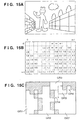
- a scene such as the one shown in Fig. 15A
- a pair of image sensing devices such as CCDs
- an optical device such as a camera
- Two images, sensed by the pair of image sensing devices, which have parallax are respectively divided into M ⁇ n blocks.
- the correlation operation is performed on every block, and distance distribution information of M ⁇ n blocks as shown in Fig. 15B is obtained.
- the numerals in Fig. 15B denote distance values or defocused values.
- the blank blocks are where it is determined that reliability of the result of correlation operation performed on these blocks is low due to low contrast of image signals, for instance.
- grouping of blocks is performed in order to separate objects, in the object space, on the sensed images.
- the M ⁇ n blocks are combined into areas each includes each object as shown in Fig. 15C. Note that the hatched portions in Fig. 15C correspond to the blank blocks in Fig. 15B and are determined that reliability of the result of correlation operation in these areas is low due to low contrast of image signals, for instance.
- a method of grouping there is a method of determining similarity of adjoining blocks by, e.g., comparing the values of the adjoining blocks shown in Fig. 15B, and determining that the adjoining blocks are composed of the same object if the similarity is high, whereas, determining that they are composed of different objects if the similarity is low.
- the distance distribution information to be used for the grouping is simple values, such as distance values or defocused values; however, in a case where the block is very small, fine distance distribution information can be obtained, the information is often vectors normal to surfaces.
- a distance value of a given block as shown in Fig. 15B is compared to respective distance values of its adjoining blocks, and if the difference between the distance values of the adjoining two blocks is within a predetermined threshold, then it is determined that "the objects in the blocks compose the same object". Whereas, if the distance is greater than the threshold, then it is determined that "the object in the blocks compose different objects.”
- blocks are grouped into common objects. The grouped blocks which compose each object are dealt with as a group.
- characteristics such as average distances to the objects, widths, heights, and positions of the groups in the frame, are obtained for all the groups GR1 to GR7, and evaluated as a whole, thereby determining the group which is considered to include the main object.
- likelihood (possibility) of the group having the main object is obtained using a predetermined function, such as the following equation 1, then the obtained values are evaluated.
- (possibility) W1 ⁇ (width) ⁇ (height) + W2/(distance from the center of frame) + W3/(average distance)
- W1, W2, and W3 are constants for weighting items, "distance from the center of frame” is the distance between the center of the frame and the center of mass of the group, and “average distance” is an average of distances to the object from the camera in all the blocks of each group. The probability is calculated for every group, and the group having the largest probability is determined as including the main object.
- a focal length is determined on the basis of the distance information of the group, determined as including the main object, so as to focus on an object in the group, then the lens is actually moved to focus on the object.
- an area including the main object is automatically determined on the basis of the aforesaid information, for instance, and focus control is performed on the basis of the determined result.
- the present invention has been made in consideration of the above situation, and has as a concern to provide an optical device and method for selecting a distance measurement point capable of correctly selecting an object which an operator intends to focus on, and focussing on the selected object.
- United States Patent Specification No. US-4994843 discloses a focus indicating apparatus for an automatic focussing camera.
- an optical measuring area is selected from fixed measuring areas 20a, 20b, 20c so that a photographer cannot select an object which is outside these fixed measuring areas.
- an optical device as defined in claim 1.
- the optical device comprises among others
- a second aspect of the present invention is defined in claim 13.
- the method of focussing an optical device comprises among others the steps of:
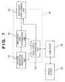
- Fig. 1 is a block diagram showing basic elements of a camera according to the first embodiment of the present invention.
- reference numeral 51 denotes a distance distribution generation unit for measuring the distance to an arbitrary point in the object space
- 52 a main object area determination unit for determining an area which most probably includes the main object (referred to as “main object area” hereinafter) in the sensed image
- 53 a main object area changing unit for changing the main object area, determined automatically, to another area in response to a manual input
- 54 a focal length determination unit for determining a control value to control the focus point of an optical system 55 on the basis of information on the determined main object area
- 55 the optical system for sensing an image
- 56 a lens driver for driving the lens to focus.
- a dot line 57 is for indicating units which are realized by a CPU, RAM and ROM of a computer. Since the distance distribution generation unit 51 is realized with the computer and an optical system for distance measurement, and the main object area changing unit 53 is realized with the computer and an operation member, these units are shown on the dot line 57.
- Fig. 2 shows an optical arrangement of optical elements, of the camera, for measuring the distance to a point in the object space.
- reference numeral 1 denotes an image sensing lens; 8, a field lens; 9, secondary focusing lenses; and 10, an area sensor. Fluxes, introduced by the image sensing lens 1 through different positions, incident on two image forming areas 10a and 10b of the area sensor 10 in the magnification determined by the powers of the field lens 8 and the secondary focusing lenses 9.
- the area sensor 10 is arranged on a conjugate plane of a film to be exposed with respect to the image sensing lens 1, and all or a part of an image to be sensed is formed on each of the image forming areas 10a and 10b.
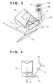
- Fig. 3 is a perspective view showing an arrangement of the optical system for measuring the distance, shown in Fig. 2, when it is applied to the camera.
- reference numeral 6 denotes a quick return mirror; 18, a pentaprism; 19, a light-splitting prism; and 20, a full-reflection mirror.
- Other reference numerals in Fig. 3 are same as those explained with reference to Fig. 2.
- Fig. 4 is a top view when the arrangement shown in Fig. 3 is overlooked from above.
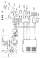
- Fig. 5 is a circuit diagram illustrating a configuration of the camera having the aforesaid optical system'. First, each unit is explained.
- PRS denotes a camera controller, which may be a one-chip microcomputer having a CPU, ROM, RAM, and analog-digital converter.
- the camera controller PRS performs a series of operations of the camera, such as automatic exposure control, automatic focus control, and advancing and rewinding of a film, on the basis of sequence program stored in the ROM.
- the camera controller PRS communicates with inside circuits of the camera and a lens control unit using communication signals SO and SI, a synchronizing clock SCLK, and communication selection signals CLCM, CDDR and CICC, to control operation of each circuit and lens.
- SO is a data signal outputted from the camera controller PRS
- SI is a data signal inputted to the camera controller PRS
- SCLK is a synchronizing clock for signals SO and SI.
- reference LCM denotes a lens communication buffer circuit, and it supplies electric power to a power input terminal VL for the lens when the camera is under operation, further, when the selection signal CLCM from the camera controller PRS is in high potential level (referred as "H”, and low potential level is referred as “L”, hereinafter), it acts as a communication buffer between the camera controller PRS and the lens.
- H high potential level
- L low potential level
- the lens communication buffer circuit LCM When the camera controller PRS controls the selection signal CLCM to be "H” and outputs predetermined data, such as the data signal SO, in synchronization with the synchronizing clock SCLK, the lens communication buffer circuit LCM outputs buffer signals LCK and DCL corresponding to the synchronizing clock SCLK and the data signal LO, respectively, to the lens via a communication node between the camera controller PRS and the lens.
- a buffer signal of the signal DLC is outputted from a lens unit LNS as the data signal SI, and the camera controller PRS receives data of the lens as the data signal SI in synchronization with the synchronizing clock SCLK.
- Reference DDR denotes a circuit for detecting operation of various switches SWS and for display. It is selected when the signal CDDR is "H", and controlled by the camera controller PRS by using the data signals SO and SI, and the synchronizing clock SCLK. More specifically, the circuit DDR changes the displayed contents on a display member DSP of the camera on the basis of data sent from the camera controller PRS, and notifies the camera controller PRS of the ON/OFF state of each of the operation switches SWS of the camera. The state of the rotary operation member of the main object area changing unit 53 is also detected by the circuit DDR.
- Reference OLC denotes an outside liquid crystal display provided in the upper portion of the camera
- reference ILC denotes a liquid crystal display inside of a finder.
- Switches SW1 and SW2 are coupled with a shutter release button (not shown), and with a half press of the shutter release button, the switch SW1 is turned on, and with a full press of the shutter release button, the switch SW2 is turned on.
- the camera controller PRS performs photometry and automatic focus adjustment in response to the "on" operation of the switch SW1, and in response to the "on” operation of the switch SW2, it controls exposure, thereafter, advances the film one frame.
- the switch SW2 is connected to an interruption input terminal of the camera controller PRS, and even when programs triggered by the "on” operation of the switch SW1 is under execution, the "on” operation of the switch SW2 interrupts the execution, and the camera controller PRS swiftly moves to a predetermined interrupt program.
- Reference MTR1 denotes a motor for advancing the film
- reference MTR2 denotes a motor for moving a mirror in the up and down direction and charging of a shutter spring, and the film and the mirror are controlled to move in the forward and reverse directions by the motors MDR1 and MDR2, respectively.
- Signals M1F, M1R, M2F and M2R, inputted from the camera controller PRS to driving circuits MDR1 and MDR2, are forward and reverse rotation control signals.
- References MG1 and MG2 denote front and rear curtain operation magnets, which are supplied with electric power via amplifying transistors TR1 and TR2 in response to control signals SMG1 and SMG2, and the shutter is controlled by the camera controller PRS.
- the motor driving circuits MDR1 and MDR2 and shutter control are not directly related to the present invention, therefore, detailed explanation of them are omitted.
- a buffer signal DCL which is inputted to the lens controller LPRS in synchronization with the buffer signal LCK is instruction data from the camera controller PRS to the lens unit LNS, and operation of the lens unit LNS corresponding to each instruction is predetermined.
- the lens controller LPRS analyzes the instruction in a predetermined procedure, and outputs operation states of focusing control, iris diaphragm control, the output signal DLC, each element of the lens unit LNS (e.g., operation states of focusing control optical system and operation states of iris diaphragm), and various parameters (open f-number, focus distance, coefficient of amount of movement of focusing control optical system corresponding to defocus amount, various focus correction amounts, etc.)
- a zoom lens is explained in the first embodiment as an example, and when an instruction for focus adjustment is transmitted from the camera controller PRS, a motor LMTR for focus adjustment is operated on the basis of the signals LMF and LMR showing an amount and direction of displacement which are transmitted simultaneously. Accordingly, focus adjustment is performed by either rotating the optical system in the forward or reverse direction along the optical axis.
- the amount of displacement of the optical system is obtained in the following manner. First, a pattern of a pulse board, which rotates, coupled with the optical system, is detected by a photocoupler, monitoring a pulse signal SENCF outputted from an encoder ENCF which outputs pulses whose number corresponds to the displacement amount.
- the number of the pulses SENCF is counted by a counter (not shown) provided inside of the lens controller LPRS.
- a counter not shown
- the lens controller LPRS controls the signals LMF and LMR to "L" to operate the motor LMTR.
- the camera controller PRS does not care about operation of the lens until the lens finishes displacement. Further, the lens controller LPRS transmits the value of the counter to the camera controller PRS when the camera controller PRS requests to do so.
- a stepping motor DMTR which is known for driving an iris diaphragm, is operated based on an iris diaphragm stage number transmitted at the same time. Note, since the stepping motor DMTR can control the opening of the iris diaphragm, an encoder for monitoring the operation is not necessary.
- Reference ENCZ denotes an encoder attached to a zoom optical system
- the lens controller LPRS detects the zoom position by receiving a signal SENCZ from the encoder ENCZ.
- the lens controller LPRS stores lens parameters corresponding to respective zoom positions, and outputs a parameter corresponding to a current zoom position to the camera controller PRS when the camera controller PRS requests to do so.
- Reference ICC denotes an area sensor unit including area sensors, such as CCDs, and an operation circuit for operating the area sensors, which is used for focus state detection and photometry.
- the area sensor unit ICC is selected when the selection signal CICC is "H", and controlled by the camera controller PRS using the data signals SO and SI, and the synchronizing clock SCLK.
- ⁇ V and ⁇ H are read signals for the area sensors, and ⁇ R is a reset signal.
- These sensor signals are generated by a driving circuit provided inside of the area sensor unit ICC on the basis of signals from the microcomputer PRS.
- the signals outputted from the area sensors are amplified, then inputted into an analog signal input terminal of the microcomputer PRS as output signals IMAGE. Thereafter, the microcomputer PRS converts the analog output signals IMAGE into digital signals, and the values of the digital signals are sequentially stored in the RAM at predetermined addresses. With these digitized signals, to generate distance distribution information in the object space, focus control, or photometry is performed.
- Reference DL denotes a rotary operation member, which is used for indicating the direction to change the main object area, which will be explained later. Further, reference DLS denotes a sensor for detecting the rotated direction of the rotary operation member DL, which outputs a signal RTDR indicating the detected direction to the camera controller PRS.
- the camera body and the lens are described detachable (i.e., lenses are exchangeable) in Fig. 5; however, the present invention is not limited to the camera of this type. For example, it is possible to apply the present invention to a camera whose camera body and lens are integrally composed.
- an image sensing operation starts in step S100 when an operator presses a shutter release button (not shown), for instance.
- step S101 a sub-routine for generating distance distribution information (distance distribution generation processing) in the object space is called by the distance distribution generation unit 51.
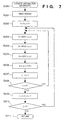
- Fig. 7 is a flowchart showing the distance distribution generation processing.
- step S201 in Fig. 7 images are read from the area sensors.
- the image are read in the following manner.
- the area sensors are reset. More specifically, by controlling the control signals ⁇ V, ⁇ H and ⁇ R to be "H" simultaneously for a predetermined period, residual charges are drained and the area sensor is reset.
- the camera controller PRS transmits an instruction to start charging, and accumulation of charges starts in response to the instruction. After a predetermined period elapses, the accumulation of charges ends.
- control signals ⁇ V and ⁇ H are controlled to drive the area sensors to sequentially output image signals IMAGE, which are A/D converted and stored in RAM in the camera controller PRS. Accordingly, image reading operation in step S201 is completed.
- the output image signals from the two area sensors are stored as IMG1 and IMG2 in a predetermined area of the RAM.
- each of the images IMG1 and IMG2 obtained from the two area sensors is divided into M ⁇ n blocks and defocus distribution (defocus map) is generated in step S202 and its subsequent steps.
- step S202 variables x and y, which are for indicating a block, are initialized.
- step S203 luminance signals necessary for performing distance measuring operation for a block B(x, y), i.e., luminance signals of the block obtained from one of the area sensors, are extracted from the image data IMG1 stored in the RAM, and copied in the RAM at predetermined addresses A.
- step S204 luminance signals necessary for performing distance measuring operation for the block B(x, y) are extracted from the image data IMG2, and copied in the RAM at predetermined addresses B.
- step S205 a known correlation operation COR(x, y) is performed on the luminance signals (luminance distribution signals) recorded at the addresses A and B, and a phase difference between the two luminance distributions is calculated.
- step S206 a distance value or a defocused amount is obtained using any known function F() on the basis of the phase difference between luminance distributions calculated in step S205, and stored in the RAM at an address D(x, y) which is reserved for recording distance distribution information.
- step S207 the variable x is increased by 1 to move a block to be processed to the next block.
- step S208 x and the division number M in the x direction are compared, and if it is determined in step S208 that x is less than M, then the process returns to step S203, and a distance value or a defocused amount of the next block in the x direction is calculated and stored. If it is determined in step S208 that x is equal to or greater than M, then the process moves to step S209, where x is initialized to 0 and y is increased by 1.
- step S210 y and the division number n in the y direction are compared, and if it is determined that y is less than n, then the process returns to step S203 and the operation for the next row starts. Whereas, if it is determined that y is equal to or greater than n, then the process proceeds to step S211, where operation for obtaining a distance value or a defocused amount of every block has been completed. Accordingly, the distance distribution generation sub-routine of step S101 in Fig. 6 is completed.
- step S102 a sub-routine for detecting a main object area (main object area detection processing) is called by the main object area determination unit 52.
- the contents of the main object area detection sub-routine are explained with reference to Fig. 8.
- step S301 in Fig. 8 operation for numbering respective objects (groups), configuring the object space, is performed.
- the results of determination are stored in the RAM at reserved addresses G(0, 0) to G(M-1, n-1).
- respective blocks of the sensed image as shown in Fig. 12A are labeled group numbers for respective groups as shown in Fig. 12B.
- the numbering processing as described above is a known technique called "labeling method", and a flowchart of grouping of the blocks is omitted. Further determination method of determining whether or not two blocks belong to an identical group is disclosed in the Japanese Patent Laid-Open Application No. 10-161013; accordingly, detailed explanation of the method is omitted.
- the number of groups detected in step S301 is set to a variable Gnum in step S302.
- step S303 characteristics of each group forming the sensed image are evaluated, and a group which most probably includes a main object (main object area) is determined out of all the groups (object areas) on the basis of the evaluated characteristics.
- a variable Gcur which denotes a group to be processed is set to 1.
- step S304 a likelihood (probability), S(Gcur), of a block or blocks, forming a group Gcur, of including a main object is calculated.
- the probability S(Gcur) is determined on the basis of an average distance to an object included in the group, width and height of the group, and the location of the group in the image.
- a group which is considered to include the main object is determined on the basis of the calculated probabilities of all the groups.
- the equation 1, described above may be used.
- step S305 the value of Gcur is increased by 1, and the group subjected to the operation is proceeded to the next group.
- step S306 Gcur and Gnum are compared to check whether or not the operation has been performed on all the groups. If Gcur is equal to or less than Gnum, then all the groups have not been processed; therefore, the process returns to step S304. Whereas, if Gcur is greater then Gnum, then the process proceeds to step S307.
- step S307 using a function MAX, a group number having the maximum probability among the probabilities S(1) to S(Gnum) is found, and the group number having the greatest probability substitutes a variable Gmain.
- the blocks labeled the same group number as Gmain are determined as forming the main object area.
- step S308 the main object area detection processing is completed; thus step S102 in Fig. 6 is finished.
- a sub-routine for determining a focal length on the basis of information on the main object area is executed.
- the focal length determination processing is explained with reference to Fig. 9.
- step S401 in Fig. 9 an area, in the object space, subjected to the focal length determination processing is set to the main object area on the basis of the group number detected in step S102.
- step S402 distance information for focus adjustment is calculated on the basis of information on the main object area set in step S102.
- an algorithm which gives priority to the minimum distance in the object area is used, and the minimum distance to the object in the area is calculated.
- step S403 the minimum distance is set as the distance to an object to be focused on; thereby the focal length determination processing is completed, and the process returns to the flowchart in Fig. 6.
- an instruction to control focus is transmitted to the lens from the camera controller PRS so as to focus on a point at the distance determined in step S103, and the lens controller LPRS controls the motor LMTR to focus on the object which is currently considered as the main object in step S104.
- step S105 whether or not the current focus state is proper, namely, whether the main object area which is currently selected includes the main object which the operator intends to focus on, is determined.
- whether or not the operator wishes to change the main object area is checked by detecting a state of the rotary operation member of the main object area changing unit 53 or a state of the switch SW2 of the shutter release button which trigger image sensing operation.
- the rotary operation member of the main object area changing unit 53 is operated before the switch SW2 of the shutter release button is turned on, then it is determined that the operator wishes to change the main object area, whereas, if the switch SW2 is turned on before detecting any operation of the rotary operation member, then it is determined that the operator is satisfied with the main object which is currently set.
- control signals SMG1 and SMG2 to the respective front and rear curtain operation magnets MG1 and MG2 are generated at proper intervals by the camera controller PRS in step S107, the film is exposed, and the image sensing operation is completed.
- step S105 if a change in main object area is requested in step S105, then the process proceeds to step S106, where the process of selecting a main object area is performed.
- step S501 When a change in main object area is requested in step S105 as described above, namely, when the rotary operation member is operated, the direction of the rotation is detected in step S501.
- step S502 When rotation to the left is detected, the process proceeds to step S502, whereas when rotation to the right is detected, the process proceeds to step S503.
- step S502 or S503 on the basis of the rotational direction detected in step S501, an object area on the left or right of the area which is currently selected as the main object area is set as a new main object area; accordingly, the main object area selection process is completed.
- step S106 After the selection of main object area by manual operation is performed in step S106 as described above, the process returns to step S103, where a focal length is determined on the basis of information on the current main object area. Further, the lens is moved in step S104, and whether or not the current main object area is to be changed is determined in step S105, and depending upon the determined result, either exposure operation in step S106 or the main object area selection processing in step S107 is performed.
- step S501 The operation of changing the main object area performed in step S501 and its subsequent steps is explained taking a scene in Fig. 12A as an example. If an object area of group number 3 in Fig. 12B is originally selected as the main object area, and if rotation of the dial to the right is detected in step S501, then an object area of group number 4 is selected as the new main object area, and lens is controlled to focus on an object in the new main object area of group number 4. If rotation of the dial to the right is detected again in step S501, then an object area of group number 6 is selected and set as the new main object area.
- an area selected as the main object area namely, blocks having the identical group number, is surrounded by a line on a screen of a viewfinder.
- a mark may be displayed at a rough center of the main object area.
- the present invention is not limited to this, and two single axis rotary operation members whose rotation axes are orthogonal to each other may be used. In this case, four directions of rotation (i.e., up, down, left and right) may be detected.
- a slide-type direction designation member may be used instead of the rotary operation member.
- an operation member such as a track ball, capable of freely rotating in any direction may be used. In this case, operability of the camera would be improved.
- a priority order may be determined on the basis of the probabilities S(1) to S(Gnum), which are results of evaluation functions, by sorting the probabilities, and the main object area may be changed from an object area having a higher probability to an object area having a lower probability.
- S(1) to S(Gnum) which are results of evaluation functions
- the operation member is a focusing system of an optical device, such as a camera, is explained as the second embodiment.
- Fig. 13 is a block diagram showing basic configuration elements of the camera according to the second embodiment of the present invention.
- reference numerals 51, 52, 54 and 55 refer to the same elements 51, 52, 54 and 55 shown in Fig. 1.
- a main object area changing unit 63 is within a dotted line 67 which represents an area realized by a CPU, RAM and ROM of a computer, and a signal line form the lens driver 66 to the main object area changing unit 63 is added (for notifying the moving direction of focal distance control member), since the function of the operation member in the main object area changing unit 53 is moved to the lens driver 66.
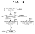
- Fig. 14 is a flowchart of a main object area selection processing according to the second embodiment of the present invention.
- the moving direction of the focusing system (rotation to the right and left when a normal rotation type focusing system is adopted) is determined in step S601, and depending upon the moving direction of either forward (in the approaching direction to the camera) or backward (in the receding direction from the camera), the main object area is changed to an object area which includes an object at a shorter distance in step S603 or an object area which includes an object at a longer distance in step S602.
- the operator when the operator wishes to focus on an object which is at a shorter distance or at a longer distance than the distance where the currently focused object exists, the operator operates the focusing system in the desired direction, and the main object area is automatically changed to an object area which is in the direction the operator desires.
- a main object area which is automatically determined is checked by an operator, and if the determined area is not the area where the operator intends to focus on, it is possible for the operator to change the main object area to an arbitrary area by operating a predetermined operation member.
Landscapes
- Physics & Mathematics (AREA)
- Engineering & Computer Science (AREA)
- Computer Vision & Pattern Recognition (AREA)
- General Physics & Mathematics (AREA)
- Optics & Photonics (AREA)
- Automatic Focus Adjustment (AREA)
- Studio Devices (AREA)
- Length Measuring Devices By Optical Means (AREA)
- Measurement Of Optical Distance (AREA)
- Focusing (AREA)
- Camera Bodies And Camera Details Or Accessories (AREA)
Claims (22)
- Optische Vorrichtung, mit:einem Unterteilungsmittel (51) zum Unterteilen eines von einem optischen Bildaufnahmemittel abgetasteten Bildes in eine Vielzahl von Bereichen;einem Gruppierungsmittel (51) zum Erzeugen einer Fokusabbildung und zum Erzeugen unterteilter Bereiche in Objektbereiche auf der Grundlage der erzeugten Fokusabbildung;einem Hauptobjektbereichsbestimmungsmittel (52) zum Bestimmen eines Hauptobjektbereichs aus den vom Gruppiermittel gruppierten Objektbereichen;einem Fokussteuermittel (54) zum Fokussieren auf dem bestimmten Hauptobjektbereich;einem manuell zu betätigenden Bedienglied zum Ändern des Hauptobjektbereich; und miteinem Hauptobjektbereichsänderungsmittel (53, 63, 66, DL) zum Bestimmen, ob der Nutzer die Betätigung zum Ändern des Hauptobjektbereichs des Bediengliedes während der Periode ausgeführt hat, nachdem das Fokussteuermittel den aktuellen Hauptobjektbereich fokussiert hat und bevor das vom optischen Bildaufnahmemittel aufgenommene Bild erfaßt und zur Beibehaltung des Fokuszustands vom Fokussteuermittel auf dem bestimmten Hauptobjektbereich während dieser Periode eingestellt ist, bis bestimmt worden ist, daß das Betätigungsglied betätigt ist, um einen neuen Hauptobjektbereich eines der Objektbereiche einzustellen und dann das Fokussteuermittel zu veranlassen, auf dem neu eingestellten Hauptobjektbereichs zu fokussieren.
- Vorrichtung nach Anspruch 1, bei der das Gruppierungsmittel eingerichtet ist zum Gruppieren der Vielzahl unterteilter Bereiche auf der Grundlage der Abstände zu Gegenständen, einschließlich des aufgenommenen Bildes, und wobei das Hauptobjektbereichsänderungsmittel ein Richtungsbestimmungsmittel aufweist zum Bestimmen einer Richtung in Hinsicht auf die optische Hauptachse in der Vorrichtung zum Bestimmen als neuen Hauptobjektbereichs eines neuen Objektbereichs, zu dem sich der Abstand vom vorherigen Hauptobjektbereich unterscheidet.
- Vorrichtung nach Anspruch 1 oder 2, die des weiteren über ein Bewertungsmittel (52) verfügt, um einen Bewertungsgrad durch Ausführen einer vorbestimmten Operation für jeden der vom Gruppierungsmittel (51) gruppierten Objektbereiche zu berechnen, wobei das Hauptobjektbereichsbestimmungsmittel (52) den Hauptobjektbereich auf der Grundlage des für jeden der Objektbereiche vom Bewertungsgradrechenmittel berechneten Bewertungsgrades bestimmt.
- Vorrichtung nach Anspruch 1, 2 oder 3, bei der das Hauptobjektbereichsänderungsmittel (53, DL) ein Richtungsbestimmungsmittel hat, um eine Richtung zu bestimmen, die unter einem Winkel der optischen Achse der optischen Vorrichtung verläuft.
- Vorrichtung nach einem der vorstehenden Ansprüche, bei der das Richtungsbestimmungsmittel ein wenigstens in zwei Richtungen drehbares Drehbetätigungsglied (DL) ist.
- Vorrichtung nach Anspruch 5, deren Richtungsbestimmungsmittel über eine Vielzahl von Drehbetätigungsgliedern (DL) verfügt.
- Vorrichtung nach einem der Ansprüche 1 bis 3, deren Richtungsbestimmungsmittel ein gleitendes Bestimmungsmittel ist, das wenigstens zwei Richtungen bestimmen kann.
- Vorrichtung nach Anspruch 7, deren Richtungsbestimmungsmittel über eine Vielzahl der gleitenden Bestimmungsglieder verfügt.
- Vorrichtung nach einem der Ansprüche 1, 2 oder 3, deren Richtungsbestimmungsmittel eine Rollkugel ist.
- Vorrichtung nach einem der Ansprüche 2 bis 9, deren Richtungsbestimmungsmittel (63, 66) eingerichtet ist, die Brennweite des optischen Bildaufnahmesystems zu ändern.
- Vorrichtung nach einem der vorstehenden Ansprüche, die des weiteren über ein Prioritätsbestimmungsmittel verfügt, um die Prioritätsreihenfolge zu bestimmen, und wenn eine Ladung im Hauptobjektbereich angefragt ist, wird das Hauptobjektbereichsänderungsmittel (53) so eingerichtet, daß es den Hauptobjektbereich in absteigender Reihenfolge der Prioritätsreihenfolge ändert.
- Vorrichtung nach Anspruch 11, die des weiteren über ein Bewertungsmittel (52) verfügt, um einen Bewertungsgrad durch Ausführen einer vorbestimmten Operation für jeden der Vielzahl von vom Bereichsbestimmungsmittel (51) herausgefundenen Bereichen zu berechnen, wobei das Prioritätsbestimmungsmittel die Prioritätsreihenfolge auf der Grundlage des für jeden der Vielzahl von Bereichen vom Bewertungsgradrechenmittel berechneten Bewertungsgrades bestimmt.
- Verfahren zum Fokussieren einer optischen Einrichtung, mit den Verfahrensschritten:Unterteilen eines vom optischen Bildaufnahmemittel aufgenommenen Bildes in eine Vielzahl von Bereichen;Erzeugen einer Fokusabbildung und Gruppieren der unterteilten Bereiche in Objektbereiche auf der Grundlage der erzeugten Fokusabbildung;Bestimmen eines Hauptobjektbereichs aus den vom Gruppiermittel gruppierten Objektbereichen; undFokussieren des bestimmten Hauptobjektbereichs,Ändern des Hauptobjektbereichs durch ein manuell zu betätigendes Bedienglied;Bestimmen, ob die Operation zur Änderung des Hauptobjektbereichs vom Bedienmittel während der Periode ausgeführt wurde, nachdem das Fokussteuermittel den laufenden Hauptobjektbereich fokussiert hat, und bevor das vom optischen Bildaufnahmemittel aufgenommene Bild erfaßt worden ist, Beibehalten des Fokuszustands, das das Fokussteuermittel auf den bestimmten Hauptobjektbereich während dieser Periode eingestellt hat, bis bestimmt ist, daß das Betätigungsglied zum Einstellen eines neuen Hauptobjektbereichs einer der Objektbereiche betätigt worden ist, und Fokussieren auf den neu eingestellten Hauptobjektbereich.
- Verfahren nach Anspruch 13, bei dem der Gruppierungsschritt die Vielzahl unterteilter Bereiche auf der Grundlage der Entfernungen zu im Bild enthaltenen Gegenständen gruppiert, und bei dem der Hauptobjektbereichsänderungsschritt ein Richtungsbestimmungsmittel verwendet, um die Richtung in Hinsicht auf die optische Hauptachse zu der Vorrichtung zu bestimmen, und als einen neuen Hauptobjektbereich einen Objektbereich zu bestimmen, zu dem sich der Abstand sich vom vorherigen Hauptobjektbereich unterscheidet.
- Verfahren nach Anspruch 13 oder 14, das des weiteren einen Bewertungsgrad durch Ausführen einer vorbestimmten Operation für jeden der Objektbereiche berechnet, die der Gruppierungsschritt gruppiert hat, wobei der Hauptobjektbereichsbestimmungsschritt den Hauptobjektbereich auf der Grundlage des für jeden der Objektbereiche vom Bewertungsgradrechenmittel berechneten Bewertungsgrades bestimmt.
- Verfahren nach einem der Ansprüche 13 bis 15, bei dem der Schritt des Änderns vom Hauptobjektbereich ein wenigstens in zwei Richtungen drehbares Drehbetätigungsglied (DL) verwendet.
- Verfahren nach Anspruch 16, das eine Vielzahl von Drehbetätigungsgliedern (DL) verwendet, um den Hauptobjektbereich zu ändern.
- Verfahren nach einem der Ansprüche 13 bis 15, bei dem der Verfahrensschritt des Änderns vom Hauptobjektbereichs ein gleitfähiges Bestimmungsglied verwendet, das wenigstens zwei Richtungen bestimmen kann.
- Verfahren nach Anspruch 18, das eine Vielzahl von gleitfähigen Bestimmungsgliedern verwendet.
- Verfahren nach einem der Ansprüche 13 bis 15, bei dem der Schritt des Änderns vom Hauptobjektbereich eine Rollkugel verwendet.
- Verfahren nach einem der Ansprüche 13 bis 20, das des weiteren über einem Prioritätsbestimmungsschritt zum Bestimmen einer Prioritätsreihenfolge der Objektbereiche verfügt, und wenn die Änderung im Hauptobjektbereich annulliert ist, ändert der Hauptobjektbereichsänderungsschritt den Hauptobjektbereich in abfallender Prioritätsreihenfolge.
- Verfahren nach Anspruch 21, das des weiteren über einen Bewertungsschritt des Berechnens eines Bewertungsgrades durch Ausführen einer vorbestimmten Operation für jeden der Vielzahl von Objektbereichen verfügt, die der Bereichsbestimmungsschritt unterteilt hat, wobei der Prioritätsbestimmungsschritt die Prioritätsreihenfolge auf der Grundlage des für jeden der Vielzahl von Objektbereichen im Bewertungsgradberechnungsschritt berechneten Bewertungsgrades bestimmt.
Applications Claiming Priority (2)
| Application Number | Priority Date | Filing Date | Title |
|---|---|---|---|
| JP35851297 | 1997-12-25 | ||
| JP35851297A JP4018218B2 (ja) | 1997-12-25 | 1997-12-25 | 光学装置及び測距点選択方法 |
Publications (3)
| Publication Number | Publication Date |
|---|---|
| EP0926526A2 EP0926526A2 (de) | 1999-06-30 |
| EP0926526A3 EP0926526A3 (de) | 1999-12-22 |
| EP0926526B1 true EP0926526B1 (de) | 2005-04-13 |
Family
ID=18459706
Family Applications (1)
| Application Number | Title | Priority Date | Filing Date |
|---|---|---|---|
| EP98310578A Expired - Lifetime EP0926526B1 (de) | 1997-12-25 | 1998-12-22 | Optische Vorrichtung und Verfahren zur Auswahl eines Fokusobjektes |
Country Status (4)
| Country | Link |
|---|---|
| US (1) | US7071985B1 (de) |
| EP (1) | EP0926526B1 (de) |
| JP (1) | JP4018218B2 (de) |
| DE (1) | DE69829734T2 (de) |
Families Citing this family (27)
| Publication number | Priority date | Publication date | Assignee | Title |
|---|---|---|---|---|
| JP4391637B2 (ja) * | 1999-10-04 | 2009-12-24 | オリンパス株式会社 | カメラ |
| US6785469B1 (en) * | 1999-11-16 | 2004-08-31 | Olympus Corporation | Distance measuring device installed in camera |
| JP4550211B2 (ja) * | 2000-03-21 | 2010-09-22 | オリンパス株式会社 | カメラ |
| JP4011829B2 (ja) | 2000-06-14 | 2007-11-21 | キヤノン株式会社 | 撮像装置及びその制御方法 |
| US6956612B2 (en) * | 2001-07-31 | 2005-10-18 | Hewlett-Packard Development Company, L.P. | User selectable focus regions in an image capturing device |
| US7391463B2 (en) * | 2002-08-06 | 2008-06-24 | Olympus Corporation | Image sensing apparatus having distance measuring unit and control method thereof |
| JP3958164B2 (ja) | 2002-09-19 | 2007-08-15 | キヤノン株式会社 | カメラの測光装置 |
| US7551223B2 (en) * | 2002-12-26 | 2009-06-23 | Sony Corporation | Apparatus, method, and computer program for imaging and automatic focusing |
| WO2004072725A1 (de) * | 2003-02-12 | 2004-08-26 | Fraunhofer-Gesellschaft Zur Foerderung Der Angewandten Forschung E.V. | Einstellung eines bildaufnehmers mit dynamischen messfeldern |
| US7705908B2 (en) * | 2003-12-16 | 2010-04-27 | Eastman Kodak Company | Imaging method and system for determining camera operating parameter |
| JP2005269604A (ja) * | 2004-02-20 | 2005-09-29 | Fuji Photo Film Co Ltd | 撮像装置、撮像方法、及び撮像プログラム |
| JP4154400B2 (ja) * | 2004-04-01 | 2008-09-24 | キヤノン株式会社 | 撮像装置及びその制御方法及びプログラム |
| TWI315152B (en) * | 2006-05-19 | 2009-09-21 | Primax Electronics Ltd | Image object location detection method |
| JP2008170645A (ja) * | 2007-01-10 | 2008-07-24 | Olympus Corp | フォーカス制御装置及び撮像装置 |
| JP4873729B2 (ja) | 2007-04-06 | 2012-02-08 | キヤノン株式会社 | 光学機器 |
| US20130083232A1 (en) * | 2009-04-23 | 2013-04-04 | Hiok Nam Tay | Auto-focus image system |
| JP5246078B2 (ja) * | 2009-07-10 | 2013-07-24 | 株式会社ニコン | 被写体位置特定用プログラム、およびカメラ |
| SG181173A1 (en) | 2009-12-07 | 2012-07-30 | Hiok Nam Tay | Auto-focus image system |
| GB2487144B (en) * | 2010-05-26 | 2014-11-19 | Hiok-Nam Tay | Auto-focus image system |
| GB2510495A (en) * | 2010-05-26 | 2014-08-06 | Hiok Nam Tay | Auto-focus image system |
| JP2012141240A (ja) * | 2011-01-05 | 2012-07-26 | Ricoh Co Ltd | 測距装置、測距方法および撮像装置、撮像方法 |
| US9065999B2 (en) | 2011-03-24 | 2015-06-23 | Hiok Nam Tay | Method and apparatus for evaluating sharpness of image |
| JP6550643B2 (ja) * | 2014-03-14 | 2019-07-31 | 本田技研工業株式会社 | 動作推定装置、ロボット、及び動作推定方法 |
| JP6577703B2 (ja) | 2014-08-05 | 2019-09-18 | キヤノン株式会社 | 画像処理装置及び画像処理方法、プログラム、記憶媒体 |
| JP6611477B2 (ja) * | 2015-06-08 | 2019-11-27 | キヤノン株式会社 | 撮像装置、発光制御方法、プログラム |
| SE541141C2 (en) * | 2016-04-18 | 2019-04-16 | Moonlightning Ind Ab | Focus pulling with a stereo vision camera system |
| JP2018189443A (ja) | 2017-04-28 | 2018-11-29 | キヤノン株式会社 | 距離測定装置、距離測定方法及び撮像装置 |
Citations (2)
| Publication number | Priority date | Publication date | Assignee | Title |
|---|---|---|---|---|
| JPH09127405A (ja) * | 1995-10-27 | 1997-05-16 | Canon Inc | 光学装置 |
| JPH09211316A (ja) * | 1996-01-31 | 1997-08-15 | Canon Inc | 像信号処理装置 |
Family Cites Families (85)
| Publication number | Priority date | Publication date | Assignee | Title |
|---|---|---|---|---|
| US4555169A (en) | 1983-09-13 | 1985-11-26 | Canon Kabushiki Kaisha | Focus detecting device for a camera |
| JPS6068510U (ja) | 1983-10-17 | 1985-05-15 | キヤノン株式会社 | 焦点検出装置 |
| JPS60101513A (ja) | 1983-11-08 | 1985-06-05 | Canon Inc | 焦点検出装置 |
| US4520240A (en) * | 1983-12-01 | 1985-05-28 | Texas Instruments Incorporated | Four-way key switch control mechanism |
| JPS60263912A (ja) | 1984-06-13 | 1985-12-27 | Canon Inc | カメラの焦点検出装置 |
| JPS6148807A (ja) | 1984-08-17 | 1986-03-10 | Canon Inc | 焦点検出装置 |
| JPH0629895B2 (ja) | 1984-09-11 | 1994-04-20 | キヤノン株式会社 | フォーカス状態決定装置 |
| JPS6195324A (ja) | 1984-10-16 | 1986-05-14 | Canon Inc | カメラの露出制御装置 |
| JPH067223B2 (ja) | 1984-10-17 | 1994-01-26 | キヤノン株式会社 | 焦点検出装置 |
| JPS61182516A (ja) | 1985-02-09 | 1986-08-15 | Canon Inc | 距離測定方法 |
| US4739157A (en) | 1985-03-19 | 1988-04-19 | Canon Kabushiki Kaisha | Method of detecting the correlation between signals with weighting |
| US4849782A (en) | 1985-06-28 | 1989-07-18 | Canon Kabushiki Kaisha | Focus detecting device |
| JPH0731300B2 (ja) | 1985-09-21 | 1995-04-10 | キヤノン株式会社 | 焦点検出装置 |
| GB2183419B (en) | 1985-10-22 | 1990-08-29 | Canon Kk | Focusing state detection apparatus for objective lens |
| US4792668A (en) | 1985-12-05 | 1988-12-20 | Canon Kabushiki Kaisha | Apparatus for detecting focusing state of objective lens |
| US4801963A (en) | 1985-12-18 | 1989-01-31 | Canon Kabushiki Kaisha | Focus detecting system |
| US4792669A (en) | 1986-01-10 | 1988-12-20 | Canon Kabushiki Kaisha | Focus detecting device having two selectively movable lenses |
| US4728785A (en) | 1986-01-10 | 1988-03-01 | Canon Kabushiki Kaisha | Focus detecting device using adjustable inclined sensing means |
| US4907026A (en) | 1986-04-21 | 1990-03-06 | Canon Kabushiki Kaisha | Light projection system for automatic focus detection |
| JPS6318313A (ja) | 1986-07-10 | 1988-01-26 | Canon Inc | 焦点検出装置 |
| JP2692049B2 (ja) | 1986-07-10 | 1997-12-17 | キヤノン株式会社 | 焦点検出装置 |
| JPS6318312A (ja) | 1986-07-10 | 1988-01-26 | Canon Inc | 焦点検出装置 |
| US4774539A (en) | 1986-10-01 | 1988-09-27 | Canon Kabushiki Kaisha | Camera having a focus detecting apparatus |
| US4959677A (en) | 1986-10-01 | 1990-09-25 | Canon Kabushiki Kaisha | Device for detecting the focus adjusted state of an objecting lens |
| JPS63118112A (ja) | 1986-11-05 | 1988-05-23 | Canon Inc | 焦点検出装置 |
| JPS6392314U (de) | 1986-12-05 | 1988-06-15 | ||
| US4855777A (en) | 1987-03-02 | 1989-08-08 | Canon Kabushiki Kaisha | Apparatus for detecting the focus adjusted state of an objective lens |
| US5003400A (en) * | 1987-08-19 | 1991-03-26 | Hitachi, Ltd. | Focusing apparatus of video camera or the like |
| US5005041A (en) | 1987-11-05 | 1991-04-02 | Canon Kabushiki Kaisha | Focus detecting apparatus having a plurality of focus detecting areas |
| JPH01134410A (ja) | 1987-11-20 | 1989-05-26 | Canon Inc | 自動焦点調節装置 |
| US4998124A (en) * | 1987-11-26 | 1991-03-05 | Minolta Camera Kabushiki Kaisha | Autofocus camera including automatically controlled focus adjustment |
| JPH07117645B2 (ja) | 1987-12-14 | 1995-12-18 | キヤノン株式会社 | 焦点検出装置 |
| JPH0617935B2 (ja) | 1987-12-24 | 1994-03-09 | キヤノン株式会社 | 自動焦点調節装置 |
| JPH01177507A (ja) | 1988-01-06 | 1989-07-13 | Canon Inc | 自動焦点装置を有するカメラ |
| US4908645A (en) | 1988-02-05 | 1990-03-13 | Canon Kabushiki Kaisha | Automatic focus adjusting device |
| US5060002A (en) | 1988-02-11 | 1991-10-22 | Canon Kabushiki Kaisha | Automatic focus adjusting device |
| JPH01213614A (ja) | 1988-02-22 | 1989-08-28 | Canon Inc | 自動焦点調節装置 |
| US4980716A (en) | 1988-04-28 | 1990-12-25 | Canon Kabushiki Kaisha | Focus detecting device |
| JPH01280713A (ja) | 1988-05-06 | 1989-11-10 | Canon Inc | 自動焦点調節装置 |
| JPH01285907A (ja) | 1988-05-13 | 1989-11-16 | Canon Inc | カメラのための自動焦点調節装置 |
| JP2713978B2 (ja) | 1988-05-13 | 1998-02-16 | キヤノン株式会社 | カメラのための自動焦点調節装置 |
| JP2643326B2 (ja) | 1988-07-07 | 1997-08-20 | キヤノン株式会社 | 焦点検出装置を有した一眼レフカメラ |
| JPH0812319B2 (ja) | 1988-07-19 | 1996-02-07 | キヤノン株式会社 | カメラ |
| US4992817A (en) | 1988-08-06 | 1991-02-12 | Canon Kabushiki Kaisha | Focus detecting device switching between passive and active detection |
| GB2222337B (en) * | 1988-08-25 | 1992-12-16 | Asahi Optical Co Ltd | Automatic focusing camera |
| US5333028A (en) | 1988-08-30 | 1994-07-26 | Canon Kabushiki Kaisha | Automatic focusing apparatus detecting focus for a plurality of areas and using contrast levels |
| GB2223139B (en) | 1988-08-31 | 1993-03-03 | Canon Kk | Automatic focusing apparatus |
| GB2223140B (en) | 1988-08-31 | 1993-03-03 | Canon Kk | Automatic focusing apparatus for camera |
| US5089843A (en) | 1989-01-09 | 1992-02-18 | Canon Kabushiki Kaisha | Auto focus device with predictive focussing |
| JPH02189533A (ja) | 1989-01-19 | 1990-07-25 | Canon Inc | 自動焦点調節装置 |
| US5629735A (en) * | 1989-08-20 | 1997-05-13 | Canon Kabushiki Kaisha | Image sensing device having a selectable detecting area |
| US4992819A (en) | 1989-10-31 | 1991-02-12 | Canon Kabushiki Kaisha | Focus detecting device having a plurality of detecting areas and camera provided with the same |
| JP2756330B2 (ja) * | 1990-01-16 | 1998-05-25 | キヤノン株式会社 | 自動焦点調節装置 |
| US5235428A (en) * | 1990-02-21 | 1993-08-10 | Sony Corporation | Auto-focus system for video camera |
| US5103254A (en) * | 1990-05-29 | 1992-04-07 | Eastman Kodak Company | Camera with subject highlighting and motion detection |
| JPH0467607A (ja) | 1990-07-09 | 1992-03-03 | Nippondenso Co Ltd | 突合せ型変圧器 |
| JPH0478832A (ja) | 1990-07-20 | 1992-03-12 | Canon Inc | 焦点検出装置 |
| US5659823A (en) * | 1990-08-29 | 1997-08-19 | Minolta Camera Kabushiki Kaisha | Camera |
| US5138260A (en) * | 1990-11-21 | 1992-08-11 | Picker International, Inc. | Computer controlled switching of multiple rf coils |
| JPH05233141A (ja) * | 1992-02-25 | 1993-09-10 | Mitsubishi Electric Corp | ポインティングデバイス |
| US5365302A (en) * | 1992-05-01 | 1994-11-15 | Olympus Optical Company, Ltd. | Focus area setting apparatus of camera |
| US5392088A (en) * | 1992-09-04 | 1995-02-21 | Nikon Corporation | Target follow-up device and camera comprising the same |
| DE4231379C2 (de) * | 1992-09-19 | 2001-09-13 | Leica Microsystems | Mikroskop mit einem multifunktionalen Triebknopf |
| US5625415A (en) * | 1993-05-20 | 1997-04-29 | Fuji Photo Film Co., Ltd. | Apparatus and method for automatic focusing in a camera system |
| JP3144155B2 (ja) | 1993-05-20 | 2001-03-12 | キヤノン株式会社 | 焦点検出装置 |
| US5682559A (en) * | 1993-09-30 | 1997-10-28 | Minolta Co., Ltd. | Camera |
| US5900927A (en) * | 1993-10-13 | 1999-05-04 | Fuji Photo Film Co., Ltd. | Variable target autofocusing and range finder for measuring distance to a subject |
| JP3382321B2 (ja) | 1993-11-08 | 2003-03-04 | キヤノン株式会社 | 光学機器 |
| US5615398A (en) | 1993-11-08 | 1997-03-25 | Canon Kabushiki Kaisha | Optical apparatus with image area sensors for controlling lens focal length |
| US5640619A (en) * | 1993-12-14 | 1997-06-17 | Nikon Corporation | Multiple point focus detection camera |
| JPH08138053A (ja) * | 1994-11-08 | 1996-05-31 | Canon Inc | 被写体情報処理装置及び遠隔装置 |
| US5496106A (en) * | 1994-12-13 | 1996-03-05 | Apple Computer, Inc. | System and method for generating a contrast overlay as a focus assist for an imaging device |
| US5729771A (en) | 1995-01-20 | 1998-03-17 | Canon Kabushiki Kaisha | Focus detecting apparatus and optical apparatus using it |
| JP3477279B2 (ja) * | 1995-05-29 | 2003-12-10 | ペンタックス株式会社 | 視線検出装置 |
| JP3146931B2 (ja) * | 1995-06-30 | 2001-03-19 | 富士写真光機株式会社 | オートフォーカスカメラ |
| US5745175A (en) * | 1995-10-02 | 1998-04-28 | Flashpoint Technologies, Inc. | Method and system for providing automatic focus control for a still digital camera |
| US5913082A (en) * | 1995-10-27 | 1999-06-15 | Canon Kabushiki Kaisha | Image signal processing apparatus |
| JP3636524B2 (ja) | 1995-12-28 | 2005-04-06 | キヤノン株式会社 | 焦点検出装置及びそれを用いた光学機器 |
| JP3571835B2 (ja) | 1995-12-28 | 2004-09-29 | キヤノン株式会社 | 焦点検出装置及びそれを用いた光学機器 |
| US5839001A (en) | 1995-12-28 | 1998-11-17 | Canon Kabushiki Kaisha | Focus detecting apparatus |
| JP3733392B2 (ja) * | 1996-03-05 | 2006-01-11 | イーストマン コダック カンパニー | 画像の構図変化検出方法 |
| US6404906B2 (en) * | 1997-03-03 | 2002-06-11 | Bacus Research Laboratories,Inc. | Method and apparatus for acquiring and reconstructing magnified specimen images from a computer-controlled microscope |
| JPH10161013A (ja) * | 1996-12-05 | 1998-06-19 | Canon Inc | 環境認識装置及び環境認識装置を備えたカメラ |
| JP3927655B2 (ja) * | 1997-07-31 | 2007-06-13 | キヤノン株式会社 | カメラ |
| KR19990030882A (ko) * | 1997-10-07 | 1999-05-06 | 이해규 | 초점 위치 조절이 가능한 디지탈 스틸 카메라 및 그 제어 방법 |
-
1997
- 1997-12-25 JP JP35851297A patent/JP4018218B2/ja not_active Expired - Fee Related
-
1998
- 1998-12-22 DE DE69829734T patent/DE69829734T2/de not_active Expired - Lifetime
- 1998-12-22 EP EP98310578A patent/EP0926526B1/de not_active Expired - Lifetime
- 1998-12-22 US US09/217,937 patent/US7071985B1/en not_active Expired - Fee Related
Patent Citations (2)
| Publication number | Priority date | Publication date | Assignee | Title |
|---|---|---|---|---|
| JPH09127405A (ja) * | 1995-10-27 | 1997-05-16 | Canon Inc | 光学装置 |
| JPH09211316A (ja) * | 1996-01-31 | 1997-08-15 | Canon Inc | 像信号処理装置 |
Also Published As
| Publication number | Publication date |
|---|---|
| JP4018218B2 (ja) | 2007-12-05 |
| DE69829734D1 (de) | 2005-05-19 |
| DE69829734T2 (de) | 2005-09-29 |
| US7071985B1 (en) | 2006-07-04 |
| EP0926526A3 (de) | 1999-12-22 |
| EP0926526A2 (de) | 1999-06-30 |
| JPH11190816A (ja) | 1999-07-13 |
Similar Documents
| Publication | Publication Date | Title |
|---|---|---|
| EP0926526A2 (de) | Optische Vorrichtung und Verfahren zur Auswahl eines Fokusobjektes | |
| US4878079A (en) | Focus detecting device | |
| US5890021A (en) | Distance detecting device, focus state detecting device and camera having same | |
| US5365302A (en) | Focus area setting apparatus of camera | |
| US4816861A (en) | Focus condition detecting device | |
| US5091742A (en) | Camera having an auto focusing device | |
| JPH1125263A (ja) | 対象物特徴点検出装置、焦点調節装置、露出制御装置及びカメラ | |
| JPH10142490A (ja) | 環境認識装置及びカメラ | |
| EP0438116B1 (de) | Einrichtung zur Fokussierungsdetektierung | |
| US4994841A (en) | Automatic focus detecting means | |
| JPH1138313A (ja) | 光学装置及びカメラ | |
| EP2053438B1 (de) | Fokussierungsdetektor, Abstandsmesser und optisches Gerät zur Fokusanpassung | |
| US5293034A (en) | Focus state detection device | |
| US5315341A (en) | Method and apparatus for through-the-lens distance determination | |
| US5862415A (en) | Auto-focusing camera with panning state detection function | |
| US5144357A (en) | Automatic focus detecting means | |
| JP4011738B2 (ja) | 光学装置 | |
| EP0438140B1 (de) | Scharfeinstellungsgerät in einer Kamera | |
| JPH04235512A (ja) | グル−プ化機能を有する焦点検出装置 | |
| JP3728604B2 (ja) | 焦点検出装置 | |
| JP2974637B2 (ja) | 自動焦点調節装置 | |
| JPH0876002A (ja) | 自動焦点調節装置 | |
| JP2610235B2 (ja) | 焦点検出装置 | |
| EP0439167A1 (de) | Scharfeinstellungssuchgerät | |
| JP3374526B2 (ja) | カメラの測距装置 |
Legal Events
| Date | Code | Title | Description |
|---|---|---|---|
| PUAI | Public reference made under article 153(3) epc to a published international application that has entered the european phase |
Free format text: ORIGINAL CODE: 0009012 |
|
| AK | Designated contracting states |
Kind code of ref document: A2 Designated state(s): DE FR GB |
|
| AX | Request for extension of the european patent |
Free format text: AL;LT;LV;MK;RO;SI |
|
| PUAL | Search report despatched |
Free format text: ORIGINAL CODE: 0009013 |
|
| AK | Designated contracting states |
Kind code of ref document: A3 Designated state(s): AT BE CH CY DE DK ES FI FR GB GR IE IT LI LU MC NL PT SE |
|
| AX | Request for extension of the european patent |
Free format text: AL;LT;LV;MK;RO;SI |
|
| RIC1 | Information provided on ipc code assigned before grant |
Free format text: 6G 02B 7/28 A, 6G 02B 7/34 B |
|
| 17P | Request for examination filed |
Effective date: 20000508 |
|
| AKX | Designation fees paid |
Free format text: DE FR GB |
|
| 17Q | First examination report despatched |
Effective date: 20020718 |
|
| GRAP | Despatch of communication of intention to grant a patent |
Free format text: ORIGINAL CODE: EPIDOSNIGR1 |
|
| GRAS | Grant fee paid |
Free format text: ORIGINAL CODE: EPIDOSNIGR3 |
|
| GRAA | (expected) grant |
Free format text: ORIGINAL CODE: 0009210 |
|
| AK | Designated contracting states |
Kind code of ref document: B1 Designated state(s): DE FR GB |
|
| REG | Reference to a national code |
Ref country code: GB Ref legal event code: FG4D |
|
| REF | Corresponds to: |
Ref document number: 69829734 Country of ref document: DE Date of ref document: 20050519 Kind code of ref document: P |
|
| PLBE | No opposition filed within time limit |
Free format text: ORIGINAL CODE: 0009261 |
|
| STAA | Information on the status of an ep patent application or granted ep patent |
Free format text: STATUS: NO OPPOSITION FILED WITHIN TIME LIMIT |
|
| ET | Fr: translation filed | ||
| 26N | No opposition filed |
Effective date: 20060116 |
|
| REG | Reference to a national code |
Ref country code: FR Ref legal event code: PLFP Year of fee payment: 18 |
|
| PGFP | Annual fee paid to national office [announced via postgrant information from national office to epo] |
Ref country code: GB Payment date: 20151218 Year of fee payment: 18 |
|
| PGFP | Annual fee paid to national office [announced via postgrant information from national office to epo] |
Ref country code: FR Payment date: 20151223 Year of fee payment: 18 |
|
| PGFP | Annual fee paid to national office [announced via postgrant information from national office to epo] |
Ref country code: DE Payment date: 20151231 Year of fee payment: 18 |
|
| REG | Reference to a national code |
Ref country code: DE Ref legal event code: R119 Ref document number: 69829734 Country of ref document: DE |
|
| GBPC | Gb: european patent ceased through non-payment of renewal fee |
Effective date: 20161222 |
|
| REG | Reference to a national code |
Ref country code: FR Ref legal event code: ST Effective date: 20170831 |
|
| PG25 | Lapsed in a contracting state [announced via postgrant information from national office to epo] |
Ref country code: FR Free format text: LAPSE BECAUSE OF NON-PAYMENT OF DUE FEES Effective date: 20170102 |
|
| PG25 | Lapsed in a contracting state [announced via postgrant information from national office to epo] |
Ref country code: GB Free format text: LAPSE BECAUSE OF NON-PAYMENT OF DUE FEES Effective date: 20161222 Ref country code: DE Free format text: LAPSE BECAUSE OF NON-PAYMENT OF DUE FEES Effective date: 20170701 |