EP0937617A2 - Verfahren und Vorrichtung zur Steuerung einer Bremsanlage - Google Patents
Verfahren und Vorrichtung zur Steuerung einer Bremsanlage Download PDFInfo
- Publication number
- EP0937617A2 EP0937617A2 EP98118807A EP98118807A EP0937617A2 EP 0937617 A2 EP0937617 A2 EP 0937617A2 EP 98118807 A EP98118807 A EP 98118807A EP 98118807 A EP98118807 A EP 98118807A EP 0937617 A2 EP0937617 A2 EP 0937617A2
- Authority
- EP
- European Patent Office
- Prior art keywords
- pressure
- wheel
- target
- wheel brake
- emergency braking
- Prior art date
- Legal status (The legal status is an assumption and is not a legal conclusion. Google has not performed a legal analysis and makes no representation as to the accuracy of the status listed.)
- Granted
Links
Images


Classifications
-
- B—PERFORMING OPERATIONS; TRANSPORTING
- B60—VEHICLES IN GENERAL
- B60T—VEHICLE BRAKE CONTROL SYSTEMS OR PARTS THEREOF; BRAKE CONTROL SYSTEMS OR PARTS THEREOF, IN GENERAL; ARRANGEMENT OF BRAKING ELEMENTS ON VEHICLES IN GENERAL; PORTABLE DEVICES FOR PREVENTING UNWANTED MOVEMENT OF VEHICLES; VEHICLE MODIFICATIONS TO FACILITATE COOLING OF BRAKES
- B60T13/00—Transmitting braking action from initiating means to ultimate brake actuator with power assistance or drive; Brake systems incorporating such transmitting means, e.g. air-pressure brake systems
- B60T13/10—Transmitting braking action from initiating means to ultimate brake actuator with power assistance or drive; Brake systems incorporating such transmitting means, e.g. air-pressure brake systems with fluid assistance, drive, or release
- B60T13/66—Electrical control in fluid-pressure brake systems
- B60T13/662—Electrical control in fluid-pressure brake systems characterised by specified functions of the control system components
-
- B—PERFORMING OPERATIONS; TRANSPORTING
- B60—VEHICLES IN GENERAL
- B60T—VEHICLE BRAKE CONTROL SYSTEMS OR PARTS THEREOF; BRAKE CONTROL SYSTEMS OR PARTS THEREOF, IN GENERAL; ARRANGEMENT OF BRAKING ELEMENTS ON VEHICLES IN GENERAL; PORTABLE DEVICES FOR PREVENTING UNWANTED MOVEMENT OF VEHICLES; VEHICLE MODIFICATIONS TO FACILITATE COOLING OF BRAKES
- B60T7/00—Brake-action initiating means
- B60T7/12—Brake-action initiating means for automatic initiation; for initiation not subject to will of driver or passenger
-
- B—PERFORMING OPERATIONS; TRANSPORTING
- B60—VEHICLES IN GENERAL
- B60T—VEHICLE BRAKE CONTROL SYSTEMS OR PARTS THEREOF; BRAKE CONTROL SYSTEMS OR PARTS THEREOF, IN GENERAL; ARRANGEMENT OF BRAKING ELEMENTS ON VEHICLES IN GENERAL; PORTABLE DEVICES FOR PREVENTING UNWANTED MOVEMENT OF VEHICLES; VEHICLE MODIFICATIONS TO FACILITATE COOLING OF BRAKES
- B60T8/00—Arrangements for adjusting wheel-braking force to meet varying vehicular or ground-surface conditions, e.g. limiting or varying distribution of braking force
- B60T8/32—Arrangements for adjusting wheel-braking force to meet varying vehicular or ground-surface conditions, e.g. limiting or varying distribution of braking force responsive to a speed condition, e.g. acceleration or deceleration
- B60T8/34—Arrangements for adjusting wheel-braking force to meet varying vehicular or ground-surface conditions, e.g. limiting or varying distribution of braking force responsive to a speed condition, e.g. acceleration or deceleration having a fluid pressure regulator responsive to a speed condition
- B60T8/40—Arrangements for adjusting wheel-braking force to meet varying vehicular or ground-surface conditions, e.g. limiting or varying distribution of braking force responsive to a speed condition, e.g. acceleration or deceleration having a fluid pressure regulator responsive to a speed condition comprising an additional fluid circuit including fluid pressurising means for modifying the pressure of the braking fluid, e.g. including wheel driven pumps for detecting a speed condition, or pumps which are controlled by means independent of the braking system
- B60T8/4072—Systems in which a driver input signal is used as a control signal for the additional fluid circuit which is normally used for braking
- B60T8/4081—Systems with stroke simulating devices for driver input
- B60T8/4086—Systems with stroke simulating devices for driver input the stroke simulating device being connected to, or integrated in the driver input device
-
- B—PERFORMING OPERATIONS; TRANSPORTING
- B60—VEHICLES IN GENERAL
- B60T—VEHICLE BRAKE CONTROL SYSTEMS OR PARTS THEREOF; BRAKE CONTROL SYSTEMS OR PARTS THEREOF, IN GENERAL; ARRANGEMENT OF BRAKING ELEMENTS ON VEHICLES IN GENERAL; PORTABLE DEVICES FOR PREVENTING UNWANTED MOVEMENT OF VEHICLES; VEHICLE MODIFICATIONS TO FACILITATE COOLING OF BRAKES
- B60T8/00—Arrangements for adjusting wheel-braking force to meet varying vehicular or ground-surface conditions, e.g. limiting or varying distribution of braking force
- B60T8/32—Arrangements for adjusting wheel-braking force to meet varying vehicular or ground-surface conditions, e.g. limiting or varying distribution of braking force responsive to a speed condition, e.g. acceleration or deceleration
- B60T8/88—Arrangements for adjusting wheel-braking force to meet varying vehicular or ground-surface conditions, e.g. limiting or varying distribution of braking force responsive to a speed condition, e.g. acceleration or deceleration with failure responsive means, i.e. means for detecting and indicating faulty operation of the speed responsive control means
- B60T8/92—Arrangements for adjusting wheel-braking force to meet varying vehicular or ground-surface conditions, e.g. limiting or varying distribution of braking force responsive to a speed condition, e.g. acceleration or deceleration with failure responsive means, i.e. means for detecting and indicating faulty operation of the speed responsive control means automatically taking corrective action
- B60T8/94—Arrangements for adjusting wheel-braking force to meet varying vehicular or ground-surface conditions, e.g. limiting or varying distribution of braking force responsive to a speed condition, e.g. acceleration or deceleration with failure responsive means, i.e. means for detecting and indicating faulty operation of the speed responsive control means automatically taking corrective action on a fluid pressure regulator
Definitions
- the invention relates to a method and a device to control a brake system according to the generic terms of independent claims.
- Such a method or device is known for example from SAE paper 960991.
- An electro-hydraulic brake system in which from the brake pedal actuation by the driver The driver's braking request is derived. This braking request If necessary, taking into account other company sizes in target brake pressures for the individual wheel brakes converted.
- the target braking pressures are set for each wheel Pressure control loops based on the specified target pressure and the actual brake pressure measured in the area of the wheel brake adjusted. Since the brake pressure in the wheel brakes at one such electro-hydraulic brake system depending on Driver braking request electronically via valve arrangements is set and modulated is to ensure the operational safety of the brake system monitoring the correct functioning of the pressure modulation or suitable Measures necessary in the event of an error.
- FIGS. 3 and 4 which is a preferred implementation of monitoring the Pressure modulation or the selection of a suitable emergency braking mode represent as a program of a microcomputer.
- Figure 1 shows a preferred embodiment of a electrohydraulic brake system. It shows a master brake cylinder HBZ with storage container 10 to which one from Driver operated brake pedal is attached. Further is a hydraulic unit 14 is provided, which valve and Pump arrangements for controlling the wheel brakes 16, 18, 20 and contains 22. With the brake pedal 12 is a brake pedal switch 24 connected, which when the brake pedal is pressed closes, and a measuring device 26 for detecting the deflection of the brake pedal.
- the brake pedal switch can be used as simple normally open or be designed to improve Can be monitored as a double switch with an NC contact and a closer.
- the measuring device 26 can also be used for detection the deflection of the pedal can be designed redundantly.
- a pedal travel simulator PWS is also provided, which a familiar experience for the driver when the brake pedal is pressed Pedal feeling regarding counterforce and pedal deflection simulated.
- MV_TVR and MV_TVL inserted, which closed by energization in the case of an electrically controlled brake system becomes.
- a pressure sensor 28 from the driver via the Brake pedal actuation applied pressure.
- the main brake cylinder is hydraulically separated from the isolating valves Pressure control system disconnected.
- Pressure control system In the pressure control system are for each wheel brake has a pressure modulator for brake pressure control contain.
- a pressure modulator consists of one Inlet valve (MV_UVR, MV_UVL, MV_UHR, MV_UHL), one outlet valve each (MV_DVR, MV_DVL, MV_DHR, MV_DHL) and one each Pressure sensor 30, 32, 34 and 36, which the pressure in the wheel brake leading management measures.
- MV_UVR, MV_UVL, MV_UHR, MV_UHL Inlet valve
- MV_DVR MV_DVL
- MV_DHR MV_DHR
- MV_DHL Pressure sensor 30, 32, 34 and 36
- relief valves are MV_EVA and MV_EHA for everyone Axis provided, the pressure reduction in the de-energized state allow from the wheel pressure modulators of an axle. You connect the pressure modulators of an axis with those to the reservoir 10 leading return lines. In the electrically controlled Operating status, these two valves are permanent energized, i.e. closed. There is also a temperature compensation valve MV_TKVL and MV_TKVR for everyone Front wheel pressure modulator provided. These valves are deenergized are closed and are released from the pressure modulator for pressure reduction of a front wheel opened by energization when certain conditions, especially a very long one Braking time. The temperature compensation valves connect the brake line to the wheel brake with the return line.
- the energy for brake pressure modulation comes from a single-piston high-pressure pump driven by an electric motor 42. This is at a high pressure accumulator 44 connected, which serves as an intermediate buffer and its pressure is detected by a pressure sensor 46.
- the pressure line of the Pump 42 leads to the inlet valves of the wheel brakes while the suction line of the pump 42 connected to the reservoir 10 is.
- the invention described below How-to, however, is not only related advantageously used with such a hydraulic circuit, but wherever in connection with electrical controlled brake system depending on the wheel brake pressure from the driver's brake request electrically by controlling valve arrangements is set.
- the brake system described in FIG. 1 operates in normal operation as follows.
- the driver steps on the brake pedal. He senses a path-dependent counterforce. This path dependency is defined by the characteristic of the pedal travel simulator educated.
- the brake pedal switch and / or the The isolating valves (MV_TVR and MV_TVL) and the relief valves (MV_EVA and MV_EHA) closed.
- the Master brake cylinder HBZ builds up a pressure that from the Pedal force results. From the signals of the brake light switch 24, the displacement sensor 26 and / or the pressure sensor 28 the driver's braking request, for example, as a target deceleration or as the target braking force.
- the individual target wheel brake pressures are formed. Each these pressures depend on the driving condition and slip condition modified and via the wheel pressure modulators through valve energization adjusted. Be in a closed loop the current pressures on the wheel pressure sensors for each wheel brake used for the target-actual comparison. With different Target pressures in the left and right wheel one The equalization valves are closed in each axis Wheel brake the predetermined target pressure by controlling the intake and exhaust valves in the sense of regulating the actual brake pressure adjusted to the target brake pressure.
- the inlet valve is used to build up pressure on a wheel brake energized far enough that the desired set pressure is in the wheel brake with the desired dynamics. A decrease in pressure is accordingly by energizing the exhaust valve reached, with brake fluid in the reservoir the return line flows back.
- the relief valves come into effect in the event of a fault in the system. If during if the braking system fails, all fall Valves return to their de-energized state. The relief valves then open the pressure modulators to the return line, so that no brake pressure can be locked up. These valves also allow volume compensation in the idle state to the container in case of temperature fluctuations.
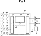
- the electrically operated valves and the pump 42 are controlled by at least one electronic control unit, which is outlined in Figure 2. It includes at least a microcomputer 102, an input circuit 104, an output circuit 106 and a connecting these elements Bus system 108 for mutual data exchange.
- Input circuit 104 is lines 50 and 54 of FIG Brake pedal switch 24 and pedal travel sensor 26 supplied. Further input lines 118 through 124 connect the input circuit 104 with the sensors assigned to each wheel brake 30 to 36.
- An input line 140 is also provided, that of the measuring device 46 for detecting the storage pressure is fed to the input line 104.
- Other input lines 126 to 128 connect the input circuit 104 with measuring devices 130 to 132 for detecting further Operating parameters of the brake system, the vehicle and / or its Drive unit.
- Such operating sizes are, for example the wheel speeds, possibly that of the engine torque, axle loads, the Pressure in the brake line (sensor 28), etc.
- To the output circuit 106 several output lines are connected. The output lines are shown by way of example which the valves of the pressure modulators are operated.
- the pump 42 is controlled via a further output line 138.
- the control unit 100 controls the brake system depending on of the supplied signal quantities in the above Senses.
- FIG 3 is a preferred embodiment for the determination individual error states in the area of pressure modulation or the components performing the pressure modulation shown.
- the flow chart represents the situation when monitoring a wheel brake. For the others The vehicle's wheel brakes will have a corresponding program run through or the outlined program one after the other run through for each wheel brake.
- Step 202 becomes the allowable deviation ⁇ from target and Actual pressure is determined, its value according to the dynamics of the Pressure regulator is fixed.
- Target pressure, actual pressure and / or storage pressure according to maps, characteristic curve, tables and / or Calculation steps taken into account.
- the difference between actual pressure and accumulator pressure is also used.
- a target gradient i.e.
- step 204 a target change of the storage pressure over time dPSPSOLL / dt formed from the pulse duty factor of the pump motor control signal and based on the current and a previous one Storage pressure PSP the storage pressure change over time dPSP / dt determined. It is then checked in step 204 whether braking is taking place or not. It will checks whether the setpoint PRADSOLL is the same for this wheel Is zero. If this is the case, there is no braking, so that it is checked according to step 206 whether the deviation between measured brake pressure PRADIST and target pressure PRADSOLL is greater than the permissible deviation.
- step 208 it is checked in step 208 whether the storage pressure change is less than the negative Setpoint is (rapid storage pressure drop). Is this the If so, an "Error1" is recognized. This shows an unwanted Pressure increase in the corresponding wheel in the state "No braking request" on, being a faulty component severely leaky or open inlet valve must be isolated can.
- Error2 If the change in accumulator pressure is not less than the negative setpoint, "Error2" is assumed. This The fault can be caused by the wheel pressure sensor indicates a faulty pressure or that heating and expansion of the brake fluid in an enclosed Space, with respect to the front wheel valves, by a non-opening Isolation valve, a non-opening temperature compensation valve or a blocked line, in the case of Rear axle braking through a non-opening relief or Balance valve or a blocked line took place Has. In hydraulic systems with normally open exhaust valves the relief valves can be omitted. Then the fault pattern is a non-opening exhaust valve instead a non-opening relief valve. A distinction These error conditions are determined based on the selection of the suitable emergency braking operation shown in Figure 4.
- step 214 the change in accumulator pressure above the Time ⁇ PSP with a target change dependent on the radist pressure ⁇ PSPSOLL compared. If the change is greater than the allowable Change, i.e. becomes a too large drop in storage pressure at a certain wheel brake pressure is found as Error "Error10" set. This indicates air in one or several wheel tongs. The program is then ended.
- Step 204 has resulted in a driver braking request or the system (e.g. FDR, ASR, ACC, ...) (Target brake pressure is not zero), so in step 218 checks whether there is a pressure build-up phase, i.e. if this corresponding inlet valve is controlled. Is this the Fall, in step 220 the Radistdruck with the target pressure compared (see also description of step 206). Is the Deviation of the actual pressure from the target pressure is less than the permissible Value, it is checked in step 222 whether the build time TAUFBAU exceeded a predetermined maximum time TMAX has (for example 2 seconds) and whether the storage pressure drop a predetermined limit, for example 30 bar / sec (rapid descent).
- step 224 it will set "Error3" according to step 224. This means that corresponding relief valve or exhaust valve is leaking or is open, or that there is a leak in the area of the brake system occurred between the memory and the media burner is. If one of the conditions in step 222 does not exist before, it is checked according to step 226 whether the deviation between wheel brake pressure and target wheel pressure less than the permissible Value on all wheels of the vehicle. this happens based on appropriate brands. Is that the case, “Step 4" is assumed in accordance with step 228. This leaves up close an error in the pressure supply. Kick this Fault pattern not on all wheels of the vehicle, but on according to step 230 only on the front axle wheels, so "Error 5" (step 232) accepted.
- step 234 "Error6". This error can in a non-opening inlet valve, in a leakage between Media separator and wheel tongs, in one non-moving Media separator, a blocked line, a leak or open temperature compensation valve or in a defective pressure sensor.
- step 220 After steps 224, 228, 232, 234 and in the case of a The no answer in step 220 continues with step 214.
- Step 218 has shown that there is no pressure build-up checked in step 236 whether pressure is being released. This happens based on a controlled exhaust valve. Is one Pressure reduction phase before, the control time T in step 238 if a maximum pressure reduction activation time is exceeded Tmax, e.g. 1 second, compared and the accumulator pressure gradient dPSP / dt compared with the target change. Exceeds the dismantling time is the maximum time and falls below the storage pressure gradient the negative setpoint (rapid degradation), "Error7" is set (step 240). This indicates that the inlet valve does not close.
- Tmax e.g. 1 second
- step 238 Is one of the conditions in If step 238 is not satisfied, the actual wheel brake pressure is reached in step 242 PRADIST and the wheel brake target pressure PRADSOLL to that effect compared whether the difference between the actual brake pressure and the target brake pressure is greater than the permissible value (see also description of step 206). If so, and this event occurs on all four wheels according to step 244 "error 9" is assumed in accordance with step 246. Everyone four wheels cannot reduce the pressure to zero bar take place, so that it can be assumed that the fluid level in the Storage container is too high or the return line to the container is clogged.
- step 242 The situation checked in step 242 does not occur at all four wheels, "error 8" is assumed according to step 248. This can be caused by a non-opening exhaust valve, a hanging media separator, a non-opening temperature compensation valve and / or a defective pressure sensor to have.
- step 240 246, 248 or in the case of one No answer in steps 242 and 236 continues with step 214.
- front axle and rear axle brakes are as follows Partial shutdown options. Firstly, with open ones Balance valves on the front and / or rear axle braked become. Furthermore, on a front wheel with muscle power operation be braked while the remaining three Wheels of the vehicle braked with electronic pressure control become. Braking in 3-wheel EMS operation is also possible done in which there is no pressure on one wheel of the front axle is built up and the balance valve of the front axle is closed becomes. Braking with open balance valves on an axis is then in the preferred embodiment performed if, for example, one of the two pressure sensors one axis fails.
- This axis will then be open Balance valve pressurized and pressure control regulated on the basis of the remaining pressure sensor. Since it is no longer possible to regulate the bike individually, bike-specific functions are switched off. The corresponding The procedure has been followed even when the body valve does not open proven suitable. Braking over muscle power on one wheel and electrical control on the remaining three wheels comes into consideration if For example, a media separator cannot be moved. The The wheel to which this media burner is assigned is the driver operated via the master cylinder, the remaining three wheels are still regulated in electrohydraulic operation. A 3-wheel EMS operation is initiated, for example, if there is a leak in a front brake circuit is sensed. Then the balance valve of the front axle closed and the corresponding wheel no longer with pressure provided. The de-energized closed dismantling valve of this bike is briefly activated at regular intervals. In order to avoid a strong build-up of yaw moment, one is Yaw moment limitation, its basic mode of operation is known from the prior art, advantageous.
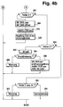
- Figure 4 is a detailed representation of the initiated Emergency braking operations depending on the respective fault shown on a preferred embodiment.
- the program outlined runs during the operating cycle at predetermined times.
- step 300 it is checked whether error 1, error 4 or error 9 is present. If this is the case, one is electronic regulated operation not possible.
- the system works in the fully hydraulic backup, all solenoid valves are de-energized (see illustration according to FIG. 1). This is the case with a leaky or open inlet valve, at Pressure supply error or too high Fluid level.
- a predetermined time is preferably 1 second, waited and then in step 312 gone in the purely hydraulic backup in which all Solenoid valves are dead. After that, the program is the same as in the case of continuous braking.
- step 314 checks whether Error3 is present. If this is the case, then in step 316 Traction control and driving dynamics control switched off, according to step 318, the inlet valve is de-energized and the exhaust valve at certain time intervals briefly controlled and according to step 320 a 3-wheel EMS control performed with the remaining 3 wheel brakes be electronically regulated. The anti-lock protection function remains active. The program is then ended.
- Step 322 checks if there is none when the exhaust valve is open Pressure reduction is measurable. If this is the case, according to Step 326 the appropriate balance and if necessary Relief valve opened. Then in step 328 checks whether a pressure reduction can now be measured. Is this is the case, it can be assumed that the exhaust valve does not open. In this case, according to step 330, the in Steps 316 through 320 illustrated 3-wheel EMS operation initiated. If no pressure reduction can be measured, the Step 332 opened the temperature compensation valve. in the subsequent step 334 checks whether there is now a Pressure reduction is measurable.
- Step 336 no reactions are initiated, since an error is detected during the next braking process, at which there is no pressure build-up in the wheel. Is in Step 334 no pressure reduction is recognized, so in Step 338 the known 3-wheel EMS operation is initiated. Has Step 324 indicate that no pressure reduction phase is active, i.e. an error detection took place after the pressure reduction phase according to step 340, no error is assumed and the pressure across the master cylinder by opening the isolation valves reduced. After steps 330, 336 and 338 and 340 the program is ended.
- Step 342 a check is carried out in accordance with step 342, whether error 6 is present. If this is the case, then according to Step 344 the balance valve of the front axle or that of the Open rear axle (depending on the fault location), according to step 346 ABS, traction control and driving dynamics control switched off and according to step 348 the control of the axis performed via a single pressure control loop. After that the program is ended.
- step 350 a check is carried out in accordance with step 350, whether error 2 was detected. If so, be according to step 352, the exhaust valves are opened and in step 354 checks whether a pressure change has taken place. Is if this is the case, it can be assumed that an enclosed one Volume is present because of relief or balance valves are not open. In this case, according to Step 356 just warned. If there is no pressure change, a pressure sensor offset error will be assumed. Therefore, according to step 358, the balance valve is opened and the pressure measurement is carried out via another wheel pressure sensor. Additional functions such as ABS, ASR or FDR are switched off. After step 356 or 358, the program is ended. If error 2 is also not present, step 360 is followed checks whether error 5 or 10 is present. Is that the case, is the driver acc. Warning step 362, otherwise find normal operation takes place after step 364.
Landscapes
- Engineering & Computer Science (AREA)
- Transportation (AREA)
- Mechanical Engineering (AREA)
- Physics & Mathematics (AREA)
- Fluid Mechanics (AREA)
- Regulating Braking Force (AREA)
- Valves And Accessory Devices For Braking Systems (AREA)
- Braking Systems And Boosters (AREA)
Abstract
Description
Claims (17)
- Verfahren zur Steuerung einer Bremsanlage eines Kraftfahrzeugs, bei welchem eine Bremsvorgabe in Sollradbremsdrücke für die einzelnen Radbremsen umgesetzt wird und der Radbremsdruck unter Berücksichtigung des gemessenen Radbremsdrucks auf den Sollradbremsdruck eingeregelt wird, dadurch gekennzeichnet, daß ein Notbremsbetrieb eingeleitet wird, wenn bei Nichtvorliegen eines Bremswunschs oder bei einem Druckaufbau der Druck in einem Rad vom Solldruck unzulässig abweicht, und dieser Notbremsbetrieb darin besteht, daß die Drucksteuerung an diesem Rad mit dem anderen Rad der gleichen Achse in einem Druckregelkreis erfolgt.
- Verfahren zur Steuerung einer Bremsanlage eines Kraftfahrzeugs, bei welchem eine Bremsvorgabe in Sollradbremsdrücke für die einzelnen Radbremsen umgesetzt wird und der Radbremsdruck unter Berücksichtigung des gemessenen Radbremsdrucks auf den Sollradbremsdruck eingeregelt wird, insbesondere nach Anspruch 1, dadurch gekennzeichnet, daß ein Notbremsbetrieb eingeleitet wird, wenn bei einem länger als eine bestimmte Zeit andauernden Druckaufbau der Druck in einem Rad vom Solldruck unzulässig abweicht oder wenn beim Druckabbau der Druck in einem Rad vom Solldruck unzulässig abweicht, und dieser Notbremsbetrieb darin besteht, daß das betroffene Rad nicht mehr geregelt wird und vom Hauptzylinder abgetrennt wird, während der verbliebenen Räder weiterhin geregelt werden.
- Verfahren zur Steuerung einer Bremsanlage eines Kraftfahrzeugs, bei welchem eine Bremsvorgabe in Sollradbremsdrücke für die einzelnen Radbremsen umgesetzt wird und der Radbremsdruck unter Berücksichtigung des gemessenen Radbremsdrucks auf den Sollradbremsdruck eingeregelt wird, insbesondere nach einem der vorhergehenden Ansprüche, dadurch gekennzeichnet, daß ein Notbremsbetrieb eingeleitet wird, wenn bei Nichtvorliegen eines Bremswunschs oder bei einem Druckaufbau der Druck in einem Rad vom Solldruck unzulässig abweicht und wenn zusätzlich beim Druckaufbau der Speicherdruckabfall einen vorgegebenen Grenzwert unterschreitet, oder wenn bei einem Druckaufbau oder -abbau der Druck in allen Rädern von den Solldrücken unzulässig abweicht oder wenn beim einem länger als eine bestimmte Zeit andauernder Druckabbau der Speicherdruck unzulässig abfällt, und dieser Notbremsbetrieb darin besteht, daß die Ventilanordnungen derart gesteuert werden, daß der Fahrer zumindest zu den Vorderachsbremsen einen hydraulischen Durchgriff hat.
- Verfahren zur Steuerung einer Bremsanlage eines Kraftfahrzeugs, bei welchem eine Bremsvorgabe in Sollradbremsdrücke für die einzelnen Radbremsen umgesetzt wird und der Radbremsdruck unter Berücksichtigung des gemessenen Radbremsdrucks auf den Sollradbremsdruck eingeregelt wird, insbesondere nach einem der vorhergehenden Ansprüche, dadurch gekennzeichnet, daß kein Notbremsbetrieb eingeleitet wird und der Fahrer lediglich gewarnt wird, wenn bei einem Druckaufbau der Druck in beiden Vorderrädern von den Solldrücken unzulässig abweicht oder wenn der Speicherdruckabfall größer als ein raddruckabhängiger Grenzwert ist.
- Verfahren nach Anspruch 1, daß dieser Notbremsbetrieb nur dann eingeleitet wird, wenn zusätzlich beim Rad-Druckaufbau der Speicherdruckabfall einen vorgegebenen Grenzwert nicht unterschreitet.
- Verfahren nach Anspruch 1 oder 5, dadurch gekennzeichnet, daß dieser Notbremsbetrieb durch Öffnen des der Achse zugeordneten Balanceventils erfolgt.
- Verfahren nach Anspruch 1, 5 oder 6, dadurch gekennzeichnet, daß bei diesem Notbremsbetrieb radindividuelle Funktionen der betroffenen Achse abgeschaltet werden, während zumindest die ABS-Funktion an der anderen Achse erhalten bleibt.
- Verfahren nach Anspruch 1, 5, 6 oder 7, dadurch gekennzeichnet, daß, wenn bei Nichtvorliegen eines Bremswunschs oder bei einem Druckaufbau der Druck in einem Rad vom Solldruck unzulässig abweicht, die Ventilanordnung im Sinne eines Druckabbaus an diesem Rad angesteuert wird, wobei der Notbremsbetrieb nur dann eingeleitet wird, wenn keine Druckänderung erkannt wird.
- Verfahren nach Anspruch 2, dadurch gekennzeichnet, daß bei diesem Notbremsbetrieb radindividuelle Funktionen der betroffenen Achse abgeschaltet werden, während zumindest die ABS-Funktion an der anderen Achse erhalten bleibt.
- Verfahren nach Anspruch 2 oder 9, dadurch gekennzeichnet, daß während des Notbremsbetriebs die Ventilanordnung des betroffenen Rades zeitabhängig im Sinne eines Druckabbaus angesteuert wird.
- Verfahren nach Anspruch 2, 9 oder 10, dadurch gekennzeichnet, daß zur Vermeidung eines starken Giermomentenaufbau eine Giermomentenabschwächung vorgesehen ist.
- Verfahren nach Anspruch 2, 9, 10 oder 11, dadurch gekennzeichnet, daß Antriebsschlupfregler bzw. Fahrdynamikregler abgeschaltet werden während der Antiblockierregler aktiv bleibt.
- Verfahren nach einem der vorhergehenden Ansprüche, dadurch gekennzeichnet, daß die Fehlerermittlung auch dann aktiv ist, wenn bereits ein Fehler erkannt wurde und das System sich nicht im rein hydraulischen Notbremsbetrieb befindet.
- Vorrichtung zur Steuerung einer Bremsanlage eines Kraftfahrzeugs, mit einer Steuereinheit, welche eine Bremsvorgabe in Sollradbremsdrücke für die einzelnen Radbremsen umsetzt und die den Radbremsdruck unter Berücksichtigung des gemessenen Radbremsdrucks auf den Sollradbremsdruck einregelt, dadurch gekennzeichnet, daß die Steuereinheit Mittel enthält, die einen Notbremsbetrieb einleiten, wenn bei Nichtvorliegen eines Bremswunschs oder bei einem Druckaufbau der Druck in einem Rad vom Solldruck unzulässig abweicht, wobei dieser Notbremsbetrieb darin besteht, daß die Drucksteuerung an diesem Rad mit dem anderen Rad der gleichen Achse in einem Druckregelkreis erfolgt.
- Vorrichtung zur Steuerung einer Bremsanlage eines Kraftfahrzeugs, mit einer Steuereinheit, welche eine Bremsvorgabe in Sollradbremsdrücke für die einzelnen Radbremsen umsetzt und die den Radbremsdruck unter Berücksichtigung des gemessenen Radbremsdrucks auf den Sollradbremsdruck einregelt, insbesondere nach Anspruch 17, dadurch gekennzeichnet, daß die Steuereinheit Mittel enthält, die einen Notbremsbetrieb einleiten, wenn bei einem länger als eine bestimmte Zeit andauerndem Druckaufbau der Druck in einem Rad vom Solldruck unzulässig abweicht oder wenn beim Druckabbau der Druck in einem Rad vom Solldruck unzulässig abweicht, wobei dieser Notbremsbetrieb darin besteht, daß das betroffene Rad nicht mehr geregelt wird und vom Hauptzylinder abgetrennt wird, während der verbliebenen Räder weiterhin geregelt werden.
- Vorrichtung zur Steuerung einer Bremsanlage eines Kraftfahrzeugs, mit einer Steuereinheit, welche eine Bremsvorgabe in Sollradbremsdrücke für die einzelnen Radbremsen umsetzt und die den Radbremsdruck unter Berücksichtigung des gemessenen Radbremsdrucks auf den Sollradbremsdruck einregelt, insbesondere nach einem der vorhergehenden Ansprüche, dadurch gekennzeichnet, daß die Steuereinheit Mittel enthält, die einen Notbremsbetrieb einleiten, wenn bei Nichtvorliegen eines Bremswunschs oder bei einem Druckaufbau der Druck in einem Rad vom Solldruck unzulässig abweicht und wenn zusätzlich beim Druckaufbau der Speicherdruckabfall einen vorgegebenen Grenzwert unterschreitet, oder wenn bei einem Druckaufbau oder -abbau der Druck in allen Rädern von den Solldrücken unzulässig abweicht oder wenn bei einem länger als eine bestimmte Zeit andauernden Druckabbau der Speicherdruck unzulässig abfällt, wobei dieser Notbremsbetrieb darin besteht, daß die Ventilanordnungen derart gesteuert werden, daß der Fahrer zumindest zu den Vorderachsbremsen einen hydraulischen Durchgriff hat.
- Vorrichtung zur Steuerung einer Bremsanlage eines Kraftfahrzeugs, mit einer Steuereinheit, welche eine Bremsvorgabe in Sollradbremsdrücke für die einzelnen Radbremsen umsetzt und die den Radbremsdruck unter Berücksichtigung des gemessenen Radbremsdrucks auf den Sollradbremsdruck einregelt, insbesondere nach einem der vorhergehenden Ansprüche, dadurch gekennzeichnet, daß die Steuereinheit Mittel enthält, die einen Notbremsbetrieb einleiten, die keinen Notbremsbetrieb einleiten und die den Fahrer lediglich warnen, wenn bei einem Druckaufbau der Druck in beiden Vorderrädern von den Solldrücken unzulässig abweicht oder wenn der Speicherdruckabfall größer als ein raddruckabhängiger Grenzwert ist.
Applications Claiming Priority (2)
| Application Number | Priority Date | Filing Date | Title |
|---|---|---|---|
| DE19807366A DE19807366A1 (de) | 1998-02-21 | 1998-02-21 | Verfahren und Vorrichtung zur Steuerung einer Bremsanlage |
| DE19807366 | 1998-02-21 |
Publications (3)
| Publication Number | Publication Date |
|---|---|
| EP0937617A2 true EP0937617A2 (de) | 1999-08-25 |
| EP0937617A3 EP0937617A3 (de) | 2002-03-20 |
| EP0937617B1 EP0937617B1 (de) | 2006-07-12 |
Family
ID=7858523
Family Applications (1)
| Application Number | Title | Priority Date | Filing Date |
|---|---|---|---|
| EP98118807A Expired - Lifetime EP0937617B1 (de) | 1998-02-21 | 1998-10-05 | Verfahren und Vorrichtung zur Steuerung einer Bremsanlage |
Country Status (4)
| Country | Link |
|---|---|
| US (1) | US6249736B1 (de) |
| EP (1) | EP0937617B1 (de) |
| JP (1) | JP4390892B2 (de) |
| DE (2) | DE19807366A1 (de) |
Cited By (6)
| Publication number | Priority date | Publication date | Assignee | Title |
|---|---|---|---|---|
| WO2001062567A1 (en) * | 2000-02-25 | 2001-08-30 | Westinghouse Brakes (Uk) Limited | Controlling pressure in brake actuation outputs |
| EP1004494A3 (de) * | 1998-11-27 | 2002-04-10 | LUCAS INDUSTRIES public limited company | Erkennung und Identifizierung von Drucksensorfehlern in elektrohydraulischen Bremsanlagen |
| WO2002042138A1 (de) * | 2000-11-27 | 2002-05-30 | Continental Teves Ag & Co. Ohg | Verfahren zur steuerung einer elektrohydraulischen bremsanlage |
| EP1288095A3 (de) * | 2001-08-31 | 2003-07-16 | Günther Dipl.-Ing.(TU) Winkle | Bremsdiagnose für Schienen- und Strassenfahrzeuge |
| EP1808348A1 (de) * | 2006-01-12 | 2007-07-18 | Knorr-Bremse Systeme für Schienenfahrzeuge GmbH | Verschliessarme und genaue Druckregelung mit Schaltventilen zur Bremsdruckregelung in Schienenfahrzeugen |
| WO2017097797A1 (de) * | 2015-12-10 | 2017-06-15 | Knorr-Bremse Systeme für Nutzfahrzeuge GmbH | Verfahren zur detektion und kompensation einer leckage in einer bremsvorrichtung |
Families Citing this family (38)
| Publication number | Priority date | Publication date | Assignee | Title |
|---|---|---|---|---|
| GB2347981B (en) * | 1999-03-05 | 2003-01-22 | Lucas Industries Ltd | Electro-hydraulic braking systems |
| DE19952781A1 (de) * | 1999-11-03 | 2001-06-13 | Daimler Chrysler Ag | Verfahren zum Abbremsen eines Fahrzeugs |
| JP4543476B2 (ja) * | 2000-02-14 | 2010-09-15 | トヨタ自動車株式会社 | ブレーキ装置 |
| DE50113756D1 (de) * | 2000-03-27 | 2008-04-30 | Continental Teves Ag & Co Ohg | Bremsanlage für kraftfahrzeuge |
| DE10033909B4 (de) * | 2000-07-12 | 2009-11-19 | Robert Bosch Gmbh | Verfahren und Vorrichtung zur Steuerung wenigstens eines Ventils |
| DE10036287B4 (de) * | 2000-07-26 | 2009-07-30 | Robert Bosch Gmbh | Verfahren und Vorrichtung zur Steuerung von Radbremsen |
| EP1339581A1 (de) | 2000-11-21 | 2003-09-03 | Continental Teves AG & Co. oHG | Verfahren zum betreiben eines elektronisch regelbaren bremsbetätigungssystems |
| JP3941388B2 (ja) * | 2000-12-21 | 2007-07-04 | トヨタ自動車株式会社 | 車輌の制動制御装置 |
| JP2002356158A (ja) * | 2001-05-30 | 2002-12-10 | Toyota Motor Corp | 車輌用制動制御装置 |
| JP2003127849A (ja) * | 2001-10-26 | 2003-05-08 | Aisin Seiki Co Ltd | 車両用液圧ブレーキ装置 |
| DE10214456A1 (de) | 2002-03-30 | 2003-10-30 | Bosch Gmbh Robert | Verfahren und Vorrichtung zur Überwachung einer Bremsanlage |
| US7013209B2 (en) | 2003-06-16 | 2006-03-14 | Delphi Technologies, Inc. | Operating a multimode ABS |
| JP4506121B2 (ja) * | 2003-07-25 | 2010-07-21 | トヨタ自動車株式会社 | 車輌の制動力制御装置 |
| KR20050116351A (ko) * | 2005-09-09 | 2005-12-12 | 정보문 | Abs와 복합제어 되는 유압식 주차브레이크 자동제어장치 및제어방법 |
| EP1937528B1 (de) * | 2005-10-12 | 2010-12-15 | Continental Teves AG & Co. oHG | Bremsanlage für kraftfahrzeuge |
| US7475953B2 (en) * | 2006-02-03 | 2009-01-13 | Kelsey-Hayes Company | Soft-stop braking control |
| JP4492675B2 (ja) * | 2006-11-08 | 2010-06-30 | トヨタ自動車株式会社 | 車両用制動装置 |
| JP5014916B2 (ja) * | 2007-08-10 | 2012-08-29 | 日立オートモティブシステムズ株式会社 | ブレーキ制御装置 |
| JP5014919B2 (ja) | 2007-08-17 | 2012-08-29 | 日立オートモティブシステムズ株式会社 | ブレーキ制御装置 |
| DE102009045714A1 (de) * | 2009-04-28 | 2010-11-04 | Continental Teves Ag & Co. Ohg | Schlupfgeregelte hydraulische Fahrzeugbremsanlage |
| KR101673046B1 (ko) * | 2009-08-24 | 2016-11-16 | 켈시-헤이즈 컴파니 | 차량 제동 시스템용 감쇠기 |
| US8433491B2 (en) | 2010-10-12 | 2013-04-30 | Toyota Motor Engineering & Manufacturing North America, Inc. | Electromechanical deceleration system and method for operating the same |
| TWI421177B (zh) * | 2011-03-18 | 2014-01-01 | 財團法人工業技術研究院 | 節能控制方法與系統 |
| DE102013216157A1 (de) * | 2012-09-28 | 2014-04-03 | Continental Teves Ag & Co. Ohg | Verfahren zur Regelung einer Bremsanlage für Kraftfahrzeuge |
| DE102012020010A1 (de) * | 2012-10-12 | 2014-04-17 | Volkswagen Aktiengesellschaft | Verfahren zur Steuerung eines Bremssystems |
| US20140346854A1 (en) * | 2013-05-23 | 2014-11-27 | Caterpillar Global Mining Llc | Braking system |
| DE102013015162A1 (de) * | 2013-09-11 | 2015-03-12 | GM Global Technology Operations LLC (n. d. Gesetzen des Staates Delaware) | Vorrichtung zur Steuerung eines Hydraulikbremssystems eines Fahrzeugs |
| KR102115716B1 (ko) * | 2013-10-07 | 2020-05-27 | 현대모비스 주식회사 | 전자식 유압 브레이크장치 |
| KR101901782B1 (ko) * | 2013-11-14 | 2018-09-28 | 주식회사 만도 | 유압 제동 장치 및 그 제어방법 |
| DE102014006584A1 (de) * | 2014-05-03 | 2015-11-05 | Audi Ag | Verfahren zum Erkennen eines Fehlverbaus von Bremsleitungen |
| KR102016381B1 (ko) * | 2014-12-30 | 2019-10-21 | 주식회사 만도 | 전자식 브레이크 시스템 |
| KR102353022B1 (ko) | 2017-05-17 | 2022-01-20 | 주식회사 만도 | 전자식 브레이크 시스템 |
| DE102017213392A1 (de) * | 2017-08-02 | 2019-02-07 | Robert Bosch Gmbh | Steuervorrichtung und Verfahren zum Betreiben eines Simulator-bestückten hydraulischen Bremssystems eines Fahrzeugs |
| CN109606344B (zh) * | 2018-11-27 | 2021-01-15 | 江苏大学 | 一种拖挂式房车电磁制动器制动故障检测警报与处理系统及其控制方法 |
| DE202019101596U1 (de) | 2019-02-12 | 2020-05-13 | Ipgate Ag | Hydrauliksystem mit mindestens zwei hydraulischen Kreisen und mindestens zwei Druckversorgungseinrichtungen |
| CN113631443B (zh) | 2019-02-12 | 2024-02-23 | 爱皮加特股份公司 | 具有压力供给装置和用于制动回路的安全门的制动系统 |
| DE202019101586U1 (de) | 2019-02-12 | 2020-05-13 | Ipgate Ag | Packaging für ein Bremssystem |
| DE102019103464A1 (de) * | 2019-02-12 | 2020-08-13 | Ipgate Ag | Hydrauliksystem mit mindestens zwei hydraulischen Kreisen und mindestens zwei Druckversorgungseinrichtungen |
Family Cites Families (28)
| Publication number | Priority date | Publication date | Assignee | Title |
|---|---|---|---|---|
| DE3412233A1 (de) * | 1984-04-02 | 1985-10-10 | Robert Bosch Gmbh, 7000 Stuttgart | Ueberwachungsverfahren fuer ein bremssystem |
| DE3418042A1 (de) * | 1984-05-15 | 1985-11-21 | Alfred Teves Gmbh, 6000 Frankfurt | Vorrichtung zur ueberwachung des hilfsenergie-druckes einer schlupfgeregelten bremsanlage |
| DE3630342C2 (de) * | 1986-09-05 | 1996-04-18 | Teves Gmbh Alfred | Verfahren zur Überwachung einer blockiergeschützten Bremsanlage |
| DE3829949A1 (de) * | 1988-09-03 | 1990-03-15 | Daimler Benz Ag | Verfahren zum betrieb einer elektrischen druckmittel-betriebsbremseinrichtung und steuervorrichtung zur durchfuehrung des verfahrens |
| JP3024225B2 (ja) * | 1991-01-23 | 2000-03-21 | トヨタ自動車株式会社 | 液圧発生装置の異常検出方法 |
| JP3205570B2 (ja) * | 1991-06-07 | 2001-09-04 | 本田技研工業株式会社 | 車両用制動装置 |
| JPH05310112A (ja) * | 1992-05-08 | 1993-11-22 | Mazda Motor Corp | 車両のブレ−キ装置 |
| JPH06115416A (ja) * | 1992-10-02 | 1994-04-26 | Nissan Motor Co Ltd | ブレーキ液圧制御装置 |
| JP3409805B2 (ja) * | 1993-06-30 | 2003-05-26 | 三菱自動車工業株式会社 | 車両用制動装置 |
| JP3253039B2 (ja) * | 1993-07-06 | 2002-02-04 | 日信工業株式会社 | 車両用制動装置 |
| DE4326919A1 (de) * | 1993-08-11 | 1995-02-16 | Teves Gmbh Alfred | Regelschaltung für Bremsanlagen mit ABS und/oder ASR |
| JPH07117644A (ja) * | 1993-10-25 | 1995-05-09 | Sumitomo Electric Ind Ltd | 車輌のブレーキシステム |
| DE4340467C2 (de) * | 1993-11-27 | 2002-03-14 | Bosch Gmbh Robert | Mit Fremdkraft arbeitende hydraulische Fahrzeugbremsanlage |
| DE4417935A1 (de) * | 1994-05-21 | 1995-11-23 | Teves Gmbh Alfred | Schaltungsanordnung für eine Bremsanlage mit elektronischer Regelung der Bremskraftverteilung |
| JPH08332936A (ja) * | 1995-06-07 | 1996-12-17 | Nissan Motor Co Ltd | 車両のブレーキ制御装置 |
| DE19537962A1 (de) * | 1995-10-12 | 1997-04-17 | Teves Gmbh Alfred | Elektronisch regelbares Bremsbetätigungssystem |
| DE19542654A1 (de) * | 1995-11-15 | 1997-05-22 | Lucas Ind Plc | Elektronische steuerbare Bremsanlage für Kraftfahrzeuge |
| JPH09142279A (ja) * | 1995-11-24 | 1997-06-03 | Aisin Seiki Co Ltd | ブレーキ液圧制御装置 |
| JPH09193781A (ja) * | 1995-12-30 | 1997-07-29 | Robert Bosch Gmbh | ブレーキ装置のモニタ装置 |
| JPH1035466A (ja) * | 1996-07-23 | 1998-02-10 | Toyota Motor Corp | ブレーキ液圧制御装置 |
| JPH10119740A (ja) * | 1996-10-18 | 1998-05-12 | Tokico Ltd | ブレーキ制御装置 |
| JP3753810B2 (ja) * | 1996-10-18 | 2006-03-08 | 株式会社日立製作所 | ブレーキ液圧制御装置 |
| JPH10181563A (ja) * | 1996-12-26 | 1998-07-07 | Unisia Jecs Corp | ブレーキ制御装置 |
| JPH10217936A (ja) * | 1997-02-10 | 1998-08-18 | Tokico Ltd | 車両用ブレーキ制御装置 |
| DE19706850B4 (de) * | 1997-02-21 | 2007-12-13 | Robert Bosch Gmbh | Verfahren und Vorrichtung zur Steuerung einer Bremsanlage eines Fahrzeugs |
| JPH10250560A (ja) * | 1997-03-12 | 1998-09-22 | Tokico Ltd | ブレーキ液圧制御装置 |
| JP3433786B2 (ja) * | 1997-07-08 | 2003-08-04 | トヨタ自動車株式会社 | 制動力制御装置 |
| JPH1159387A (ja) * | 1997-08-27 | 1999-03-02 | Toyota Motor Corp | 電動車両の制動装置 |
-
1998
- 1998-02-21 DE DE19807366A patent/DE19807366A1/de not_active Withdrawn
- 1998-10-05 DE DE59813637T patent/DE59813637D1/de not_active Expired - Lifetime
- 1998-10-05 EP EP98118807A patent/EP0937617B1/de not_active Expired - Lifetime
-
1999
- 1999-02-19 JP JP04090799A patent/JP4390892B2/ja not_active Expired - Fee Related
- 1999-02-19 US US09/253,602 patent/US6249736B1/en not_active Expired - Lifetime
Cited By (8)
| Publication number | Priority date | Publication date | Assignee | Title |
|---|---|---|---|---|
| EP1004494A3 (de) * | 1998-11-27 | 2002-04-10 | LUCAS INDUSTRIES public limited company | Erkennung und Identifizierung von Drucksensorfehlern in elektrohydraulischen Bremsanlagen |
| US6634221B2 (en) | 1998-11-27 | 2003-10-21 | Lucas Industries Plc | Detection and identification of pressure-sensor faults in electro-hydraulic (EHB) braking systems |
| WO2001062567A1 (en) * | 2000-02-25 | 2001-08-30 | Westinghouse Brakes (Uk) Limited | Controlling pressure in brake actuation outputs |
| WO2002042138A1 (de) * | 2000-11-27 | 2002-05-30 | Continental Teves Ag & Co. Ohg | Verfahren zur steuerung einer elektrohydraulischen bremsanlage |
| EP1288095A3 (de) * | 2001-08-31 | 2003-07-16 | Günther Dipl.-Ing.(TU) Winkle | Bremsdiagnose für Schienen- und Strassenfahrzeuge |
| EP1808348A1 (de) * | 2006-01-12 | 2007-07-18 | Knorr-Bremse Systeme für Schienenfahrzeuge GmbH | Verschliessarme und genaue Druckregelung mit Schaltventilen zur Bremsdruckregelung in Schienenfahrzeugen |
| WO2017097797A1 (de) * | 2015-12-10 | 2017-06-15 | Knorr-Bremse Systeme für Nutzfahrzeuge GmbH | Verfahren zur detektion und kompensation einer leckage in einer bremsvorrichtung |
| CN108602505A (zh) * | 2015-12-10 | 2018-09-28 | 克诺尔商用车制动系统有限公司 | 用于探测和补偿制动装置中的泄漏的方法 |
Also Published As
| Publication number | Publication date |
|---|---|
| DE59813637D1 (de) | 2006-08-24 |
| JP4390892B2 (ja) | 2009-12-24 |
| JPH11348751A (ja) | 1999-12-21 |
| US6249736B1 (en) | 2001-06-19 |
| EP0937617A3 (de) | 2002-03-20 |
| DE19807366A1 (de) | 1999-08-26 |
| EP0937617B1 (de) | 2006-07-12 |
Similar Documents
| Publication | Publication Date | Title |
|---|---|---|
| EP0937617B1 (de) | Verfahren und Vorrichtung zur Steuerung einer Bremsanlage | |
| EP0937618B1 (de) | Verfahren und Vorrichtung zur Überprüfung einer Bremsanlage | |
| EP0937621B1 (de) | Verfahren und Vorrichtung zur Steuerung einer Bremsanlage | |
| EP0937620B1 (de) | Verfahren und Vorrichtung zur Steuerung einer Bremsanlage | |
| EP0895502B1 (de) | Elektrohydraulische bremsanlage | |
| DE19603863B4 (de) | Verfahren und Vorrichtungen zur Überprüfung der Bremsanlage eines Fahrzeugs | |
| EP4103434A1 (de) | Fahrdynamiksystem, e-fahrzeug mit zentraler steuerung | |
| DE19732884C2 (de) | Vorrichtung zur Steuerung des Bremsfluiddrucks in einem Fahrzeugbremssystem | |
| DE102008014798A1 (de) | Bremsregelvorrichtung und Aufpumpsystem | |
| DE112009000327T5 (de) | Bremsanlage und Bremsregelungs-/Bremssteuerungsverfahren | |
| EP1339582A1 (de) | Verfahren zur steuerung einer elektrohydraulischen bremsanlage | |
| DE19729097B4 (de) | Verfahren und Vorrichtung zur Steuerung einer Bremsanlage | |
| EP0892732A1 (de) | Verfahren und vorrichtung zur steuerung der bremskraftverteilung bei einem kraftfahrzeug | |
| EP0937614B1 (de) | Verfahren und Vorrichtung zur Steuerung einer Bremsanlage | |
| DE19706850B4 (de) | Verfahren und Vorrichtung zur Steuerung einer Bremsanlage eines Fahrzeugs | |
| DE19603867A1 (de) | Verfahren und Vorrichtung zur Überprüfung der Bremsanlage eines Fahrzeugs | |
| EP1055576A2 (de) | Elektrohydraulisches Bremssystem und Verfahren zu seiner Steuerung | |
| DE69833404T2 (de) | Manuelle Hinterbremssteuerung für eine elektro-hydraulische Bremsanlage | |
| DE10147194A1 (de) | Verfahren zum Betreiben eines elektronisch regelbaren Bremsbetätigungssystems | |
| DE69616869T2 (de) | Elektronische Bremssysteme | |
| WO2021078997A1 (de) | Verfahren zum betreiben einer bremsanlage mit einer integrierten parkbremse und bremsanlage | |
| DE102007029228A1 (de) | Verfahren und System zur Ermittlung von Druckunterschieden in den Bremskreisen von Fahrzeugbremsanlagen | |
| WO2024012900A1 (de) | Verfahren zum bestimmen eines bremsdrucks und druckmittelbetätigte bremseinrichtung | |
| EP4731483A1 (de) | Verfahren zum betreiben eines bremssystems sowie bremssystem | |
| EP1419074A1 (de) | Verfahren zur prüfung eines stromreglers eines elektronisch ansteuerbaren ventils einer hydraulischen fahrzeugbremsanlage |
Legal Events
| Date | Code | Title | Description |
|---|---|---|---|
| PUAI | Public reference made under article 153(3) epc to a published international application that has entered the european phase |
Free format text: ORIGINAL CODE: 0009012 |
|
| AK | Designated contracting states |
Kind code of ref document: A2 Designated state(s): AT BE CH CY DE DK ES FI FR GB GR IE IT LI LU MC NL PT SE Kind code of ref document: A2 Designated state(s): DE FR GB |
|
| AX | Request for extension of the european patent |
Free format text: AL;LT;LV;MK;RO;SI |
|
| PUAL | Search report despatched |
Free format text: ORIGINAL CODE: 0009013 |
|
| AK | Designated contracting states |
Kind code of ref document: A3 Designated state(s): AT BE CH CY DE DK ES FI FR GB GR IE IT LI LU MC NL PT SE |
|
| AX | Request for extension of the european patent |
Free format text: AL;LT;LV;MK;RO;SI |
|
| RIC1 | Information provided on ipc code assigned before grant |
Free format text: 7B 60T 8/88 A, 7B 60T 13/66 B, 7G 05B 9/02 B, 7B 60T 13/74 B, 7B 60T 7/04 B |
|
| 17P | Request for examination filed |
Effective date: 20020920 |
|
| AKX | Designation fees paid |
Free format text: DE FR GB |
|
| GRAP | Despatch of communication of intention to grant a patent |
Free format text: ORIGINAL CODE: EPIDOSNIGR1 |
|
| RIN1 | Information on inventor provided before grant (corrected) |
Inventor name: GOTTWICK, ULRICH Inventor name: WINNER, HERMANN Inventor name: BINDER, JUERGEN Inventor name: SCHMIDT, GUENTHER |
|
| GRAS | Grant fee paid |
Free format text: ORIGINAL CODE: EPIDOSNIGR3 |
|
| GRAA | (expected) grant |
Free format text: ORIGINAL CODE: 0009210 |
|
| AK | Designated contracting states |
Kind code of ref document: B1 Designated state(s): DE FR GB |
|
| REG | Reference to a national code |
Ref country code: GB Ref legal event code: FG4D Free format text: NOT ENGLISH |
|
| REF | Corresponds to: |
Ref document number: 59813637 Country of ref document: DE Date of ref document: 20060824 Kind code of ref document: P |
|
| GBT | Gb: translation of ep patent filed (gb section 77(6)(a)/1977) |
Effective date: 20061018 |
|
| ET | Fr: translation filed | ||
| PLBE | No opposition filed within time limit |
Free format text: ORIGINAL CODE: 0009261 |
|
| STAA | Information on the status of an ep patent application or granted ep patent |
Free format text: STATUS: NO OPPOSITION FILED WITHIN TIME LIMIT |
|
| 26N | No opposition filed |
Effective date: 20070413 |
|
| PGFP | Annual fee paid to national office [announced via postgrant information from national office to epo] |
Ref country code: FR Payment date: 20121113 Year of fee payment: 15 |
|
| PGFP | Annual fee paid to national office [announced via postgrant information from national office to epo] |
Ref country code: GB Payment date: 20121023 Year of fee payment: 15 |
|
| REG | Reference to a national code |
Ref country code: DE Ref legal event code: R084 Ref document number: 59813637 Country of ref document: DE Effective date: 20130603 |
|
| GBPC | Gb: european patent ceased through non-payment of renewal fee |
Effective date: 20131005 |
|
| PG25 | Lapsed in a contracting state [announced via postgrant information from national office to epo] |
Ref country code: GB Free format text: LAPSE BECAUSE OF NON-PAYMENT OF DUE FEES Effective date: 20131005 |
|
| REG | Reference to a national code |
Ref country code: FR Ref legal event code: ST Effective date: 20140630 |
|
| PG25 | Lapsed in a contracting state [announced via postgrant information from national office to epo] |
Ref country code: FR Free format text: LAPSE BECAUSE OF NON-PAYMENT OF DUE FEES Effective date: 20131031 |
|
| PGFP | Annual fee paid to national office [announced via postgrant information from national office to epo] |
Ref country code: DE Payment date: 20161213 Year of fee payment: 19 |
|
| REG | Reference to a national code |
Ref country code: DE Ref legal event code: R119 Ref document number: 59813637 Country of ref document: DE |
|
| PG25 | Lapsed in a contracting state [announced via postgrant information from national office to epo] |
Ref country code: DE Free format text: LAPSE BECAUSE OF NON-PAYMENT OF DUE FEES Effective date: 20180501 |