EP0950803A2 - Dispositif de purification de gaz d'échappement d'un moteur à combustion interne - Google Patents
Dispositif de purification de gaz d'échappement d'un moteur à combustion interne Download PDFInfo
- Publication number
- EP0950803A2 EP0950803A2 EP99107288A EP99107288A EP0950803A2 EP 0950803 A2 EP0950803 A2 EP 0950803A2 EP 99107288 A EP99107288 A EP 99107288A EP 99107288 A EP99107288 A EP 99107288A EP 0950803 A2 EP0950803 A2 EP 0950803A2
- Authority
- EP
- European Patent Office
- Prior art keywords
- fuel ratio
- air
- exhaust
- way catalyst
- sox
- Prior art date
- Legal status (The legal status is an assumption and is not a legal conclusion. Google has not performed a legal analysis and makes no representation as to the accuracy of the status listed.)
- Granted
Links
Images


Classifications
-
- F—MECHANICAL ENGINEERING; LIGHTING; HEATING; WEAPONS; BLASTING
- F02—COMBUSTION ENGINES; HOT-GAS OR COMBUSTION-PRODUCT ENGINE PLANTS
- F02D—CONTROLLING COMBUSTION ENGINES
- F02D41/00—Electrical control of supply of combustible mixture or its constituents
- F02D41/008—Controlling each cylinder individually
- F02D41/0082—Controlling each cylinder individually per groups or banks
-
- B—PERFORMING OPERATIONS; TRANSPORTING
- B01—PHYSICAL OR CHEMICAL PROCESSES OR APPARATUS IN GENERAL
- B01D—SEPARATION
- B01D53/00—Separation of gases or vapours; Recovering vapours of volatile solvents from gases; Chemical or biological purification of waste gases, e.g. engine exhaust gases, smoke, fumes, flue gases, aerosols
- B01D53/34—Chemical or biological purification of waste gases
- B01D53/92—Chemical or biological purification of waste gases of engine exhaust gases
- B01D53/94—Chemical or biological purification of waste gases of engine exhaust gases by catalytic processes
- B01D53/9495—Controlling the catalytic process
-
- F—MECHANICAL ENGINEERING; LIGHTING; HEATING; WEAPONS; BLASTING
- F01—MACHINES OR ENGINES IN GENERAL; ENGINE PLANTS IN GENERAL; STEAM ENGINES
- F01N—GAS-FLOW SILENCERS OR EXHAUST APPARATUS FOR MACHINES OR ENGINES IN GENERAL; GAS-FLOW SILENCERS OR EXHAUST APPARATUS FOR INTERNAL-COMBUSTION ENGINES
- F01N13/00—Exhaust or silencing apparatus characterised by constructional features
- F01N13/009—Exhaust or silencing apparatus characterised by constructional features having two or more separate purifying devices arranged in series
-
- F—MECHANICAL ENGINEERING; LIGHTING; HEATING; WEAPONS; BLASTING
- F01—MACHINES OR ENGINES IN GENERAL; ENGINE PLANTS IN GENERAL; STEAM ENGINES
- F01N—GAS-FLOW SILENCERS OR EXHAUST APPARATUS FOR MACHINES OR ENGINES IN GENERAL; GAS-FLOW SILENCERS OR EXHAUST APPARATUS FOR INTERNAL-COMBUSTION ENGINES
- F01N13/00—Exhaust or silencing apparatus characterised by constructional features
- F01N13/011—Exhaust or silencing apparatus characterised by constructional features having two or more purifying devices arranged in parallel
-
- F—MECHANICAL ENGINEERING; LIGHTING; HEATING; WEAPONS; BLASTING
- F01—MACHINES OR ENGINES IN GENERAL; ENGINE PLANTS IN GENERAL; STEAM ENGINES
- F01N—GAS-FLOW SILENCERS OR EXHAUST APPARATUS FOR MACHINES OR ENGINES IN GENERAL; GAS-FLOW SILENCERS OR EXHAUST APPARATUS FOR INTERNAL-COMBUSTION ENGINES
- F01N3/00—Exhaust or silencing apparatus having means for purifying, rendering innocuous, or otherwise treating exhaust
- F01N3/08—Exhaust or silencing apparatus having means for purifying, rendering innocuous, or otherwise treating exhaust for rendering innocuous
- F01N3/0807—Exhaust or silencing apparatus having means for purifying, rendering innocuous, or otherwise treating exhaust for rendering innocuous by using absorbents or adsorbents
- F01N3/0828—Exhaust or silencing apparatus having means for purifying, rendering innocuous, or otherwise treating exhaust for rendering innocuous by using absorbents or adsorbents characterised by the absorbed or adsorbed substances
- F01N3/0842—Nitrogen oxides
-
- F—MECHANICAL ENGINEERING; LIGHTING; HEATING; WEAPONS; BLASTING
- F02—COMBUSTION ENGINES; HOT-GAS OR COMBUSTION-PRODUCT ENGINE PLANTS
- F02D—CONTROLLING COMBUSTION ENGINES
- F02D41/00—Electrical control of supply of combustible mixture or its constituents
- F02D41/02—Circuit arrangements for generating control signals
- F02D41/021—Introducing corrections for particular conditions exterior to the engine
- F02D41/0235—Introducing corrections for particular conditions exterior to the engine in relation with the state of the exhaust gas treating apparatus
- F02D41/027—Introducing corrections for particular conditions exterior to the engine in relation with the state of the exhaust gas treating apparatus to purge or regenerate the exhaust gas treating apparatus
- F02D41/0275—Introducing corrections for particular conditions exterior to the engine in relation with the state of the exhaust gas treating apparatus to purge or regenerate the exhaust gas treating apparatus the exhaust gas treating apparatus being a NOx trap or adsorbent
- F02D41/028—Desulfurisation of NOx traps or adsorbent
-
- F—MECHANICAL ENGINEERING; LIGHTING; HEATING; WEAPONS; BLASTING
- F01—MACHINES OR ENGINES IN GENERAL; ENGINE PLANTS IN GENERAL; STEAM ENGINES
- F01N—GAS-FLOW SILENCERS OR EXHAUST APPARATUS FOR MACHINES OR ENGINES IN GENERAL; GAS-FLOW SILENCERS OR EXHAUST APPARATUS FOR INTERNAL-COMBUSTION ENGINES
- F01N13/00—Exhaust or silencing apparatus characterised by constructional features
- F01N13/08—Other arrangements or adaptations of exhaust conduits
- F01N13/10—Other arrangements or adaptations of exhaust conduits of exhaust manifolds
- F01N13/107—More than one exhaust manifold or exhaust collector
-
- F—MECHANICAL ENGINEERING; LIGHTING; HEATING; WEAPONS; BLASTING
- F01—MACHINES OR ENGINES IN GENERAL; ENGINE PLANTS IN GENERAL; STEAM ENGINES
- F01N—GAS-FLOW SILENCERS OR EXHAUST APPARATUS FOR MACHINES OR ENGINES IN GENERAL; GAS-FLOW SILENCERS OR EXHAUST APPARATUS FOR INTERNAL-COMBUSTION ENGINES
- F01N2250/00—Combinations of different methods of purification
- F01N2250/12—Combinations of different methods of purification absorption or adsorption, and catalytic conversion
-
- F—MECHANICAL ENGINEERING; LIGHTING; HEATING; WEAPONS; BLASTING
- F01—MACHINES OR ENGINES IN GENERAL; ENGINE PLANTS IN GENERAL; STEAM ENGINES
- F01N—GAS-FLOW SILENCERS OR EXHAUST APPARATUS FOR MACHINES OR ENGINES IN GENERAL; GAS-FLOW SILENCERS OR EXHAUST APPARATUS FOR INTERNAL-COMBUSTION ENGINES
- F01N2570/00—Exhaust treating apparatus eliminating, absorbing or adsorbing specific elements or compounds
- F01N2570/04—Sulfur or sulfur oxides
-
- F—MECHANICAL ENGINEERING; LIGHTING; HEATING; WEAPONS; BLASTING
- F01—MACHINES OR ENGINES IN GENERAL; ENGINE PLANTS IN GENERAL; STEAM ENGINES
- F01N—GAS-FLOW SILENCERS OR EXHAUST APPARATUS FOR MACHINES OR ENGINES IN GENERAL; GAS-FLOW SILENCERS OR EXHAUST APPARATUS FOR INTERNAL-COMBUSTION ENGINES
- F01N2570/00—Exhaust treating apparatus eliminating, absorbing or adsorbing specific elements or compounds
- F01N2570/16—Oxygen
-
- F—MECHANICAL ENGINEERING; LIGHTING; HEATING; WEAPONS; BLASTING
- F02—COMBUSTION ENGINES; HOT-GAS OR COMBUSTION-PRODUCT ENGINE PLANTS
- F02D—CONTROLLING COMBUSTION ENGINES
- F02D2200/00—Input parameters for engine control
- F02D2200/02—Input parameters for engine control the parameters being related to the engine
- F02D2200/08—Exhaust gas treatment apparatus parameters
- F02D2200/0818—SOx storage amount, e.g. for SOx trap or NOx trap
-
- F—MECHANICAL ENGINEERING; LIGHTING; HEATING; WEAPONS; BLASTING
- F02—COMBUSTION ENGINES; HOT-GAS OR COMBUSTION-PRODUCT ENGINE PLANTS
- F02D—CONTROLLING COMBUSTION ENGINES
- F02D41/00—Electrical control of supply of combustible mixture or its constituents
- F02D41/0025—Controlling engines characterised by use of non-liquid fuels, pluralities of fuels, or non-fuel substances added to the combustible mixtures
- F02D41/0047—Controlling exhaust gas recirculation [EGR]
- F02D41/005—Controlling exhaust gas recirculation [EGR] according to engine operating conditions
- F02D41/0055—Special engine operating conditions, e.g. for regeneration of exhaust gas treatment apparatus
-
- F—MECHANICAL ENGINEERING; LIGHTING; HEATING; WEAPONS; BLASTING
- F02—COMBUSTION ENGINES; HOT-GAS OR COMBUSTION-PRODUCT ENGINE PLANTS
- F02M—SUPPLYING COMBUSTION ENGINES IN GENERAL WITH COMBUSTIBLE MIXTURES OR CONSTITUENTS THEREOF
- F02M26/00—Engine-pertinent apparatus for adding exhaust gases to combustion-air, main fuel or fuel-air mixture, e.g. by exhaust gas recirculation [EGR] systems
- F02M26/13—Arrangement or layout of EGR passages, e.g. in relation to specific engine parts or for incorporation of accessories
- F02M26/14—Arrangement or layout of EGR passages, e.g. in relation to specific engine parts or for incorporation of accessories in relation to the exhaust system
- F02M26/15—Arrangement or layout of EGR passages, e.g. in relation to specific engine parts or for incorporation of accessories in relation to the exhaust system in relation to engine exhaust purifying apparatus
-
- Y—GENERAL TAGGING OF NEW TECHNOLOGICAL DEVELOPMENTS; GENERAL TAGGING OF CROSS-SECTIONAL TECHNOLOGIES SPANNING OVER SEVERAL SECTIONS OF THE IPC; TECHNICAL SUBJECTS COVERED BY FORMER USPC CROSS-REFERENCE ART COLLECTIONS [XRACs] AND DIGESTS
- Y02—TECHNOLOGIES OR APPLICATIONS FOR MITIGATION OR ADAPTATION AGAINST CLIMATE CHANGE
- Y02T—CLIMATE CHANGE MITIGATION TECHNOLOGIES RELATED TO TRANSPORTATION
- Y02T10/00—Road transport of goods or passengers
- Y02T10/10—Internal combustion engine [ICE] based vehicles
- Y02T10/12—Improving ICE efficiencies
Definitions
- the present invention relates to an exhaust purification device for an internal combustion engine.
- Some catalysts for purifying the exhaust gas of an internal combustion engine absorb NOx in exhaust gas when the air-fuel ratio is leaner than the stoichiometric air-fuel ratio.
- the oxygen concentration of the exhaust gas falls, i.e. when the air-fuel ratio changes over to stoichiometric or rich, the NOx absorbed on the catalyst is desorbed, and the desorbed NOx is reduced by HC and CO which are present in the exhaust gas (JPA 6-336916 published in 1994).
- engine fuel or lubricating oil generally contains sulfur, and SOx (sulfur oxides) in the exhaust gas tends to be absorbed by or deposit on the catalyst more easily when the vehicle is being driven for long periods of time at a lean air-fuel ratio. If a large amount of SOx is deposited on the catalyst, absorption of NOx declines and exhaust gas purification performance is considerably impaired.
- SOx sulfur oxides
- the SOx deposited on the catalyst is discharged from the catalyst when the catalyst temperature rises above its usual level. Hence, when the amount of SOx deposited on the catalyst increases, the catalyst temperature is increased to remove SOx.
- JPA 10-54274 published in 1998), when the amount of SOx deposited on the catalyst increases and absorption of NOx by the catalyst declines, lean misfire of the engine is performed for a predetermined time. Due to this, the amount of unburnt components increases in the exhaust gas, the temperature of the catalyst increases when these unburnt components are burnt in the catalyst, and SOx is discharged.
- the ignition timing of the engine is retarded to increase the temperature of the exhaust gas and discharge SOx from the catalyst.
- a method is known of improving exhaust gas composition immediately after engine startup by installing a three-way catalyst on the upstream side, i.e. in the exhaust manifold, where the temperature after startup increases quickly.
- a three-way catalyst on the upstream side, i.e. in the exhaust manifold, where the temperature after startup increases quickly.
- an NOx absorption catalyst is also installed downstream of the upstream three-way catalyst and it is attempted to raise the temperature m order to discharge SOx from the downstream catalyst, the temperature of the upstream catalyst increases too much, and these severe temperature conditions lead to early deterioration of the upstream catalyst.
- An exhaust purification device for an internal combustion engine which comprises a first front three-way catalyst installed in a first exhaust passage connected to a first cylinder group, a second front three-way catalyst installed in a second exhaust passage connected to a second cylinder group, a rear three-way catalyst installed in an exhaust gas passage which combines the exhaust of the first and second exhaust passages, a first air-fuel ratio controller for controlling the air-fuel ratio of the exhaust led to the first front three-way catalyst to a predetermined air-fuel ratio, a second air-fuel ratio controller for controlling the air-fuel ratio of the exhaust led to the above-mentioned second front three-way catalyst to a predetermined air-fuel ratio, and a microprocessor programmed to determine the conditions under which the temperature of the rear three-way catalyst should be increased, and to set the air-fuel ratio of the exhaust controlled by one of the air-fuel ratio controllers to a richer air-fuel ratio than the stoichiometric air-fuel ratio, and to set the air
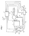
- Fig. 1 is a spark-ignition type gasoline engine
- 2 is an intake passage
- 3 is an intake throttle valve.
- Fuel injection valves 4 are formed to supply fuel directly to each cylinder of the engine 1.
- lean stratified combustion may be performed by setting the fuel injection timing of the fuel injection valves 4 to coincide with the compression stroke, or stoichiometric or rich premixing combustion can be performed by setting the fuel injection timing of the fuel injection valves 4 to coincide with the intake stroke.
- the fuel injection valves 4 may inject fuel into the intake passage 2 downstream of the throttle valve3.
- the opening timing of at least the exhaust valve may be varied by a variable valve mechanism.
- An exhaust gas passage 5 comprises first and second exhaust manifolds 5a, 5b corresponding to a first cylinder group and second cylinder group of the engine 1, and an exhaust gas tube 5c which combines the exhaust gases from these first and second manifolds 5a, 5b.
- a three-way catalyst 21 which functions as a first front catalyst and a three-way catalyst 22 which functions as a second front catalyst are respectively installed in the first and second exhaust manifolds 5a, 5b.
- An NOx absorption/reduction type three-way catalyst 23 is installed in the downstream exhaust gas tube 5c as a rear catalyst.
- the upstream three-way catalysts 21, 22 are installed in the exhaust manifolds of the engine so that the temperature increases immediately after startup, and the downstream three-way catalyst 23 is installed for example under the floor of the vehicle away from the engine 1 to maintain its heat resisting properties.
- the exhaust discharged from the first and second cylinder groups is led to the three-way catalysts 21 and 22 respectively. Therein, NOx is reduced and HC, CO are oxidized with maximum efficiency at the stoichiometric air-fuel ratio.
- NOx absorption/reduction three-way catalyst 23 performs reduction of NOx and oxidation of HC, CO with the greatest conversion efficiency at the stoichiometric air-fuel ratio, NOx in the exhaust gas is absorbed when the air-fuel ratio is lean. This NOx is desorbed when the oxygen concentration of the exhaust gas falls, e.g. at the stoichiometric air-fuel ratio or a rich air-fuel ratio, and the desorbed NOx is reduced by HC and CO in the exhaust gas.
- a control unit 11 To control the fuel injection amount and fuel injection timing of the above-mentioned fuel injection valves 4 according to running conditions, a control unit 11 is provided.
- EGR exhaust gas recirculation
- An EGR control valve installed in the EGR passage 41 is controlled by the control unit 11 to control a flow amount of a EGR gas based on the running condition.
- signals from a water temperature sensor which detects an engine cooling water temperature, a gear position sensor which detects the gear position of a transmission, an accelerater position sensor which detects an accelerater depression amount, and a vehicle speed sensor which detects vehicle speed are also input. Based on these signals, the fuel injection amount and fuel injection timing of the fuel injection valves 4 are controlled, and the ignition timing of a spark plug, not shown, and the valve opening timing of the exhaust valve, are variably controlled.
- control when sulfur oxides (SOx) in the exhaust gas have deposited on the NOx absorption/reduction three-way catalyst 23 and NOx absorption declines, control is performed for eliminating the deposited SOx.
- the air-fuel ratios of the cylinder groups are set so that the air-fuel ratio of the exhaust gas flowing into the three-way catalyst 21 in one of the exhaust passages is richer than the stoichiometric air-fuel ratio, the air-fuel ratio of the exhaust gas flowing into the other three-way catalyst 22 is lean, and the air-fuel ratio of the exhaust gas after the two exhaust gas streams are combined is the stoichiometric air-fuel ratio or an air-fuel ratio richer than stoichiometric.
- a lean gaseous mixture flows into the three-way catalyst 21
- a rich gaseous mixture flows into the three-way catalyst 22, and excess unburnt components and oxygen which do not contribute to the catalytic reaction and oxygen flow downstream and into the NOx absorption/reduction three-way catalyst 23.
- the reaction in the three-way catalyst 23 is promoted by the unburnt components and oxygen, and the catalyst temperature rises. This discharges SOx which has been absorbed and accumulated on the three-way catalyst 23, and reduces and purifies the SOx, so that the function of the catalyst 23 is restored.
- the upstream three-way catalysts 21, 22 have either a lean or rich air-fuel ratio, their catalytic reactions are suppressed, preventing their temperatures from rising excessively which would damage their durability.
- control unit 11 The details of the control performed by the control unit 11 will now be described in detail by the following flowcharts.
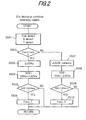
- Fig. 2 is a determining routine (1) for determining the discharge conditions for SOx deposited on the NOx absorption/ reduction catalyst which is the rear catalyst, and it is performed at an interval of 10ms.
- the amount of SOx which the rear catalyst has absorbed and accumulated is estimated, and it is determined whether the amount of SOx deposited on the catalyst has reached a predetermined value, i.e. whether or not the conditions for discharging SOx hold.
- step S501 the output of the catalyst temperature sensor is A/D converted to find a rear catalyst temperature Tcat. Also, an engine rotation speed N is calculated based on the occurrence interval of a predetermined signal of the crank angle sensor, and an engine load T (for example, a target generation torque of the engine depending on an accelerator depression amount) is calculated based on the output of the accelerator position sensor.
- an engine rotation speed N is calculated based on the occurrence interval of a predetermined signal of the crank angle sensor
- an engine load T for example, a target generation torque of the engine depending on an accelerator depression amount
- the rear catalyst temperature Tcat may be estimated based on engine rotation speed and engine load.
- Tcat of the rear catalyst it is determined whether or not the temperature Tcat of the rear catalyst is equal to or less than an SOx discharge temperature Tcat2 .
- Tcat2 SOx discharge temperature
- ⁇ SOXa which is the amount of SOx absorbed on the rear catalyst in a predetermined time (here 10ms) is computed.
- ⁇ SOXa (amount of SOx flowing into rear catalyst in predetermined time) * (SOx absorption coefficient of rear catalyst) .
- the amount of SOx flowing into the catalyst in predetermined unit time is computed as a parameter of, for example, the engine rotation speed N , engine load T and average air-fuel ratio
- the SOx absorption coefficient of the rear catalyst which is the amount of SOx absorbed in unit time
- the SOx absorption rate (SOx absorption amount in unit time) / (Sox introducing amount in unit time) .
- a target equivalent ratio TFBYA set by the target air-fuel ratio setting routine described hereafter, can be used.
- the SOx absorption rate of the rear catalyst is a value from 0 to 1, and it has the following characteristics relative to various parameters.
- the SOx absorption rate becomes larger the less the absorption amount of the rear catalyst, and is a maximum when the absorption amount is 0.
- the SOx absorption rate is a maximum when the catalyst temperature is a predetermined temperature. When the temperature is lower than the predetermined temperature, it decreases the lower the temperature, and is 0 below the catalyst activation temperature. When the temperature is higher than the predetermined temperature, it decreases the higher the temperature, and is 0 at or above the SOx discharge temperature.
- the SOx absorption coefficient decreases the smaller the leanness of the air-fuel ratio, and is 0 at an air-fuel ratio richer than stoichiometric.
- the SOx absorption amount ⁇ SOXa per a predetermined time is added to SOXz, the estimated amount of SOx computed on the immediately preceding occasion, to compute the most recent SOX.
- This permitted value SOXmax is set at such a level that a predetermined NOx absorption capacity, i.e., an absorption capacity NOXth , remains in the rear catalyst.
- the flag Fsox is set to 1 in S506.
- ⁇ SOXr (predetermined time) x (SOx discharge rate from rear catalyst)
- the SOx discharge rate of the rear catalyst is an SOx amount discharged in a predetermined unit time, and is computed as a parameter of, for example, the present SOx absorption amount (estimated value of SOx absorption amount computed on the immediately preceding occasion) SOXz, catalyst temperature Tcat and average air-fuel ratio.
- the target equivalent ratio TFBYA set by the target air-fuel ratio setting routine can be used as the average air-fuel ratio.
- the SOx discharge rate from the rear catalyst has the following characteristics relative to various parameters.
- the SOx discharge rate is smaller the less the SOx absorption amount.
- the SOx discharge rate is smaller the lower the catalyst temperature, and is 0 at or lower than the SOx discharge temperature.
- the SOx discharge rate is also smaller the less the richness of the air-fuel ratio, and is 0 at a lean air-fuel ratio.
- the most recent SOx is computed by subtracting ⁇ SOXr from the estimated SOx amount SOXz computed on the immediately preceding occasion.
- the predetermined value SOXmin is set to a small value near 0.
- the routine proceeds to S510, the flag Fsox is set to 0, and discharge of SOx is thereby completed.
- the estimated SOx amount SOX may be computed more simply. For example, S503 and S507 may be omitted and ⁇ SOXa , ⁇ SOXr in S504 and S508 may be set to fixed values. As absorption/discharge of SOx proceeds relatively slowly, it is sufficient if this routine is executed at an interval of 1 sec or 10sec. In this case, ⁇ SOXa, ⁇ SOXr may be computed as absorption discharge amount of SOx at an interval of 1 sec or 10sec.
- the SOx absorbed by the rear catalyst remains in the catalyst even after the engine stops, so the estimated SOX is stored even after the engine stops, and the stored SOX is used as an initial value for subsequent computation of SOX on the next occasion when the engine starts.
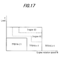
- Fig. 3 is a temperature rise control condition determining routine (1) of the rear catalyst, and it is performed at an interval of 10ms.
- the region A is a running region wherein the catalyst temperature Tcat can be raised to or above the SOx discharge temperature Tcat2 when temperature increase control is performed.
- the catalyst temperature Tcat can be increased to or above the SOx discharge temperature Tcat2 if temperature increase control is performed even in a region usually set as a lean operating region ( TFBYA ⁇ 1).
- TFBYA a region usually set as a lean operating region
- the rear catalyst discharges SOx more easily the higher the temperature, but if the temperature is increased excessively the durability of the catalyst is impaired, so temperature increase control is not performed when the temperature is higher than the permitted temperature Tcat3.
- the flag Fheat for determining temperature increase is set to 1 in S606, but when the temperature is higher the routine proceeds to S607 and the flag Fheat is set to 0.
- Fig. 4 is a routine for determining the conditions for enriching the total air-fuel ratio, and it is performed at an interval of 10ms.
- a flag Frich is set by determining whether the conditions for enriching the air-fuel ratio hold or do not hold, based on the determining flag Fsox of SOx discharge conditions and catalyst temperature.
- the output of the catalyst temperature sensor is A/D converted to compute the catalyst temperature Tcat.
- Fig. 5 shows a mode setting routine which performs lean and rich shift of the exhaust gas air-fuel ratio in the first and second cylinder groups, and it is performed at an interval of 10ms.
- the mode setting is changed over based on the variation of the determining flag Fsox of SOx discharge conditions.
- the first mode lean shift of the average air-fuel ratio of the exhaust gas led to the first front catalyst is performed, rich shift of the air-fuel ratio of the exhaust gas led to the second front catalyst is performed, and a flag Fmode is set to 1.
- the second mode the air-fuel ratios are set oppositely from the case of the first mode. In other words, in the second mode wherein the first front catalyst side is rich, and the second front catalyst side is lean, Fmode is set to 0.
- the value of the present Fmode is determined and Fmode is set to a value different from the present value.
- the mode setting is changed alternately, a situation where one front catalyst is always exposed to lean exhaust and the other front catalyst is always exposed to rich exhaust during temperature increase control of the rear catalyst is prevented, and a large difference in the rate of deterioration of the front catalysts is avoided.
- Fig. 6 is an air-fuel ratio control value setting routine (1), and it is performed at an interval of 10ms.
- the basic air-fuel ratio control parameters PL1 , PR1 , PL2 , PR2 , PHOSPL , PHOSPR , PHOSIL and PHOSIR are set based on the flags Fsox , Fheat , Frich and Fmode.
- PL1 , PR1 are basic control constants of proportional control for computing an air-fuel ratio feedback control correction coefficient ⁇ 1 for the first cylinder group based on the O 2 sensor output on the first front catalyst side ( PL1 : rich shift proportional gain, PR1 : lean shift proportional gain).
- PL1 > PR1 the control midpoint shifts to the rich side (the average air-fuel ratio of the exhaust gas led to the first front catalyst becomes richer), and when PL1 ⁇ PR1 , the control midpoint shifts to the lean side.
- PL2 and PR2 are basic control constants for computing an air-fuel ratio feedback control correction coefficient ⁇ 2 of the second cylinder group based on the output of the O 2 sensor on the second front catalyst side.
- PL2 > PR2 the control midpoint value shifts to the rich side (the average air-fuel ratio of the exhaust gas led to the second front catalyst becomes richer)
- PL2 ⁇ PR2 the control midpoint value shifts to the lean side.
- PHOSPL , PHOSPR , PHOSIL , and PHOSIR are basic control constants of proportional control and integral control for computing a correction value PHOS of dual O 2 sensor feedback control by the two front O 2 sensors based on the output of the rear O 2 sensor.
- PHOSPL rich shift proportional gain
- PHOSPR lean shift proportional gain
- PHOSIL rich shift integral gain
- PHOSIR lean shift integral gain.
- PHOSPL > PHOSPR or PHOSIL > PHOSIR a correction value PHOS is computed which shifts the average air-fuel ratio of the exhaust gases led to the first and second front catalysts, to rich.
- PHOSPL ⁇ PHOSPR or PHOSIL ⁇ PHOSIR a correction value PHOS is computed which shifts the average air-fuel ratio of the exhaust gases led to the first and second front catalysts, to lean.
- DHOS , DL1 , DR1 , DL2 and DR2 are control values of delay time control when the correction coefficients ⁇ 1 , ⁇ 2 are computed, but in this embodiment, all of these are set to 0 and delay time control is not performed.
- the set values PL1 , PR1 , PL2 and PR2 are used in the ⁇ computing routine, and the set values PHOSPL , PHOSPR , PHOSIL and PHOSIR are used in the PHOS computing routine.
- First DHOS , DL1 , DR1 , DL2 and DR2 are all set to 0 in S301.
- Fsox 1
- Fheat 1
- Frich 1
- Fmode 1
- the values PHOSPL , PHOSPR , PHOSIL and PHOSIR are first set to the values PHOSPLR , PHOSPRR , PHOSILR an d PHOSIRR , respectively.
- PHOSPLR , PHOSPRR , PHOSILR and PHOSIRR are values for computing the correction value PHOS which shifts the average air-fuel ratio of the exhaust gases to led to the rear catalyst, to richer than the stoichiometric air-fuel ratio.
- PHOSPLR , PHOSPRR , PHOSILR and PHOSIRR are generally in the relations PHOSPLR > PHOSPRR and PHOSILR > PHOSIRR .
- PHOSPLR , PHOSPRR , PHOSILR and PHOSIRR are stored in a memory (ROM) as single fixed values or as plural fixed values depending on the engine rotation speed and the load. Further, all or some of PHOSPLR , PHOSPRR and PHOSILR may be variably set according to the SOx discharge amount, and in this case are stored in an updatable memory (RAM).
- PLL and PRL are values which shift the average air-fuel ratio of the exhaust gas led to the first front catalyst to leaner than the stoichiometric air-fuel ratio.
- PLL , PRL are in the relation PLL ⁇ PRL .
- PLL and PRL are set so that the lean shift due to them is larger than the rich shift due to PHOSPLR , PHOSPRR , PHOSILR and PHOSIRR .
- PLL, PRL are stored in a memory (ROM) as single fixed values or as plural fixed values depending on the engine rotation speed and the load.
- PLR and PRR are values which shift the average air-fuel ratio of the exhaust gas led to the second front catalyst to richer than the stoichiometric air-fuel ratio.
- PLR , PRR are in the relation PLR ⁇ PRR .
- PLR and PRR are stored in a memory (ROM) as single fixed values or plural fixed values depending on the engine rotation speed and the load.
- PHOSPL , PHOSPR , PHOSIL and PHOSIR are set to the values PHOSPLR, PHOSPRR, PHOSILR and PHOSIRR, respectively.
- PL1 and PR1 are set to the values PLR and PRR respectively, and PL2 and PR2 are set to the values PLL and PRL respectively.
- the air-fuel ratio of the first front catalyst is thereby shifted to rich, and the air-fuel ratio of the second front catalyst is shifted to lean.
- PHOSPLS , PHOSPRS , PHOSILS and PHOSIRS are values for computing PHOS at which the average air-fuel ratio of the exhaust gas led to the rear catalyst is the stoichiometric air-fuel ratio.
- PHOSPLS and PHOSPRS are almost equal, and the values of PHOSILS and PHOSIRS are almost equal.
- PHOSPLS , PHOSPRS , PHOSILS and PHOSIRS are stored in a memory (ROM) as single fixed values or plural fixed values depending on the engine rotation speed and the load.
- PL1 and PR1 are set to the values PLL and PRL respectively, and PL2 and PR2 are set to the values PLR and PRR to respectively.
- the air-fuel ratios of the exhaust gases led to the first and second front catalysts are lean or rich, but the air-fuel ratio of the exhaust gas led to the rear catalyst is controlled to the stoichiometric air-fuel ratio.
- PL1 , PR1 are set to the values PLR , PRR , and PL2 , PR2 are set to the values PLL , PRL .
- the routine proceeds to S311.
- the flag Frich 1
- PHOSPL , PHOSPR , PHOSIL and PHOSIR are first set to the values PHOSPLR , PHOSPRR , PHOSILR and PHOSIRR in S312.
- PL1 , PR1 are set to the values PLS , PRS respectively.
- PLS , PRS are substantially equal.
- PLS , PRS are stored in a memory (ROM) as plural fixed values depending on the engine rotation speed and the load.
- PL2 , PR2 are also set to PLS , PRS , respectively.
- PHOSPL , PHOSPR , PHOSIL and PHOSIR are set to the values PHOSPLS , PHOSPRS , PHOSILS and PHOSIRS , respectively.
- PL1 , PR1 are set to the values PLS , PRS respectively
- PL2 , PR2 are set to the values PLS , PRS respectively.
- routine shown in Fig. 7 is a routine ( 1 ) for setting the rich shift proportional gain and lean shift proportional gain PHOSPLR and PHOSPRR , and it is performed at an interval of 10ms.
- the functions f1 and f2 are determined so that the rich shift amount has the following characteristics relative to various parameters.
- Fig. 8 is a routine (1) for computing the correction value PHOS . It is performed every time proportional control of air-fuel ratio feedback control is performed, and computes the correction value PHOS of dual O 2 sensor feedback control.
- This PHOS is reflected in proportional control of air-fuel ratio feedback control and varies the balance of rich shift proportional control and lean shift proportional control.
- an oxygen concentration signal OSR is compared with a slice level SLR in S283.
- the correction value PHOS of dual O 2 sensor feedback control is computed by proportional control using basic control constants (rich shift proportional gain PHOSPL and lean shift proportional gain PHOSPR ), and integral control using basic control constants (rich shift integral gain PHOSIL and lean shift integral gain PHOSIL ). Specifically, if OSR ⁇ SLR , a flag F21 is set to 0 in S284, otherwise the flag F21 is set to 1 in S285.
- PHOS PHOSz - PHOSPL in S289.
- Fig. 9 is a routine (1) for computing the air-fuel ratio feedback correction coefficient ⁇ 1 of the first cylinder group, and it is performed at an interval of 10ms.
- the correction coefficient ⁇ 1 of the air-fuel ratio feedback control of the first cylinder group is computed, and the computed correction coefficient ⁇ 1 is used in computing fuel injection amount and fuel injection timing in the routine for computing Ti and TITM .
- the air- fuel ratio feedback correction coefficient ⁇ 1 is computed as follows by proportional control using basic control constants (rich shift proportional gain PL1 and lean shift proportional gain PR1 ) and the correction value PHOS , integral control using basic control constants (rich shift integral gain IL1 and lean shift integral gain IR1 , and delay time control using basic control constants (rich shift delay time DL1 , lean shift delay time DR1 ) and the correction value DHOS, based on the result of comparing the oxygen concentration signal 0SF1 and a slice level SLF1 in S223.
- an air-fuel ratio inversion flag F11 is set to 0 in S224, otherwise the flag F11 is set to 1 in S225.
- the routine proceeds to S228, the timer TIMER1 is incremented, and TIMER1 is set to TIMER1z + ⁇ T .
- the subscript z denotes the value on the immediately preceding occasion (value computed 10ms earlier).
- delay time control is not performed as described above, so the results of S230 and S235 are never NO , proportional control is performed immediately alter inversion of the flag F11 , and integral control is performed when the flag F11 is not inverted.
- Fig. 10 is a routine (2) for computing the correction coefficient ⁇ 2 of the second cylinder group, and this is performed at an interval of 1Oms.
- the air-fuel ratio feedback correction coefficient ⁇ 2 for the second cylinder group is computed in S254-S269 by proportional control using basic control constants (rich shift proportional gain PL2 and lean shift proportional gain PR2 ) and the correction value PHOS , integral control using basic control constants (rich shift integral gain IL2 and lean shift integral gain IR2 ), and delay time control using basic control constants (rich shift delay time DL2 , lean shift delay time DR2 ) and the correction value DHOS , based on the result of comparing the oxygen concentration signal 0SF2 and a slice level SLF2 in S223, as was described for the above Fig. 9.
- the control routine is the same as that for computing the correction coefficient ⁇ 1 of the first cylinder group, so a detailed description here is omitted.
- Fig. 11 is a routine (1) which sets a target air-fuel ratio, and this is performed at an interval of 10ms.
- the target air-fuel ratio (target equivalent ratio) is set depending on the running conditions. This set target equivalent ratio is used for computing the fuel injection amount in a routine for computing the fuel injection amount, injection timing Ti and TITM , and also in other routines as a value representing the air-fuel ratio.
- the engine rotation speed N is calculated based on the occurrence interval of a predetermined signal from the crank angle sensor, and the engine load T is calculated based on the output of the accelerator position sensor (for example, a target generation torque of the engine according to the accelerator depression amount).
- the target equivalent ratio TFBYA is looked up based on the engine rotation speed N and engine load T from a target equivalent ratio setting map.
- Frich is a flag for performing SOx removal control of the rear catalyst. It is 1 when the conditions hold for shifting the air-fuel ratio to rich, and 0 when these conditions do not hold.
- TFBYA which was looked up from a map is less than 1, and when it is less than 1, TFBYA is set to 1 in S105.
- TFBYA is 1 even if the running conditions are in the lean air-fuel ratio running region. That is, once removal control has started, rich shift control is continued without migrating to lean running for as long as removal is possible (i.e., while the catalyst temperature is higher than the SOx discharge temperature).
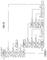
- Fig. 12 is a routine (1) for computing fuel injection amount, fuel injection timing Ti and TITM , and it is performed at an interval of 10ms.
- a fuel injection amount Ti1 and fuel injection timing TITM1 of the first cylinder group are computed.
- the computed Ti1 and TITM1 are stored in the memory of a control unit (ECM), and are read and used in the fuel injection routine which is performed in synchronism with the engine rotation.
- ECM control unit
- fuel injection is performed by applying a valve opening signal to a fuel injection valve which starts at a crank angle defined by TITM1 , and continuing application of the valve opening signal for a time obtained by adding an ineffectual pulse width Ts to Ti1 .
- the output of an air flow meter is A/D converted to calculate an intake air amount Qa , and the engine rotation speed N is calculated based on the occurrence interval of a predetermined signal of the crank angle sensor.
- Tp fuel amount corresponding to stoichiometric air-fuel ratio
- the fuel injection timing TITM1 is computed based on the computed Ti1 and engine rotation speed N.
- the fuel injection timing TITM1 is set in the compression stroke, and to obtain premixed combustion when running at the stoichiometric air-fuel ratio or a rich air-fuel ratio, the fuel injection timing TITM1 is set in the intake stroke.
- Fig. 13 is a routine (2) for computing the fuel injection amount, fuel injection timing Ti and TITM, and it is performed at an interval of 10ms.
- a fuel injection amount Ti2 and fuel injection timing TITM2 of the second cylinder group are computed.
- control is the same as that of the first cylinder group shown in Fig. 12 described above, and a detailed description here is omitted.
- Fig. 14 is a routine (1) for setting an ignition timing ADV , and it is performed at an interval of 10ms.
- the ignition timing ADV is set based on the flag Fheat , and based on the set ADV , an ignition signal is output to the spark plug by an ignition control routine, not shown.
- S701 it is determined from the flag Fheat whether or not the conditions for raising the temperature of the rear catalyst hold.
- the routine proceeds to S702, and the ignition timing ADV is computed by subtracting a predetermined retardation angle correction value RTD from an ignition timing ADVC preset according to running conditions (engine rotation speed N and engine load T ).
- the ignition timing ADV is set to ADVC in S713.
- ADVC is set for example as a timing at which the engine output is maximized provided that knocking does not occur.
- Fig. 15 is a routine (1) for setting an opening timing EVO of the exhaust valve, and it is performed at an interval of 10ms.
- the opening timing EVO of the exhaust valve is set based on the flag Fheat , and a drive signal is output to a valve control mechanism by a dynamic valve control routine, not shown, so as to obtain the set EVO .
- Fig. 16 is a routine for setting a valve aperture of the EGR valve, and if is performed at an interval of 10 ms.
- the EGR valve aperture is determined from the flag Fheat , and a driving signal is output to the EGR valve at a routine not shown.
- the EGR valve aperture EGR is set to 0 to prevent a EGR gas from circulating to the intake passage by closing the EGR valve.
- the EGR aperture EGR is set to a predetermined value EGRC based on the running conditions (engine rotation speed, engine load ). In this case, an exhaust gas temperature rises due to increasing of a combustion temperature when the EGR gas circulation is stopped.
- Ordinary control is therefore performed with the air-fuel ratio at the stoichiometric air-fuel ratio, and the system waits for the catalyst temperature to rise under ordinary control. It should be noted that when the vehicle is run at the stoichiometric air-fuel ratio during ordinary control, the average air-fuel ratios of both the first and second cylinder groups are controlled to the stoichiometric air-fuel ratio.
- the average air-fuel ratio of the exhaust led to the second front catalyst (average air-fuel ratio of the second cylinder group) is shifted to rich from the stoichiometric air-fuel ratio. Therefore, the purifying efficiency of the second front catalyst falls, and excess unburnt fuel components flow through the second front catalyst.
- the value of PHOS is a value at which the average air-fuel ratio of the exhaust gas led to the rear catalyst is the stoichiometric air-fuel ratio, and the average air-fuel ratio of the exhaust led to the rear catalyst is effectively the stoichiometric air-fuel ratio.
- the amount of excess oxygen flowing through the first front catalyst and the amount of excess unburnt fuel components flowing through the second front catalyst are substantially the same (exactly the amounts necessary for reaction), and the catalytic reaction in the rear catalyst is therefore performed most efficiently.
- the temperature increase effect on burnt fuel in the rear catalyst can be maximized. Also, by performing retardation angle control of the ignition timing, advance angle control of the exhaust valve opening timing and closing control of EGR valve aperture, exhaust gas temperature is increased and the temperature rise of the rear catalyst is assisted.
- the value of PHOS is a value at which the average air-fuel ratio of the exhaust led to the rear catalyst is shifted to rich. The average air-fuel ratio of the exhaust led to the rear catalyst is therefore shifted to rich from the stoichiometric air-fuel ratio.
- the lean shift due to PL1 and PR1 and the rich shift due to PHOS are performed simultaneously, the lean shift is less than during the period t2-t3.
- the rich shift due to PL2 and PR2 and the rich shift due to PHOS are performed simultaneously, the rich shift is larger than during the period t2-t3.
- the catalyst temperature Tcat reaches an upper limiting value Tcat3 during SOx discharge/reduction control, so to suppress further temperature rise, the flag Fheat is set to 0 and the same control is performed as during the interval t4-t5.
- While Fmode 0 and temperature increase control is performed, the average air-fuel ratio of the first cylinder group is rich and the average air-fuel ratio of the second cylinder group is lean, the remaining features being essentially identical to those described above.
- the air-fuel ratios of the exhaust gas flowing into the first and second front three-way catalysts are alternately changed over between rich and lean, so catalyst deterioration is subject to the same conditions on both sides and the durability of the catalyst is enhanced.
- Fig. 20 is a routine (2) for setting an air-fuel ratio control value, and it is performed at an interval of 10ms.
- the basic control constants DL1 , DR1 , DL2 and DR2 , and the correction value PHOS are set based on the flags Fsox , Fheat , Frich and Fmode .
- the difference from the first embodiment is that whereas the value of the correction value PHOS is computed based on the rear 02 sensor output during ordinary running when the conditions for discharging SOx absorbed by the rear catalyst do not hold, the value of PHOS is set by open control when they do hold.
- rear F/B conditions of the PHOS computing routine are as follows:
- DL1 , DR1 are basic control constants of delay time control when the correction coefficient ⁇ 1 of air-fuel ratio feedback control of the first cylinder group is computed based on the first front O 2 sensor output.
- the rich shift delay tune DL1 sets the delay time from when the first front O 2 sensor output inverts from rich to lean, to when rich shift proportional control is performed, and the lean shift delay time DR1 sets the delay time from when the first front O 2 sensor output inverts from lean to rich, to when lean shift proportional control is performed.
- DL1 ⁇ DR1 the control midpoint value is shifted to rich.
- DL2 , DR2 are basic control constants of delay time control when the correction coefficient ⁇ 2 of air-fuel ratio feedback control of the second cylinder group is computed based on the second front O 2 sensor output.
- the rich shift delay time DL2 sets the delay time from when the second front O 2 sensor output inverts from rich to lean, to when rich shift proportional control is performed
- the lean shift delay time DR2 sets the delay time from when the second front O 2 sensor output inverts from lean to rich, to when lean shift proportional control is performed.
- DL2 ⁇ DR2 the control midpoint value is shifted to rich.
- DHOS is a correction value of delay time control, but according to this embodiment, this value is set to a fixed value and the delay time control correction is not performed. Also, by setting the values of the basic control constants PL1 , PL2 of proportional control to PLS , and setting the values of PR1 , PR2 to PRS , a rich/ lean shift for each cylinder group is not generated.
- the set DL1 , DR1 , DL2 , DR2 and PHOS are used by the routine for computing the correction coefficient ⁇ .
- the set PHOSPL , PHOSPR , PHOSIL and PHOSIR are used by the routine for computing the correction value PHOS.
- DHOS DHOSS (it may be 0)
- PL1 PLS
- PR1 PRS
- PHOSR is first set to PHOS .
- PHOSR is the value by which the average air-fuel ratio of the exhaust led to the rear catalyst is shifted to rich from the stoichiometric air-fuel ratio.
- PHOSR is stored in a memory (ROM) as a single fixed value or as plural fixed values depending on the engine rotation speed and the load.
- ROM memory
- PHOSR may be variably set according to the SOx discharge amount, and in this case is stored in an updatable memory (RAM).
- DL1 and DR1 are set to the values DLL , DRL .
- DLL , DRL are values which shift the average air-fuel ratio of the exhaust led to the first front catalyst to lean from the stoichiometric air-fuel ratio.
- DLL , DRL are in the relation DLL > DRL , and DRL may also be 0. Also, the values of DLL , DRL are set so that the lean shift due to DLL and DRL is larger than the rich shift due to PHOSR . As in the above-mentioned cases , DLL , DLR are stored in a memory (ROM) as single fixed values or as plural fixed values depending on the engine rotation speed and the load.
- DL2 and DR2 are set to the values DLR , DRR .
- DLL , DRL are values which shift the average air-fuel ratio of the exhaust led to the second front catalyst to rich from the stoichiometric air-fuel ratio.
- DLR , DRR are in the relation DLR ⁇ DRR, and DLL may also be 0.
- DLR , DRR are stored in a memory (ROM) as single fixed values or as plural fixed values depending on the engine rotation speed and the load.
- PHOS is first set to the value PHOSR in S327. Also, DL1 , DR1 are set to the values DLR , DRR , and DL2 , DR2 are set to the values DLL , DRL .
- the exhaust gas air-fuel ratio of the first front catalyst is rich, and the exhaust gas air-fuel ratio of the second front catalyst is lean.
- PHOSS is a value at which the average air-fuel ratio of the exhaust gas led to the rear catalyst is the stoichiometric air-fuel ratio.
- PHOSS is stored in a memory (ROM) as a single fixed value or as plural fixed values depending on the engine rotation speed and the load.
- PHOSS may be set to 0.
- the average value of PHOS computed during air-fuel ratio feedback control of using rear O 2 sensor may be used as PHOSS .
- DL1 , DR1 are set to the values DLL , DRL , and DL2 , DR2 are set to the values DLR , DRR .
- PHOS is set to the value PHOSS .
- DL1 , DR1 are set to the values DLR , DRR , and DL2 , DR2 are set to the values DLL , DRL .
- PHOS is set to the value PHOSR
- DL1 , DR1 are set to a value DS .
- DS is stored in a memory (ROM) as a single value or as plural values depending on the engine rotation speed and the load.
- the value of DS may be 0, or it may be set to a control period of the same order as DLL , DRL , DLR and DRR when air-fuel ratio feedback control is performed.
- DL2 , DR2 are set to the value DS .
- PHOS is set to the value PHOSS . Further, DL1 , DR1 are set to the value DS , and DL2 , DR2 are set to the value DS .
- the lean exhaust gas or rich exhaust gas overlap time is shortened as compared with the first embodiment where proportional control was performed, as shown by the lower part of Fig. 22, and it is therefore easy to ensure good temperature increase efficiency in the rear catalyst.
- a limit may be set on the delay time by a rich surface area equivalent amount or a lean surface area equivalent amount of the correction coefficient s ⁇ 1 , ⁇ 2.
- Fig. 21 is a PHOSR setting routine (1), and it is performed at an interval of 10ms. This is used when PHOSR of the air-fuel ratio control value setting routine (2) is set variably in conjunction with the SOx discharge amount.
- the function f3 is here determined so that the degree of rich shift has the following characteristics relative to various parameters.
- the air-fuel ratio is enriched according to the SOx amount absorbed and deposited by the rear catalyst, so there is no unnecessary enrichment of the air-fuel ratio and fuel consumption losses are reduced.
- the only difference from the first embodiment is the air-fuel ratio control value setting routine.
- Fig. 23 is an air-fuel ratio control value setting routine (3), and it is performed at an interval of 10ms.
- basic control constants DL1 , DR1 , DL2 , DR2 and the correction values PHOS , DHOS are set based on the flags Fsox , Fheaf , Frich and Fmode as described above.
- the value of the correction PHOS is computed based on the output of the rear O 2 sensor, and when the conditions do hold, the value of PHOS is set by open control.
- the rear catalyst F/B conditions of the PHOS computing routine are as follows.
- the correction value DHOS is reflected in delay time control of air-fuel ratio feedback control, and changes the balance between rich shift delay time and lean shift delay time.
- the control midpoint value of air-fuel ratio feedback control is shifted to rich, and when the value of DHOS is negative, the control midpoint value is shifted to lean.
- the set DL1 , DR1 , DL2 , DR2 , PHOS and DHOS are used in the routine for computing the correction coefficient ⁇ , and PHOSPL , PHOSPR , PHOSIL and PHOSIR which were similarly set are used in the routine for computing PHOS .
- Steps S341-S345 are the same as those of the air-fuel ratio control value setting routine (2) of the above-mentioned second embodiment, and are therefore omitted.
- PHOS is first set to the value PHOSS
- DHOS is set to the value DHOSR .
- DHOSR is a value which shifts the average air-fuel ratio of the exhaust gas led to the rear catalyst to rich from the stoichiometric air-fuel ratio.
- This DHOSR is stored by a memory (ROM) as a single fixed value or as plural fixed values depending on the engine rotation speed and the load.
- ROM memory
- DHOSR may be varied with the SOx discharge amount, in which case a value is stored in a memory (RAM).
- DL1 , DR1 are set to the values DLL , DRL, and DL2 , DR2 are set to the values DLR , DRR .
- the value PHOS is set to PHOSS
- the value DHOS is set to DHOSR .
- DL1 , DR1 are set to the values DLR , DRR , and DL2 , DR2 are set to the values DLL , DRL .
- PHOS is set to the value PHOSS
- DHOS is set to the value DHOSS .
- DHOSS is a value at which the average air-fuel ratio of the exhaust led to the rear catalyst becomes the stoichiometric air-fuel ratio.
- DL1 , DR1 are set to the values DLL , DRL , and DL2 , DR2 are set to the values DLR , DRR .
- PHOS is set to the value PHOSS
- DHOS is set to the value DHOSS
- DL1 , DR1 are set to the values DLR , DRR
- DL2 and DR2 are set to the values DLL , DRL .
- PHOS is set to the value PHOSR
- DHOS is set to the value DHOSS
- DL1 , DR1 are set to the value DS
- DL2 , DR2 are set to the value DS .
- DHOS is set to the value DHOSS even if PHOS is set to the value PHOSS .
- DL1 , DR1 are set to the value DS
- DL2 , DR2 are set to the value DS .
- Fig. 24 is a DHOSR setting routine (1), and it is performed at an interval of 10ms.
- the function f4 is set so that the degree of rich shift has the following characteristics relative to each parameter. That is, the degree of rich shift becomes less the smaller the SOx discharge amount from the rear catalyst, and is 0 when the absorption amount is 0. Also, the degree of rich shift is less the lower the catalyst temperature, and is 0 at or below the SOx discharge temperature.
- the fourth embodiment is different from the first-third embodiments only insofar as concerns the mode setting routine of the air-fuel ratio of the exhaust gas led to the first and second front catalysts, therefore the description will focus on this point.
- Fig. 25 is a mode setting routine (2), and it is performed at an interval of 10ms.
- a mode setting change-over is performed based on the elapsed tune from when the conditions for increasing the temperature of the rear catalyst hold.
- Fig. 26 is an SOx discharge condition determining routine (2), and it is performed at an interval of 10ms.
- the presence or absence of SOx deposition on the catalyst is determined based on the NOx concentration of the exhaust flowing from the rear catalyst, and a flag Fsox is set depending on whether conditions hold or do not hold for discharging SOx absorbed by the rear catalyst. In this case, when SOx discharge conditions hold, Fsox is set to 1, and when they do not hold, Fsox is set to 0.
- the output of the NOx sensor is A/D converted to determine an NOx concentration signal NOXS
- the output of the catalyst temperature sensor is A/D converted to determine the catalyst temperature Tcat.
- the engine rotation speed N is calculated based on the occurrence interval of a predetermined signal from the crank angle sensor
- the engine load T (for example, a target generated engine torque) depending on the accelerator depression amount) is calculated based on the output of the accelerator position sensor.
- an amount ⁇ NOX which is the amount of NOx absorbed by the rear catalyst in a predetermined time (here, 10ms), is computed.
- ⁇ NOX (NOx amount flowing into rear catalyst in a predetermined time) * (NOx absorption coefficient of rear catalyst) .
- the NOx amount flowing into the rear catalyst in a predetermined time is computed as a parameter of for example engine rotation speed N, engine load T and average air-fuel ratio.
- the NOx absorption rate of the rear catalyst (NOx amount absorbed in unit time/ Nox amount flowing into in unit time) is computed as a parameter of for example NOXz which is the present NOx absorption amount (estimated value of NOx absorption amount computed on immediately preceding occasion), catalyst temperature Tcat , and average air-fuel ratio.
- NOXz the present NOx absorption amount (estimated value of NOx absorption amount computed on immediately preceding occasion)
- catalyst temperature Tcat catalyst temperature
- average air-fuel ratio the target equivalent ratio TFBYA set by the target air-fuel ratio setting routine can be used.
- the NOx absorption rate of the rear catalyst is a value from 0 to 1, and it has the following characteristics relative to various parameters. Specifically, the NOx absorption rate is larger the smaller the NOx absorption amount, and is a maximum when the NOx absorption amount is 0.
- the NOx absorption rate is a maximum when the rear catalyst is at a predetermined temperature, becomes smaller the lower the temperature is below the predetermined temperature, and is 0 when the temperature is at or below the catalyst activation temperature. It also becomes smaller the higher the temperature is above a predetermined temperature.
- the NOx absorption rate becomes smaller the less the degree of leanness of the air-fuel ratio, and is 0 at an air-fuel ratio which is richer than the stoichiometric air-fuel ratio.
- ⁇ NOX is added to NOXz which is the estimated NOx amount computed on the immediately preceding occasion so as to compute NOX , which is the most recent estimated NOx amount.
- this estimated NOX is equal to or greater than a predetermined amount NOXth.
- the predetermined amount NOXth is set to, or a value slightly less than, an NOx absorption permitted amount of the rear catalyst.
- a flag Fnox which shows that the conditions hold for discharging NOx absorbed by the catalyst is set to 1 in S526.
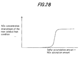
- the NOx absorption rate of the rear catalyst decreases the more the total amount of NOx and SOx absorbed by the rear catalyst increases, and when the NOx absorption rate decreases, the NOx amount discharged downstream of the rear catalyst increases.
- NOXSth By setting the NOx concentration corresponding to the NOx amount flowing downstream of the catalyst when the maximum permitted amount of SOx and the predetermined amount NOxth of NOx are absorbed by the catalyst, to a permitted value NOXSth , it may be determined whether or not the SOx amount deposited is equal to or greater than a permitted amount.
- the flag Fsox is set to 1 . Due to this, the conditions for discharging SOx from the rear catalyst hold, i.e. SOx removal control is permitted.
- the flag Fnox is then set to 0 in S531.
- S532 may for example be omitted, and ⁇ NOX of S534 may be set to a fixed value.
- PHOSPLR and PHOSPRR are made variable, as described in the first embodiment, the computation of the estimated SOx amount is not performed according to this embodiment, so PHOSPLR and PHOSPRR are set according to the elapsed time from when conditions hold for enriching the air-fuel ratio.
- the computation may be performed from when the conditions hold for enriching the air-fuel ratio.
- the SOX deposition amount on the rear catalyst may be precisely determined by measuring the NOx concentration, and completion of SOx removal can be estimated from the enriching time.
- Fig. 27 is a PHOSPLR , PHOSPRR setting routine (2), and it is performed at an interval of 10ms.
- PHOSPLR PHOSPRR of the air-fuel ratio control value setting routine are set variably in conjunction with the SOx discharge amount.
- f5 , f6 are determined so that the degree of rich shift has the following characteristics relative to various parameters.
- the degree of rich shift is smaller the lower the rear catalyst temperature, and is 0 at or below the SOx discharge temperature.
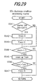
- Fig. 29 is an SOx discharge condition determining routine (3), and it is performed at an interval of 10ms.
- SOx removal control by enriching the air-fuel ratio is automatically performed only once after engine startup.
- the method of this routine is performed regardless of the SOx amount absorbed by the rear catalyst, so the SOx amount when air-fuel ratio enrichment control starts is not fixed.
Landscapes
- Engineering & Computer Science (AREA)
- Chemical & Material Sciences (AREA)
- Combustion & Propulsion (AREA)
- Mechanical Engineering (AREA)
- General Engineering & Computer Science (AREA)
- Biomedical Technology (AREA)
- Health & Medical Sciences (AREA)
- Environmental & Geological Engineering (AREA)
- Analytical Chemistry (AREA)
- General Chemical & Material Sciences (AREA)
- Oil, Petroleum & Natural Gas (AREA)
- Chemical Kinetics & Catalysis (AREA)
- Exhaust Gas After Treatment (AREA)
- Electrical Control Of Air Or Fuel Supplied To Internal-Combustion Engine (AREA)
Applications Claiming Priority (6)
| Application Number | Priority Date | Filing Date | Title |
|---|---|---|---|
| JP10476298 | 1998-04-15 | ||
| JP10476298 | 1998-04-15 | ||
| JP33247098 | 1998-11-24 | ||
| JP33247098 | 1998-11-24 | ||
| JP7949299 | 1999-03-24 | ||
| JP7949299 | 1999-03-24 |
Publications (3)
| Publication Number | Publication Date |
|---|---|
| EP0950803A2 true EP0950803A2 (fr) | 1999-10-20 |
| EP0950803A3 EP0950803A3 (fr) | 2001-06-06 |
| EP0950803B1 EP0950803B1 (fr) | 2003-09-03 |
Family
ID=27303030
Family Applications (1)
| Application Number | Title | Priority Date | Filing Date |
|---|---|---|---|
| EP99107288A Expired - Lifetime EP0950803B1 (fr) | 1998-04-15 | 1999-04-14 | Dispositif de purification de gaz d'échappement d'un moteur à combustion interne |
Country Status (3)
| Country | Link |
|---|---|
| US (1) | US6237330B1 (fr) |
| EP (1) | EP0950803B1 (fr) |
| DE (1) | DE69910879T2 (fr) |
Cited By (15)
| Publication number | Priority date | Publication date | Assignee | Title |
|---|---|---|---|---|
| EP1083306A1 (fr) * | 1999-09-07 | 2001-03-14 | MAGNETI MARELLI S.p.A. | Procédé de controle auto-adaptive pour un systeme d'échappement d'un moteur à combustion interne |
| EP1036927A3 (fr) * | 1999-03-17 | 2003-06-18 | Nissan Motor Co., Ltd. | Dispositif d'épuration des gaz d'échappement d'un moteur à combustion interne |
| FR2844299A1 (fr) * | 2002-09-05 | 2004-03-12 | Bosch Gmbh Robert | Procede de fonctionnement d'un moteur a combustion interne et moteur a combustion interne mettant en oeuvre ce procede |
| WO2004059150A1 (fr) * | 2002-12-30 | 2004-07-15 | Volkswagen Aktiengesellschaft | Procede de regulation de la temperature d'un catalyseur, et moteur multicylindre pourvu d'un systeme de purification de gaz d'echappement a division lambda |
| EP1205648B1 (fr) * | 2000-11-10 | 2006-03-15 | Volkswagen Aktiengesellschaft | Procédé et dispositif pour le chauffage d'un catalysateur |
| WO2006083393A1 (fr) * | 2005-02-02 | 2006-08-10 | Honeywell International Inc. | Systeme de post-traitement de gaz d'echappement pour un moteur a combustion interne |
| DE102004002292B4 (de) * | 2004-01-16 | 2010-08-12 | Audi Ag | Abgaskatalysator und Verfahren zum Betreiben einer Abgaskatalysatorvorrichtung |
| US9170573B2 (en) | 2009-09-24 | 2015-10-27 | Honeywell International Inc. | Method and system for updating tuning parameters of a controller |
| US9650934B2 (en) | 2011-11-04 | 2017-05-16 | Honeywell spol.s.r.o. | Engine and aftertreatment optimization system |
| US9677493B2 (en) | 2011-09-19 | 2017-06-13 | Honeywell Spol, S.R.O. | Coordinated engine and emissions control system |
| US10235479B2 (en) | 2015-05-06 | 2019-03-19 | Garrett Transportation I Inc. | Identification approach for internal combustion engine mean value models |
| US10415492B2 (en) | 2016-01-29 | 2019-09-17 | Garrett Transportation I Inc. | Engine system with inferential sensor |
| US10503128B2 (en) | 2015-01-28 | 2019-12-10 | Garrett Transportation I Inc. | Approach and system for handling constraints for measured disturbances with uncertain preview |
| US10621291B2 (en) | 2015-02-16 | 2020-04-14 | Garrett Transportation I Inc. | Approach for aftertreatment system modeling and model identification |
| US11156180B2 (en) | 2011-11-04 | 2021-10-26 | Garrett Transportation I, Inc. | Integrated optimization and control of an engine and aftertreatment system |
Families Citing this family (92)
| Publication number | Priority date | Publication date | Assignee | Title |
|---|---|---|---|---|
| DE19920520C2 (de) * | 1999-05-05 | 2001-04-26 | Daimler Chrysler Ag | Vorrichtung zur Rückführung des Abgases einer Brennkraftmaschine |
| JP4330048B2 (ja) * | 1999-06-11 | 2009-09-09 | ヤマハ発動機株式会社 | 船外機用多気筒4サイクルエンジン |
| US6360530B1 (en) | 2000-03-17 | 2002-03-26 | Ford Global Technologies, Inc. | Method and apparatus for measuring lean-burn engine emissions |
| US6860100B1 (en) * | 2000-03-17 | 2005-03-01 | Ford Global Technologies, Llc | Degradation detection method for an engine having a NOx sensor |
| US6487849B1 (en) * | 2000-03-17 | 2002-12-03 | Ford Global Technologies, Inc. | Method and apparatus for controlling lean-burn engine based upon predicted performance impact and trap efficiency |
| US6519933B2 (en) | 2000-03-21 | 2003-02-18 | Toyota Jidosha Kabushiki Kaisha | Internal combustion engine having variable valve control system and NOx catalyst |
| JP2001355485A (ja) * | 2000-06-16 | 2001-12-26 | Isuzu Motors Ltd | 窒素酸化物吸蔵還元型触媒を備えた排気ガス浄化装置 |
| JP4517463B2 (ja) * | 2000-06-22 | 2010-08-04 | マツダ株式会社 | エンジンの排気浄化装置 |
| DE10043687A1 (de) * | 2000-09-04 | 2002-03-14 | Bosch Gmbh Robert | Koordination verschiedener Anforderungen an die Abgastemperatur und entsprechende Heiz-oder Kühl-Maßnahmen |
| US6691507B1 (en) * | 2000-10-16 | 2004-02-17 | Ford Global Technologies, Llc | Closed-loop temperature control for an emission control device |
| US6360713B1 (en) * | 2000-12-05 | 2002-03-26 | Ford Global Technologies, Inc. | Mode transition control scheme for internal combustion engines using unequal fueling |
| US6389806B1 (en) * | 2000-12-07 | 2002-05-21 | Ford Global Technologies, Inc. | Variable displacement engine control for fast catalyst light-off |
| US6415601B1 (en) * | 2000-12-07 | 2002-07-09 | Ford Global Technologies, Inc. | Temperature management of catalyst system for a variable displacement engine |
| US6381953B1 (en) * | 2000-12-07 | 2002-05-07 | Ford Global Technologies, Inc. | Exhaust gas oxygen sensor temperature control for a variable displacement engine |
| US6553982B1 (en) * | 2001-02-16 | 2003-04-29 | Ford Global Technologies, Inc. | Method for controlling the phase difference of air/fuel ratio oscillations in an engine |
| US6553756B1 (en) | 2001-02-16 | 2003-04-29 | Ford Global Technologies, Inc. | Method for selecting a cylinder group when changing an engine operational parameter |
| JP4101475B2 (ja) * | 2001-05-18 | 2008-06-18 | 本田技研工業株式会社 | 内燃機関の排気浄化装置 |
| JP3659193B2 (ja) * | 2001-06-08 | 2005-06-15 | 日産自動車株式会社 | 内燃機関の排気浄化システム |
| US6615577B2 (en) | 2001-06-19 | 2003-09-09 | Ford Global Technologies, Llc | Method and system for controlling a regeneration cycle of an emission control device |
| US6467259B1 (en) | 2001-06-19 | 2002-10-22 | Ford Global Technologies, Inc. | Method and system for operating dual-exhaust engine |
| US6453666B1 (en) | 2001-06-19 | 2002-09-24 | Ford Global Technologies, Inc. | Method and system for reducing vehicle tailpipe emissions when operating lean |
| US6546718B2 (en) | 2001-06-19 | 2003-04-15 | Ford Global Technologies, Inc. | Method and system for reducing vehicle emissions using a sensor downstream of an emission control device |
| US6463733B1 (en) | 2001-06-19 | 2002-10-15 | Ford Global Technologies, Inc. | Method and system for optimizing open-loop fill and purge times for an emission control device |
| US6604504B2 (en) | 2001-06-19 | 2003-08-12 | Ford Global Technologies, Llc | Method and system for transitioning between lean and stoichiometric operation of a lean-burn engine |
| US6539706B2 (en) | 2001-06-19 | 2003-04-01 | Ford Global Technologies, Inc. | Method and system for preconditioning an emission control device for operation about stoichiometry |
| US6650991B2 (en) | 2001-06-19 | 2003-11-18 | Ford Global Technologies, Llc | Closed-loop method and system for purging a vehicle emission control |
| US6694244B2 (en) | 2001-06-19 | 2004-02-17 | Ford Global Technologies, Llc | Method for quantifying oxygen stored in a vehicle emission control device |
| US6691020B2 (en) | 2001-06-19 | 2004-02-10 | Ford Global Technologies, Llc | Method and system for optimizing purge of exhaust gas constituent stored in an emission control device |
| US6490860B1 (en) | 2001-06-19 | 2002-12-10 | Ford Global Technologies, Inc. | Open-loop method and system for controlling the storage and release cycles of an emission control device |
| US6487853B1 (en) | 2001-06-19 | 2002-12-03 | Ford Global Technologies. Inc. | Method and system for reducing lean-burn vehicle emissions using a downstream reductant sensor |
| US6502387B1 (en) | 2001-06-19 | 2003-01-07 | Ford Global Technologies, Inc. | Method and system for controlling storage and release of exhaust gas constituents in an emission control device |
| US6553754B2 (en) | 2001-06-19 | 2003-04-29 | Ford Global Technologies, Inc. | Method and system for controlling an emission control device based on depletion of device storage capacity |
| US6543219B1 (en) * | 2001-10-29 | 2003-04-08 | Ford Global Technologies, Inc. | Engine fueling control for catalyst desulfurization |
| JP3788350B2 (ja) * | 2002-01-07 | 2006-06-21 | 日産自動車株式会社 | 内燃機関の排気浄化装置 |
| US6725830B2 (en) * | 2002-06-04 | 2004-04-27 | Ford Global Technologies, Llc | Method for split ignition timing for idle speed control of an engine |
| US7168239B2 (en) * | 2002-06-04 | 2007-01-30 | Ford Global Technologies, Llc | Method and system for rapid heating of an emission control device |
| US20050193988A1 (en) * | 2004-03-05 | 2005-09-08 | David Bidner | System for controlling valve timing of an engine with cylinder deactivation |
| JP4135428B2 (ja) * | 2002-08-01 | 2008-08-20 | 日産自動車株式会社 | 内燃機関の排気浄化装置及び方法 |
| US6951098B2 (en) * | 2002-11-01 | 2005-10-04 | Ford Global Technologies, Llc | Method and system for controlling temperature of an internal combustion engine exhaust gas aftertreatment device |
| US6931839B2 (en) * | 2002-11-25 | 2005-08-23 | Delphi Technologies, Inc. | Apparatus and method for reduced cold start emissions |
| JP4304428B2 (ja) * | 2003-02-07 | 2009-07-29 | いすゞ自動車株式会社 | 内燃機関の排気ガス浄化システム |
| DE10310024B4 (de) * | 2003-02-28 | 2012-09-27 | Volkswagen Ag | Verfahren zur Aufheizung eines Katalysators |
| US7043901B2 (en) * | 2003-03-20 | 2006-05-16 | Ford Global Technologies, Llc | Device and method for internal combustion engine control |
| US7146799B2 (en) | 2003-03-27 | 2006-12-12 | Ford Global Technologies, Llc | Computer controlled engine air-fuel ratio adjustment |
| US6854264B2 (en) * | 2003-03-27 | 2005-02-15 | Ford Global Technologies, Llc | Computer controlled engine adjustment based on an exhaust flow |
| US7003944B2 (en) | 2003-03-27 | 2006-02-28 | Ford Global Technologies, Llc | Computing device to generate even heating in exhaust system |
| US6766641B1 (en) | 2003-03-27 | 2004-07-27 | Ford Global Technologies, Llc | Temperature control via computing device |
| US6883311B2 (en) * | 2003-07-02 | 2005-04-26 | Detroit Diesel Corporation | Compact dual leg NOx absorber catalyst device and system and method of using the same |
| US7263433B2 (en) | 2003-12-02 | 2007-08-28 | Ford Global Technologies, Llc | Computer device to calculate emission control device functionality |
| US7284368B2 (en) * | 2003-12-02 | 2007-10-23 | Ford Global Technologies Llc | Computer device to control operation during catalyst desulfurization to preserve catalytic function |
| US7073322B2 (en) * | 2004-03-05 | 2006-07-11 | Ford Global Technologies, Llc | System for emission device control with cylinder deactivation |
| US7044885B2 (en) * | 2004-03-05 | 2006-05-16 | Ford Global Technologies, Llc | Engine system and method for enabling cylinder deactivation |
| US7073494B2 (en) * | 2004-03-05 | 2006-07-11 | Ford Global Technologies, Llc | System and method for estimating fuel vapor with cylinder deactivation |
| US7028670B2 (en) * | 2004-03-05 | 2006-04-18 | Ford Global Technologies, Llc | Torque control for engine during cylinder activation or deactivation |
| US7086386B2 (en) * | 2004-03-05 | 2006-08-08 | Ford Global Technologies, Llc | Engine system and method accounting for engine misfire |
| US6978204B2 (en) * | 2004-03-05 | 2005-12-20 | Ford Global Technologies, Llc | Engine system and method with cylinder deactivation |
| US7367180B2 (en) * | 2004-03-05 | 2008-05-06 | Ford Global Technologies Llc | System and method for controlling valve timing of an engine with cylinder deactivation |
| US7025039B2 (en) * | 2004-03-05 | 2006-04-11 | Ford Global Technologies, Llc | System and method for controlling valve timing of an engine with cylinder deactivation |
| US7159387B2 (en) | 2004-03-05 | 2007-01-09 | Ford Global Technologies, Llc | Emission control device |
| FR2873404B1 (fr) * | 2004-07-20 | 2006-11-17 | Peugeot Citroen Automobiles Sa | DISPOSITIF DE DETERMINATION DE LA MASSE DE NOx STOCKEE DANS UN PIEGE A NOx ET SYSTEME DE SUPERVISION DE LA REGENERATION D'UN PIEGE A NOx COMPRENANT UN TEL DISPOSITIF |
| US7197867B2 (en) * | 2004-10-04 | 2007-04-03 | Southwest Research Institute | Method for the simultaneous desulfation of a lean NOx trap and regeneration of a Diesel particulate filter |
| US7743606B2 (en) * | 2004-11-18 | 2010-06-29 | Honeywell International Inc. | Exhaust catalyst system |
| US7182075B2 (en) * | 2004-12-07 | 2007-02-27 | Honeywell International Inc. | EGR system |
| US7165399B2 (en) * | 2004-12-29 | 2007-01-23 | Honeywell International Inc. | Method and system for using a measure of fueling rate in the air side control of an engine |
| US7328577B2 (en) | 2004-12-29 | 2008-02-12 | Honeywell International Inc. | Multivariable control for an engine |
| US7467614B2 (en) | 2004-12-29 | 2008-12-23 | Honeywell International Inc. | Pedal position and/or pedal change rate for use in control of an engine |
| US7275374B2 (en) * | 2004-12-29 | 2007-10-02 | Honeywell International Inc. | Coordinated multivariable control of fuel and air in engines |
| US7591135B2 (en) * | 2004-12-29 | 2009-09-22 | Honeywell International Inc. | Method and system for using a measure of fueling rate in the air side control of an engine |
| AU2006217106B2 (en) * | 2005-02-18 | 2010-07-29 | Graphic Packaging International, Llc | Carton with gusseted handle |
| US7752840B2 (en) * | 2005-03-24 | 2010-07-13 | Honeywell International Inc. | Engine exhaust heat exchanger |
| US7469177B2 (en) * | 2005-06-17 | 2008-12-23 | Honeywell International Inc. | Distributed control architecture for powertrains |
| US7389773B2 (en) | 2005-08-18 | 2008-06-24 | Honeywell International Inc. | Emissions sensors for fuel control in engines |
| US7155334B1 (en) | 2005-09-29 | 2006-12-26 | Honeywell International Inc. | Use of sensors in a state observer for a diesel engine |
| US7765792B2 (en) * | 2005-10-21 | 2010-08-03 | Honeywell International Inc. | System for particulate matter sensor signal processing |
| US7357125B2 (en) * | 2005-10-26 | 2008-04-15 | Honeywell International Inc. | Exhaust gas recirculation system |
| US20070144149A1 (en) * | 2005-12-28 | 2007-06-28 | Honeywell International Inc. | Controlled regeneration system |
| US7415389B2 (en) * | 2005-12-29 | 2008-08-19 | Honeywell International Inc. | Calibration of engine control systems |
| EP1939420A1 (fr) * | 2006-12-30 | 2008-07-02 | Umicore AG & Co. KG | Méthode de désulfurisation des catalyseurs à accumulation d'oxyde d'azote d'un système d'échappement pour un moteur à mélange pauvre |
| JP2009257181A (ja) * | 2008-04-16 | 2009-11-05 | Kubota Corp | 作業車 |
| US8060290B2 (en) | 2008-07-17 | 2011-11-15 | Honeywell International Inc. | Configurable automotive controller |
| WO2010089901A1 (fr) * | 2009-02-06 | 2010-08-12 | トヨタ自動車株式会社 | Dispositif de nettoyage d'échappement pour moteur à combustion interne |
| US8504175B2 (en) | 2010-06-02 | 2013-08-06 | Honeywell International Inc. | Using model predictive control to optimize variable trajectories and system control |
| JP6445928B2 (ja) * | 2015-05-19 | 2018-12-26 | 本田技研工業株式会社 | 内燃機関の点火装置 |
| EP3125052B1 (fr) | 2015-07-31 | 2020-09-02 | Garrett Transportation I Inc. | Résolveur de programme quadratique pour mpc utilisant une commande variable |
| US10272779B2 (en) | 2015-08-05 | 2019-04-30 | Garrett Transportation I Inc. | System and approach for dynamic vehicle speed optimization |
| US10124750B2 (en) | 2016-04-26 | 2018-11-13 | Honeywell International Inc. | Vehicle security module system |
| US10036338B2 (en) | 2016-04-26 | 2018-07-31 | Honeywell International Inc. | Condition-based powertrain control system |
| EP3548729B1 (fr) | 2016-11-29 | 2023-02-22 | Garrett Transportation I Inc. | Capteur de flux inférentiel |
| US10138822B2 (en) | 2016-12-16 | 2018-11-27 | Ford Global Technologies, Llc | Systems and methods for a split exhaust engine system |
| JP6520910B2 (ja) * | 2016-12-26 | 2019-05-29 | トヨタ自動車株式会社 | 内燃機関の制御装置 |
| US11057213B2 (en) | 2017-10-13 | 2021-07-06 | Garrett Transportation I, Inc. | Authentication system for electronic control unit on a bus |
| DE102019218427A1 (de) * | 2019-11-28 | 2021-06-02 | Robert Bosch Gmbh | Verfahren zur Diagnose von mehreren Lambdasonden |
Family Cites Families (16)
| Publication number | Priority date | Publication date | Assignee | Title |
|---|---|---|---|---|
| JPS5672235A (en) * | 1979-11-15 | 1981-06-16 | Nissan Motor Co Ltd | Safety device for cylinder number controlled engine |
| JPS5874841A (ja) * | 1981-10-28 | 1983-05-06 | Nissan Motor Co Ltd | 気筒数制御エンジン |
| JPH0460106A (ja) * | 1990-06-29 | 1992-02-26 | Mazda Motor Corp | エンジンの制御装置 |
| JPH04330320A (ja) * | 1991-04-30 | 1992-11-18 | Suzuki Motor Corp | エアサクションシステム |
| JPH0559935A (ja) * | 1991-09-03 | 1993-03-09 | Mitsubishi Automob Eng Co Ltd | 内燃エンジンの触媒劣化防止装置 |
| JP3189381B2 (ja) * | 1992-04-30 | 2001-07-16 | スズキ株式会社 | 内燃機関の空燃比制御装置 |
| JP3488982B2 (ja) * | 1992-09-18 | 2004-01-19 | 日産自動車株式会社 | 内燃機関の空燃比制御装置 |
| JP2754443B2 (ja) * | 1992-12-24 | 1998-05-20 | 本田技研工業株式会社 | 内燃機関の二次空気供給装置 |
| JP2962089B2 (ja) * | 1993-03-15 | 1999-10-12 | 日産自動車株式会社 | 内燃機関の触媒劣化診断装置 |
| JP2605579B2 (ja) | 1993-05-31 | 1997-04-30 | トヨタ自動車株式会社 | 内燃機関の排気浄化装置 |
| JPH07279713A (ja) * | 1994-04-11 | 1995-10-27 | Nippon Soken Inc | 排気ガス浄化装置 |
| JPH08144816A (ja) * | 1994-11-21 | 1996-06-04 | Honda Motor Co Ltd | 内燃機関の空燃比制御装置 |
| KR0177531B1 (ko) | 1996-06-19 | 1999-04-01 | 변성현 | 온구기 |
| US5758493A (en) * | 1996-12-13 | 1998-06-02 | Ford Global Technologies, Inc. | Method and apparatus for desulfating a NOx trap |
| JP3645704B2 (ja) * | 1997-03-04 | 2005-05-11 | トヨタ自動車株式会社 | 内燃機関の排気浄化装置 |
| JP3264226B2 (ja) * | 1997-08-25 | 2002-03-11 | トヨタ自動車株式会社 | 内燃機関の排気浄化装置 |
-
1999
- 1999-04-13 US US09/289,980 patent/US6237330B1/en not_active Expired - Lifetime
- 1999-04-14 EP EP99107288A patent/EP0950803B1/fr not_active Expired - Lifetime
- 1999-04-14 DE DE69910879T patent/DE69910879T2/de not_active Expired - Lifetime
Cited By (20)
| Publication number | Priority date | Publication date | Assignee | Title |
|---|---|---|---|---|
| EP1036927A3 (fr) * | 1999-03-17 | 2003-06-18 | Nissan Motor Co., Ltd. | Dispositif d'épuration des gaz d'échappement d'un moteur à combustion interne |
| US6679050B1 (en) | 1999-03-17 | 2004-01-20 | Nissan Motor Co., Ltd. | Exhaust emission control device for internal combustion engine |
| US6327848B1 (en) | 1999-09-07 | 2001-12-11 | Magneti Marelli S.P.A | Self-adapting control method for an exhaust system for internal combustion engines with controlled ignition |
| EP1083306A1 (fr) * | 1999-09-07 | 2001-03-14 | MAGNETI MARELLI S.p.A. | Procédé de controle auto-adaptive pour un systeme d'échappement d'un moteur à combustion interne |
| EP1205648B1 (fr) * | 2000-11-10 | 2006-03-15 | Volkswagen Aktiengesellschaft | Procédé et dispositif pour le chauffage d'un catalysateur |
| FR2844299A1 (fr) * | 2002-09-05 | 2004-03-12 | Bosch Gmbh Robert | Procede de fonctionnement d'un moteur a combustion interne et moteur a combustion interne mettant en oeuvre ce procede |
| WO2004059150A1 (fr) * | 2002-12-30 | 2004-07-15 | Volkswagen Aktiengesellschaft | Procede de regulation de la temperature d'un catalyseur, et moteur multicylindre pourvu d'un systeme de purification de gaz d'echappement a division lambda |
| DE102004002292B4 (de) * | 2004-01-16 | 2010-08-12 | Audi Ag | Abgaskatalysator und Verfahren zum Betreiben einer Abgaskatalysatorvorrichtung |
| WO2006083393A1 (fr) * | 2005-02-02 | 2006-08-10 | Honeywell International Inc. | Systeme de post-traitement de gaz d'echappement pour un moteur a combustion interne |
| US9170573B2 (en) | 2009-09-24 | 2015-10-27 | Honeywell International Inc. | Method and system for updating tuning parameters of a controller |
| US10309281B2 (en) | 2011-09-19 | 2019-06-04 | Garrett Transportation I Inc. | Coordinated engine and emissions control system |
| US9677493B2 (en) | 2011-09-19 | 2017-06-13 | Honeywell Spol, S.R.O. | Coordinated engine and emissions control system |
| US9650934B2 (en) | 2011-11-04 | 2017-05-16 | Honeywell spol.s.r.o. | Engine and aftertreatment optimization system |
| US11156180B2 (en) | 2011-11-04 | 2021-10-26 | Garrett Transportation I, Inc. | Integrated optimization and control of an engine and aftertreatment system |
| US10503128B2 (en) | 2015-01-28 | 2019-12-10 | Garrett Transportation I Inc. | Approach and system for handling constraints for measured disturbances with uncertain preview |
| US10621291B2 (en) | 2015-02-16 | 2020-04-14 | Garrett Transportation I Inc. | Approach for aftertreatment system modeling and model identification |
| US11687688B2 (en) | 2015-02-16 | 2023-06-27 | Garrett Transportation I Inc. | Approach for aftertreatment system modeling and model identification |
| US10235479B2 (en) | 2015-05-06 | 2019-03-19 | Garrett Transportation I Inc. | Identification approach for internal combustion engine mean value models |
| US10415492B2 (en) | 2016-01-29 | 2019-09-17 | Garrett Transportation I Inc. | Engine system with inferential sensor |
| US11506138B2 (en) | 2016-01-29 | 2022-11-22 | Garrett Transportation I Inc. | Engine system with inferential sensor |
Also Published As
| Publication number | Publication date |
|---|---|
| EP0950803A3 (fr) | 2001-06-06 |
| EP0950803B1 (fr) | 2003-09-03 |
| DE69910879T2 (de) | 2004-05-19 |
| DE69910879D1 (de) | 2003-10-09 |
| US6237330B1 (en) | 2001-05-29 |
Similar Documents
| Publication | Publication Date | Title |
|---|---|---|
| EP0950803B1 (fr) | Dispositif de purification de gaz d'échappement d'un moteur à combustion interne | |
| JP2871615B2 (ja) | 内燃機関の排気浄化装置 | |
| US5657625A (en) | Apparatus and method for internal combustion engine control | |
| US6679050B1 (en) | Exhaust emission control device for internal combustion engine | |
| EP1167726B1 (fr) | Dispositif de contrôle du rapport air/carburant d'un moteur à combustion interne | |
| EP0950804B1 (fr) | Dispositif pour la purification de gaz d'échappement d'un moteur à combustion interne | |
| US5595060A (en) | Apparatus and method for internal-combustion engine control | |
| US7036304B2 (en) | Exhaust gas purifying apparatus and method for internal combustion engine | |
| US6125628A (en) | Engine startup air-fuel ratio controller | |
| JP3360645B2 (ja) | 内燃機関の排気浄化装置 | |
| JPH08319862A (ja) | 内燃機関の制御装置 | |
| JP2737482B2 (ja) | 内燃機関における触媒コンバータ装置の劣化診断装置 | |
| JPH04231634A (ja) | 内燃エンジンの空燃比制御方法 | |
| JPH09126004A (ja) | 内燃機関の制御装置 | |
| JP4276136B2 (ja) | エンジンの診断装置 | |
| JPH0763096A (ja) | 内燃機関の空燃比制御装置 | |
| JPH0617660B2 (ja) | 内燃機関の空燃比制御装置 | |
| JP3890775B2 (ja) | 内燃機関の空燃比制御装置 | |
| JP2864681B2 (ja) | 内燃エンジンの空燃比制御方法 | |
| JPH01151742A (ja) | エンジンの燃料供給制御装置 | |
| JPH0791296A (ja) | V型エンジンの排気浄化装置 | |
| JP2518260B2 (ja) | 内燃機関の空燃比制御装置 | |
| JP2002115536A (ja) | 内燃機関の排気浄化装置 | |
| JPH06101541A (ja) | 内燃機関の空燃比制御装置 | |
| JPH0718365B2 (ja) | 内燃機関の空燃比制御装置 |
Legal Events
| Date | Code | Title | Description |
|---|---|---|---|
| PUAI | Public reference made under article 153(3) epc to a published international application that has entered the european phase |
Free format text: ORIGINAL CODE: 0009012 |
|
| 17P | Request for examination filed |
Effective date: 19990414 |
|
| AK | Designated contracting states |
Kind code of ref document: A2 Designated state(s): DE FR GB |
|
| AX | Request for extension of the european patent |
Free format text: AL;LT;LV;MK;RO;SI |
|
| PUAL | Search report despatched |
Free format text: ORIGINAL CODE: 0009013 |
|
| AK | Designated contracting states |
Kind code of ref document: A3 Designated state(s): AT BE CH CY DE DK ES FI FR GB GR IE IT LI LU MC NL PT SE |
|
| AX | Request for extension of the european patent |
Free format text: AL;LT;LV;MK;RO;SI |
|
| RIC1 | Information provided on ipc code assigned before grant |
Free format text: 7F 02D 41/02 A, 7F 01N 3/08 B, 7B 01D 53/94 B |
|
| 17Q | First examination report despatched |
Effective date: 20010823 |
|
| AKX | Designation fees paid |
Free format text: DE FR GB |
|
| GRAH | Despatch of communication of intention to grant a patent |
Free format text: ORIGINAL CODE: EPIDOS IGRA |
|
| GRAH | Despatch of communication of intention to grant a patent |
Free format text: ORIGINAL CODE: EPIDOS IGRA |
|
| GRAH | Despatch of communication of intention to grant a patent |
Free format text: ORIGINAL CODE: EPIDOS IGRA |
|
| GRAS | Grant fee paid |
Free format text: ORIGINAL CODE: EPIDOSNIGR3 |
|
| GRAA | (expected) grant |
Free format text: ORIGINAL CODE: 0009210 |
|
| AK | Designated contracting states |
Kind code of ref document: B1 Designated state(s): DE FR GB |
|
| REG | Reference to a national code |
Ref country code: GB Ref legal event code: FG4D |
|
| REF | Corresponds to: |
Ref document number: 69910879 Country of ref document: DE Date of ref document: 20031009 Kind code of ref document: P |
|
| ET | Fr: translation filed | ||
| PLBE | No opposition filed within time limit |
Free format text: ORIGINAL CODE: 0009261 |
|
| STAA | Information on the status of an ep patent application or granted ep patent |
Free format text: STATUS: NO OPPOSITION FILED WITHIN TIME LIMIT |
|
| 26N | No opposition filed |
Effective date: 20040604 |
|
| REG | Reference to a national code |
Ref country code: FR Ref legal event code: PLFP Year of fee payment: 17 |
|
| PGFP | Annual fee paid to national office [announced via postgrant information from national office to epo] |
Ref country code: GB Payment date: 20150408 Year of fee payment: 17 Ref country code: DE Payment date: 20150408 Year of fee payment: 17 |
|
| PGFP | Annual fee paid to national office [announced via postgrant information from national office to epo] |
Ref country code: FR Payment date: 20150408 Year of fee payment: 17 |
|
| REG | Reference to a national code |
Ref country code: DE Ref legal event code: R119 Ref document number: 69910879 Country of ref document: DE |
|
| GBPC | Gb: european patent ceased through non-payment of renewal fee |
Effective date: 20160414 |
|
| REG | Reference to a national code |
Ref country code: FR Ref legal event code: ST Effective date: 20161230 |
|
| PG25 | Lapsed in a contracting state [announced via postgrant information from national office to epo] |
Ref country code: GB Free format text: LAPSE BECAUSE OF NON-PAYMENT OF DUE FEES Effective date: 20160414 Ref country code: FR Free format text: LAPSE BECAUSE OF NON-PAYMENT OF DUE FEES Effective date: 20160502 Ref country code: DE Free format text: LAPSE BECAUSE OF NON-PAYMENT OF DUE FEES Effective date: 20161101 |