EP1009578B1 - Vorrichtung zum schweissen oder 'reflow'-löten eines werkstückes mit automatisch anpassung des drucks - Google Patents
Vorrichtung zum schweissen oder 'reflow'-löten eines werkstückes mit automatisch anpassung des drucks Download PDFInfo
- Publication number
- EP1009578B1 EP1009578B1 EP98928996A EP98928996A EP1009578B1 EP 1009578 B1 EP1009578 B1 EP 1009578B1 EP 98928996 A EP98928996 A EP 98928996A EP 98928996 A EP98928996 A EP 98928996A EP 1009578 B1 EP1009578 B1 EP 1009578B1
- Authority
- EP
- European Patent Office
- Prior art keywords
- electrode
- cylinder
- workpiece
- switch
- valve
- Prior art date
- Legal status (The legal status is an assumption and is not a legal conclusion. Google has not performed a legal analysis and makes no representation as to the accuracy of the status listed.)
- Expired - Lifetime
Links
Images


Classifications
-
- B—PERFORMING OPERATIONS; TRANSPORTING
- B23—MACHINE TOOLS; METAL-WORKING NOT OTHERWISE PROVIDED FOR
- B23K—SOLDERING OR UNSOLDERING; WELDING; CLADDING OR PLATING BY SOLDERING OR WELDING; CUTTING BY APPLYING HEAT LOCALLY, e.g. FLAME CUTTING; WORKING BY LASER BEAM
- B23K11/00—Resistance welding; Severing by resistance heating
- B23K11/24—Electric supply or control circuits therefor
-
- B—PERFORMING OPERATIONS; TRANSPORTING
- B23—MACHINE TOOLS; METAL-WORKING NOT OTHERWISE PROVIDED FOR
- B23K—SOLDERING OR UNSOLDERING; WELDING; CLADDING OR PLATING BY SOLDERING OR WELDING; CUTTING BY APPLYING HEAT LOCALLY, e.g. FLAME CUTTING; WORKING BY LASER BEAM
- B23K3/00—Tools, devices or special appurtenances for soldering, e.g. brazing, or unsoldering, not specially adapted for particular methods
- B23K3/08—Auxiliary devices therefor
-
- B—PERFORMING OPERATIONS; TRANSPORTING
- B23—MACHINE TOOLS; METAL-WORKING NOT OTHERWISE PROVIDED FOR
- B23K—SOLDERING OR UNSOLDERING; WELDING; CLADDING OR PLATING BY SOLDERING OR WELDING; CUTTING BY APPLYING HEAT LOCALLY, e.g. FLAME CUTTING; WORKING BY LASER BEAM
- B23K11/00—Resistance welding; Severing by resistance heating
- B23K11/24—Electric supply or control circuits therefor
- B23K11/25—Monitoring devices
- B23K11/252—Monitoring devices using digital means
- B23K11/255—Monitoring devices using digital means the measured parameter being a force
-
- B—PERFORMING OPERATIONS; TRANSPORTING
- B23—MACHINE TOOLS; METAL-WORKING NOT OTHERWISE PROVIDED FOR
- B23K—SOLDERING OR UNSOLDERING; WELDING; CLADDING OR PLATING BY SOLDERING OR WELDING; CUTTING BY APPLYING HEAT LOCALLY, e.g. FLAME CUTTING; WORKING BY LASER BEAM
- B23K11/00—Resistance welding; Severing by resistance heating
- B23K11/30—Features relating to electrodes
- B23K11/31—Electrode holders and actuating devices therefor
-
- B—PERFORMING OPERATIONS; TRANSPORTING
- B23—MACHINE TOOLS; METAL-WORKING NOT OTHERWISE PROVIDED FOR
- B23K—SOLDERING OR UNSOLDERING; WELDING; CLADDING OR PLATING BY SOLDERING OR WELDING; CUTTING BY APPLYING HEAT LOCALLY, e.g. FLAME CUTTING; WORKING BY LASER BEAM
- B23K11/00—Resistance welding; Severing by resistance heating
- B23K11/30—Features relating to electrodes
- B23K11/31—Electrode holders and actuating devices therefor
- B23K11/314—Spot welding guns, e.g. mounted on robots
Definitions
- This invention relates to pneumatically actuated resistance weld heads and reflow solder heads. More particularly, the invention relates to an apparatus for and a method of weld and reflow solder having an automatic cutoff of pressurized gas in a pneumatic cylinder when a desired weld force between an electrode and workpiece is attained.
- weld and “welding” shall refer to both resistance welding and reflow soldering systems and operations.
- Air-actuated weld heads typically include an air cylinder which controls the upward and downward motion of one or more electrodes used to weld or reflow solder a workpiece. Such weld heads are adjustable and may be adapted for welding different types of workpieces.
- these parameters include the duration and magnitude of electrical weld energy, and the weld force, which is the force exerted on the workpiece by the electrode.
- a maximum air pressure in the air cylinder is set separately from the weld force, which is usually set by precompressing a spring in the weld head connected between the air cylinder and the electrode.
- a problem associated with this manner of setting up the weld head for a new welding application is that, if set incorrectly, the air cylinder may continue to exert pressure on the electrode after the desired weld force has been attained resulting in excessive weld force.
- a force firing switch is operatively connected to the spring for sensing when the desired weld force is reached; that is, when the force applied by the air cylinder overcomes the precompression spring force.
- the force firing switch activates in response to a desired weld force, it signals a microcontroller in a welding power supply to supply electrical current to the electrode(s) to initiate welding.
- the air cylinder is preset by manually setting pressure regulators on the air cylinder to a maximum pressure at which the force firing switch just activates.
- Such manual operation invites human error. This may occur in the form of an inaccurate initial setting, or by the operator forgetting to reset the air pressure in the cylinder for a new welding application. Such inaccurate settings can result in either an excessive or inadequate weld force, resulting in damaged welds or insufficient pressure to activate the force firing switch.
- pressure settings in the air cylinder valves may drift, requiring subsequent adjustments to maintain the desired weld force.
- Such valve drift may go unnoticed through several welding operations, increasing the potential for unsatisfactory welds.
- continual adjustment increases the potential for human error.
- JP 62287785A which is considered to represent the most relevant state of the art
- US-A-4,572,940 US-A-3,889,094 and US 4.804,913 disclose various known arrangements for controlling the welding pressure or force at a welding head.
- the weld head includes a hydraulic cylinder instead of a pneumatic cylinder.
- the hydraulic system of the alternate embodiment operates in a manner analogous to that of the above described pneumatic system as the same principles of fluid dynamic apply.
- One embodiment of a pressure regulator system comprises a switching valve.
- the switching valve includes four ports: an inflow port; an exhaust port; a first gas line port; and a second gas line port. Attached to each of the gas tine ports is a two-way valve.
- the pressure regulator system includes a valve sensor for determining an activated state of a weld force sensor incorporated in the weld head.
- the pressure regulator system also includes means for substantially simultaneously closing and sealing the two-way valves on the first gas line port and the second gas line port when the sensor determines an activated state of the weld force sensor.
- a weld force in a pneumatically actuated welding system is controlled by performing the following steps which include moving an electrode onto a workpiece with a pneumatic cylinder and forcing the electrode onto the workpiece. Once a desired weld force is sensed between the electrode and the workpiece, the air supplied to and exhausted from the pneumatic cylinder is blocked. In this manner, the desired pressure in the pneumatic cylinder corresponding to the desired weld force is maintained in the cylinder during the welding operation.
- the above described embodiments of the invention provide several advantages over known weld heads. These advantages include eliminating human error due to inaccurate presetting of the maximum gas pressure in the pneumatic cylinder and automatic drift of the valve settings on the pneumatic cylinder, thereby improving the repeatability of the welding operation.
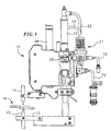
- an air-actuated resistance weld head 10 (or reflow solder head) according to one embodiment of the invention includes an air cylinder 12 which indirectly exerts force on an electrode 14, thereby controlling movement of the electrode and the force of the electrode on a workpiece 16.
- the workpiece 16 may be welded or reflow soldered on both sides between the electrode 14 and a stationary base electrode 14 on a base 13 of the weld head unit, or only on a top surface of the workpiece 16 with the electrode 14 alone.
- the weld head or reflow solder head 10 is connected to an air compressor (not shown) by gas line 70 and to a valve power supply 80 (see FIG. 6) by power line 72.
- weld and “welding” shall refer to both resistance welding and reflow soldering systems and operations.
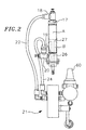
- the air cylinder 12 shown more clearly in FIG. 2, includes two ports, a down port 17 and an up port 19.
- a movable piston rod 26 (hereinafter referred to as the "actuating rod") includes a piston head 27 in sealing contact with the inner walls of the air cylinder 12 which forms two air chambers in the cylinder, an upper chamber A above the piston head 27 and a lower chamber B below the piston head 27.
- a pressure differential between the two air chambers A, B causes the actuating rod 26 to move in the air cylinder 12.
- the operator controls pressurized air in through one port of the air cylinder 12 and exhausts air through the other port.
- An up speed flow control valve 18 is attached to the down port 17 and a down speed flow control valve 20 is attached to the up port 19.
- the flow control valves 18, 20 permit a free flow of pressurized air when inputting air into the air cylinder 12 and restrict air flow to a pre-set degree when exhausting air from the air cylinder.
- the flow control valve exhausting air controls the rate of movement of the rod.
- the up speed flow control valve 18 controls the rate at which the actuating rod 26 moves up in the air cylinder and the down speed flow control valve 20 controls the rate at which the actuating rod 26 descends.
- Pressurized air from the air compressor is supplied to the air cylinder 12 through a switching valve 21, preferably a 24 volt four-way solenoid valve, which is connected to the down port 18 on the air cylinder via a down air line 22 and the up port 20 by a up air line 24.
- the switching valve 21 includes a pressure regulator 60 (fixed or adjustable) which is set to control the maximum air pressure in the cylinder in both the down air line 22 and the up air line 24 and hence, the maximum force exerted on the actuating rod 26.
- FIGs. 3A and 3B illustrate a valve system according to a preferred embodiment of the invention.
- the switching valve 21 has four ports: an air compressor port 44 for receiving pressurized air from the air compressor, preferably at a pressure between 60 and 100 psi; an exhaust port 46; a port 48 for the down air line 22; and a port 50 for the up air line 24.
- Pressurized air from the air compressor is set to a relatively high fixed pressure as it passes through regulator 60, preferably a fixed regulator set to about 60 psi, and is routed from the regulator 60 to the air compressor port 44 on the switching valve 21.
- the switching valve is controlled by the operator to switch the air input through the air compressor port 44 and exhausted from the exhaust port 46 between the down air line port 48 and the up air line port 50.
- the switching valve 21 is switched such that the pressurized air flowing into the air compressor port 44 is directed to the up air line port 50 and the pressurized air exhausted from the air cylinder 12 and through the down air line port 48 is directed to the exhaust port 46.
- This is the state of the switching valve 21 when the weld head is at rest and is also referred to as the "de-energized" state.
- pressurized air from the air compressor is routed to the down air line port 48 and exhaust from the up air line port 50 is routed to the exhaust port 46. This state is also referred to as the "energized" state.
- the embodiment of the valve system illustrated in FIGs. 3A and 3B also includes a two-way valve 52 and a two-way valve 54 incorporated into the up speed air line 22 and down speed air line 24, respectively.
- the two-way valves 52, 54 are positioned either between the flow control valves 18, 20 and the air cylinder 12 or between the flow control valves 18, 20 and the air line ports 48, 50 on the switching valve 21. The operation of these two-way valves according to the presently preferred embodiment is described in detail below.
- valve system including switching valve 21 and the two-way valves 52, 54, are electrically connected to and controlled by a valve power supply 80 which includes a microcontroller 82 for controlling the states of the various valves.
- the microcontroller 82 is operator controlled, preferably by a foot pedal (not shown), to switch the routing of pressurized air through the switching valve 21 in order to raise and lower the actuating rod 26 in the air cylinder 12.
- the air cylinder actuating rod 26 is connected to a spring tube 28 by a spring tube arm 30 such that the spring tube moves up and down with the air cylinder actuating rod 26.
- the spring tube houses one or more springs 32.
- the springs 32 may be precompressed to a desired precompression force setting by means of a threaded adjustment knob 34 housed in a threaded bore at the top of the spring tube 28.
- the electrode 14 is mounted to an electrode rod 36.
- the electrode rod 36 is connected to the spring tube 28 by an electrode rod arm 38.
- the electrode rod arm 38 is positioned in the spring tube 28 directly under the springs 32. When compressed, the springs 32 press the electrode rod arm 38 against a stop 39 positioned below the electrode rod arm 38.
- the electrode rod arm 38 moves with the spring tube arm 30 during most of the welding operation, but is not rigidly attached to it such that it has some free play. Accordingly, in the welding position, the electrode rod arm 38 can move relative to the spring tube 28 by pressing up on the springs 32 when the downwardly directed precompression force in the springs is overcome by a normal force exerted by the workpiece 16 on the electrode 14.
- the electrode 14 in an up stop position is lowered onto the workpiece 16 by controlling the air cylinder 12 to lower actuating rod 26, which in turn lowers the spring tube 28, and the electrode rod 36 with the electrode 14 onto the workpiece 16.
- the air cylinder 12 continues to exert downward force on the spring tube 28, thereby causing the electrode 14 to press onto the workpiece 16 with increasingly greater force.
- the workpiece 16 exerts an upward force component on the electrode 14 which approaches the downwardly directed precompression force exerted by the springs 32 in the spring tube 28 on the electrode arm 38.
- the spring tube 28 and the electrode rod arm 38 remain essentially stationary.
- the springs 32 begins to further compress. During this phase, the spring tube 28 continues descending, while the electrode rod arm 38 remains essentially stationary.
- a force firing switch 40 shown in FIG. 8, is mounted on the spring tube 28 and is sensitive to the downward movement of the spring tube 28 with respect to the electrode rod arm 38.
- the force firing switch 40 activates when the springs 32 compress and the spring tube moves a certain distance with respect to the electrode rod arm 38, typically about 1/16 inch.
- the springs 32 are set to a precompression force slightly below the desired weld force such that when the desired weld force is attained, the force firing switch 40 activates.
- the electrode 14 is electrically connected to and controlled by a welding power supply 90 which includes a microcontroller 92 for controlling the supply of electrical energy to the electrode 14 to initiate welding.
- the microcontroller 92 is connected to the force firing switch 40 via a cable 94 (FIG. 8) and is sensitive to the state of the force firing switch 40.
- the force firing switch 40 signals the welding power supply 90 to supply electrical current to the electrode 14, thereby energizing the electrode 14 to begin welding.
- the welding power supply microcontroller 92 de-energizes the electrode 14 when the welding is completed. This must be prior to the operator lifting the electrode off of the workpiece to avoid a blown weld. As the upward force exerted by the workpiece 16 on the electrode 14 is reduced, the springs 32 reexpand to their original (precompressed) length. Consequently, the force firing switch 40 deactivates.
- the operator precompresses the springs 32 with the spring adjusting knob 34 so that the springs 32 exert a downward force on the electrode rod arm 38 with a force slightly less than the desired weld force.
- the springs 32 begin to further compress and the spring tube 28 to move relative to the electrode rod arm 38.
- the force firing switch 40 activates when the desired weld force is attained between the electrode 14 and the workpiece 16.
- the valve power supply 80 includes a sensor 56 electrically connected to force firing switch, e.g., by cable 94 (FIG. 8).
- the sensor is sensitive to the state of the force firing switch 40.
- the two-way valves 52, 54 are electronically controlled to be in an open or a closed state by the microcontroller 82 in response to the state of the force firing switch 40. As illustrated in the diagram of FIG.
- the microcontroller 82 controls both two-way valves 52, 54 to close. Consequently, the pressure in the both chambers A, B of the air cylinder remains essentially constant, thereby maintaining a constant force exerted by the air cylinder actuating rod 26. With this constant force maintained in the actuating rod 26, the force of the electrode 14 on the workpiece 16 remains constant by way of the electrode rod, the electrode rod arm, and spring tube springs and the spring tube arm. During welding, the spring force in the springs 32 causes the electrode rod arm 38 and associated electrode 14 to move down to compensate for any deformation in the workpiece 16 due to the weld process.
- valve power supply 80 and the welding power supply 90, and their various components, are incorporated into a single unit.
- valve system such as that of the embodiment of FIGs. 3A and 3B, and the valve power supply 80 are provided as a kit to replace known switching valves and valve power supplies.
- the operator To operate a weld head according to one embodiment of the invention, the operator first presets the spring tube springs 32 to the desired weld force setting. From the up stop, or de-energized position (see FIG. 1), the operator commands microcontroller 82 to control the switching valve 21 to route compressed air from the air compressor port 44 through the down air line port 48 and exhausted air from the up air line port 50 through the exhaust port 46, as shown in FIG. 5, thereby forcing the actuating rod 26 down, which in turn lowers the electrode 14 onto the workpiece 16. After the electrode 14 contacts the workpiece 16, the air cylinder 12 continues exerting force on the actuating rod 26 and indirectly on the electrode 14 through the spring tube arm 30, spring tube spring 32, electrode rod arm 38, and electrode rod 36.
- the electrode rod arm 38 begins to exert upward pressure on the precompressed springs 32.
- the force exerted on the springs 32 exceeds the precompression (downward) force stored in the springs 32, the springs begin to further compress. This slight increased compression triggers the force firing switch 40 when the desired weld force is attained.
- sensor 56 signals the valve power supply microcontroller 82 to control two-way valves 52, 54 to close, as shown in FIG. 6, thereby maintaining an essentially constant pressure in both chambers A, B of the air cylinder 12, and consequently maintaining the desired weld force between the electrode 14 and the workpiece 16.
- the welding power supply microcontroller 92 de-energized the electrode 14.
- the valve power supply microcontroller 82 simultaneously opens the two-way valves 52, 54 and controls the switching valve 21 to route compressed air from the air compressor port 44 through the up air line port 50 and exhausted air from the down air line port 48 through the exhaust port 46 (see FIG. 4), thereby forcing the actuating rod 26 up, which in turn lifts the electrode 14 off of the workpiece 16.
- the force firing switch 40 deactivates once the desired weld force is lost.
- the present invention has been described with respect to particular embodiments, those skilled in the art will appreciate that the present invention may be modified without departing from the scope of the invention as defined in the appended claims.
- the pneumatic cylinder could be replaced by a hydraulic cylinder as the same principles of fluid mechanics utilized by the various embodiments of the invention apply.
- the microcontroller 82 of the valve power supply 80 of the above described embodiments may be replaced by any type of logic circuit, electronic or otherwise.
Landscapes
- Engineering & Computer Science (AREA)
- Mechanical Engineering (AREA)
- Robotics (AREA)
- Resistance Welding (AREA)
- Fluid-Pressure Circuits (AREA)
Claims (18)
- Vorrichtung (10) zum Schweißen oder Reflowlöten eines Werkstücks (16), umfassend:Eine Elektrode (14);einen Zylinder (12), der eine Betätigungsstange (26) umfasst, die wirkend mit der Elektrode (14) verbunden ist, um die Elektrode (14), als Reaktion auf eine Strömung unter Druckstehender Flüssigkeit im Zylinder (12) in einer ersten Richtung, auf das Werkstück (16) zu drücken und, als Reaktion auf eine Strömung einer unter Druck stehender Flüssigkeit im Zylinder (12) in einer entgegengesetzten Richtung, die Elektrode (14) vom Werkstück (16) zurückzuziehen;einen elektrischen Schalter (40) mit einer offenen Position und einer geschlossenen Position, wobei sich der Schalter (40) in die geschlossene Position bewegt, wenn die Elektrode (14) das Werkstück (16) mit einer vorbestimmten Kraft zusammendrückt;mindestens eine Feder (32), die an den elektrischen Schalter (40) gekoppelt ist, wobei die Feder angepasst ist, den elektrischen Schalter (40), als Reaktion auf die vorbestimmte Druckkraft der Elektrode (14) auf das Werkstück (16), zu schließen;Mittel zur Versorgung elektrischer Energie zur Elektrode (14), wenn sich der Schalter (40) in die geschlossene Position bewegt;Mittel zum Beibehalten eines erwünschten Drucks im Zylinder (12), der der vorbestimmten Kraft zwischen der Elektrode (14) und den Werkstück (16) entspricht, wenn sich der Schalter (40) in die geschlossene Position bewegt;Mittel zum Zurückziehen der Elektrode (14) vom Werkstück (16) nach dem eine vorbestimmte Menge elektrischer Energie der Elektrode (14) zugeführt worden ist, wobei die Reaktion der Elektrode (14) bewirkt, dass sich der Schalter (40) in die offene Position bewegt.
- Vorrichtung (10) nach Anspruch 1, wobei das Mittel zur Lieferung elektrischer Energie an die Elektrode eine Stromversorgung (90) umfasst, die wirkend mit der Elektrode (14) verbunden ist, wobei die Stromversorgung (90) einen Microcontroller (92) umfasst, der auf die Bewegung des Schalters (40) in die geschlossene Position anspricht.
- Vorrichtung (10) nach Anspruch 1, wobei der Zylinder (12) eine erste Flüssigkeitsleitung und eine zweite Flüssigkeitsleitung umfasst, wobei, wenn die Elektrode (14) auf das Werkstück (16) gedrückt wird, die erste Flüssigkeitsleitung unter Druck stehende Flüssigkeit zum Zylinder (12) mit einer erste Rate liefert und die zweite Flüssigkeitsleitung unter Druck stehende Flüssigkeit aus dem Zylinder (12) mit einer zweiten Rate ablässt, bis der erwünschte Druck im Zylinder (12) erreicht ist.
- Vorrichtung (10) nach Anspruch 3, wobei das Mittel zum Beibehalten des erwünschten Drucks im Zylinder (12) umfasst:Ein erstes Ventil (52), das wirkend mit der ersten Flüssigkeitsleitung verbunden ist und ein zweites Ventil (54), da wirkend mit der zweiten Flüssigkeitsleitung verbunden ist, wobei jedes der ersten und zweiten Ventile einen offenen Zustand und einen geschlossenen Zustand aufweist; undMittel zum Schließen sowohl des ersten Ventils (52) als auch des zweiten Ventils (54), während elektrische Energie zur Elektrode (14) geliefert wird.
- Vorrichtung (10) nach Anspruch 4, wobei das Mittel zum Schließen der Ventile (52, 54) eine Ventilstromversorgung umfasst, die wirkend mit dem elektrischen Schalter (40) und den ersten und zweiten Ventilen (52, 54) verbunden ist, wobei die Ventilstromversorgung umfasst:Ein Relais, das auf die Bewegung des elektrischen Schalters (40) in die geschlossene Position anspricht; undeinen Microcontroller, in elektrischer Schaltkreisbeziehung mit dem Relais, um zu bewirken, dass sich die ersten und zweiten Ventile schließen, wenn sich der Schalter schließt.
- Vorrichtung (10) nach Anspruch 2, die weiter ein Umschaltventil (21) aufweist, das umfasst:Einen Einströmanschluss (44);einen Ausströmanschluss (46);einen ersten Flüssigkeitsleitungsanschluss, der ein Zweiwegeventil umfasst, das wirkend mit der ersten Flüssigkeitsleitung verbunden ist; undeinen zweiten Flüssigkeitsleitungsanschluss, der ein Zweiwegeventil umfasst, das wirkend mit der zweiten Flüssigkeitsleitung verbunden ist, wobei jedes der Zweiwegeventile einen offenen Zustand und einen geschlossenen Zustand aufweist; undMittel zum Schalten jedes der Zweiwegeventile in den geschlossenen Zustand, wenn sich der Schalter in die geschlossene Position bewegt.
- Vorrichtung (10) nach Anspruch 6, wobei das Mittel zum Umschalten jedes der Zweiwegeventile (52, 54) eine Ventilstromversorgung umfasst, die wirkend mit dem elektrischen Schalter (40) und jedem der ersten und zweiten Ventile (52, 54) verbunden ist, wobei die Ventilstromversorgung umfasst:Ein Relais, das auf die Bewegung des elektrischen Schalters (40) in die geschlossene Position anspricht; undeinen Microcontroller, in elektrischer Schaltkreisbeziehung mit dem Relais, zum Steuern jedes der ersten und zweiten Ventile, damit sich diese schließen, wenn sich der Schalter schließt.
- Vorrichtung (10) nach Anspruch 1, wobei der Zylinder (12) ein pneumatischer Zylinder ist.
- Vorrichtung (10) nach Anspruch 8, wobei das Fluid Luft ist.
- Vorrichtung (10) nach Anspruch 1, wobei der Zylinder (12) ein hydraulischer Zylinder ist.
- Vorrichtung (10) nach Anspruch 10, wobei das Fluid (12) ein hydraulisches Fluid ist.
- Schweißverfahren oder Reflowlötverfahren unter Einsatz eines Systems (10), das einen Zylinder (12) und eine Zylinderstange (26) umfasst, die durch Einführen eines unter Druck stehenden Fluids in den Zylinder betätigt wird, wobei das Verfahren folgende Schritte umfasst:1) Bewegen einer Elektrode (14) auf ein Werkstück (16) mit der Betätigungsstange (26);2) Drücken der Elektrode (14) gegen das Werkstück (16) mit der Betätigungsstange (26);3) Abtasten, wann eine vorbestimmte Kraft zwischen der Elektrode (14) und dem Werkstück (16) erreicht ist, unter Einsatz einer Feder (32), die an einen elektrischen Schalter (40) gekoppelt ist und abdichten des unter Druck stehenden Fluids im Zylinder (12) als Reaktion darauf;4) Liefern elektrischer Energie zur Elektrode (14) auf dem Werkstück (16), um eine Schweißnaht oder Reflowlöten zu produzieren;5) Bebehalten eines erwünschten Drucks im Zylinder (12), der der vorbestimmten Schweißkraft entspricht, während das Werkstück (16) geschweißt oder reflowgelötet wird;6) Unterbrechen der Zufuhr elektrischer Energie zur Elektrode (14), wenn die Schweißung oder die Reflowlötung beendet ist; und7) Freigeben der Dichtung des im Zylinder (12) unter Druck stehenden Fluids und Zurückziehen der Elektrode (14), nach dem die Schweißung oder die Reflowlötung beendet ist.
- Verfahren nach Anspruch 12, wobei der Zylinder (12) einen pneumatischen Zylinder umfasst.
- Verfahren nach Anspruch 13, wobei das Fluid Luft ist.
- Verfahren nach Anspruch 12, wobei der Zylinder (12) einen hydraulischen Zylinder umfasst.
- Verfahren nach Anspruch 15, wobei das Fluid (12) ein hydraulisches Fluid ist.
- Vorrichtung (10) nach Anspruch 1, wobei die Feder (32) eine Schraubenfeder ist.
- Verfahren nach Anspruch 12, wobei die Feder (32) eine Schraubenfeder ist.
Applications Claiming Priority (3)
| Application Number | Priority Date | Filing Date | Title |
|---|---|---|---|
| US08/874,386 US5954976A (en) | 1997-06-13 | 1997-06-13 | Method and apparatus for automatically adjusting air pressure in a pneumatic weld head |
| US874386 | 1997-06-13 | ||
| PCT/US1998/012086 WO1998056533A1 (en) | 1997-06-13 | 1998-06-12 | Pneumatic weld head with automatically adjusted pressure |
Publications (3)
| Publication Number | Publication Date |
|---|---|
| EP1009578A1 EP1009578A1 (de) | 2000-06-21 |
| EP1009578A4 EP1009578A4 (de) | 2004-09-15 |
| EP1009578B1 true EP1009578B1 (de) | 2007-09-05 |
Family
ID=25363624
Family Applications (1)
| Application Number | Title | Priority Date | Filing Date |
|---|---|---|---|
| EP98928996A Expired - Lifetime EP1009578B1 (de) | 1997-06-13 | 1998-06-12 | Vorrichtung zum schweissen oder 'reflow'-löten eines werkstückes mit automatisch anpassung des drucks |
Country Status (9)
| Country | Link |
|---|---|
| US (1) | US5954976A (de) |
| EP (1) | EP1009578B1 (de) |
| JP (1) | JP2002504025A (de) |
| KR (1) | KR20010013706A (de) |
| AU (1) | AU745484B2 (de) |
| CA (1) | CA2293579C (de) |
| DE (1) | DE69838391T2 (de) |
| TW (1) | TW352350B (de) |
| WO (1) | WO1998056533A1 (de) |
Families Citing this family (5)
| Publication number | Priority date | Publication date | Assignee | Title |
|---|---|---|---|---|
| US6294750B1 (en) * | 1997-06-13 | 2001-09-25 | Unitek Miyachi Corporation | Method and apparatus for automatically adjusting air pressure in a pneumatic weld head |
| DE10017677C1 (de) * | 2000-04-08 | 2002-01-03 | Niepenberg Dalex Werke | Schweißeinrichtung |
| US20080290073A1 (en) * | 2007-02-19 | 2008-11-27 | Techmatrix, Llc | Single Weld Head |
| CN101590562B (zh) * | 2009-06-24 | 2011-04-20 | 镇江泛沃汽车零部件有限公司(中外合资) | 电阻焊接设备及焊接控制方法 |
| DE102010042085A1 (de) * | 2010-10-06 | 2012-04-12 | Siemens Aktiengesellschaft | Schweißkopf mit Kraftsensor |
Family Cites Families (14)
| Publication number | Priority date | Publication date | Assignee | Title |
|---|---|---|---|---|
| US2472368A (en) * | 1947-07-18 | 1949-06-07 | Cutler Hammer Inc | Plasticity responsive welder |
| GB1232626A (de) * | 1968-05-22 | 1971-05-19 | ||
| US3553420A (en) * | 1969-07-11 | 1971-01-05 | Gen Motors Corp | Method and apparatus for control of resistance welding |
| US3727822A (en) * | 1970-10-05 | 1973-04-17 | Gen Electric | Electromagnetic force system for integrated circuit fabrication |
| DE2257537A1 (de) * | 1972-11-23 | 1974-05-30 | Siemens Ag | Steuervorrichtung, insbesondere fuer ein widerstandsschweissgeraet |
| US4317980A (en) * | 1980-01-02 | 1982-03-02 | International Business Machines Corporation | Resistance welding sequence cycle control |
| JPS5890383A (ja) * | 1981-11-25 | 1983-05-30 | Matsushita Electric Ind Co Ltd | 抵抗溶接機の制御方法 |
| JPS59117902A (ja) * | 1982-12-23 | 1984-07-07 | S G:Kk | 流体圧シリンダの位置決め制御装置 |
| NL8304167A (nl) * | 1983-12-05 | 1985-07-01 | Weld Equip Bv | Laskop voor weerstandslassen. |
| JPH07115204B2 (ja) * | 1986-05-30 | 1995-12-13 | ミヤチテクノス株式会社 | 抵抗溶接機 |
| JPS6380982A (ja) * | 1986-09-22 | 1988-04-11 | Ohara Kinzoku Kogyo Kk | 溶接機用制御装置 |
| JPH0679787B2 (ja) * | 1988-01-26 | 1994-10-12 | 本田技研工業株式会社 | 自動溶接機における溶接ガンの電極チップ管理方法 |
| US5360958A (en) * | 1993-05-17 | 1994-11-01 | Delco Electronics Corporation | Welding apparatus having coaxial welding electrodes |
| US5545872A (en) * | 1994-03-14 | 1996-08-13 | Honda Giken Kogyo Kabushiki Kaisha | Pressure controller and pressure control method for resistance welder |
-
1997
- 1997-06-13 US US08/874,386 patent/US5954976A/en not_active Expired - Lifetime
-
1998
- 1998-06-12 EP EP98928996A patent/EP1009578B1/de not_active Expired - Lifetime
- 1998-06-12 DE DE69838391T patent/DE69838391T2/de not_active Expired - Lifetime
- 1998-06-12 TW TW087109417A patent/TW352350B/zh not_active IP Right Cessation
- 1998-06-12 WO PCT/US1998/012086 patent/WO1998056533A1/en not_active Ceased
- 1998-06-12 JP JP50318599A patent/JP2002504025A/ja active Pending
- 1998-06-12 KR KR1019997011721A patent/KR20010013706A/ko not_active Withdrawn
- 1998-06-12 AU AU80665/98A patent/AU745484B2/en not_active Ceased
- 1998-06-12 CA CA2293579A patent/CA2293579C/en not_active Expired - Fee Related
Also Published As
| Publication number | Publication date |
|---|---|
| US5954976A (en) | 1999-09-21 |
| TW352350B (en) | 1999-02-11 |
| WO1998056533A1 (en) | 1998-12-17 |
| HK1029075A1 (en) | 2001-03-23 |
| DE69838391T2 (de) | 2008-05-29 |
| CA2293579C (en) | 2010-06-01 |
| KR20010013706A (ko) | 2001-02-26 |
| AU8066598A (en) | 1998-12-30 |
| EP1009578A1 (de) | 2000-06-21 |
| DE69838391D1 (de) | 2007-10-18 |
| CA2293579A1 (en) | 1998-12-17 |
| JP2002504025A (ja) | 2002-02-05 |
| AU745484B2 (en) | 2002-03-21 |
| EP1009578A4 (de) | 2004-09-15 |
Similar Documents
| Publication | Publication Date | Title |
|---|---|---|
| US5060362A (en) | Slug riveting method and apparatus with C-frame deflection compensation | |
| US5652488A (en) | Welding electrode holder control | |
| EP1218138B1 (de) | Pneumatischer schweisskopf | |
| US20030079602A1 (en) | High speed driving method and apparatus of pressure cylinder | |
| US5954976A (en) | Method and apparatus for automatically adjusting air pressure in a pneumatic weld head | |
| US5349151A (en) | Low impact flow control device | |
| CN101352099A (zh) | 电阻焊接机的夹点安全传感器 | |
| HK1029075B (en) | Apparatus and method of welding or reflow soldering with automatically adjusted pressure | |
| US6198065B1 (en) | Resistance welding process and device | |
| JPH07214339A (ja) | 溶接ガン | |
| JP2003305573A (ja) | 電気抵抗溶接機の加圧装置 | |
| MXPA99011525A (en) | Pneumatic weld head with automatically adjusted pressure | |
| JPH07115204B2 (ja) | 抵抗溶接機 | |
| JPS5942223Y2 (ja) | 抵抗溶接機における電極ストロ−ク自動調整装置 | |
| JP2003205372A (ja) | 接合装置 | |
| JPH0227987Y2 (de) | ||
| JP2653244B2 (ja) | スタッド溶接装置 | |
| JPH07100659A (ja) | C型溶接ガンにおけるバランシングシリンダ制御装置 | |
| JPH04237580A (ja) | 抵抗溶接機 | |
| JP2001198680A (ja) | 抵抗溶接機の電極加圧制御方法と装置 | |
| JP2001259852A (ja) | スポット溶接ガンの加圧力可変装置 | |
| JP2668051B2 (ja) | 抵抗溶接方法及び抵抗溶接装置 | |
| JPH0760456A (ja) | C型溶接ガンにおけるバランシングシリンダ制御方法 | |
| JPH07185826A (ja) | クランプ装置および該装置を用いたスポット溶接機 | |
| JPH106032A (ja) | 固定電極の高さ調整装置 |
Legal Events
| Date | Code | Title | Description |
|---|---|---|---|
| PUAI | Public reference made under article 153(3) epc to a published international application that has entered the european phase |
Free format text: ORIGINAL CODE: 0009012 |
|
| 17P | Request for examination filed |
Effective date: 20000111 |
|
| AK | Designated contracting states |
Kind code of ref document: A1 Designated state(s): CH DE FR GB LI |
|
| A4 | Supplementary search report drawn up and despatched |
Effective date: 20040803 |
|
| RIC1 | Information provided on ipc code assigned before grant |
Ipc: 7B 23K 11/11 B Ipc: 7B 23K 11/31 B Ipc: 7B 23K 11/25 B Ipc: 7B 23K 3/00 B Ipc: 7B 23K 11/24 A |
|
| 17Q | First examination report despatched |
Effective date: 20050103 |
|
| RAP1 | Party data changed (applicant data changed or rights of an application transferred) |
Owner name: MIYACHI UNITEK CORPORATION |
|
| GRAP | Despatch of communication of intention to grant a patent |
Free format text: ORIGINAL CODE: EPIDOSNIGR1 |
|
| RTI1 | Title (correction) |
Free format text: APPARATUS ANDFOR AND METHOF OF WELDING OR REFLOW SOLDERING WITH AUTOMATICALLY ADJUSTED PRESSURE |
|
| GRAS | Grant fee paid |
Free format text: ORIGINAL CODE: EPIDOSNIGR3 |
|
| GRAA | (expected) grant |
Free format text: ORIGINAL CODE: 0009210 |
|
| AK | Designated contracting states |
Kind code of ref document: B1 Designated state(s): CH DE FR GB LI |
|
| REG | Reference to a national code |
Ref country code: GB Ref legal event code: FG4D |
|
| REG | Reference to a national code |
Ref country code: CH Ref legal event code: EP |
|
| REF | Corresponds to: |
Ref document number: 69838391 Country of ref document: DE Date of ref document: 20071018 Kind code of ref document: P |
|
| REG | Reference to a national code |
Ref country code: HK Ref legal event code: GR Ref document number: 1029075 Country of ref document: HK |
|
| ET | Fr: translation filed | ||
| PLBE | No opposition filed within time limit |
Free format text: ORIGINAL CODE: 0009261 |
|
| STAA | Information on the status of an ep patent application or granted ep patent |
Free format text: STATUS: NO OPPOSITION FILED WITHIN TIME LIMIT |
|
| 26N | No opposition filed |
Effective date: 20080606 |
|
| PGFP | Annual fee paid to national office [announced via postgrant information from national office to epo] |
Ref country code: GB Payment date: 20140627 Year of fee payment: 17 |
|
| PGFP | Annual fee paid to national office [announced via postgrant information from national office to epo] |
Ref country code: CH Payment date: 20140627 Year of fee payment: 17 |
|
| PGFP | Annual fee paid to national office [announced via postgrant information from national office to epo] |
Ref country code: DE Payment date: 20140627 Year of fee payment: 17 |
|
| PGFP | Annual fee paid to national office [announced via postgrant information from national office to epo] |
Ref country code: FR Payment date: 20140617 Year of fee payment: 17 |
|
| REG | Reference to a national code |
Ref country code: DE Ref legal event code: R082 Ref document number: 69838391 Country of ref document: DE Representative=s name: FLEUCHAUS & GALLO PARTNERSCHAFT MBB, DE |
|
| REG | Reference to a national code |
Ref country code: FR Ref legal event code: CD Owner name: AMADA MIYACHI AMERICA, INC. Effective date: 20150119 |
|
| REG | Reference to a national code |
Ref country code: DE Ref legal event code: R082 Ref document number: 69838391 Country of ref document: DE Representative=s name: FLEUCHAUS & GALLO PARTNERSCHAFT MBB, DE Effective date: 20150210 Ref country code: DE Ref legal event code: R081 Ref document number: 69838391 Country of ref document: DE Owner name: AMADA MIYACHI AMERICA, INC., MONROVIA, US Free format text: FORMER OWNER: MIYACHI UNITEK CORP., MONROVIA, CALIF., US Effective date: 20150210 |
|
| REG | Reference to a national code |
Ref country code: DE Ref legal event code: R119 Ref document number: 69838391 Country of ref document: DE |
|
| REG | Reference to a national code |
Ref country code: CH Ref legal event code: PL |
|
| GBPC | Gb: european patent ceased through non-payment of renewal fee |
Effective date: 20150612 |
|
| REG | Reference to a national code |
Ref country code: FR Ref legal event code: ST Effective date: 20160229 |
|
| PG25 | Lapsed in a contracting state [announced via postgrant information from national office to epo] |
Ref country code: LI Free format text: LAPSE BECAUSE OF NON-PAYMENT OF DUE FEES Effective date: 20150630 Ref country code: GB Free format text: LAPSE BECAUSE OF NON-PAYMENT OF DUE FEES Effective date: 20150612 Ref country code: DE Free format text: LAPSE BECAUSE OF NON-PAYMENT OF DUE FEES Effective date: 20160101 Ref country code: CH Free format text: LAPSE BECAUSE OF NON-PAYMENT OF DUE FEES Effective date: 20150630 |
|
| PG25 | Lapsed in a contracting state [announced via postgrant information from national office to epo] |
Ref country code: FR Free format text: LAPSE BECAUSE OF NON-PAYMENT OF DUE FEES Effective date: 20150630 |