EP1037104B1 - Numerisches Bilderzeugungsverfahren und farbphotographisches Silberhalogenidmaterial - Google Patents
Numerisches Bilderzeugungsverfahren und farbphotographisches Silberhalogenidmaterial Download PDFInfo
- Publication number
- EP1037104B1 EP1037104B1 EP00200989A EP00200989A EP1037104B1 EP 1037104 B1 EP1037104 B1 EP 1037104B1 EP 00200989 A EP00200989 A EP 00200989A EP 00200989 A EP00200989 A EP 00200989A EP 1037104 B1 EP1037104 B1 EP 1037104B1
- Authority
- EP
- European Patent Office
- Prior art keywords
- layer
- color
- image
- mol
- light
- Prior art date
- Legal status (The legal status is an assumption and is not a legal conclusion. Google has not performed a legal analysis and makes no representation as to the accuracy of the status listed.)
- Expired - Lifetime
Links
- 229910052709 silver Inorganic materials 0.000 title claims description 119
- 239000004332 silver Substances 0.000 title claims description 119
- 239000000463 material Substances 0.000 title claims description 115
- -1 silver halide Chemical class 0.000 title claims description 96
- 238000000034 method Methods 0.000 title claims description 95
- 230000008569 process Effects 0.000 title claims description 34
- 239000010410 layer Substances 0.000 claims description 253
- 238000012545 processing Methods 0.000 claims description 170
- 238000002834 transmittance Methods 0.000 claims description 56
- BQCADISMDOOEFD-UHFFFAOYSA-N Silver Chemical compound [Ag] BQCADISMDOOEFD-UHFFFAOYSA-N 0.000 claims description 55
- 238000011161 development Methods 0.000 claims description 46
- 239000000975 dye Substances 0.000 claims description 38
- 238000006243 chemical reaction Methods 0.000 claims description 35
- 230000000694 effects Effects 0.000 claims description 30
- 239000011229 interlayer Substances 0.000 claims description 12
- 239000003086 colorant Substances 0.000 claims description 5
- AJDUTMFFZHIJEM-UHFFFAOYSA-N n-(9,10-dioxoanthracen-1-yl)-4-[4-[[4-[4-[(9,10-dioxoanthracen-1-yl)carbamoyl]phenyl]phenyl]diazenyl]phenyl]benzamide Chemical compound O=C1C2=CC=CC=C2C(=O)C2=C1C=CC=C2NC(=O)C(C=C1)=CC=C1C(C=C1)=CC=C1N=NC(C=C1)=CC=C1C(C=C1)=CC=C1C(=O)NC1=CC=CC2=C1C(=O)C1=CC=CC=C1C2=O AJDUTMFFZHIJEM-UHFFFAOYSA-N 0.000 claims description 5
- 229920000139 polyethylene terephthalate Polymers 0.000 claims description 5
- 239000005020 polyethylene terephthalate Substances 0.000 claims description 5
- 239000001043 yellow dye Substances 0.000 claims description 5
- 229920002284 Cellulose triacetate Polymers 0.000 claims description 4
- NNLVGZFZQQXQNW-ADJNRHBOSA-N [(2r,3r,4s,5r,6s)-4,5-diacetyloxy-3-[(2s,3r,4s,5r,6r)-3,4,5-triacetyloxy-6-(acetyloxymethyl)oxan-2-yl]oxy-6-[(2r,3r,4s,5r,6s)-4,5,6-triacetyloxy-2-(acetyloxymethyl)oxan-3-yl]oxyoxan-2-yl]methyl acetate Chemical compound O([C@@H]1O[C@@H]([C@H]([C@H](OC(C)=O)[C@H]1OC(C)=O)O[C@H]1[C@@H]([C@@H](OC(C)=O)[C@H](OC(C)=O)[C@@H](COC(C)=O)O1)OC(C)=O)COC(=O)C)[C@@H]1[C@@H](COC(C)=O)O[C@@H](OC(C)=O)[C@H](OC(C)=O)[C@H]1OC(C)=O NNLVGZFZQQXQNW-ADJNRHBOSA-N 0.000 claims description 4
- 229920003207 poly(ethylene-2,6-naphthalate) Polymers 0.000 claims description 2
- 239000011112 polyethylene naphthalate Substances 0.000 claims description 2
- 238000001454 recorded image Methods 0.000 claims description 2
- 239000000758 substrate Substances 0.000 claims 1
- 239000000839 emulsion Substances 0.000 description 109
- 239000000243 solution Substances 0.000 description 97
- 235000013339 cereals Nutrition 0.000 description 67
- 150000001875 compounds Chemical class 0.000 description 67
- 230000015654 memory Effects 0.000 description 66
- 230000018109 developmental process Effects 0.000 description 43
- 108010010803 Gelatin Proteins 0.000 description 42
- 229920000159 gelatin Polymers 0.000 description 42
- 239000008273 gelatin Substances 0.000 description 42
- 235000019322 gelatine Nutrition 0.000 description 42
- 235000011852 gelatine desserts Nutrition 0.000 description 42
- 239000003795 chemical substances by application Substances 0.000 description 31
- 230000035945 sensitivity Effects 0.000 description 31
- 238000000576 coating method Methods 0.000 description 27
- 239000000203 mixture Substances 0.000 description 27
- 239000011248 coating agent Substances 0.000 description 26
- 235000010724 Wisteria floribunda Nutrition 0.000 description 25
- 238000004061 bleaching Methods 0.000 description 22
- 238000011282 treatment Methods 0.000 description 22
- 230000005291 magnetic effect Effects 0.000 description 19
- 230000003287 optical effect Effects 0.000 description 19
- 238000005406 washing Methods 0.000 description 17
- 239000004065 semiconductor Substances 0.000 description 15
- XLYOFNOQVPJJNP-UHFFFAOYSA-N water Substances O XLYOFNOQVPJJNP-UHFFFAOYSA-N 0.000 description 15
- 238000010521 absorption reaction Methods 0.000 description 14
- 230000003595 spectral effect Effects 0.000 description 14
- WSFSSNUMVMOOMR-UHFFFAOYSA-N Formaldehyde Chemical compound O=C WSFSSNUMVMOOMR-UHFFFAOYSA-N 0.000 description 13
- 230000007423 decrease Effects 0.000 description 13
- 239000011230 binding agent Substances 0.000 description 12
- 238000010586 diagram Methods 0.000 description 12
- 230000009467 reduction Effects 0.000 description 12
- 239000011347 resin Substances 0.000 description 12
- 229920005989 resin Polymers 0.000 description 12
- 239000000126 substance Substances 0.000 description 12
- 206010070834 Sensitisation Diseases 0.000 description 11
- 230000015572 biosynthetic process Effects 0.000 description 11
- 230000008859 change Effects 0.000 description 11
- 229920000728 polyester Polymers 0.000 description 11
- 230000008313 sensitization Effects 0.000 description 11
- CPELXLSAUQHCOX-UHFFFAOYSA-M Bromide Chemical compound [Br-] CPELXLSAUQHCOX-UHFFFAOYSA-M 0.000 description 10
- 239000000654 additive Substances 0.000 description 10
- 238000012937 correction Methods 0.000 description 10
- 239000013078 crystal Substances 0.000 description 10
- 230000001976 improved effect Effects 0.000 description 10
- 239000003112 inhibitor Substances 0.000 description 10
- 239000003381 stabilizer Substances 0.000 description 10
- LYCAIKOWRPUZTN-UHFFFAOYSA-N Ethylene glycol Chemical compound OCCO LYCAIKOWRPUZTN-UHFFFAOYSA-N 0.000 description 9
- VYPSYNLAJGMNEJ-UHFFFAOYSA-N Silicium dioxide Chemical compound O=[Si]=O VYPSYNLAJGMNEJ-UHFFFAOYSA-N 0.000 description 9
- 230000006872 improvement Effects 0.000 description 9
- 230000000873 masking effect Effects 0.000 description 9
- 238000007639 printing Methods 0.000 description 9
- 239000002216 antistatic agent Substances 0.000 description 8
- 238000009792 diffusion process Methods 0.000 description 8
- 230000005294 ferromagnetic effect Effects 0.000 description 8
- 239000003960 organic solvent Substances 0.000 description 8
- 230000005855 radiation Effects 0.000 description 8
- 239000004094 surface-active agent Substances 0.000 description 8
- GWEVSGVZZGPLCZ-UHFFFAOYSA-N Titan oxide Chemical compound O=[Ti]=O GWEVSGVZZGPLCZ-UHFFFAOYSA-N 0.000 description 7
- 229940006460 bromide ion Drugs 0.000 description 7
- QTBSBXVTEAMEQO-UHFFFAOYSA-N Acetic acid Chemical compound CC(O)=O QTBSBXVTEAMEQO-UHFFFAOYSA-N 0.000 description 6
- 239000002250 absorbent Substances 0.000 description 6
- 230000002745 absorbent Effects 0.000 description 6
- 239000007844 bleaching agent Substances 0.000 description 6
- 238000009835 boiling Methods 0.000 description 6
- 239000000872 buffer Substances 0.000 description 6
- 239000002131 composite material Substances 0.000 description 6
- 238000001514 detection method Methods 0.000 description 6
- 239000006185 dispersion Substances 0.000 description 6
- 239000006081 fluorescent whitening agent Substances 0.000 description 6
- 239000012948 isocyanate Substances 0.000 description 6
- 150000002513 isocyanates Chemical class 0.000 description 6
- 239000004816 latex Substances 0.000 description 6
- 229920000126 latex Polymers 0.000 description 6
- 239000006224 matting agent Substances 0.000 description 6
- 229910052751 metal Inorganic materials 0.000 description 6
- 239000002184 metal Substances 0.000 description 6
- 229920000120 polyethyl acrylate Polymers 0.000 description 6
- 230000002829 reductive effect Effects 0.000 description 6
- 230000000087 stabilizing effect Effects 0.000 description 6
- 101100501966 Caenorhabditis elegans exc-6 gene Proteins 0.000 description 5
- 239000004698 Polyethylene Substances 0.000 description 5
- OFOBLEOULBTSOW-UHFFFAOYSA-N Propanedioic acid Natural products OC(=O)CC(O)=O OFOBLEOULBTSOW-UHFFFAOYSA-N 0.000 description 5
- 229910021607 Silver chloride Inorganic materials 0.000 description 5
- 230000000996 additive effect Effects 0.000 description 5
- 229920002678 cellulose Polymers 0.000 description 5
- 239000001913 cellulose Substances 0.000 description 5
- 239000000084 colloidal system Substances 0.000 description 5
- 238000004891 communication Methods 0.000 description 5
- 238000009826 distribution Methods 0.000 description 5
- 238000005516 engineering process Methods 0.000 description 5
- 238000001704 evaporation Methods 0.000 description 5
- 230000008020 evaporation Effects 0.000 description 5
- 230000006870 function Effects 0.000 description 5
- 238000010438 heat treatment Methods 0.000 description 5
- 239000007788 liquid Substances 0.000 description 5
- 229910044991 metal oxide Inorganic materials 0.000 description 5
- 150000004706 metal oxides Chemical class 0.000 description 5
- 229920003023 plastic Polymers 0.000 description 5
- 239000004033 plastic Substances 0.000 description 5
- 229920000573 polyethylene Polymers 0.000 description 5
- 229920000642 polymer Polymers 0.000 description 5
- 239000003755 preservative agent Substances 0.000 description 5
- 239000011241 protective layer Substances 0.000 description 5
- HKZLPVFGJNLROG-UHFFFAOYSA-M silver monochloride Chemical compound [Cl-].[Ag+] HKZLPVFGJNLROG-UHFFFAOYSA-M 0.000 description 5
- 239000007787 solid Substances 0.000 description 5
- 230000006641 stabilisation Effects 0.000 description 5
- 238000011105 stabilization Methods 0.000 description 5
- 230000001629 suppression Effects 0.000 description 5
- 238000004381 surface treatment Methods 0.000 description 5
- JKFYKCYQEWQPTM-UHFFFAOYSA-N 2-azaniumyl-2-(4-fluorophenyl)acetate Chemical compound OC(=O)C(N)C1=CC=C(F)C=C1 JKFYKCYQEWQPTM-UHFFFAOYSA-N 0.000 description 4
- 101100501963 Caenorhabditis elegans exc-4 gene Proteins 0.000 description 4
- UQSXHKLRYXJYBZ-UHFFFAOYSA-N Iron oxide Chemical compound [Fe]=O UQSXHKLRYXJYBZ-UHFFFAOYSA-N 0.000 description 4
- 229910021612 Silver iodide Inorganic materials 0.000 description 4
- KKEYFWRCBNTPAC-UHFFFAOYSA-N Terephthalic acid Chemical compound OC(=O)C1=CC=C(C(O)=O)C=C1 KKEYFWRCBNTPAC-UHFFFAOYSA-N 0.000 description 4
- 230000002860 competitive effect Effects 0.000 description 4
- 230000003247 decreasing effect Effects 0.000 description 4
- 238000011156 evaluation Methods 0.000 description 4
- 230000002335 preservative effect Effects 0.000 description 4
- 230000002265 prevention Effects 0.000 description 4
- BDERNNFJNOPAEC-UHFFFAOYSA-N propan-1-ol Chemical compound CCCO BDERNNFJNOPAEC-UHFFFAOYSA-N 0.000 description 4
- 238000011160 research Methods 0.000 description 4
- 150000003839 salts Chemical class 0.000 description 4
- 238000000926 separation method Methods 0.000 description 4
- 239000000377 silicon dioxide Substances 0.000 description 4
- 229940045105 silver iodide Drugs 0.000 description 4
- 238000003786 synthesis reaction Methods 0.000 description 4
- XOLBLPGZBRYERU-UHFFFAOYSA-N tin dioxide Chemical compound O=[Sn]=O XOLBLPGZBRYERU-UHFFFAOYSA-N 0.000 description 4
- 229910000859 α-Fe Inorganic materials 0.000 description 4
- QGZKDVFQNNGYKY-UHFFFAOYSA-O Ammonium Chemical compound [NH4+] QGZKDVFQNNGYKY-UHFFFAOYSA-O 0.000 description 3
- AVXURJPOCDRRFD-UHFFFAOYSA-N Hydroxylamine Chemical compound ON AVXURJPOCDRRFD-UHFFFAOYSA-N 0.000 description 3
- CERQOIWHTDAKMF-UHFFFAOYSA-N Methacrylic acid Chemical compound CC(=C)C(O)=O CERQOIWHTDAKMF-UHFFFAOYSA-N 0.000 description 3
- 239000004793 Polystyrene Substances 0.000 description 3
- KWYUFKZDYYNOTN-UHFFFAOYSA-M Potassium hydroxide Chemical compound [OH-].[K+] KWYUFKZDYYNOTN-UHFFFAOYSA-M 0.000 description 3
- LSNNMFCWUKXFEE-UHFFFAOYSA-N Sulfurous acid Chemical compound OS(O)=O LSNNMFCWUKXFEE-UHFFFAOYSA-N 0.000 description 3
- 239000007864 aqueous solution Substances 0.000 description 3
- IISBACLAFKSPIT-UHFFFAOYSA-N bisphenol A Chemical compound C=1C=C(O)C=CC=1C(C)(C)C1=CC=C(O)C=C1 IISBACLAFKSPIT-UHFFFAOYSA-N 0.000 description 3
- 239000002738 chelating agent Substances 0.000 description 3
- 239000007795 chemical reaction product Substances 0.000 description 3
- 230000007547 defect Effects 0.000 description 3
- 239000008367 deionised water Substances 0.000 description 3
- 229910021641 deionized water Inorganic materials 0.000 description 3
- 230000006866 deterioration Effects 0.000 description 3
- 235000014113 dietary fatty acids Nutrition 0.000 description 3
- MTHSVFCYNBDYFN-UHFFFAOYSA-N diethylene glycol Chemical compound OCCOCCO MTHSVFCYNBDYFN-UHFFFAOYSA-N 0.000 description 3
- 239000002270 dispersing agent Substances 0.000 description 3
- 239000000194 fatty acid Substances 0.000 description 3
- 229930195729 fatty acid Natural products 0.000 description 3
- 150000004665 fatty acids Chemical class 0.000 description 3
- 239000008187 granular material Substances 0.000 description 3
- 229910052736 halogen Inorganic materials 0.000 description 3
- 150000002367 halogens Chemical class 0.000 description 3
- RAXXELZNTBOGNW-UHFFFAOYSA-N imidazole Natural products C1=CNC=N1 RAXXELZNTBOGNW-UHFFFAOYSA-N 0.000 description 3
- JEIPFZHSYJVQDO-UHFFFAOYSA-N iron(III) oxide Inorganic materials O=[Fe]O[Fe]=O JEIPFZHSYJVQDO-UHFFFAOYSA-N 0.000 description 3
- 239000000314 lubricant Substances 0.000 description 3
- 239000010413 mother solution Substances 0.000 description 3
- 229920003229 poly(methyl methacrylate) Polymers 0.000 description 3
- 239000004848 polyfunctional curative Substances 0.000 description 3
- 239000004926 polymethyl methacrylate Substances 0.000 description 3
- 229920002223 polystyrene Polymers 0.000 description 3
- NLKNQRATVPKPDG-UHFFFAOYSA-M potassium iodide Chemical compound [K+].[I-] NLKNQRATVPKPDG-UHFFFAOYSA-M 0.000 description 3
- 238000002360 preparation method Methods 0.000 description 3
- UWYCMJHIERYINA-UHFFFAOYSA-N pyrrol-1-ylmethanol Chemical compound OCN1C=CC=C1 UWYCMJHIERYINA-UHFFFAOYSA-N 0.000 description 3
- 238000001223 reverse osmosis Methods 0.000 description 3
- 230000001235 sensitizing effect Effects 0.000 description 3
- 239000012748 slip agent Substances 0.000 description 3
- 238000012546 transfer Methods 0.000 description 3
- NWUYHJFMYQTDRP-UHFFFAOYSA-N 1,2-bis(ethenyl)benzene;1-ethenyl-2-ethylbenzene;styrene Chemical compound C=CC1=CC=CC=C1.CCC1=CC=CC=C1C=C.C=CC1=CC=CC=C1C=C NWUYHJFMYQTDRP-UHFFFAOYSA-N 0.000 description 2
- VHUUQVKOLVNVRT-UHFFFAOYSA-N Ammonium hydroxide Chemical compound [NH4+].[OH-] VHUUQVKOLVNVRT-UHFFFAOYSA-N 0.000 description 2
- PAYRUJLWNCNPSJ-UHFFFAOYSA-N Aniline Chemical compound NC1=CC=CC=C1 PAYRUJLWNCNPSJ-UHFFFAOYSA-N 0.000 description 2
- KAKZBPTYRLMSJV-UHFFFAOYSA-N Butadiene Chemical compound C=CC=C KAKZBPTYRLMSJV-UHFFFAOYSA-N 0.000 description 2
- VYZAMTAEIAYCRO-UHFFFAOYSA-N Chromium Chemical compound [Cr] VYZAMTAEIAYCRO-UHFFFAOYSA-N 0.000 description 2
- AEMRFAOFKBGASW-UHFFFAOYSA-N Glycolic acid Chemical compound OCC(O)=O AEMRFAOFKBGASW-UHFFFAOYSA-N 0.000 description 2
- XEEYBQQBJWHFJM-UHFFFAOYSA-N Iron Chemical compound [Fe] XEEYBQQBJWHFJM-UHFFFAOYSA-N 0.000 description 2
- CPLXHLVBOLITMK-UHFFFAOYSA-N Magnesium oxide Chemical compound [Mg]=O CPLXHLVBOLITMK-UHFFFAOYSA-N 0.000 description 2
- VVQNEPGJFQJSBK-UHFFFAOYSA-N Methyl methacrylate Chemical compound COC(=O)C(C)=C VVQNEPGJFQJSBK-UHFFFAOYSA-N 0.000 description 2
- 239000004677 Nylon Substances 0.000 description 2
- 239000004743 Polypropylene Substances 0.000 description 2
- 239000006087 Silane Coupling Agent Substances 0.000 description 2
- QAOWNCQODCNURD-UHFFFAOYSA-N Sulfuric acid Chemical compound OS(O)(=O)=O QAOWNCQODCNURD-UHFFFAOYSA-N 0.000 description 2
- RTAQQCXQSZGOHL-UHFFFAOYSA-N Titanium Chemical compound [Ti] RTAQQCXQSZGOHL-UHFFFAOYSA-N 0.000 description 2
- XLOMVQKBTHCTTD-UHFFFAOYSA-N Zinc monoxide Chemical compound [Zn]=O XLOMVQKBTHCTTD-UHFFFAOYSA-N 0.000 description 2
- WNLRTRBMVRJNCN-UHFFFAOYSA-N adipic acid Chemical compound OC(=O)CCCCC(O)=O WNLRTRBMVRJNCN-UHFFFAOYSA-N 0.000 description 2
- 125000000217 alkyl group Chemical group 0.000 description 2
- PNEYBMLMFCGWSK-UHFFFAOYSA-N aluminium oxide Inorganic materials [O-2].[O-2].[O-2].[Al+3].[Al+3] PNEYBMLMFCGWSK-UHFFFAOYSA-N 0.000 description 2
- QGZKDVFQNNGYKY-UHFFFAOYSA-N ammonia Natural products N QGZKDVFQNNGYKY-UHFFFAOYSA-N 0.000 description 2
- 239000003242 anti bacterial agent Substances 0.000 description 2
- 230000000844 anti-bacterial effect Effects 0.000 description 2
- 230000002421 anti-septic effect Effects 0.000 description 2
- 125000003118 aryl group Chemical group 0.000 description 2
- QVGXLLKOCUKJST-UHFFFAOYSA-N atomic oxygen Chemical compound [O] QVGXLLKOCUKJST-UHFFFAOYSA-N 0.000 description 2
- 230000003115 biocidal effect Effects 0.000 description 2
- 230000005540 biological transmission Effects 0.000 description 2
- 229910052799 carbon Inorganic materials 0.000 description 2
- 239000006229 carbon black Substances 0.000 description 2
- 229920001429 chelating resin Polymers 0.000 description 2
- 229910052681 coesite Inorganic materials 0.000 description 2
- 229940125904 compound 1 Drugs 0.000 description 2
- 230000003750 conditioning effect Effects 0.000 description 2
- 238000010276 construction Methods 0.000 description 2
- 238000007796 conventional method Methods 0.000 description 2
- 238000003851 corona treatment Methods 0.000 description 2
- 239000007822 coupling agent Substances 0.000 description 2
- 229910052906 cristobalite Inorganic materials 0.000 description 2
- 239000003431 cross linking reagent Substances 0.000 description 2
- 238000013461 design Methods 0.000 description 2
- 230000002542 deteriorative effect Effects 0.000 description 2
- DOIRQSBPFJWKBE-UHFFFAOYSA-N dibutyl phthalate Chemical compound CCCCOC(=O)C1=CC=CC=C1C(=O)OCCCC DOIRQSBPFJWKBE-UHFFFAOYSA-N 0.000 description 2
- 235000013870 dimethyl polysiloxane Nutrition 0.000 description 2
- 150000002009 diols Chemical class 0.000 description 2
- 208000028659 discharge Diseases 0.000 description 2
- GNTDGMZSJNCJKK-UHFFFAOYSA-N divanadium pentaoxide Chemical compound O=[V](=O)O[V](=O)=O GNTDGMZSJNCJKK-UHFFFAOYSA-N 0.000 description 2
- 238000001035 drying Methods 0.000 description 2
- 150000002148 esters Chemical class 0.000 description 2
- 230000005284 excitation Effects 0.000 description 2
- 238000005562 fading Methods 0.000 description 2
- KWIUHFFTVRNATP-UHFFFAOYSA-N glycine betaine Chemical compound C[N+](C)(C)CC([O-])=O KWIUHFFTVRNATP-UHFFFAOYSA-N 0.000 description 2
- 230000002401 inhibitory effect Effects 0.000 description 2
- 150000002503 iridium Chemical class 0.000 description 2
- 150000002505 iron Chemical class 0.000 description 2
- SZVJSHCCFOBDDC-UHFFFAOYSA-N iron(II,III) oxide Inorganic materials O=[Fe]O[Fe]O[Fe]=O SZVJSHCCFOBDDC-UHFFFAOYSA-N 0.000 description 2
- 230000001678 irradiating effect Effects 0.000 description 2
- QQVIHTHCMHWDBS-UHFFFAOYSA-N isophthalic acid Chemical compound OC(=O)C1=CC=CC(C(O)=O)=C1 QQVIHTHCMHWDBS-UHFFFAOYSA-N 0.000 description 2
- 230000001050 lubricating effect Effects 0.000 description 2
- 239000011159 matrix material Substances 0.000 description 2
- 239000012528 membrane Substances 0.000 description 2
- 229910021645 metal ion Inorganic materials 0.000 description 2
- 238000002156 mixing Methods 0.000 description 2
- JKQOBWVOAYFWKG-UHFFFAOYSA-N molybdenum trioxide Chemical compound O=[Mo](=O)=O JKQOBWVOAYFWKG-UHFFFAOYSA-N 0.000 description 2
- RXOHFPCZGPKIRD-UHFFFAOYSA-N naphthalene-2,6-dicarboxylic acid Chemical compound C1=C(C(O)=O)C=CC2=CC(C(=O)O)=CC=C21 RXOHFPCZGPKIRD-UHFFFAOYSA-N 0.000 description 2
- 229920001778 nylon Polymers 0.000 description 2
- 150000002894 organic compounds Chemical class 0.000 description 2
- 229910052760 oxygen Inorganic materials 0.000 description 2
- 239000001301 oxygen Substances 0.000 description 2
- 150000002940 palladium Chemical class 0.000 description 2
- 239000008188 pellet Substances 0.000 description 2
- 230000035699 permeability Effects 0.000 description 2
- XNGIFLGASWRNHJ-UHFFFAOYSA-N phthalic acid Chemical compound OC(=O)C1=CC=CC=C1C(O)=O XNGIFLGASWRNHJ-UHFFFAOYSA-N 0.000 description 2
- 239000000049 pigment Substances 0.000 description 2
- 239000004014 plasticizer Substances 0.000 description 2
- 150000003057 platinum Chemical class 0.000 description 2
- 238000005498 polishing Methods 0.000 description 2
- 229920000435 poly(dimethylsiloxane) Polymers 0.000 description 2
- 229920001155 polypropylene Polymers 0.000 description 2
- IOLCXVTUBQKXJR-UHFFFAOYSA-M potassium bromide Chemical compound [K+].[Br-] IOLCXVTUBQKXJR-UHFFFAOYSA-M 0.000 description 2
- BWHMMNNQKKPAPP-UHFFFAOYSA-L potassium carbonate Chemical compound [K+].[K+].[O-]C([O-])=O BWHMMNNQKKPAPP-UHFFFAOYSA-L 0.000 description 2
- 239000000843 powder Substances 0.000 description 2
- 238000004321 preservation Methods 0.000 description 2
- 150000003283 rhodium Chemical class 0.000 description 2
- 230000005070 ripening Effects 0.000 description 2
- 229920006395 saturated elastomer Polymers 0.000 description 2
- ADZWSOLPGZMUMY-UHFFFAOYSA-M silver bromide Chemical compound [Ag]Br ADZWSOLPGZMUMY-UHFFFAOYSA-M 0.000 description 2
- ZUNKMNLKJXRCDM-UHFFFAOYSA-N silver bromoiodide Chemical compound [Ag].IBr ZUNKMNLKJXRCDM-UHFFFAOYSA-N 0.000 description 2
- GEHJYWRUCIMESM-UHFFFAOYSA-L sodium sulfite Chemical compound [Na+].[Na+].[O-]S([O-])=O GEHJYWRUCIMESM-UHFFFAOYSA-L 0.000 description 2
- SDKPSXWGRWWLKR-UHFFFAOYSA-M sodium;9,10-dioxoanthracene-1-sulfonate Chemical compound [Na+].O=C1C2=CC=CC=C2C(=O)C2=C1C=CC=C2S(=O)(=O)[O-] SDKPSXWGRWWLKR-UHFFFAOYSA-M 0.000 description 2
- UOULCEYHQNCFFH-UHFFFAOYSA-M sodium;hydroxymethanesulfonate Chemical compound [Na+].OCS([O-])(=O)=O UOULCEYHQNCFFH-UHFFFAOYSA-M 0.000 description 2
- 238000001228 spectrum Methods 0.000 description 2
- 238000010186 staining Methods 0.000 description 2
- 239000010935 stainless steel Substances 0.000 description 2
- 229910001220 stainless steel Inorganic materials 0.000 description 2
- 229910052682 stishovite Inorganic materials 0.000 description 2
- 229910052717 sulfur Inorganic materials 0.000 description 2
- 238000012360 testing method Methods 0.000 description 2
- 239000010936 titanium Substances 0.000 description 2
- 229910052719 titanium Inorganic materials 0.000 description 2
- DVKJHBMWWAPEIU-UHFFFAOYSA-N toluene 2,4-diisocyanate Chemical compound CC1=CC=C(N=C=O)C=C1N=C=O DVKJHBMWWAPEIU-UHFFFAOYSA-N 0.000 description 2
- 229910052905 tridymite Inorganic materials 0.000 description 2
- 239000012463 white pigment Substances 0.000 description 2
- STBLNCCBQMHSRC-BATDWUPUSA-N (2s)-n-[(3s,4s)-5-acetyl-7-cyano-4-methyl-1-[(2-methylnaphthalen-1-yl)methyl]-2-oxo-3,4-dihydro-1,5-benzodiazepin-3-yl]-2-(methylamino)propanamide Chemical compound O=C1[C@@H](NC(=O)[C@H](C)NC)[C@H](C)N(C(C)=O)C2=CC(C#N)=CC=C2N1CC1=C(C)C=CC2=CC=CC=C12 STBLNCCBQMHSRC-BATDWUPUSA-N 0.000 description 1
- MPDDTAJMJCESGV-CTUHWIOQSA-M (3r,5r)-7-[2-(4-fluorophenyl)-5-[methyl-[(1r)-1-phenylethyl]carbamoyl]-4-propan-2-ylpyrazol-3-yl]-3,5-dihydroxyheptanoate Chemical compound C1([C@@H](C)N(C)C(=O)C2=NN(C(CC[C@@H](O)C[C@@H](O)CC([O-])=O)=C2C(C)C)C=2C=CC(F)=CC=2)=CC=CC=C1 MPDDTAJMJCESGV-CTUHWIOQSA-M 0.000 description 1
- GVEYRUKUJCHJSR-UHFFFAOYSA-N (4-azaniumyl-3-methylphenyl)-ethyl-(2-hydroxyethyl)azanium;sulfate Chemical compound OS(O)(=O)=O.OCCN(CC)C1=CC=C(N)C(C)=C1 GVEYRUKUJCHJSR-UHFFFAOYSA-N 0.000 description 1
- FKTHNVSLHLHISI-UHFFFAOYSA-N 1,2-bis(isocyanatomethyl)benzene Chemical compound O=C=NCC1=CC=CC=C1CN=C=O FKTHNVSLHLHISI-UHFFFAOYSA-N 0.000 description 1
- BCMCBBGGLRIHSE-UHFFFAOYSA-N 1,3-benzoxazole Chemical class C1=CC=C2OC=NC2=C1 BCMCBBGGLRIHSE-UHFFFAOYSA-N 0.000 description 1
- WHFGLPOOBLVZRM-UHFFFAOYSA-N 1,4-bis(1,2,4-triazol-1-ylmethyl)piperazine Chemical compound C1=NC=NN1CN(CC1)CCN1CN1C=NC=N1 WHFGLPOOBLVZRM-UHFFFAOYSA-N 0.000 description 1
- PWMWNFMRSKOCEY-UHFFFAOYSA-N 1-Phenyl-1,2-ethanediol Chemical compound OCC(O)C1=CC=CC=C1 PWMWNFMRSKOCEY-UHFFFAOYSA-N 0.000 description 1
- RTBFRGCFXZNCOE-UHFFFAOYSA-N 1-methylsulfonylpiperidin-4-one Chemical compound CS(=O)(=O)N1CCC(=O)CC1 RTBFRGCFXZNCOE-UHFFFAOYSA-N 0.000 description 1
- YXMWGHKZTMANIJ-UHFFFAOYSA-N 1h-pyrrol-2-ylmethanamine Chemical compound NCC1=CC=CN1 YXMWGHKZTMANIJ-UHFFFAOYSA-N 0.000 description 1
- YKUDHBLDJYZZQS-UHFFFAOYSA-N 2,6-dichloro-1h-1,3,5-triazin-4-one Chemical compound OC1=NC(Cl)=NC(Cl)=N1 YKUDHBLDJYZZQS-UHFFFAOYSA-N 0.000 description 1
- SMZOUWXMTYCWNB-UHFFFAOYSA-N 2-(2-methoxy-5-methylphenyl)ethanamine Chemical compound COC1=CC=C(C)C=C1CCN SMZOUWXMTYCWNB-UHFFFAOYSA-N 0.000 description 1
- PAWQVTBBRAZDMG-UHFFFAOYSA-N 2-(3-bromo-2-fluorophenyl)acetic acid Chemical compound OC(=O)CC1=CC=CC(Br)=C1F PAWQVTBBRAZDMG-UHFFFAOYSA-N 0.000 description 1
- JAHNSTQSQJOJLO-UHFFFAOYSA-N 2-(3-fluorophenyl)-1h-imidazole Chemical compound FC1=CC=CC(C=2NC=CN=2)=C1 JAHNSTQSQJOJLO-UHFFFAOYSA-N 0.000 description 1
- OEPOKWHJYJXUGD-UHFFFAOYSA-N 2-(3-phenylmethoxyphenyl)-1,3-thiazole-4-carbaldehyde Chemical compound O=CC1=CSC(C=2C=C(OCC=3C=CC=CC=3)C=CC=2)=N1 OEPOKWHJYJXUGD-UHFFFAOYSA-N 0.000 description 1
- JAFJKCLPAJFPMA-UHFFFAOYSA-N 2-(hydroxyamino)ethanesulfonic acid Chemical compound ONCCS(O)(=O)=O JAFJKCLPAJFPMA-UHFFFAOYSA-N 0.000 description 1
- NIXOWILDQLNWCW-UHFFFAOYSA-N 2-Propenoic acid Natural products OC(=O)C=C NIXOWILDQLNWCW-UHFFFAOYSA-N 0.000 description 1
- PDHFSBXFZGYBIP-UHFFFAOYSA-N 2-[2-(2-hydroxyethylsulfanyl)ethylsulfanyl]ethanol Chemical compound OCCSCCSCCO PDHFSBXFZGYBIP-UHFFFAOYSA-N 0.000 description 1
- GLIKXZUJKIVGIE-UHFFFAOYSA-N 2-[2-(2-phenylethenyl)phenyl]-1,3-benzoxazole Chemical class C=1C=CC=C(C=2OC3=CC=CC=C3N=2)C=1C=CC1=CC=CC=C1 GLIKXZUJKIVGIE-UHFFFAOYSA-N 0.000 description 1
- DMQQXDPCRUGSQB-UHFFFAOYSA-N 2-[3-[bis(carboxymethyl)amino]propyl-(carboxymethyl)amino]acetic acid Chemical compound OC(=O)CN(CC(O)=O)CCCN(CC(O)=O)CC(O)=O DMQQXDPCRUGSQB-UHFFFAOYSA-N 0.000 description 1
- KDWGEPODFRBACT-UHFFFAOYSA-N 2-[hydroxy(2-sulfoethyl)amino]ethanesulfonic acid Chemical compound OS(=O)(=O)CCN(O)CCS(O)(=O)=O KDWGEPODFRBACT-UHFFFAOYSA-N 0.000 description 1
- KAJMDIRNTNSOLE-UHFFFAOYSA-N 2-naphthalen-1-yl-1,3-benzoxazole Chemical class C1=CC=C2C(C=3OC4=CC=CC=C4N=3)=CC=CC2=C1 KAJMDIRNTNSOLE-UHFFFAOYSA-N 0.000 description 1
- GOKVSLADUAKALT-UHFFFAOYSA-N 3-[2-carboxyethyl(hydroxy)amino]propanoic acid Chemical compound OC(=O)CCN(O)CCC(O)=O GOKVSLADUAKALT-UHFFFAOYSA-N 0.000 description 1
- UPMLOUAZCHDJJD-UHFFFAOYSA-N 4,4'-Diphenylmethane Diisocyanate Chemical compound C1=CC(N=C=O)=CC=C1CC1=CC=C(N=C=O)C=C1 UPMLOUAZCHDJJD-UHFFFAOYSA-N 0.000 description 1
- RYYXDZDBXNUPOG-UHFFFAOYSA-N 4,5,6,7-tetrahydro-1,3-benzothiazole-2,6-diamine;dihydrochloride Chemical compound Cl.Cl.C1C(N)CCC2=C1SC(N)=N2 RYYXDZDBXNUPOG-UHFFFAOYSA-N 0.000 description 1
- NEOLPILWCFQCPC-UHFFFAOYSA-N 4-(4-amino-n-ethyl-3-methylanilino)butan-1-ol Chemical compound OCCCCN(CC)C1=CC=C(N)C(C)=C1 NEOLPILWCFQCPC-UHFFFAOYSA-N 0.000 description 1
- FXJVNINSOKCNJP-UHFFFAOYSA-N 4-methylbenzenesulfinic acid Chemical class CC1=CC=C(S(O)=O)C=C1 FXJVNINSOKCNJP-UHFFFAOYSA-N 0.000 description 1
- NSPMIYGKQJPBQR-UHFFFAOYSA-N 4H-1,2,4-triazole Chemical compound C=1N=CNN=1 NSPMIYGKQJPBQR-UHFFFAOYSA-N 0.000 description 1
- SEKMAUCMRCHQMC-UHFFFAOYSA-N 5-chloro-2-methyl-1,2-thiazolidin-3-one Chemical compound CN1SC(Cl)CC1=O SEKMAUCMRCHQMC-UHFFFAOYSA-N 0.000 description 1
- QTBSBXVTEAMEQO-UHFFFAOYSA-M Acetate Chemical compound CC([O-])=O QTBSBXVTEAMEQO-UHFFFAOYSA-M 0.000 description 1
- 239000004925 Acrylic resin Substances 0.000 description 1
- 229920000178 Acrylic resin Polymers 0.000 description 1
- NOWKCMXCCJGMRR-UHFFFAOYSA-N Aziridine Chemical compound C1CN1 NOWKCMXCCJGMRR-UHFFFAOYSA-N 0.000 description 1
- 241000894006 Bacteria Species 0.000 description 1
- 229930185605 Bisphenol Natural products 0.000 description 1
- BTBUEUYNUDRHOZ-UHFFFAOYSA-N Borate Chemical compound [O-]B([O-])[O-] BTBUEUYNUDRHOZ-UHFFFAOYSA-N 0.000 description 1
- OKTJSMMVPCPJKN-UHFFFAOYSA-N Carbon Chemical compound [C] OKTJSMMVPCPJKN-UHFFFAOYSA-N 0.000 description 1
- BVKZGUZCCUSVTD-UHFFFAOYSA-L Carbonate Chemical compound [O-]C([O-])=O BVKZGUZCCUSVTD-UHFFFAOYSA-L 0.000 description 1
- 229920008347 Cellulose acetate propionate Polymers 0.000 description 1
- 229920001747 Cellulose diacetate Polymers 0.000 description 1
- RYGMFSIKBFXOCR-UHFFFAOYSA-N Copper Chemical compound [Cu] RYGMFSIKBFXOCR-UHFFFAOYSA-N 0.000 description 1
- PQUCIEFHOVEZAU-UHFFFAOYSA-N Diammonium sulfite Chemical compound [NH4+].[NH4+].[O-]S([O-])=O PQUCIEFHOVEZAU-UHFFFAOYSA-N 0.000 description 1
- 229920001174 Diethylhydroxylamine Polymers 0.000 description 1
- KCXVZYZYPLLWCC-UHFFFAOYSA-N EDTA Chemical compound OC(=O)CN(CC(O)=O)CCN(CC(O)=O)CC(O)=O KCXVZYZYPLLWCC-UHFFFAOYSA-N 0.000 description 1
- ZGTMUACCHSMWAC-UHFFFAOYSA-L EDTA disodium salt (anhydrous) Chemical compound [Na+].[Na+].OC(=O)CN(CC([O-])=O)CCN(CC(O)=O)CC([O-])=O ZGTMUACCHSMWAC-UHFFFAOYSA-L 0.000 description 1
- BRLQWZUYTZBJKN-UHFFFAOYSA-N Epichlorohydrin Chemical class ClCC1CO1 BRLQWZUYTZBJKN-UHFFFAOYSA-N 0.000 description 1
- 239000004593 Epoxy Substances 0.000 description 1
- DBVJJBKOTRCVKF-UHFFFAOYSA-N Etidronic acid Chemical compound OP(=O)(O)C(O)(C)P(O)(O)=O DBVJJBKOTRCVKF-UHFFFAOYSA-N 0.000 description 1
- CEAZRRDELHUEMR-URQXQFDESA-N Gentamicin Chemical compound O1[C@H](C(C)NC)CC[C@@H](N)[C@H]1O[C@H]1[C@H](O)[C@@H](O[C@@H]2[C@@H]([C@@H](NC)[C@@](C)(O)CO2)O)[C@H](N)C[C@@H]1N CEAZRRDELHUEMR-URQXQFDESA-N 0.000 description 1
- 229930182566 Gentamicin Natural products 0.000 description 1
- SXRSQZLOMIGNAQ-UHFFFAOYSA-N Glutaraldehyde Chemical compound O=CCCCC=O SXRSQZLOMIGNAQ-UHFFFAOYSA-N 0.000 description 1
- 239000005057 Hexamethylene diisocyanate Substances 0.000 description 1
- QPCDCPDFJACHGM-UHFFFAOYSA-N N,N-bis{2-[bis(carboxymethyl)amino]ethyl}glycine Chemical compound OC(=O)CN(CC(O)=O)CCN(CC(=O)O)CCN(CC(O)=O)CC(O)=O QPCDCPDFJACHGM-UHFFFAOYSA-N 0.000 description 1
- 239000000020 Nitrocellulose Substances 0.000 description 1
- 240000007594 Oryza sativa Species 0.000 description 1
- 235000007164 Oryza sativa Nutrition 0.000 description 1
- CBENFWSGALASAD-UHFFFAOYSA-N Ozone Chemical compound [O-][O+]=O CBENFWSGALASAD-UHFFFAOYSA-N 0.000 description 1
- 229910019142 PO4 Inorganic materials 0.000 description 1
- 229920002873 Polyethylenimine Polymers 0.000 description 1
- 101000650578 Salmonella phage P22 Regulatory protein C3 Proteins 0.000 description 1
- BUGBHKTXTAQXES-UHFFFAOYSA-N Selenium Chemical compound [Se] BUGBHKTXTAQXES-UHFFFAOYSA-N 0.000 description 1
- PMZURENOXWZQFD-UHFFFAOYSA-L Sodium Sulfate Chemical compound [Na+].[Na+].[O-]S([O-])(=O)=O PMZURENOXWZQFD-UHFFFAOYSA-L 0.000 description 1
- HEMHJVSKTPXQMS-UHFFFAOYSA-M Sodium hydroxide Chemical compound [OH-].[Na+] HEMHJVSKTPXQMS-UHFFFAOYSA-M 0.000 description 1
- KDYFGRWQOYBRFD-UHFFFAOYSA-N Succinic acid Natural products OC(=O)CCC(O)=O KDYFGRWQOYBRFD-UHFFFAOYSA-N 0.000 description 1
- NINIDFKCEFEMDL-UHFFFAOYSA-N Sulfur Chemical compound [S] NINIDFKCEFEMDL-UHFFFAOYSA-N 0.000 description 1
- YSMRWXYRXBRSND-UHFFFAOYSA-N TOTP Chemical compound CC1=CC=CC=C1OP(=O)(OC=1C(=CC=CC=1)C)OC1=CC=CC=C1C YSMRWXYRXBRSND-UHFFFAOYSA-N 0.000 description 1
- ZMZDMBWJUHKJPS-UHFFFAOYSA-M Thiocyanate anion Chemical compound [S-]C#N ZMZDMBWJUHKJPS-UHFFFAOYSA-M 0.000 description 1
- ZJCCRDAZUWHFQH-UHFFFAOYSA-N Trimethylolpropane Chemical compound CCC(CO)(CO)CO ZJCCRDAZUWHFQH-UHFFFAOYSA-N 0.000 description 1
- WGLPBDUCMAPZCE-UHFFFAOYSA-N Trioxochromium Chemical compound O=[Cr](=O)=O WGLPBDUCMAPZCE-UHFFFAOYSA-N 0.000 description 1
- 101001040920 Triticum aestivum Alpha-amylase inhibitor 0.28 Proteins 0.000 description 1
- BZHJMEDXRYGGRV-UHFFFAOYSA-N Vinyl chloride Chemical compound ClC=C BZHJMEDXRYGGRV-UHFFFAOYSA-N 0.000 description 1
- HCHKCACWOHOZIP-UHFFFAOYSA-N Zinc Chemical compound [Zn] HCHKCACWOHOZIP-UHFFFAOYSA-N 0.000 description 1
- ORLQHILJRHBSAY-UHFFFAOYSA-N [1-(hydroxymethyl)cyclohexyl]methanol Chemical compound OCC1(CO)CCCCC1 ORLQHILJRHBSAY-UHFFFAOYSA-N 0.000 description 1
- SJOOOZPMQAWAOP-UHFFFAOYSA-N [Ag].BrCl Chemical compound [Ag].BrCl SJOOOZPMQAWAOP-UHFFFAOYSA-N 0.000 description 1
- HOLVRJRSWZOAJU-UHFFFAOYSA-N [Ag].ICl Chemical compound [Ag].ICl HOLVRJRSWZOAJU-UHFFFAOYSA-N 0.000 description 1
- 239000006096 absorbing agent Substances 0.000 description 1
- 238000000862 absorption spectrum Methods 0.000 description 1
- 238000009825 accumulation Methods 0.000 description 1
- 239000002253 acid Substances 0.000 description 1
- YJVBLROMQZEFPA-UHFFFAOYSA-L acid red 26 Chemical compound [Na+].[Na+].CC1=CC(C)=CC=C1N=NC1=C(O)C(S([O-])(=O)=O)=CC2=CC(S([O-])(=O)=O)=CC=C12 YJVBLROMQZEFPA-UHFFFAOYSA-L 0.000 description 1
- 238000010306 acid treatment Methods 0.000 description 1
- 230000002378 acidificating effect Effects 0.000 description 1
- 230000003213 activating effect Effects 0.000 description 1
- 239000001361 adipic acid Substances 0.000 description 1
- 235000011037 adipic acid Nutrition 0.000 description 1
- 230000002411 adverse Effects 0.000 description 1
- 230000032683 aging Effects 0.000 description 1
- 238000013019 agitation Methods 0.000 description 1
- 150000001298 alcohols Chemical class 0.000 description 1
- 150000001299 aldehydes Chemical class 0.000 description 1
- 229910045601 alloy Inorganic materials 0.000 description 1
- 239000000956 alloy Substances 0.000 description 1
- 229940037003 alum Drugs 0.000 description 1
- 238000005267 amalgamation Methods 0.000 description 1
- SWLVFNYSXGMGBS-UHFFFAOYSA-N ammonium bromide Chemical compound [NH4+].[Br-] SWLVFNYSXGMGBS-UHFFFAOYSA-N 0.000 description 1
- XYXNTHIYBIDHGM-UHFFFAOYSA-N ammonium thiosulfate Chemical compound [NH4+].[NH4+].[O-]S([O-])(=O)=S XYXNTHIYBIDHGM-UHFFFAOYSA-N 0.000 description 1
- 238000004458 analytical method Methods 0.000 description 1
- JFCQEDHGNNZCLN-UHFFFAOYSA-N anhydrous glutaric acid Natural products OC(=O)CCCC(O)=O JFCQEDHGNNZCLN-UHFFFAOYSA-N 0.000 description 1
- 239000003957 anion exchange resin Substances 0.000 description 1
- 125000000129 anionic group Chemical group 0.000 description 1
- 239000004599 antimicrobial Substances 0.000 description 1
- 229910052787 antimony Inorganic materials 0.000 description 1
- LJCFOYOSGPHIOO-UHFFFAOYSA-N antimony pentoxide Inorganic materials O=[Sb](=O)O[Sb](=O)=O LJCFOYOSGPHIOO-UHFFFAOYSA-N 0.000 description 1
- 239000003125 aqueous solvent Substances 0.000 description 1
- 239000003899 bactericide agent Substances 0.000 description 1
- QVQLCTNNEUAWMS-UHFFFAOYSA-N barium oxide Inorganic materials [Ba]=O QVQLCTNNEUAWMS-UHFFFAOYSA-N 0.000 description 1
- DMSMPAJRVJJAGA-UHFFFAOYSA-N benzo[d]isothiazol-3-one Chemical compound C1=CC=C2C(=O)NSC2=C1 DMSMPAJRVJJAGA-UHFFFAOYSA-N 0.000 description 1
- 229960003237 betaine Drugs 0.000 description 1
- 239000004621 biodegradable polymer Substances 0.000 description 1
- 229910052796 boron Inorganic materials 0.000 description 1
- 239000007853 buffer solution Substances 0.000 description 1
- KDYFGRWQOYBRFD-NUQCWPJISA-N butanedioic acid Chemical compound O[14C](=O)CC[14C](O)=O KDYFGRWQOYBRFD-NUQCWPJISA-N 0.000 description 1
- 229910001424 calcium ion Inorganic materials 0.000 description 1
- 150000001719 carbohydrate derivatives Chemical class 0.000 description 1
- 125000003178 carboxy group Chemical group [H]OC(*)=O 0.000 description 1
- 150000007942 carboxylates Chemical class 0.000 description 1
- 125000002843 carboxylic acid group Chemical class 0.000 description 1
- 238000005266 casting Methods 0.000 description 1
- 239000003729 cation exchange resin Substances 0.000 description 1
- 125000002091 cationic group Chemical group 0.000 description 1
- 229920006317 cationic polymer Chemical class 0.000 description 1
- 150000001768 cations Chemical class 0.000 description 1
- HKQOBOMRSSHSTC-UHFFFAOYSA-N cellulose acetate Chemical compound OC1C(O)C(O)C(CO)OC1OC1C(CO)OC(O)C(O)C1O.CC(=O)OCC1OC(OC(C)=O)C(OC(C)=O)C(OC(C)=O)C1OC1C(OC(C)=O)C(OC(C)=O)C(OC(C)=O)C(COC(C)=O)O1.CCC(=O)OCC1OC(OC(=O)CC)C(OC(=O)CC)C(OC(=O)CC)C1OC1C(OC(=O)CC)C(OC(=O)CC)C(OC(=O)CC)C(COC(=O)CC)O1 HKQOBOMRSSHSTC-UHFFFAOYSA-N 0.000 description 1
- 150000001844 chromium Chemical class 0.000 description 1
- 229910052804 chromium Inorganic materials 0.000 description 1
- 239000011651 chromium Substances 0.000 description 1
- 229940090961 chromium dioxide Drugs 0.000 description 1
- 229910000423 chromium oxide Inorganic materials 0.000 description 1
- IAQWMWUKBQPOIY-UHFFFAOYSA-N chromium(4+);oxygen(2-) Chemical compound [O-2].[O-2].[Cr+4] IAQWMWUKBQPOIY-UHFFFAOYSA-N 0.000 description 1
- AYTAKQFHWFYBMA-UHFFFAOYSA-N chromium(IV) oxide Inorganic materials O=[Cr]=O AYTAKQFHWFYBMA-UHFFFAOYSA-N 0.000 description 1
- 239000008119 colloidal silica Substances 0.000 description 1
- 238000004040 coloring Methods 0.000 description 1
- 229940125878 compound 36 Drugs 0.000 description 1
- 238000009833 condensation Methods 0.000 description 1
- 230000005494 condensation Effects 0.000 description 1
- 238000001816 cooling Methods 0.000 description 1
- 229920001577 copolymer Polymers 0.000 description 1
- 229910052802 copper Inorganic materials 0.000 description 1
- 239000010949 copper Substances 0.000 description 1
- 229910052593 corundum Inorganic materials 0.000 description 1
- ZYGHJZDHTFUPRJ-UHFFFAOYSA-N coumarin Chemical class C1=CC=C2OC(=O)C=CC2=C1 ZYGHJZDHTFUPRJ-UHFFFAOYSA-N 0.000 description 1
- IOJUPLGTWVMSFF-UHFFFAOYSA-N cyclobenzothiazole Natural products C1=CC=C2SC=NC2=C1 IOJUPLGTWVMSFF-UHFFFAOYSA-N 0.000 description 1
- 238000002242 deionisation method Methods 0.000 description 1
- 230000009034 developmental inhibition Effects 0.000 description 1
- 229910003460 diamond Inorganic materials 0.000 description 1
- 239000010432 diamond Substances 0.000 description 1
- 150000001991 dicarboxylic acids Chemical class 0.000 description 1
- FVCOIAYSJZGECG-UHFFFAOYSA-N diethylhydroxylamine Chemical compound CCN(O)CC FVCOIAYSJZGECG-UHFFFAOYSA-N 0.000 description 1
- 239000004205 dimethyl polysiloxane Substances 0.000 description 1
- 238000007598 dipping method Methods 0.000 description 1
- AFOSIXZFDONLBT-UHFFFAOYSA-N divinyl sulfone Chemical class C=CS(=O)(=O)C=C AFOSIXZFDONLBT-UHFFFAOYSA-N 0.000 description 1
- 230000005611 electricity Effects 0.000 description 1
- 239000003623 enhancer Substances 0.000 description 1
- 230000007613 environmental effect Effects 0.000 description 1
- 238000003912 environmental pollution Methods 0.000 description 1
- 239000003822 epoxy resin Substances 0.000 description 1
- 238000001125 extrusion Methods 0.000 description 1
- 239000007850 fluorescent dye Substances 0.000 description 1
- 239000007789 gas Substances 0.000 description 1
- 229960004275 glycolic acid Drugs 0.000 description 1
- PCHJSUWPFVWCPO-UHFFFAOYSA-N gold Chemical compound [Au] PCHJSUWPFVWCPO-UHFFFAOYSA-N 0.000 description 1
- 229910052737 gold Inorganic materials 0.000 description 1
- 239000010931 gold Substances 0.000 description 1
- 229910001385 heavy metal Inorganic materials 0.000 description 1
- RRAMGCGOFNQTLD-UHFFFAOYSA-N hexamethylene diisocyanate Chemical compound O=C=NCCCCCCN=C=O RRAMGCGOFNQTLD-UHFFFAOYSA-N 0.000 description 1
- 229920001519 homopolymer Polymers 0.000 description 1
- 125000002768 hydroxyalkyl group Chemical group 0.000 description 1
- 150000002443 hydroxylamines Chemical class 0.000 description 1
- 229910000378 hydroxylammonium sulfate Inorganic materials 0.000 description 1
- 238000005470 impregnation Methods 0.000 description 1
- 239000012535 impurity Substances 0.000 description 1
- 229910052738 indium Inorganic materials 0.000 description 1
- PJXISJQVUVHSOJ-UHFFFAOYSA-N indium(III) oxide Inorganic materials [O-2].[O-2].[O-2].[In+3].[In+3] PJXISJQVUVHSOJ-UHFFFAOYSA-N 0.000 description 1
- 230000005764 inhibitory process Effects 0.000 description 1
- XMBWDFGMSWQBCA-UHFFFAOYSA-M iodide Chemical compound [I-] XMBWDFGMSWQBCA-UHFFFAOYSA-M 0.000 description 1
- 239000003456 ion exchange resin Substances 0.000 description 1
- 229920003303 ion-exchange polymer Polymers 0.000 description 1
- 239000002563 ionic surfactant Chemical class 0.000 description 1
- 229910052742 iron Inorganic materials 0.000 description 1
- 230000001788 irregular Effects 0.000 description 1
- 238000013532 laser treatment Methods 0.000 description 1
- 239000002346 layers by function Substances 0.000 description 1
- 229910000464 lead oxide Inorganic materials 0.000 description 1
- 239000003446 ligand Substances 0.000 description 1
- 229910001425 magnesium ion Inorganic materials 0.000 description 1
- 230000005415 magnetization Effects 0.000 description 1
- 238000012423 maintenance Methods 0.000 description 1
- VZCYOOQTPOCHFL-UPHRSURJSA-N maleic acid Chemical compound OC(=O)\C=C/C(O)=O VZCYOOQTPOCHFL-UPHRSURJSA-N 0.000 description 1
- 239000011976 maleic acid Substances 0.000 description 1
- FPYJFEHAWHCUMM-UHFFFAOYSA-N maleic anhydride Chemical compound O=C1OC(=O)C=C1 FPYJFEHAWHCUMM-UHFFFAOYSA-N 0.000 description 1
- WPBNNNQJVZRUHP-UHFFFAOYSA-L manganese(2+);methyl n-[[2-(methoxycarbonylcarbamothioylamino)phenyl]carbamothioyl]carbamate;n-[2-(sulfidocarbothioylamino)ethyl]carbamodithioate Chemical compound [Mn+2].[S-]C(=S)NCCNC([S-])=S.COC(=O)NC(=S)NC1=CC=CC=C1NC(=S)NC(=O)OC WPBNNNQJVZRUHP-UHFFFAOYSA-L 0.000 description 1
- 230000007246 mechanism Effects 0.000 description 1
- LVHBHZANLOWSRM-UHFFFAOYSA-N methylenebutanedioic acid Natural products OC(=O)CC(=C)C(O)=O LVHBHZANLOWSRM-UHFFFAOYSA-N 0.000 description 1
- 239000000178 monomer Substances 0.000 description 1
- VMESOKCXSYNAKD-UHFFFAOYSA-N n,n-dimethylhydroxylamine Chemical compound CN(C)O VMESOKCXSYNAKD-UHFFFAOYSA-N 0.000 description 1
- CPQCSJYYDADLCZ-UHFFFAOYSA-N n-methylhydroxylamine Chemical compound CNO CPQCSJYYDADLCZ-UHFFFAOYSA-N 0.000 description 1
- WPUMVKJOWWJPRK-UHFFFAOYSA-N naphthalene-2,7-dicarboxylic acid Chemical compound C1=CC(C(O)=O)=CC2=CC(C(=O)O)=CC=C21 WPUMVKJOWWJPRK-UHFFFAOYSA-N 0.000 description 1
- 229920005615 natural polymer Polymers 0.000 description 1
- 230000007935 neutral effect Effects 0.000 description 1
- 229920001220 nitrocellulos Polymers 0.000 description 1
- 239000011368 organic material Substances 0.000 description 1
- 230000010355 oscillation Effects 0.000 description 1
- 230000003647 oxidation Effects 0.000 description 1
- 238000007254 oxidation reaction Methods 0.000 description 1
- TWNQGVIAIRXVLR-UHFFFAOYSA-N oxo(oxoalumanyloxy)alumane Chemical compound O=[Al]O[Al]=O TWNQGVIAIRXVLR-UHFFFAOYSA-N 0.000 description 1
- YEXPOXQUZXUXJW-UHFFFAOYSA-N oxolead Chemical compound [Pb]=O YEXPOXQUZXUXJW-UHFFFAOYSA-N 0.000 description 1
- 125000003854 p-chlorophenyl group Chemical group [H]C1=C([H])C(*)=C([H])C([H])=C1Cl 0.000 description 1
- 239000006179 pH buffering agent Substances 0.000 description 1
- 239000012057 packaged powder Substances 0.000 description 1
- 239000002245 particle Substances 0.000 description 1
- 229960003330 pentetic acid Drugs 0.000 description 1
- QQBPIHBUCMDKFG-UHFFFAOYSA-N phenazopyridine hydrochloride Chemical group Cl.NC1=NC(N)=CC=C1N=NC1=CC=CC=C1 QQBPIHBUCMDKFG-UHFFFAOYSA-N 0.000 description 1
- CMCWWLVWPDLCRM-UHFFFAOYSA-N phenidone Chemical compound N1C(=O)CCN1C1=CC=CC=C1 CMCWWLVWPDLCRM-UHFFFAOYSA-N 0.000 description 1
- NBIIXXVUZAFLBC-UHFFFAOYSA-K phosphate Chemical compound [O-]P([O-])([O-])=O NBIIXXVUZAFLBC-UHFFFAOYSA-K 0.000 description 1
- 239000010452 phosphate Substances 0.000 description 1
- 229910052698 phosphorus Inorganic materials 0.000 description 1
- 238000009832 plasma treatment Methods 0.000 description 1
- 229920001921 poly-methyl-phenyl-siloxane Polymers 0.000 description 1
- 229920000647 polyepoxide Polymers 0.000 description 1
- 229920006267 polyester film Polymers 0.000 description 1
- 229920001228 polyisocyanate Polymers 0.000 description 1
- 239000005056 polyisocyanate Substances 0.000 description 1
- 238000006116 polymerization reaction Methods 0.000 description 1
- 229920001955 polyphenylene ether Polymers 0.000 description 1
- 239000004800 polyvinyl chloride Substances 0.000 description 1
- 229920000915 polyvinyl chloride Polymers 0.000 description 1
- 229910000027 potassium carbonate Inorganic materials 0.000 description 1
- 239000002243 precursor Substances 0.000 description 1
- 230000003449 preventive effect Effects 0.000 description 1
- 238000003672 processing method Methods 0.000 description 1
- 238000004080 punching Methods 0.000 description 1
- NDGRWYRVNANFNB-UHFFFAOYSA-N pyrazolidin-3-one Chemical class O=C1CCNN1 NDGRWYRVNANFNB-UHFFFAOYSA-N 0.000 description 1
- 150000003219 pyrazolines Chemical class 0.000 description 1
- 238000011084 recovery Methods 0.000 description 1
- GHMLBKRAJCXXBS-UHFFFAOYSA-N resorcinol Chemical compound OC1=CC=CC(O)=C1 GHMLBKRAJCXXBS-UHFFFAOYSA-N 0.000 description 1
- 229960001755 resorcinol Drugs 0.000 description 1
- 230000002441 reversible effect Effects 0.000 description 1
- 235000009566 rice Nutrition 0.000 description 1
- MOODSJOROWROTO-UHFFFAOYSA-N salicylsulfuric acid Chemical compound OC(=O)C1=CC=CC=C1OS(O)(=O)=O MOODSJOROWROTO-UHFFFAOYSA-N 0.000 description 1
- 229910052711 selenium Inorganic materials 0.000 description 1
- 239000011669 selenium Substances 0.000 description 1
- 229910052710 silicon Inorganic materials 0.000 description 1
- HBMJWWWQQXIZIP-UHFFFAOYSA-N silicon carbide Chemical compound [Si+]#[C-] HBMJWWWQQXIZIP-UHFFFAOYSA-N 0.000 description 1
- 229910010271 silicon carbide Inorganic materials 0.000 description 1
- 235000012239 silicon dioxide Nutrition 0.000 description 1
- 239000002356 single layer Substances 0.000 description 1
- 238000004513 sizing Methods 0.000 description 1
- 229910052938 sodium sulfate Inorganic materials 0.000 description 1
- 235000011152 sodium sulphate Nutrition 0.000 description 1
- 235000010265 sodium sulphite Nutrition 0.000 description 1
- VGTPCRGMBIAPIM-UHFFFAOYSA-M sodium thiocyanate Chemical compound [Na+].[S-]C#N VGTPCRGMBIAPIM-UHFFFAOYSA-M 0.000 description 1
- KFZUDNZQQCWGKF-UHFFFAOYSA-M sodium;4-methylbenzenesulfinate Chemical compound [Na+].CC1=CC=C(S([O-])=O)C=C1 KFZUDNZQQCWGKF-UHFFFAOYSA-M 0.000 description 1
- 239000007921 spray Substances 0.000 description 1
- 239000007858 starting material Substances 0.000 description 1
- 125000001424 substituent group Chemical group 0.000 description 1
- 150000005846 sugar alcohols Polymers 0.000 description 1
- BUUPQKDIAURBJP-UHFFFAOYSA-N sulfinic acid Chemical compound OS=O BUUPQKDIAURBJP-UHFFFAOYSA-N 0.000 description 1
- 125000004964 sulfoalkyl group Chemical group 0.000 description 1
- 125000001273 sulfonato group Chemical class [O-]S(*)(=O)=O 0.000 description 1
- 229940071103 sulfosalicylate Drugs 0.000 description 1
- 239000011593 sulfur Substances 0.000 description 1
- 230000001360 synchronised effect Effects 0.000 description 1
- 239000008399 tap water Substances 0.000 description 1
- 235000020679 tap water Nutrition 0.000 description 1
- KKEYFWRCBNTPAC-UHFFFAOYSA-L terephthalate(2-) Chemical compound [O-]C(=O)C1=CC=C(C([O-])=O)C=C1 KKEYFWRCBNTPAC-UHFFFAOYSA-L 0.000 description 1
- 229920005992 thermoplastic resin Polymers 0.000 description 1
- 229920001187 thermosetting polymer Polymers 0.000 description 1
- WJCNZQLZVWNLKY-UHFFFAOYSA-N thiabendazole Chemical compound S1C=NC(C=2NC3=CC=CC=C3N=2)=C1 WJCNZQLZVWNLKY-UHFFFAOYSA-N 0.000 description 1
- 239000004308 thiabendazole Substances 0.000 description 1
- 235000010296 thiabendazole Nutrition 0.000 description 1
- 229960004546 thiabendazole Drugs 0.000 description 1
- 150000003568 thioethers Chemical class 0.000 description 1
- 239000004408 titanium dioxide Substances 0.000 description 1
- OGIDPMRJRNCKJF-UHFFFAOYSA-N titanium oxide Inorganic materials [Ti]=O OGIDPMRJRNCKJF-UHFFFAOYSA-N 0.000 description 1
- VZCYOOQTPOCHFL-UHFFFAOYSA-N trans-butenedioic acid Natural products OC(=O)C=CC(O)=O VZCYOOQTPOCHFL-UHFFFAOYSA-N 0.000 description 1
- JPMCMQORJRTDKK-UHFFFAOYSA-N triazol-1-ylmethanol Chemical compound OCN1C=CN=N1 JPMCMQORJRTDKK-UHFFFAOYSA-N 0.000 description 1
- ZIBGPFATKBEMQZ-UHFFFAOYSA-N triethylene glycol Chemical compound OCCOCCOCCO ZIBGPFATKBEMQZ-UHFFFAOYSA-N 0.000 description 1
- MTPVUVINMAGMJL-UHFFFAOYSA-N trimethyl(1,1,2,2,2-pentafluoroethyl)silane Chemical compound C[Si](C)(C)C(F)(F)C(F)(F)F MTPVUVINMAGMJL-UHFFFAOYSA-N 0.000 description 1
- ZFVJLNKVUKIPPI-UHFFFAOYSA-N triphenyl(selanylidene)-$l^{5}-phosphane Chemical compound C=1C=CC=CC=1P(C=1C=CC=CC=1)(=[Se])C1=CC=CC=C1 ZFVJLNKVUKIPPI-UHFFFAOYSA-N 0.000 description 1
- 238000000108 ultra-filtration Methods 0.000 description 1
- 229920006163 vinyl copolymer Polymers 0.000 description 1
- 239000002699 waste material Substances 0.000 description 1
- 229920003169 water-soluble polymer Polymers 0.000 description 1
- 229910001845 yogo sapphire Inorganic materials 0.000 description 1
- 229910052725 zinc Inorganic materials 0.000 description 1
- 239000011701 zinc Substances 0.000 description 1
- 150000003752 zinc compounds Chemical class 0.000 description 1
Images




Classifications
-
- G—PHYSICS
- G03—PHOTOGRAPHY; CINEMATOGRAPHY; ANALOGOUS TECHNIQUES USING WAVES OTHER THAN OPTICAL WAVES; ELECTROGRAPHY; HOLOGRAPHY
- G03C—PHOTOSENSITIVE MATERIALS FOR PHOTOGRAPHIC PURPOSES; PHOTOGRAPHIC PROCESSES, e.g. CINE, X-RAY, COLOUR, STEREO-PHOTOGRAPHIC PROCESSES; AUXILIARY PROCESSES IN PHOTOGRAPHY
- G03C7/00—Multicolour photographic processes or agents therefor; Regeneration of such processing agents; Photosensitive materials for multicolour processes
- G03C7/30—Colour processes using colour-coupling substances; Materials therefor; Preparing or processing such materials
- G03C7/3041—Materials with specific sensitometric characteristics, e.g. gamma, density
-
- G—PHYSICS
- G03—PHOTOGRAPHY; CINEMATOGRAPHY; ANALOGOUS TECHNIQUES USING WAVES OTHER THAN OPTICAL WAVES; ELECTROGRAPHY; HOLOGRAPHY
- G03C—PHOTOSENSITIVE MATERIALS FOR PHOTOGRAPHIC PURPOSES; PHOTOGRAPHIC PROCESSES, e.g. CINE, X-RAY, COLOUR, STEREO-PHOTOGRAPHIC PROCESSES; AUXILIARY PROCESSES IN PHOTOGRAPHY
- G03C7/00—Multicolour photographic processes or agents therefor; Regeneration of such processing agents; Photosensitive materials for multicolour processes
- G03C7/30—Colour processes using colour-coupling substances; Materials therefor; Preparing or processing such materials
- G03C7/3022—Materials with specific emulsion characteristics, e.g. thickness of the layers, silver content, shape of AgX grains
-
- G—PHYSICS
- G03—PHOTOGRAPHY; CINEMATOGRAPHY; ANALOGOUS TECHNIQUES USING WAVES OTHER THAN OPTICAL WAVES; ELECTROGRAPHY; HOLOGRAPHY
- G03C—PHOTOSENSITIVE MATERIALS FOR PHOTOGRAPHIC PURPOSES; PHOTOGRAPHIC PROCESSES, e.g. CINE, X-RAY, COLOUR, STEREO-PHOTOGRAPHIC PROCESSES; AUXILIARY PROCESSES IN PHOTOGRAPHY
- G03C7/00—Multicolour photographic processes or agents therefor; Regeneration of such processing agents; Photosensitive materials for multicolour processes
- G03C7/30—Colour processes using colour-coupling substances; Materials therefor; Preparing or processing such materials
- G03C7/3022—Materials with specific emulsion characteristics, e.g. thickness of the layers, silver content, shape of AgX grains
- G03C2007/3024—Ratio silver to coupler
-
- G—PHYSICS
- G03—PHOTOGRAPHY; CINEMATOGRAPHY; ANALOGOUS TECHNIQUES USING WAVES OTHER THAN OPTICAL WAVES; ELECTROGRAPHY; HOLOGRAPHY
- G03C—PHOTOSENSITIVE MATERIALS FOR PHOTOGRAPHIC PURPOSES; PHOTOGRAPHIC PROCESSES, e.g. CINE, X-RAY, COLOUR, STEREO-PHOTOGRAPHIC PROCESSES; AUXILIARY PROCESSES IN PHOTOGRAPHY
- G03C7/00—Multicolour photographic processes or agents therefor; Regeneration of such processing agents; Photosensitive materials for multicolour processes
- G03C7/30—Colour processes using colour-coupling substances; Materials therefor; Preparing or processing such materials
- G03C7/3022—Materials with specific emulsion characteristics, e.g. thickness of the layers, silver content, shape of AgX grains
- G03C2007/3027—Thickness of a layer
-
- G—PHYSICS
- G03—PHOTOGRAPHY; CINEMATOGRAPHY; ANALOGOUS TECHNIQUES USING WAVES OTHER THAN OPTICAL WAVES; ELECTROGRAPHY; HOLOGRAPHY
- G03C—PHOTOSENSITIVE MATERIALS FOR PHOTOGRAPHIC PURPOSES; PHOTOGRAPHIC PROCESSES, e.g. CINE, X-RAY, COLOUR, STEREO-PHOTOGRAPHIC PROCESSES; AUXILIARY PROCESSES IN PHOTOGRAPHY
- G03C7/00—Multicolour photographic processes or agents therefor; Regeneration of such processing agents; Photosensitive materials for multicolour processes
- G03C7/30—Colour processes using colour-coupling substances; Materials therefor; Preparing or processing such materials
- G03C7/3029—Materials characterised by a specific arrangement of layers, e.g. unit layers, or layers having a specific function
- G03C2007/3031—Interimage effect
-
- G—PHYSICS
- G03—PHOTOGRAPHY; CINEMATOGRAPHY; ANALOGOUS TECHNIQUES USING WAVES OTHER THAN OPTICAL WAVES; ELECTROGRAPHY; HOLOGRAPHY
- G03C—PHOTOSENSITIVE MATERIALS FOR PHOTOGRAPHIC PURPOSES; PHOTOGRAPHIC PROCESSES, e.g. CINE, X-RAY, COLOUR, STEREO-PHOTOGRAPHIC PROCESSES; AUXILIARY PROCESSES IN PHOTOGRAPHY
- G03C7/00—Multicolour photographic processes or agents therefor; Regeneration of such processing agents; Photosensitive materials for multicolour processes
- G03C7/30—Colour processes using colour-coupling substances; Materials therefor; Preparing or processing such materials
- G03C7/3029—Materials characterised by a specific arrangement of layers, e.g. unit layers, or layers having a specific function
- G03C2007/3034—Unit layer
-
- G—PHYSICS
- G03—PHOTOGRAPHY; CINEMATOGRAPHY; ANALOGOUS TECHNIQUES USING WAVES OTHER THAN OPTICAL WAVES; ELECTROGRAPHY; HOLOGRAPHY
- G03C—PHOTOSENSITIVE MATERIALS FOR PHOTOGRAPHIC PURPOSES; PHOTOGRAPHIC PROCESSES, e.g. CINE, X-RAY, COLOUR, STEREO-PHOTOGRAPHIC PROCESSES; AUXILIARY PROCESSES IN PHOTOGRAPHY
- G03C2200/00—Details
- G03C2200/30—Green high-sensitive layer
-
- G—PHYSICS
- G03—PHOTOGRAPHY; CINEMATOGRAPHY; ANALOGOUS TECHNIQUES USING WAVES OTHER THAN OPTICAL WAVES; ELECTROGRAPHY; HOLOGRAPHY
- G03C—PHOTOSENSITIVE MATERIALS FOR PHOTOGRAPHIC PURPOSES; PHOTOGRAPHIC PROCESSES, e.g. CINE, X-RAY, COLOUR, STEREO-PHOTOGRAPHIC PROCESSES; AUXILIARY PROCESSES IN PHOTOGRAPHY
- G03C7/00—Multicolour photographic processes or agents therefor; Regeneration of such processing agents; Photosensitive materials for multicolour processes
- G03C7/30—Colour processes using colour-coupling substances; Materials therefor; Preparing or processing such materials
- G03C7/3029—Materials characterised by a specific arrangement of layers, e.g. unit layers, or layers having a specific function
Definitions
- the present invention concerns a method of forming a color photographic image from the silver halide color photographic material (especially, color negative film) and silver halide color photographic material for this use.
- the color photographic method which is being used most widely now is a so-called negative paper system (hereafter the N/P system) which prints the image of the exposed and developed color negative film on printing paper in the color lab and obtains the color print.
- N/P system negative paper system
- This service system is well accepted in the market and is complete, and convenient for the usual customers.
- This system develops the color negative film, obtains the image, and gives the printing exposure to the positive material such that the color paper prints are obtained in a standard frame size.
- the color print has been obtained using the printing method, so-called surface exposure.
- One of the most remarkable results of this invention is a difference of the influence of the mask density.
- a conventional color negative film because it has a high mask density, the density of the non-image part (It is called D min thereafter) is designed high.
- the maximum density value D max at high exposure amount is close to 4.0. This corresponds to 10 -4 when converting it into transmittance.
- the reading accuracy of the scanner decreases when the density value in the image part becomes too high, because the amount of transmitted light becomes too small. Therefore, there is a limit in the transmittance which can be read at high exposure amount.
- US-A-5 609 978 describes a method of scanning an information carrier, manipulating the data via a certain algorithm into data which can be used for an output medium giving a natural reproduction of the original. No special requirements as to the composition of the information carrier are provided.
- the digital image processing in which the digital image processing is not adopted, it was necessary and indispensable to correct the sub-absorption of the color dye by the addition of masking coupler to make the image enough saturated in the color positive material. If the digital image processing is applied, the inventors of this invention discovered that the mask density need not to be raised for masking because the saturation can be improved by the digital image processing.
- the concentration difference between the highest density where it can be read with the scanner and D min becomes larger. Therefore, the picture taking latitude (synonymous with the dynamic exposure range) which can reproduce the gradation on the color positive material increases.
- the density as used herein is a photographic density, and it is synonymous with the optical density. Moreover, the explanation of masking is added here.
- the magenta dye which is produced as a result of the color development of the magenta coupler has the sub-absorption also in the vicinity of 440 nm besides absorption in the vicinity of 550 nm, which is originally necessary. It causes to decrease the saturation of the color print image.
- a magenta coupler that is, mask coupler
- the releasing group coloring group which contains the arylazo group
- the dye generated from the magenta coupler by the color development increases also the density by the sub-absorption in the vicinity of 440 nm as well as the main absorption. This density increase is compensated by a decrease (reduced concentration) in optical absorption in the same spectrum area which is caused by the releasing group of the mask coupler. As a result, the color mixing due to the sub-absorption is masked. This was a compensation mechanism, and the masking was indispensable in the N/P system of the usual method.
- the reading accuracy of the scanner on the high density side decreases when the density value exceeds 3.0, due to the poor transmittance signal to noise ratio. This accuracy error is reflected in the highlight part of the print. In the final print, because the highlight part exerts an important influence on the picture quality, an important part of the print quality will receive this adverse effect.
- the color negative film was designed on the assumption of being printed out to the positive material directly by the surface exposure method as described above. Therefore, it is not necessarily designed best for the new method which digitalizes its scanned image information and outputs it to various prints and other media's.
- a suitable photographic material for the digital image processing without the highlight defect has been disclosed in JP-A 10-20457.
- the color negative film has been described such that the density of the unexposure part is 0.2 or less, while the gradation of the blue sensitive emulsion layer, the green sensitive emulsion layer, and the red sensitive emulsion layer in the standard white light source are between 0.35 and 0.90, and the amount of the coated silver is 3.0 g/m 2 or less.
- US 5,579,132 discloses a process which includes the image exposure on a color photographic material, the development, the photoelectrical image reading, the image processing, and the output to color photographic paper. These processes can provide an excellent digital photographic image with good sharpness, granularity, and color reproduction.
- the picture taking photographic material in this application preferably has a special spectral sensitivity and does not include a masking coupler and DIR coupler.
- JP-A-10-111548 discloses a color negative film which has a special spectral sensitivity, with which one can get a excellent digital photographic image with good sharpness and granularity.
- This film is scanned and applied to the digital image processing.
- the digital photo print possesses a high quality and a high productivity.
- the gradation control accuracy in the print highlight part is still insufficient due to poor accuracy of the scanner for the high density part of the negative film.
- the inventors of this invention discovered the following remarkable facts, namely that the optical reading accuracy of the scanner depends on the incident light intensity.
- An important parameter for the accuracy is the light intensity which is transmitted through the color negative film and reaches the sensor of the scanner. That is, it is necessary to have a significant difference in this transmittance within the whole range of the exposure latitude of the color negative film.
- the picture quality is strongly determined by the highlight part of the final color print. Therefore, it is important that the change of the transmittance per exposure difference in the low transmittance area (high density part) is larger than in the high transmittance area.
- the purpose of this invention is to solve the problem of the color negative film described above in the method of forming image in which the image is read by scanner, the image information is changed into digital image information, and the digital image processing is carried out properly and the final image is printed on various output media.
- the purpose is to offer the method of forming a color image from a color negative film on a positive output material with a high image quality in which the exposure latitude and the highlight gradation are improved by using the digital image processing. And, a suitable color negative film for it.
- the foot part of the gradation curve of the color negative film will be used in this case, where it has a soft gradation.
- the dependence of the developed color negative film density on the incident light amount becomes small in this region. Therefore, it is necessary to expand the concentration information more than the case in the normal exposure to obtain the output image with an enough picture quality.
- the granularity is a microscopic density distribution. This density difference is detected by the photoelectronical reading means. This microscopic density difference will be expanded as explained above. It turned out that the granularity in the output image became more remarkable, because this expansion rate is larger in the under exposure area.
- DIR development inhibitor releasing
- JPA11-65051 it is disclosed that competitive compounds are introduced in a image formation process which is designed for the digital image processing in order to improve its granularity.
- the competitive compounds mean those which can react with the oxidized color developing agent competitively against the dye forming coupler. These competitive compounds are added in a color developing solution or in the color photographic material. Although this is a good method, but if this compound is added in a color developing solution, this developing solution would be different from one available in the market, which would restrict a wide use.
- JPA11-109583 A method of improving granularity is also disclosed in JPA11-109583 in the color negative film designed for the digital image processing. In this case, also a specially designed developing solution should be used and the application would be limited.
- the inventors of this invention come to notice that granularity improvement is important, especially in the under exposure area, and finally came to this invention.
- the inventors of this invention did this invention examining the picture taking material which is suited for the digital image processing of the image.
- the invention is accordingly directed to an image formation process, said process including the development of an exposed color photographic material, which has blue light sensitive layer having yellow dye forming coupler, green light sensitive layer having magenta dye forming coupler, and red light sensitive layer having cyan dye forming coupler and the output of the image information to an output device, wherein said process comprises:
- This invention involves the method of forming the color image, characterized by the development after the picture taking, the digitalization of the obtained image, the digital image processing, image output, and the color photographic material used for this method.
- the most suitable color photographic material for this invention is a color negative film.
- the masking is designed in the non-image part of the conventional color negative film.
- the red, green, and blue density of the non-image part for the conventional color negative film is designed to be about 0.2-0.3, 0.7-0.8, and 0.9-1.0, respectively. They are 0.6 ⁇ 0.5, 0.2 ⁇ 0.15, 0.13 ⁇ 0.10, respectively, when converting into the transmittance. It decreases the amount which corresponds to the sub-absorption contribution of the generated dye in the image part. Excellent color reproduction is usually obtained by making amendment for the sub-absorption density.
- the maximum transmittance (T max ) of the non-image part should be 0.5 or more for red and green and blue color. Preferably, it should be 0.7 or more.
- the lowest transmittance T min of the color negative film is 0.1 or less.
- the scanner reading accuracy deteriorates when it is too low. Therefore, more preferably it is 0.1 or less and 0.0003 or more. As a result, the exposure latitude can be secured.
- One of the means to increase the transmittance of the non-image part (T max ) is to decrease the amount of mask coupler in the color negative film. It is preferable to add no mask coupler. Of course lowering the mask level decreases the saturation of the color image, and is accompanied by an increase of the color mix and a deterioration in the color reproducibility.
- This problem is solved by the digital image processing after the image information is scanned in this invention; the software parameters in the digital image processing can be selected such that the proper color mix and color reproduction is obtained. Therefore, an extreme reduction of mask coupler becomes possible.
- the image information of the developed color negative film is read photoelectronically, which is then converted into a digital image information.
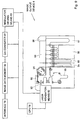
- the digital image processing by which the sub-absorption is corrected is done to the digital image information. For instance, for the magenta dye, in order to delete the density by the sub-absorption in a spectrum area of the blue (optical absorption area of the yellow dye), the image processing is performed in the image processing device (5 of block diagrams in Figure 2).
- the density of the non-image part originates also from the spectral sensitizer which remains without being washed out, irradiation dye added by purposes such as irradiation preventions and filters, colored processing agent not washed out, the fog of the silver halide emulsion and the colored reaction product besides the mask density on the film.
- the contribution of the mask density is very high in the conventional color negative film, so the less or no usage of the mask coupler in our invention has a major reduction in the density of the non image part.
- the color photographic material of this invention preferably has the following gradation.
- the point A on the characteristic curve is defined at a transmittance of (T max - 0.03)
- E a is defined as the value of logarithm of the light exposure at the point A
- the point B on the characteristic curve is defined at a transmittance of (T min + 0.03) (T min is the minimum transmittance)
- E b is defined as the value of logarithm of the light exposure at the point B
- the transmittance value which corresponds to (E a + E b )/2 on the straight line AB is defined as T 0
- the transmittance value which corresponds to (E a + E b )/2 on the said characteristic curve is defined as T 1
- the design of the color negative film of this invention which is characterized by the value T 1
- the ratio of silver/coupler ratio is 150 ⁇ 2000 mol/mol, and, preferably, 300 ⁇ 2000 mol/mol, and most preferably, 700 ⁇ 2000 mol/mol.
- the yellow density of this film is measured using the light which comes through the filter whose transmittance maximum is at 483 nm
- the magenta density is measured using the light which comes through the filter whose transmittance maximum is at 547 nm
- the cyan density is measured using the light which comes through the filter whose transmittance maximum is at 689 nm.
- Fig. 11 is a characteristic curve of a conventional color negative film, whose vertical axis shows the density.
- red sensitive emulsion layer R As an example, the following explanation may be given.
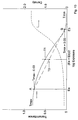
- the characteristic curve of R was shown in Figure 12 by the optical density and the transmittance.
- the gradation is designed to become a straight line almost, when the optical density is plotted in the vertical axis as for a conventional color negative film.
- the density When the density is converted into the transmittance, it becomes a reverse-S shape curve. In the high exposure region, the change in the transmittance according to a change in the exposure becomes very small.
- the detection device used for the scanner converts it into the digital information according to the incident light energy. Because the changes in the transmittance are small in this area, the error of reading is large. It was not possible to expect good accurate gradation reproduction.
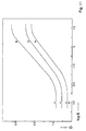
- this invention we make the characteristic curve shown in Figure 13. As a result, there is enough transmittance change over a wide exposure latitude range, and a bigger transmittance change in the high exposure area (in the highlight area in color print).
- This invention shows that the sufficient reading accuracy is obtained even in the high density area where usually the reading accuracy of the scanner becomes deteriorated. Consequently, accurate gradation results in the color prints are obtained.
- the characteristic curve of this invention can be obtained with technological means, which are common for an usual engineer in this industry.
- the exposed layer is made to be a composition of more than two layers, one layer is made to be of high sensitivity, and a silver halide emulsion with soft gradation is used here. Or, more than two kinds of silver halide emulsions with different sensitivity are mixed.
- the emulsion layer which is responsible for this high sensitivity area has a soft gradation characteristics.
- very soft gradation characteristics can be obtained.
- another layer takes charge of the exposure area of low sensitivity , in which the silver halide emulsion has a high gradation characteristics.
- the method to make monodispersed emulsion particle can be adopted, for example.
- very hard gradation characteristics can be also obtained.
- the inter color effect includes the masking effect and the development suppression effect between layers.
- the explanation on the masking effect has already been expressed.
- the development suppression will be explained.
- the development inhibitor is released during the development from the green sensitive layer, and this released inhibitor suppresses the development of the red sensitive layer.
- a DIR coupler is used for this inhibitor releasing compound for this purpose.
- other development inhibiting compounds released in the development can cause this effect, for instance iodine ion etc.
- the cyan dye formation under the white light exposure is suppressed compared with that in the red light exposure. This occurs under the white light exposure, not occurs under the red light exposure.
- the color reproduction system is designed such that the white balance can be reproduced under the white light exposure, therefore, in case of red light exposure, the cyan dye formation is more than that under the white light exposure, which means that the more saturated red reproduction will be obtained on the color paper.
- the magnitude of the inter color effect is preferably as follows: -0.3 ⁇ D(B/R) ⁇ 0.1, -0.3 ⁇ D(G/R) ⁇ 0.2, -0.3 ⁇ D(B/G) ⁇ 0.2, -0.3 ⁇ D(R/G) ⁇ 0.2, -0.3 ⁇ D(G/B) ⁇ 0.2, -0.3 ⁇ D(R/B) ⁇ 0.1, D(B/R) shows the inter color effect from the red sensitive layer to the blue sensitive layer. D(G/R) shows that from the red to the green sensitive layer. D(B/G) shows that from the green to the red sensitive layer. D(G/B) shows that from the blue to the green sensitive layer. D(R/B) shows that from the blue to the red sensitive layer. D(R/B) shows that from the blue to the red sensitive layer.
- the magnitude of the inter color effect here can be obtained as follows.
- inter color effect D(R/G) from the green sensitive layer to the red sensitive layer is obtained as follows.
- a green light (Fuji filter; BPN-55) is exposed to the photographic material with using an optical wedge.
- the flat exposure is given to the photographic material so that the optical density of cyan is D min +0.6 with red light (Fuji filter SC-60).
- the characteristic curve at that time is obtained.
- the optical density is shown in Fig.14.
- Exposure amount Q to which the density is D min + 0.6 by the characteristic curve in the green sensibility layer is obtained. At that time, amount ⁇ x of the reduced concentration in the red sensitive layer is obtained (positive in case of decrease).
- ⁇ x/0.6 is defined to be the magnitude of the inter color effect D(R/G) from the green sensitive layer to the red sensitive layer. Other inter color effects can be similarly obtained. The larger ⁇ x is, the more effective the inter color effect is.
- the reduction or no addition of the DIR coupler or the mask coupler is preferable to make the inter color effect in the range of this invention.
- the DIR coupler releases the development inhibitor.
- the inter color effect in this case the development suppression effect
- these effects can be compensated by the digital image processing described later. Therefore, the reduction or no addition of the DIR coupler and the mask coupler becomes possible.
- the DIR coupler is an expensive compound, and the cost reduction becomes possible by the reduction or no addition.
- the effect of the development inhibition becomes small by reduction or no addition of the DIR coupler. Therefore, the amount of the silver halide emulsion usage can be decreased, the cost reduction becomes possible in addition, and it is preferable.
- the cyan, magenta, and yellow coupler it is preferable for the cyan, magenta, and yellow coupler to reduce weight as much as possible and to decrease the coated quantity of the silver halide.
- the coated amount of silver halide on the color negative film is 0.5-8.0 g-Ag/m 2 . More in particular, 1.0-5.0 g-Ag/m 2 is preferable , 2.0-4.0 g-Ag/m 2 being the most preferred.
- the image information output from the color negative film is digital image information.
- the output device, which outputs the image information can be any suitabel output device, such as a computer monitor, a projector and as preferred embodiment, a printer.
- the printer which inputs the image information to the color positive material can be any positive image printing device which inputs digital information.
- Preferable color positive material is silver halide photographic material such as a silver halide color printing paper, a color diffusion transcript material (color instant photograph), and a heat developing type color diffusion transcript material (Pictrography made by Fuji Photo Film Co., Ltd.), non silver photographic material such as inkjet, sublime dye transcript recording material, heat developing multi-layer material for instance "Thermo auto chrome (Fuji Photo Film Co., Ltd.)".
- silver halide photographic material such as a silver halide color printing paper, a color diffusion transcript material (color instant photograph), and a heat developing type color diffusion transcript material (Pictrography made by Fuji Photo Film Co., Ltd.), non silver photographic material such as inkjet, sublime dye transcript recording material, heat developing multi-layer material for instance "Thermo auto chrome (Fuji Photo Film Co., Ltd.)".
- the silver halide color paper is most preferable.
- the image information is read from the film, it is digitalized, the digital image processing is done, and output to the positive image, the explanation will be given using examples.
- Fig. 1 shows the image processing device used for this invention and the flow of operation of the method of forming the image of this invention.
- the processing equipment of this invention it is preferable that there is a means to detect the kind of the exposed color negative film (It is called the film thereafter) at the start of the process, though it is not a composition required in the invention.
- the film is taken from the left end of this diagram into processing equipment.
- the kind of the film is read (01). It is detected whether it is the film which suits the method of forming the image of this invention ,in a word, a low mask density, and a film with the gradation of this invention or a film of the usual.
- the image processing condition thereafter is set based on this. The processing is done here. This condition can be the above-mentioned common international processing.
- the detection of the kind of the film can be done using the punch sign for the identification which is called DX code recorded on the film.
- the operator occasionally does the selection operation according to a predetermined standard regardless of what the DX code is (04).
- processing of the film of the usual and the processing of the film of this invention can be done with one device by detecting the kind of this film.
- the film is transported in a series of processing tanks in the developing machine. Next, the film to which the color development, the bleaching, fixing, washing or stabilization is performed moves to image information reading device (1).
- the density of each minute area unit (It is called the pixel usually) which composes the image of the film is measured and the image information is read as a density of each pixel.
- the image information is converted into a electric picture signal, and, converted into the digital signal by A/D (analogue/digital) transducer 18 through amplifying device 17.
- this information signal is sent to image processing device 5 through log converter 20.
- the electrical treatment is added to the image information.
- the signal obtained from the film with a gradation of this invention and low D min is converted into the digital image signal with a picture quality similar or better than that obtained from the film with a standard gradation and standard D min .
- the feature in this invention is to be the correction of photographic characteristic by the image processing.
- the image processing operation described here is separately applied for as the Japanese patent application No.8-174022 and No.8-182551.
- the picture signal is output to printer (8), and as a result the positive image is obtained.
- a preferable printer is a printer for the silver halide color print (color print, instant photograph, and heat developing type color diffusion transcript type, etc.), ink jets, the heat sensitive transcript material of sublime type, and the heat sensitive transcript material of wax type, etc.
- This invention method of obtaining a positive image from the film with low D min and the gradation of this invention and the outline of the device were described above. Details are explained further as follows.
- the image obtained from the film used for this invention When converting the image obtained from the film used for this invention into the characteristic value of the photograph for the output by the image processing, it is meant to obtain the image information whose image quality is comparable with the image information obtained by developing a standard usual color negative film.
- the image quality when the objectivity is valued, the image density can be used as a characteristic value.
- the comparable image quality to the standard processing is obtained if the density value is within ⁇ 10% of reference.
- Fig. 2 is a block diagram which shows a basic composition of the image reproduction system by this invention.
- the image reproduction system has the following as shown in Fig. 2.
- Image reader 1 which generates digitalized image data
- Reading color image Image processing device 5 which gives image processing to image data generated with image reader 1
- image output device 8 which reproduces the color image based on image data on which the image processing is given with image processing device 5.
- the image reading can be mainly done by the following three methods:
- This invention can be executed without any trouble by the other two methods, though the explanation thereafter is given on the assumption of this method.
- the reading of image information can adopt the reflection density reading method from the film.
- the image reader 1 can selectively connect the reflection type image reader 30 which reads the color image recorded in color print or the transmittance type image reader 10 which reads the color image recorded on the film with image processing device 5. As a result, both of the color image recorded on the color print and on the film can be reproduced.
- Fig. 4 is a schematic drawing of transmittance type image reader 10 for the color image reproduction system.
- transmittance type image reader 10 can read the color image photoelectronically by irradiating light to the color image on film F, and detecting light which is transmitted. This is provided with the following.
- This transmittance type image reader 10 can read many kinds of films like 135 negative films and 135 positive films advanced photo system (APS) film etc. by exchanging the film carrier not shown in the figure.
- APS advanced photo system
- a halogen lamp is used as the light source 11.
- the light energy can be changed by moving two throttle plate.
- the color separation unit(13) rotates a disk containing three filters, B, G, R, and decomposes light into three colors.
- CCD area sensor 15 possesses the light receiving element of 920 pixels in length and 1380 pixels in width, and can read the image information on the film in the high-resolution evaluation.
- CCD area sensor 15 forwards the image data of the even number field and the image data of the odd number field one after another.
- the transmittance type image reader 10 has the following.
- Amplifier 17 which amplifies picture signal of R, G, and B, analog to digital converter 18 in which picture signal is digitalized, CCD correction means 19 to give the correction due to the difference of sensitivity of each pixel and dark current to the picture signal, and, log converter 20 which converts the image data of R, G, and B into the density data.
- Film F is maintained in carrier 22. It is sent to a fixed position by driving roller 24 driven by motor 23. It is press-hold in the stopped state. When the reading of the color image of one scene is completed, one scene is sent.
- an auto carrier to handle the negative film the one used in the usual mini lab, such as NC135S made by Fuji Photo Film Co., Ltd., can be used. The image which corresponds to the full size, the panorama size, and the power size, etc. can be read.
- a trim carrier in the mini lab is used, the enlargement of 1.4 times becomes possible.
- a reversal carrier the one indicated in the Japanese patent application 7-275359, 7-277455, 7-285015, No.7-271048, and 7-275358 can be used.
- the frame detection sensor 25 detects the concentration distribution of the color image recorded on film F. It outputs the detected density signal to CPU26 which controls transmittance type image reader 10.
- CPU26 calculates the frame position of the color image recorded on film F based on this density signal. It stops the drive of motor 23 when it judged that the frame position of the color image reached a fixed position. You can set up the image reading device at any place, such as an exit of dryer part of the processor, a independent reading position, and the image processing devices or printers.
- Fig. 5 and Fig. 6 show the block diagram of the composition of the image processing device 5.
- the image processing device 5 is made up of interface 48 which can be connected with interface 21 of the transmittance type image reader 10 or interface 41 of the reflection type image reader 30. It is provided with the following.
- the arithmetic operation means 49 which add the value of two adjoining pixel data of each line, average, and make one pixel data, the first line buffer 50a and the second line buffer 50b by which the pixel data in each line is alternately memorized, the first, second, and third frame memory unit 51, 52, and 53 which memorize image data corresponding to color image of film F (Fig. 4).
- the first line buffer 50 and the second line buffer 50b memorize the pixel data of the line of odd number and even number alternately.
- the first reading (Hereafter, it is called pre-scan) with the image reader 1 is done to the color image of one scene recorded on film F. Afterwards, the read image is converted into the digital image data. Based on the image data obtained by this pre-scan, the condition of second reading will be set by the image processing device 5 (Hereafter, it is called real-scan). And, based on the readout condition, the real-scan is executed, and the digital image data which will have the image processing is obtained. To do this processing, the image processing device 5 memorizes the image data obtained by the pre-scan in the first frame memory unit 51.
- the image data obtained by the real-scan is memorized in the second frame memory unit 52 and the third frame memory unit 53.
- Fig. 7 is a block diagram which shows details of the 1st frame memory unit 51 and the 2nd frame memory unit 52 and the 3rd frame memory unit 53.
- the image processing device 5 has the following.
- the 1st frame memory unit 51 and the 2nd frame memory unit 52 and the 3rd frame memory unit 53 are provided with R data memory 51R, G data memory 51G, and B data memory 51B, which memorize image data corresponding to R(red), G(green), and B(blue), R data memory 52R, G data memory 52G, B data memory 52B, R data memory 53R, G data memory 53G, and B data memory 53B respectively to process image data.
- the image data obtained by the pre-scan is memorized in the first frame memory unit 51 as the above-mentioned.
- Image data which is obtained by the real-scan is memorized in the 2nd and 3rd frame memory unit 52.
- Fig. 7 the state that the image data of the pre-scan is input to the first frame memory unit 51 from the input bus 63, and the image data of the second frame memory unit 52 is output to power output bus 64 is shown.
- Image processing device 5 is provided with CPU60 which controls the whole image processing device 5.
- CPU60 can communicate with CPU26 (Fig. 4) which controls transmittance type image reading device 10 and via a communication line (is not shown in the figure). And, it is possible to communicate with CPU which controls image output device 8 described later.
- CPU60 will change the real-scan condition of image reading.
- CPU60 determines the condition of real-scan. It outputs the readout control signal to CPU26 of transmittance type image reading device 10 or to CPU46 of reflectance type image reading device 30(this is not related to this invention).
- CPU26 of the transmittance type image reading device 10 controls the light intensity and the accumulation time of CCD area sensor 15 or CCD line sensor 35, which can be adjusted with light quantity adjustment unit 12 or 34.
- CPU60 Based on the obtained image data, CPU60 outputs the control signal to the image processing means, so as to reproduce the best color image which has the best density, gradation and color on the color paper.
- the image reading condition and the image processing condition (which is decided by CPU60) are memorized in memory 66.
- CPU60 When the operator's instruction is hold, CPU60 does not decide the condition based on the above-mentioned pre-scan image data and control and input various signals based on the kept condition.
- the operator sets various conditions with the input device such as keyboards 69. These conditions are memorized in memory 66. When the operator directs the release of the maintenance of these conditions afterwards, the condition memorized in the memory 66 becomes invalid.
- CPU60 controls the above-mentioned first of all, it refers to the condition memorized in memory 66 and obey it when the condition is memorized. When not memorized, it will decide the conditions based on the pre-scanned image data.
- the operator can read from the DX code, follow a special order of the customer, and direct the condition setting according to the kind of each film.
- the saturation setting is hold for instance and only the automatically decided condition of the sharpness can be used by making it possible to memorize more detailed condition.
- the image processing device 5 has the first image processing means 61 (Fig. 6) to give image processings of the gradation correction, the color conversion, and the concentration conversion, etc. by the look-up table and the matrix operation to the image data in the 2nd frame memory unit 52 and the 3rd frame memory unit 53, so as to reproduce the color image on color paper in the desired density, gradation, and the tone.
- the first image processing means 61 Fig. 6 to give image processings of the gradation correction, the color conversion, and the concentration conversion, etc. by the look-up table and the matrix operation to the image data in the 2nd frame memory unit 52 and the 3rd frame memory unit 53, so as to reproduce the color image on color paper in the desired density, gradation, and the tone.
- the second image processing means 62 (Fig. 6) to give image processing of the gradation correction, the color conversion, and the concentration conversion, etc. in the image data memorized in the first frame memory unit 51 by the look-up table and the matrix operation, so as to reproduce on the screen of CRT described later in the desired picture quality.
- the output of the second frame memory unit 52 and of the third frame memory unit 53 are connected with selector 55.
- the image data of the 2nd frame memory unit 52 or the 3rd frame memory unit 53 is selectively input by selector 55 to the first image processing means 61.
- Fig. 8 is a block diagram by which details of this first image processing means 61 are shown.
- the first image processing means 61 provides with the following.
- Color concentration gradation conversion means 100 to convert the concentration, color, and gradation of image data
- saturation conversion means 101 to convert the saturation data of image data
- digital magnification conversion means 102 to convert the number of pixel data
- frequency processing means 103 to give the image data frequency processing
- dynamic range conversion means 104 to convert the dynamic range.
- These conversion means are usually called pipeline processing. That is, because the processing of the following conversion means are applied at the same time, and immediately after the operation of one conversion means ends, the next conversion starts, the high-speed process is possible.
- the data signal is output from CPU60 to data synthesis means 75.
- Data synthesis means 75 synthesizes the image data which should be synthesized to the obtained image data from synthetic data memory 76. When the instruction signal is not input from keyboard 69 on the other hand, this processing is not executed. Afterwards, the image data is output from data synthesis means 75 to image output device 8.
- the film is designed as follows:
- the level of the saturation emphasizing of the saturation conversion means 101 is set high. That is, in order to compensate the shortage of the inter layer effect, the saturation is corrected in the direction of an increase.
- the foot expansion which affects sensitivity directly is corrected by the saturation conversion means 101 and the combining of dynamic range conversion means 104 and gradation conversion means 100, too.
- the image sharpness is improved by the amendment of the characteristic curve in the toe part and the high density part.
- the image sharpness can be improved.
- frequency processing means 103 That is, the spatial frequency of the image is analyzed. Against the fringe part where the frequency changes greatly and the minute image part where the frequency rises, the emphasizing processing is set.
- the accuracy of the correction of the image information has to be only within 10% of the target value in a concentration. Preferably, it is good within 8%.
- the color balance and the gradation characteristic are judged that the image reproduction can have been done, if the density is within the above-mentioned range.
- the conversion condition of the film is set, you can choose the dataconversion condition by reading the kind of the processed film or choose the condition automatically. Moreover, the operator can specify the conversion processing condition of each film.
- the content of the operation of the image processing device used for the above-mentioned image processing is indicated in Japanese patent applications 8-174022 and No. 8-182551.
- the data bus 65 is installed to the image processing device 5 besides the input bus 63 and out put bus 64 of the 1st frame memory unit 51 and the 2nd frame memory unit 52 and the 3rd frame memory unit 53. The following one is connected with data bus 65.
- CPU60 which controls the entire color image reproduction system
- the memory 66 which contains the operation program of CPU60 and the data of image processing condition
- the hard disk drive 67 which can preserve image data
- CRT68 the keyboard 69
- the communication port 70 connected to other color image reproduction systems through telecommunication lines
- Fig. 9 is a schematic drawing of the image output device 8 for the color image reproduction system which reproduces the color image on color paper based on the image data processed with the image processing device of this invention.
- the image output device 8 is provided with the following one.
- Interface 78 which can be connected to the interface 77 of the image processing device 5 and CPU79 which controls image output device 8
- the image data memory 80 which consists of two or more frame memories which memorize the image data from the image processing device 5
- D/A converter 81 which converts image data into an analog signal
- the laser-irradiation means 82 the modulator driving means 83 by which modulating signal modulates strength of laser light.
- CPU79 can communicate CPU60 of image processing device 5 via the communication line (not shown in the figure).
- Fig. 10 is a schematic drawing of laser-irradiation means 82 shown in Fig. 9.
- the laser-irradiation means 82 is provided with semiconductor laser radiation source 84a, 84b, and 84c.
- the laser light originated by semiconductor laser radiation source 84b is converted into the green laser light of 532 nm in the wave length by wavelength conversion means 85.
- the laser light originated by semiconductor laser radiation source 84c is converted into the blue laser light of 473 nm in the wave length by wavelength conversion means 86.
- Red laser light of the arbitrary wave length between 690 nm and 670 nm which was originated from semiconductor laser radiation source 84a, is injected in 87R, such as AOM(acoustic optical modulator).
- the green laser light into which the wave length is converted by wavelength conversion means 85 is injected in 87G. And, the blue laser light into which the wave length is converted by wavelength conversion means 86 is an incident in 87B.
- the modulating signal is input from the modulator driving means 83 to optical modulator 87R, 87G, and 87B respectively, and the strength of the laser light is modulated according to the modulating signal. In this case, if semiconductor laser radiation source 84a can high-speed operate, by modulating this directly the optical modulator 87R can be omitted.
- the laser light whose strength is modulated by the optical modulator 87R, 87G, and 87B can reflect by reflection mirror 88R, 88G, and 88B, and is incident in the polygon mirror 89. Paper is transported, and the scanning line density is 600 an inch, and each pixel is modulated every 100 nsec.
- the image output device 8 has magazine 91 by which color paper 90 is stored in the roll state. Color paper 90 is transported in the direction of the sub-scanning along a fixed transportation route.
- the color paper whose width is from 89 mm to 210 mm is available. It can be the color paper used in a usual mini lab etc., and you can use a suitable special color paper for high intensity and short time exposure.
- the punching means is provided which can grub the standard hole in the side edge of color paper 90 at every length of frame.
- the transportation of color paper 90 has synchronized with the drive of other means in image output device 8 according to this standard hole.
- the laser light modulated by optical modulator 87R, 87G, and 87B is scanned to the main scanning direction by polygon mirror 89.
- Color paper 90 is exposed through lens 93.
- As for color paper 90 all area are exposed to the laser light because it is transported in the direction of the sub-scanning.
- the transportation speed of color paper 90 in the direction of the sub-scanning is controlled by CPU79 to synchronize with the rotating speed of a main scanning rate of laser light, that is, the rotating speed of polygon mirror 89.
- Color paper 90 exposed by the laser light is sent to development processing part 94.
- the color development, the blix, and washing are performed.
- the color image is reproduced in color paper 90 based on image data to which the image is processed with image processing device 5.
- Color paper 90 to which the color development, the blix treatment, and the washing are performed is sent to dryer part 97. And after drying, based on the standard hole punched onto the side edge of color paper 90, it is cut in length corresponding to the color image with cutter 98. Then, it is sent to sorter 99. Each number of sheets corresponding to one film F is accumulated.
- the sorter is separately applied (Japanese patent applications 2-332146th).
- blix tank 95 Regarding the color development tank 94, blix tank 95, washing tank 96 , dryer part 97, cutter 98, and sorter 99, the ones used in a usual minilab can be used.
- processing method CP47L is adopted in the form of this execution, it is possible to correspond to CP40FA and CP43FA (Processing and the photographic chemicals are both made of the Fuji Photo Film Co., Ltd.).
- the calibration of the image output device can be done. First, using the data memorized, several sets of concentration step patterns of the cyan, magenta, yellow, and gray are exposed. After development, the developed concentration is measured respectively with densitometer automatically. Based on the difference between the concentration which is aimed and measured, the characteristic value given to the modulator to obtain the concentration which should be reproduced is calculated. As a result, reproducing the stable image becomes possible not being influenced by the change of the paper, the device, and the environment etc. The stable image reproduction always becomes possible by controlling such an image output device.
- the ink jet As a material for the output to obtain the positive image, as already described, the ink jet, the sublime type heat sensitive transcript material, the color diffusion transfer, the color electrophotography, the heat developing type silver halide color diffusion transfer, the heat developing type multi layer color di-azo material, and the silver halide color photographic material, etc. can be used. If it is a material which can record the picture signal of electricity of a time series, anyone is acceptable.
- Color paper is especially preferable.
- silver halide color photographic light-sensitive material which is suitable for this out-put material, various conventionally known photographic elements can be employed.
- a transmissive type support or reflective type support is used as a support for the photographic material.
- a transparent film such as a cellulose triacetate film or a polyethylene terephthalate film, and a polyester film composed of 2,6-naphthalenedicarboxylic acid (NDCA) and ethylene glycol (EG) or composed of NDCA, terephthalic acid and EG having provided thereon an information recording layer such as a magnetic layer are preferably employed.
- NDCA 2,6-naphthalenedicarboxylic acid
- EG ethylene glycol
- a laminate composed of plural water-resistant resin layers such as polyethylene layers or polyester layers and containing a white pigment such as titanium oxide in at least one of the resin layers is preferred.
- the water-resistant resin layer contains a fluorescent whitening agent.
- the fluorescent whitening agent may also be dispersed in a hydrophilic colloid layer of the photographic light-sensitive martial.
- Preferred fluorescent whitening agents used include benzoxazole series, cumarin series and pyrazoline series compounds. Fluorescent whitening agents of benzoxazolyl naphthalene series and benzoxazolyl stilbene series are more preferably used.
- the amount of the fluorescent whitening agent to be used is not particularly limited and preferably in a range of from 1 to 100 Mg/m 2 .
- a mixing ratio of the fluorescent whitening agent to be used in the water-resistant resin layer is preferably from 0.0005 to 3% by weight, and more preferably from 0.001 to 0.5% by weight of the resin.
- transmissive type support and a reflective type support each having provided thereon a hydrophilic colloid layer containing a white pigment may be employed.
- a support having a mirror plate reflective metal surface or a secondary diffusion reflective metal surface may be used as the reflective type support.
- a silver chloride or silver chlorobromide emulsion having a silver chloride content of 95 mol% or more is preferably employed as the silver halide emulsion in the color photographic light-sensitive material in view of rapid processing suitability. Further, a silver halide emulsion having a silver chloride content of 98 mol% or more is more preferred. Of these silver halide emulsions, those having a silver bromide localized phase on the surface of silver chloride grain is particularly preferred, since high sensitivity as well as stabilization of photographic characteristics are achieved.
- silver halide emulsion with respect to the reflective type support, silver halide emulsion, heterogeneous metal ion doped in silver halide grain, stabilizer and anti-foggant for silver halide emulsion, chemical sensitization (chemical sensitizer), spectral sensitization (spectral sensitizer), cyan coupler, magenta coupler, yellow coupler, emulsified dispersion method of coupler, color image stabilizer (anti-staining agent), color fading preventing agent, dye (colored layer), gelatin, layer construction of photographic material and pH of coated layer, those described in the patents shown in Table 1 and Table 2 below are preferably used in the present invention.
- chemical sensitization chemical sensitizer
- spectral sensitization spectral sensitizer
- cyan coupler magenta coupler
- yellow coupler emulsified dispersion method of coupler
- color image stabilizer anti-staining agent
- color fading preventing agent dye (colored layer)
- gelatin
- the cyan couplers, magenta couplers and yellow couplers which can be suitably employed in this material also include those described in JP-A-62-215272, page 91 right upper column, line 4 to page 121, left upper column, line 6, JP-A-2-33144, page 3, right upper column, line 14 to page 18, left upper column, last line and page 30, right upper column, line 6 to page 35, right lower column, line 11, and EP-A-355660, page 4, lines 15 to 27, page 5, line 30 to page 28, last line, page 45, lines 29 to 31 and page 47, line 23 to page 63, line 50.
- JP-A-63-271247 The bactericides and anti-mold agents described in JP-A-63-271247 are suitably used in the present invention.
- Gelatin is preferably employed as a hydrophilic colloid in a photographic layer constituting the photographic light-sensitive material.
- An amount of heavy metal, for example, iron, copper, zinc or manganese, which is included as an impurity in gelatin, is preferably not more than 5 ppm, more preferably not more than 3 ppm.
- This photographic light-sensitive material is used in digital scanning exposure system using monochromatic high density light, such as a gas laser, a light emitting diode, a semiconductor laser, a second harmonic generation light source (SHG) comprising a combination of nonlinear optical crystal with a semiconductor laser or a solid state laser using a semiconductor laser as an excitation light source.
- monochromatic high density light such as a gas laser, a light emitting diode, a semiconductor laser, a second harmonic generation light source (SHG) comprising a combination of nonlinear optical crystal with a semiconductor laser or a solid state laser using a semiconductor laser as an excitation light source.
- a semiconductor laser, or a second harmonic generation light source (SHG) comprising a combination of nonlinear optical crystal with a semiconductor laser or a solid state laser.
- at least one of exposure light sources should be a semiconductor laser.
- the spectral sensitivity maximum of the photographic light-sensitive material for the out-put material of this invention can be appropriately set according to the wavelength of the scanning exposure light source to be used.
- an oscillation wavelength of a laser can be made half using an SHG light source comprising a combination of non-linear optical crystal with a solid state laser using a semiconductor laser as an excitation light source or a semiconductor laser, blue light and green light can be obtained. Accordingly, it is possible to have the spectral sensitivity maximum of the photographic light-sensitive material in normal three regions of blue, green and red.
- the exposure time in the scanning exposure is defined as the time necessary to expose the pixel size with the pixel density being 400 dpi, and preferred-exposure time is 10-4 second or less and more preferably 10-6 second or less.
- the color negative film of this invention is a type to which the gradation and D min are changed from the general color negative film provided from each maker. And, the one with the reduced inter color effect is preferable.
- a typical example of the light-sensitive materials of the present invention is a silver halide photographic light-sensitive material having, on the support, at least one light-sensitive layer constituted by a plurality of silver halide emulsion layers which are sensitive to the same color but which have different sensitivities or speeds.
- the light-sensitive layer is a unit light-sensitive layer which is sensitive to any one of blue light, green light and red light and, in a multi-layered silver halide color photographic light-sensitive material, a generally adopted order of the unit light-sensitive layers from the support is red-sensitive layer, a green-sensitive layer and a blue-sensitive layer.
- Non-light-sensitive layers can be formed between the silver halide light-sensitive layers and as the uppermost layer and the lowermost layer. These non-light-sensitive layers can contain, e.g., couplers, DIR compounds, color mixture preventives described later.
- a two-layered structure of high-speed and low-speed emulsion layers can be preferably arranged such that the sensitivity or speed is sequentially decreased toward a support as described in West German Patent 1,121,470 or British Patent 923,045.
- layers may be arranged such that a low-speed emulsion layer is formed remotely from a support and a high-speed layer is formed close to the support.
- layers may be arranged from the remotest side from a support in an order of low-speed blue-sensitive layer (BL)/high-speed blue-sensitive layer (BH)/high-speed green-sensitive layer (GH)/low-speed green-sensitive layer (GL)/high-sensitive red-sensitive layer (RH)/low-speed red-sensitive layer (RL), or BH/BL/GL/GH/RH/RL, or BH/BL/GH/GL/RL/RH.
- BL low-speed blue-sensitive layer
- BH high-speed blue-sensitive layer
- GH high-speed green-sensitive layer
- GL low-speed green-sensitive layer
- RH red-sensitive layer
- RL low-speed red-sensitive layer
- layers may be arranged from the remotest side from a support in an order of blue-sensitive layer/GH/RH/GH/RL as described in JP-B-55-34932.
- layers may be arranged of from the remotest side from a support in an order of blue-sensitive layer/GL/RL/GH/RH as described in JP-A-56-25738 and JP-A-62-63936.
- three layers may be arranged such that a silver halide emulsion layer having the highest sensitivity is arranged as an upper layer, a silver halide emulsion layer having sensitivity lower than that of the upper layer is arranged as an intermediate layer, and a silver halide emulsion layer having sensitivity lower than that of the intermediate layer is arranged as a lower layer, i.e., the three layers having different sensitivities may be arranged such that the sensitivity is sequentially decreased toward the support.
- the light-sensitive material comprises the three layers having different sensitivities or speed
- these layers may be arranged from far to near the support in the order of medium-speed emulsion layer/high-speed emulsion layer/low-speed emulsion layer within a layer sensitive to one and the same color sensitivity as described in JP-A-59-202464.
- an order of high-speed emulsion layer/low-speed emulsion layer/medium-speed emulsion layer, or an order of low-speed emulsion layer/medium-speed emulsion layer/high-speed emulsion layer may be adopted.
- the arrangement can be changed as described above, even when four or more layers are formed.
- a donor layer (CL) having different spectral sensitivity distribution from that of a main light-sensitive layer such as BL, GL and RL and having interlayer effect is preferably arranged adjacent to or in the vicinity of the main light-sensitive layer.
- a preferable silver halide to be used in photographic emulsion layers of the photographic light-sensitive material of the present invention is silver iodobromide, silver iodochloride or silver iodochlorobromide containing about 30 mol% or less of silver iodide.
- a particularly preferable silver halide is silver iodobromide or silver iodochlorobromide each containing about 2 mol% to about 10 mol% of silver iodide.
- the silver halide grains contained in the photographic emulsion may be in the form of regular crystals, such as cubes, octahedrons and decatetrahedrons, irregular crystals, such as spheres and tabulars, crystals having defects such as twin planes, or composite shapes thereof.
- the grain sizes of the silver halide may range from fine grains having a grain diameter of about 0.2 ⁇ m or less or to large grains having a diameter of the projected area of a grain of up to about 10 ⁇ m.
- the silver halide emulsion may be a polydisperse emulsion or a monodisperse emulsion.
- the silver halide photographic emulsion usable in the present invention can be prepared by the methods described, for example, in Research Disclosure (hereinafter abbreviated to RD) No. 17643 (December 1978), pages 22-23, "I. Emulsion Preparation and Types”; RD No. 18716 (November 1979), page 648, and RD No. 307105 (November 1989), pages 863-865; P. Glafkides, "Chimie et Physique Photographiques", Paul Montel, 1967; G.F. Duffin, "Photographic Emulsion Chemistry", Focal Press 1966; and V.L. Zelikman et al., “Making and Coating Photographic Emulsion", Focal Press, 1964.
- tabular grains having an aspect ratio of about 3 or more can also be used in the present invention.
- the tabular grains can be easily prepared by the methods described in Gutoff, "Photographic Science and Engineering", Vol. 14, pp. 248-257 (1970); U.S. Patents 4,434,226; 4,414,310; 4,433,048 and 4,439,520, and British Patent 2,112,157.
- the crystal structure may be uniform, may have different halogen compositions in its interior and exterior, or may be layered structure.
- silver halide having different compositions may be joined by an epitaxial junction, or a compound other than a silver halide such as silver rhodanide or lead oxide may be joined.
- a mixture composed of grains having various crystal forms may also be used.
- the above-mentioned emulsion needs to be a negative-type emulsion, although it may be of a surface latent image type which forms a latent image mainly on the surface of the grains, an inner latent image type which forms a latent image inside the grains, or other type which forms a latent image both inside and outside the grain.
- the emulsion belonging to the inner latent image type may be of the inner latent image type having a core/shell structure described in JP-A-63-264740, the method for making which emulsion is described in JP-A-59-133542.
- the thickness of the shell for this emulsion is preferably 3 to 40 nm and most preferably 5 to 20 nm, although the thickness varies depending on processing conditions for development and the like.
- the silver halide Prior to the use of the light-sensitive material of present invention, the silver halide usually undergoes a chemical ripening, a physical ripening, and a spectral sensitization steps.
- the additives which are used at such steps are described in RD No. 17643, RD No. 18716 and RD No. 307105 and are summarized later in a table with the indications of the relevant places of description.
- a mixture of two or more emulsions which differ from one another in at least one of the characteristics selected from the group consisting of grain size, grain size distribution, halogen composition, shape of grain and sensitivity, can be used in the same layer.
- non-light-sensitive silver halide fine grains mean the silver halide fine grains which are not sensitized in the imagewise exposure for forming a dye image and are substantially undeveloped when processed for development.
- the non-light-sensitive silver halide fine grains are not fogged in advance.
- the fine-grain silver halide has a silver bromide content of 0 to 100 mol%. If necessary, the fine-grain silver halide may further contain silver chloride and/or silver iodide. Preferred silver iodide content is 0.5 to 10 mol%.
- the average grain diameter (average value of the equivalent-circle diameter of projected area) of the fine-grain silver halide is preferably 0.01 to 0.5 ⁇ m, and more preferably 0.02 to 0.2 ⁇ m.
- the fine-grain silver halide can be prepared by the same method as that for a conventional light-sensitive silver halide. No optical sensitization or spectral sensitization is necessary for the surface of the grains of the silver halide. However, it is preferable to add to the silver halide grains a known stabilizer such as a triazole compound, an azaindene compound, a benzothiazole compound, a mercapto compound or a zinc compound, before the silver halide is added to a coating solution.
- a layer, which contains the fine-grain silver halide may further contain colloidal silver.
- the photographic additives usable in the present invention are also described in Research Disclosures (l.c.) and the following table 3 shows the additives together with the relevant places of description in the different RD's: Additives RD17643 RD18716 RD307105 1. Chemical sensitizer p23 p648,r.c. p866 2. Sensitivity increasing agent p648,r.c. 3. Spectral sensitizer Super sensitizer p23-24 p648, r.c. p649,r.c. p866-868 4. Brightener p24 p647,r.c. p868 5. Light absorber Filter dye, Ultraviolet absorbent p25-26 p649, r.c.
- Couplers can be used in the light-sensitive material of the present invention, and the following couplers are particularly preferable.
- Yellow couplers couplers represented by Formulas (I) and (II) in European Patent (hereinafter referred to as EP 502,424A; couplers (particularly Y-28 on page 18) represented by Formulas (1) and (2) in EP 513,496A; a coupler represented by Formula (I) in claim 1 of EP 568,037A; a coupler represented by Formula (I) in claim 1, lines 45 to 55, in U.S.
- Patent 5,066,576 a coupler represented by Formula (I) in paragraph 0008 of JP-A-4-274425; couplers (particularly D-35 on page 18) described in claim 1 on page 40 in EP 498,381A1; couplers (particularly Y-1 (page 17) and Y-54 (page 41)) represented by Formula (Y) on page 4 in EP 447,969A1; and couplers (particularly II-17 and II-19 (column 17) and II-24 (column 19)) represented by Formulas (II) to (IV) in column 7, lines 36-58, in U.S. Patent 4,476,219.
- Magenta couplers JP-A-3-39737 (L-57 (page 11, lower right column), L-68 (page 12, lower right column), and L-77 (page 13, lower right column); (A-4)-63 (page 134), and (A-4)-73 and (A-4)-75 (page 139) in EP 456,257; M-4 and M-6 (page 26), and M-7 (page 27) in EP 486,965; M-45 (page 19) in EP 571,959A; (M-1) (page 6) in JP-A 5-204196; and M-22 in paragraph 0237 of JP-A-4-362631.
- Cyan couplers CX-1, CX-3, Ck-4, CX-5, CX-11, CX-12, CX-14, and CX-15 (pages 14 to 16) in JP-A-4-204843; C-7 and C-10 (page 35), C-34 and C-35 (page 37), and (I-1) and (I-17) (pages 42 and 43) in JP-A-4-345; and couplers represented by Formula (Ia) and (Ib) described in claim 1 of JP-A-6-67385.
- Polymer couplers P-1 and P-5 (page-11) in JP-A-2-44345.
- Couplers for forming a colored dye having a proper diffusibility are preferably those described in U.S. Patent 4,366,237, British Patent 2,125,570, EP 96,873B and West German Laid-open Patent Application 3,234,533.
- Couplers for correcting unnecessary absorption of a colored dye are yellow colored cyan couplers (particularly YC-86 on page 84) represented by Formulas (CI), (CII), (CIII) and (CIV) described on page 5 in EP 456,257A1; yellow colored magenta couplers ExM-7 (page 202), Ex-1 (page 249) and Ex-7 (page 251) in EP 456,257A; magenta colored cyan couplers CC-9 (column 8) and CC-13 (column 10) described in U.S. Patent 4,833,009; (2) (column 8) in U.S. Patent 4,838,136; and colorless masking couplers (particularly compound examples on pages 36 to 45) represented by Formula (A) described in claim 1 of WO 92/11,575. But these colored couplers are not preferably used in this invention as mentioned before.
- Example of a compound (including a coupler) which reacts with a developing agent oxidized form and releases a photographically useful compound residue are as follows.
- Development inhibitor release compounds compounds (particularly T-101 (page 30), T-104 (page 31), T-113 (page 36), T-131 (page 45), T-144 (page 51) and T-158 (page 58)) represented by Formulas (I), (II), (III) and (IV) described on page 11 in EP 378,236A; compounds (particularly D-49 (page 51)) represented by Formula (I) described on page 7 in EP 436,938A2; compounds (particularly (23) (page 11)) represented by Formula (I) in EP 568,037A; compound (particularly I-(1) on page 29) represented by Formulas (I), (II) and (III) described on pages 5 and 6 in EP 440,195A2; (But these compounds are not preferably used in this invention as mentioned before.) bleaching accelerator release compounds: compound (particularly (60) and (61) on page 61
- Patent 4,555,478 leuco dye release compounds; compounds 1 to 6 in columns 3 to 8 of U.S. Patent 4,749,641; fluorescent dye release compounds; compounds (particularly compounds 1 to 11 in columns 7 to 10) represented by COUP-DYE described in claim 1 of U.S. Patent 4,774,181; development accelerators of fogging agent release compounds; compounds (particularly compound (I-22) in column 25) represented by Formulas (1), (2) and (3) described in column 3 of U.S.
- additive other than couplers are as follows:
- Dispersants of an oil-soluble organic compound P-3, P-5, P-16, P-19, P-25, P-30, P-42, P-49, P-54, P-55, P-66, P-81, P-85 and P-93 (pages 140 to 144) in JP-A-62215272; impregnating latexes of an oil-soluble organic compound: latexes described in U.S. Patent 4,199,363; developing agent oxidized form scavengers: compounds (particularly I-(1), I-(2), I-(6) and I-(12) (columns 4 and 5)) represented by Formula (I) in column 2, lines 54 to 62, in U.S.
- Patent 4,923,790 stabilizers and aitifoggants: I-1 to (14), particularly I-1, 60, (2) and (13), in columns 6 to 16 of U.S. Patent 4,923,793, and compounds 1 to 65, particularly compound 36, in columns 25 to 32 of U.S.
- Patent 4,268,622 and compounds (1) to (31) (columns 2 to 9) represented by Formulas (I) in U.S. Patent 4,923,788; and UV absorbents: compounds (18b) to (18r) and 101 to 427 (pages 6 to 9) represented by Formulas (1) in JP-A-46-3335, compounds (3) to (66) (pages 10 to 44) represented by Formula (I) and compounds HBT-1 to HBT-10 (page 14) represented by Formula (III) in EP 520,938A, and compounds (1) to (31) (columns 2 to 9) represented by Formula (1) in EP 521,823A.
- the present invention can be applied to various color light-sensitive materials.
- the present invention is also suited to film units with lens described in-JU-B-2-32615 and JU-B-3-38784 ("JU-B" means Published Examined Japanese Utility Model Application).
- a support which can be suitably used in the present invention is described in, e.g., RD No. 17643, page 28, RD No. 18716, from right column, page 647, to left column, page 648, and RD No. 307105, page 879.
- the sum total of film thickness of all hydrophilic colloid layers on the side having the emulsion layers is preferably 28 ⁇ m or less, more preferably 23 ⁇ m or less, particularly preferably 18 ⁇ m or less, and most preferably 16 ⁇ m or less.
- a film swell speed T1/2 is preferably 30 seconds or less, and more preferably 20 seconds or less.
- T1/2 is defined as a time which the film thickness requires to reach 1/2 of a saturation film thickness which is 90% of a maximum swell film thickness reached when processing is performed by using a color developer at 300C for 3 min and 15 seconds.
- the film thickness means the thickness of a film measured under moisture conditioning at a temperature of 250° C and a 55% relative humidity (two days).
- T1/2 can be measured by using a swell meter described in Photographic Science Engineering, A. Green et al., Vol. 19, No. 2, pp. 124-129. T1/2 can be adjusted by adding film hardening agent to gelatin as a binder or changing ageing conditions after coating.
- the swell ratio is preferably 150 to 400%. The swell ratio can be calculated from the maximum swell film thickness under the conditionings mentioned above by using (maximum swell film thickness-film thickness) / film thickness.
- hydrophilic colloid layers having a total dried film thickness of 2 to 20 ⁇ m are preferably formed on the side opposite to the side having emulsion layers.
- the back layers preferably contain, e.g., the light absorbent, the filter dye, the ultraviolet absorbent, the antistatic agent, the film hardener, the binder, the plasticizer, the lubricant, the coating aid, and the surfactant, described above.
- the swell ratio of the back layer is preferably 150 to 500%.
- the light-sensitive material of the present invention can be processed for development by a conventional method described in aforesaid RD No. 17643, pages 28 and 29, RD No. 18716, page 651, from left column to right column, and RD No. 307105, pages 880 and 881.
- the color developing solution of the present invention may contain the compounds described in JP-A-4-121739, page 9, upper right column, line 1 to page 11, lower left column, line 4.
- Preferred developing agents for the rapid processing are 2methyl-4-(N-ethyl-N-(2-hydroxyethyl) amino) aniline, 2methyl-4- (N-ethyl-N- (3-hydroxypropyl)amino)aniline and 2-methyl-4-(N-ethyl-N-(4-hydroxybutyl)amino)aniline.
- the concentration of these color developing agents is preferably 0.01 to 0.08 mol, more preferably 0.015 to 0.06 mol, and most preferably 0.02 to 0.05 mol per liter of the color developing solution.
- the concentration of these color developing agents in a replenisher solution of the color developing solution is preferably 1.1 to 3 times, more preferably 1.3 to 2.5 times, the concentration in the color developing solution.
- the color developing solution of the present invention may contain a hydroxylamine as a general purpose preservative.
- a hydroxylamine as a general purpose preservative.
- preferable preservatives are hydroxylamine derivatives having substituents such as alkyl, hydroxyalkyl, sulfoalkyl and carboxyl groups, preferred examples of which are N,N-di(sulfoethyl)hydroxylamine, monomethylhydroxylamine, dimethylhydroxylamine, monoethylhyroxylamine, diethylhydroxylamine and N,N-di(carboxylethyl)hydroxylamine.
- N,N-di(sulfoethylhydroxylamine is particularly preferable.
- any of these derivatives may be used in combination with hydroxylamine, preferably one, or two or more of these derivatives are used instead of hydroxylamine.
- the concentration of the preservative is preferably 0.02 to 0.2 mol, more preferably 0.03 to 0.15 mol, and most preferably 0.04 to 0.1 mol per liter of the color developing solution.
- the concentration of the preservative in a replenisher solution of the color developing solution is 1.1 to 3 times the concentration in the mother solution (i.e., the solution in the processing tank).
- the color developing solution contains a sulfite.
- the concentration of the sulfite is preferably 0.01 to 0.05 mol and particularly preferably 0.02 to 0.04 mol per liter of the color developing solution.
- the concentration of the sulfite in a replenisher solution of the color developing solution is 1.1 to 3 times the concentration mentioned above.
- the pH value of the color developing solution is preferably 9.8 to 11.0 and particularly preferably 10.0 to 10.5.
- the pH value of a replenisher solution of the color developing solution is set to a value preferably 0.1 to 1.0 above the above-mentioned values.
- a known buffer solution such as a carbonate, a phosphate, a sulfosalicylate or a borate is used.
- the quantity of replenisher of the color developing solution is preferably 80 to 1,300 mL per m 2 of the light-sensitive material. From the viewpoint of reducing the polluting load to environment, the quantity should be reduced and is preferably 80 to 600 mL, more preferably 80 to 400 mL.
- the bromide ion concentration in the color developing solution is usually 0.01 to 0.06 mol per liter of the color developing solution.
- the bromide ion concentration is set to 0.015 to 0.03 mol per liter of the color developing solution for the purpose of fog inhibition and enhancement of discrimination while maintaining the sensitivity and for overcoming the problem of graininess.
- the replenisher solution needs to contain the bromide ions at the concentration given by the following equation; provided that the replenisher solution preferably contains no bromide ion if the calculated value C is negative.
- C A -W/V
- development accelerators such as pyrazolidones represented by 1-phenyl-3-pyrazolidone or 1-phenyl-2-methyl-2-hydroxymethyl-3-pyrazolidone, and thioether compounds represented by 3,6-dithia-1,8-octanediol, as a means for increasing the sensitivity.
- a preferable bleaching agent has a redox potential of 150 mV or more.
- Preferred examples of the bleaching agents are described in JP-A-5-72694 and JP-A-5-173312. Particularly preferred examples are 1,3-diaminopropanetetraacetic acid and ferric complex salts of the compounds shown as example 1 in JP-A-5-173312.
- the ferric complex salts of the compounds described in JP-A-4-251845, JP-A-268552, EP 588,289, EP 591-, 934 and JP-A-6-208213 is a bleaching agent to increase the biodegradability of the bleaching agent.
- the concentration of the bleaching agent is preferably 0.05 to 0.3 mol per liter of the solution having a bleaching power.
- the concentration is set to 0.1 to 0.15 mol in order to reduce the discharge amount to environments.
- the solution having a bleaching power is a bleaching solution, it is desirable that the solution contain the bromide ions at a concentration of 0.2 to 1 mol, preferably 0.3 to 0.8 mol, per liter of the solution.
- the replenisher solution of the solution having a bleaching power needs to have concentration of the components shown below which are basically calculated by the following equation. As a result, the concentration in the mother solution can be maintained at a constant value.
- C R C T ⁇ (V 1 + V 2 )/V 1 + C p
- the bleaching solution contain a pH buffering agent, preferred examples of which are low-odor dicarboxylic acids such as succinic acid, maleic acid, malonic acid, glutaric acid and adipic acid. It is also preferable to use known bleaching accelerators described in JP-A-53-95630, RD No. 17129 and U.S. Patent 3,893,858.
- the bleaching solution be supplied with 50 to 1,000 mL, preferably 80 to 500 mL, and most preferably 100 to 300 mL of a replenisher solution of the bleaching solution per m 2 of the light-sensitive material. Further, it is preferable that the bleaching solution be aerated.
- the solution having a fixing power preferably contains the compounds represented by the Formulas (I) and (II) in JP-A-6-301169 singly or as a combination.
- a sulfinic acid such as p-toluenesulfinic acid salt, described in JP-A-1-224762.
- the solution having a bleaching power or a fixing power When viewed from the enhancement of the desilvering capability, it is desirable that the solution having a bleaching power or a fixing power contain ammonium as a cation. However, it is preferable to decrease the ammonium content of the solution or to make the solution ammonium-free from the viewpoint of the reduction of the environmental pollution.
- the quantity of replenisher at a bleach-fixing step or fixing step is 100 to 1,000 mL, preferably 150 to 700 mL, and most preferably 200 to 600 mL per m 2 of the light-sensitive material.
- the bleach-fixing step or fixing step is provided with an in-line or off-line silver recovery unit so that the silver is recovered.
- an in-line unit is used, the quantity of replenisher can be reduced, because the silver concentration in the solution in the bath becomes smaller owing to the treatment. meanwhile, it is also desirable to remove the silver by means of an off-line unit so that the residual solution is re-used as-a replenisher solution.
- the bleach-fixing step or fixing step may comprises a plurality of processing tanks, which are preferably arranged by a multistage counter-current method employing cascade piping. Because of the balance with the size of the processor, in general a two-tank cascade structure is efficient wherein the ratio of the processing time between the fore tank and the rear tank is preferably in the range of 0.5:1 to 1:0.5 and particularly preferably in the range of 0.8:1 to 1:0.8
- the bleach-fixing solution or fixing solution preferably contains a free chelating agent which is not in the form of a complex with a metal.
- chelating agents are preferably biodegradable chelating agents previously described in connection with the bleaching solution.
- JP-A-4-125558, page 12, lower right column, line 6 to page 13, lower right column, line 16 can be preferably applied to the water-washing and stabilizing step.
- the stabilizing solution with an azolylmethylamine described in EP 504,609 and EP 519,190 or an N-methylolazole described in JP-A-4-362943 as formaldehyde substitute compounds and to make the magenta coupler bi-equivalent for the purpose of utilizing a solution of a surface active agent free of a formaldehyde-based image stabilizer.
- the stabilizing solution described in JP-A-6-289559 may be preferably used.
- the quantity if replenisher of washing water or of the stabilizing solution is 80 to 1,000 mL, preferably 100 to 500 mL, and most preferably 150 to 300 mL per m 2 of the light-sensitive material both from securing the water-washing or stabilizing function and from the reduction of waste solution in view of the environmental preservation.
- a known mildewproofing agent such as thiabendazole, 1,2-benzoisothiazoline-3-one or 5-chloro-2-methylisothiazoline-3-one, an antibiotic, such as gentamycin, and deionized water which has been deionization-treated with an ion-exchange resin in order to prevent the growth of bacteria or mildew.
- an antibiotic such as gentamycin
- deionized water which has been deionization-treated with an ion-exchange resin
- the reverse osmosis membrane is preferably a low-pressure reverse osmosis membrane.
- the processing of the present invention it is particularly preferable to compensate for the evaporation of the processing solutions in accordance with the method described in Journal of Technical Disclosure No. 94-4992 of The Japan Institution of Innovation and Invention (hereinafter abbreviated as JIII).
- JIII Journal of Technical Disclosure No. 94-4992 of The Japan Institution of Innovation and Invention
- the water to be used to compensate for evaporation is preferably taken from a replenishment tank to the water-washing bath, and the replenishing water is preferably deionized water.
- processing agents described in the above-mentioned Journal of Technical Disclosure, page 3, right column, line 15 to page 4, left column, line 32 are desirable for use in the present invention.
- a desirable processor using these processing agents is the film processor described in the above-mentioned Journal of Technical Disclosure, page 3, right column, lines 22 to 28.
- the supply form of a processing agent to be used in the present invention can be any of a liquid having the concentration of a solution in use, a concentrated liquid, a granule, a powder, a pellet, a paste and an emulsion.
- these processing agents are a liquid contained in a low-oxygen-permeability vessel disclosed in JP-A-63-17453, vacuum-packaged powders or granules disclosed in JP-A-4-19655 and JP-A-4-230748, granules containing a water-soluble polymer disclosed in JP-A-4-221951, pellets disclosed in JP-A-51-61837 and JP-A-6-102628, and a processing agent in the form of a paste disclosed in PCT National Publication No. 57-500485. Any of these forms can be preferably used. However, in respect of simplicity in use, the use of a liquid already prepared to have a concentration in use is preferable.
- the material of vessels containing these processing agents can be any of polyethylene, polypropylene, polyvinylchloride, polyethylene terephthalate and nylon. These materials can be used singly or in the form of a composite material. These materials are so selected as to meet the level of a necessary oxygen permeability. Low-oxygen-permeability materials are suited to a solution such as a color developing solution which is readily oxidized. Practical examples are polyethylene terephthalate and a composite material of polyethylene and nylon. The thickness of a vessel made from any of these materials is 500 to 1,500 ⁇ m.
- the oxygen permeability is preferably 20 mL/m 2 .24 hrs.atm or less.
- the control bath or the final bath contains the image stabilizing agent.
- image stabilizing agents which are formalin, sodium formaldehydebisulfite and N-methylolazole
- preferable is sodium formaldehydebisulfite or an N-methylolazole, N-methyloltriazole in particular, from the viewpoint of working environments.
- the techniques, which were stated previously concerning the color developing solution, bleaching solution, fixing solution and washing water for the processing of color negative film can also be preferably used for the processing of the color reversal film.
- preferred processing agents for color reversal films include E-6 Processing Agent manufactured by Eastman Kodak Co., Ltd. and CR-56 Processing Agent manufactured by Fuji Film Co., Ltd.
- the magnetic recording layer used in the present invention is formed by coating the surface of a support with an aqueous or organic solvent-based coating solution which is prepared by dispersing magnetic grains in a binder.
- the magnetic grains used in the present invention can be ferromagnetic iron oxide such as ⁇ Fe 2 O 3 , Co-deposited ⁇ Fe 2 O 3 , Co-deposited magnetite, Co-containing magnetite, ferromagnetic chromium dioxide, a ferromagnetic metal, a ferromagnetic alloy, Ba ferrite of a hexagonal system, Sr ferrite, Pb ferrite and Ca ferrite.
- Co-deposited ferromagnetic iron oxide such as Co-deposited ⁇ Fe 2 O 3 is preferable.
- the grain can take the shape of any of, e.g., a needle, a rice grain, a sphere, a cube and plate.
- a specific surface area is preferably 20 m 2 /g or more, and more preferably 20 m 2 /or more as S BET .
- the saturation magnetization ( ⁇ s) of the ferromagnetic substance is preferably 3.0 ⁇ 10 4 to 3.0 ⁇ 10 5 A/m, and most preferably 4.0 ⁇ 10 4 to 2.5 ⁇ 10 5 A/m.
- a surface treatment can be performed for the ferromagnetic grains by use of silica and/or alumina or an organic material. Also, the surface of the ferromagnetic-grains can be treated with a silane coupling agent or a titanium coupling agent as described in JP-A-6-161032. Ferromagnetic grains, whose surface is coated with an inorganic or organic substance, described in JP-A-4-259911 and JP-A-5-81652 can also be used.
- thermoplastic resin As the binder together with the magnetic grains, it is possible to use a thermoplastic resin, a thermosetting resin, a radiation-curable resin, a reactive resin, an acid-, alkali- or bio-degradable polymer, a natural polymer (e.g., a cellulose derivative and a saccharide derivative) and their mixtures described in JP-A-219569.
- Tg of the resin is -40°C to 300°C, and its weight average molecular weight is 2,000 to 1,000,000.
- the resin examples include vinyl copolymer, cellulose derivatives, such as cellulose diacetate, cellulose triacetate, cellulose acetatepropionate, cellulose acetatebutylate and cellulose tripropionate, an acrylic resin, and a polyvinylacetal resin.
- Gelatin is also preferable.
- Cellulose di(tri)acetate is particularly preferable.
- the binder can be hardened by the addition of an epoxy, aziridine, or isocyanate crosslinking agent.
- isocyanate crosslinking agent examples include isocyanates, such as tolylenediisocyanate, 4,4'-diphenylmethanediisocyanate, hexamethylenediisocyanate and xylylenediisocyanate, reaction products of these isocyanates and polyalcohols (e.g., a reaction product of 3 mols of tolylenediisocyanate and 1 mol of trimethylolpropane), and a polyisocyanate produced by condensation of any of these isocyanates.
- isocyanates such as tolylenediisocyanate, 4,4'-diphenylmethanediisocyanate, hexamethylenediisocyanate and xylylenediisocyanate
- reaction products of these isocyanates and polyalcohols e.g., a reaction product of 3 mols of tolylenediisocyanate and 1 mol of trimethylolpropane
- the use of a kneader, a pin-type mill or an annular mill is preferable, and a combination of them is also preferable.
- Dispersants described in JP-A-5-088283 and other known dispersants can be used.
- the thickness of the magnetic recording layer is 0.1 to 10 ⁇ m, preferably 0.2 to 5 4 m, and more preferably 0.3 to 3 ⁇ m.
- the weight ratio of the magnetic grains to the binder is preferably 0.5:100 to 60:100, and more preferably 1:100 to 30;100.
- the coating amount of the magnetic grains is 0.005 to 3 g/m 2 , preferably 0.01 to 2 g/m 2 , most preferably 0.02 to 0.5 g/m 2 .
- the transmission yellow density of the magnetic recording layer is preferably 0.01 to 0.50, more preferably 0.03 to 0.20, and most preferably 0.04 to 0.15.
- the magnetic recording layer can be formed in the whole area of, or in the shape of stripes on, the back surface of a photographic support by coating or printing.
- the magnetic recording layer can be formed by any coating method using, e.g., an air doctor, a blade, an air knife, squeezing, impregnation, a reverse roll, a transfer roll, gravure, kissing, casting, spray, dipping, a bar or extrusion.
- a coating solution described in JP-A-5-341436 is preferable.
- the magnetic recording layer may have additional functions such as improvement of lubricating property, adjustment of curling, electrostatic charge prevention, adhesion prevention and polish of head. Alternatively, an additional functional layer may be formed which performs these functions.
- a preferable polishing agent contains at least one type of aspherical inorganic grains which have a Mohs hardness of 5 or more.
- the composition of the aspherical inorganic grain is preferably an oxide, such as aluminum oxide, chromium oxide, silicon dioxide and titanium dioxide, carbide, such as silicon carbide and titanium carbide, or a fine powder of diamond.
- the surfaces of the grains constituting these polishing agents can be treated with a silane coupling agent or a titanium coupling agent.
- These grains can be added to the magnetic recording layer, or the magnetic recording layer can be overcoated with a layer containing these grains (e.g., as a protective layer or a lubricating layer).
- the binder to be used together with the grains can be of any of those described above and is preferably the same binder as in the magnetic recording layer.
- Light-sensitive materials having the magnetic recording layer are described in U.S. Patents 5,336,589; 5,250,404; 5,229,259 and 5,215,874, and EP 466,130.
- the polyester used in the present invention is made up of a diol and an aromatic dicarboxylic acid as essential components.
- the aromatic dicarboxylic acid include 2,6-, 1,5-, 1,4- and 2,7-naphthalenedicarboxylic acid, terephthalic acid, isophthalic acid and phthalic acid.
- the diol include diethyleneglycol, triethyleneglycol, cyclohexanedimethanol, bisphenol A and bisphenol.
- polystyrene resin examples include polyethylene terephthalate, polyethylene naphthalate and polycyclohexanedimethanol terephthalate.
- the polyester containing 50 to 100 mol% of 2,6-naphthalenedicarboxylic acid is particularly preferable. Polyethylene 2,6-naphthalate is most preferable among these polymers.
- the average molecular weight ranges between 5,000 and 200,000.
- Tg of the polyesters for use in the present invention is 50°C or higher, preferably 90°C or higher.
- the polyester support is heat-treated at a temperature within the range of from 40°C to less than Tg, more preferably at a temperature within the range of from Tg - 20°C to less than Tg.
- the heat treatment can be performed at a fixed temperature within this range or can be performed together with cooling.
- the heat-treatment time is 0.1 to 1,500 hours, more preferably 0.5 to 200 hours.
- the heat treatment can be performed for a roll-like support or while the support is conveyed in the form of a web. Fine undulations (e.g., coating the surface with electroconductive inorganic fine grains such as SnO 2 or Sb 2 O 5 ) may be given to the surface to improve the surface condition.
- heat treatments can be performed at any stage, for example, after support film formation, after surface treatment, after back layer coating (e.g., an antistatic agent or lubrication agent) and after the application of an undercoat.
- a preferable timing for the heat treatment is after the application of the antistatic agent.
- an ultraviolet absorbent may be incorporated into this polyester.
- the prevention of light piping can be achieved by incorporating the polyester with a dye or pigment, such as Diaresin manufactured by Mitsubishi Chemical Industries, Ltd. or Kayaset manufactured by Nippon Kayaku Co., Ltd., which is commercially available as an additive to polyester.
- a surface treatment of the support in order to increase the bonding strength between the support and the light-sensitive material constituting layers.
- the surface treatment are surface activating treatments which include a chemical treatment, a mechanical treatment, a corona discharge treatment, a flame treatment, an ultraviolet treatment, a high-frequency treatment, a glow discharge treatment, an active plasma-treatment, a laser treatment, a mixed acid treatment and an ozone oxidation treatment.
- Preferred surface treatments are the ultraviolet irradiation treatment, the flame treatment, the corona treatment and the glow treatment.
- the undercoat may consist of a single layer or two or more layers.
- the binder for the undercoat layer include a copolymer produced by using, as a starting material, a monomer selected from the group consisting of vinyl chloride, vinylidene chloride, butadiene, methacrylic acid, acrylic acid, itaconic acid, maleic anhydride and the like.
- Other examples include polyethyleneimine, an epoxy resin, grafted gelatin, nitrocellulose and gelatin.
- Resorcin and p-chlorophenyl are examples of a compound which swells the support.
- Examples of a gelatin hardner to be added to the undercoat layer include chromium salts (e.g., chromium alum), aldehydes (e.g., formaldehyde and glutaraldehyde), isocyanates, active halogenated compounds (e.g., 2,4-dichloro-6-hydroxy-s-triazine), epichlorohydrin resins and active vinylsulfones.
- the undercoat layer may contain SiO 2 , TiO 2 , inorganic fine grains or fine grains of a polymethyl methacrylate copolymer (0.01 to 10 ⁇ m) as a matting agent.
- an antistatic agent is preferably used.
- the antistatic agent include polymers containing carboxylic acid group, carboxylate group or a sulfonate group, cationic polymers and ionic surfactant compounds.
- the antistatic agent at least one finely-divided crystalline metal oxide which is selected from the group consisting of ZnO, TiO 2 , SnO 2 , Al 2 O 3 , In 2 O 3 , SiO 2 , MgO, BaO, MoO 3 and V 2 O 5 and which has a volume resistivity of 10 7 ⁇ .cm or less, more preferably 10 5 ⁇ .cm or less, and a grain size of 0.001 to 1.0 ⁇ m, fine grains of composite oxides (e.g., Sb, P, B, In, S, Si and C) of these metal oxides, fine grains of sol metal oxides, or fine grains of composite oxides of these sol metal oxides.
- composite oxides e.g., Sb, P, B, In, S, Si and C
- the content in the light-sensitive material is preferably 5 to 500 mg/m 2 , and most preferably 10 to 350 mg/m 2 .
- the weight ratio of an electroconductive crystalline oxide or its composite oxide to the binder is preferably 1/300 to 100/1, and more preferably 1/100 to 100/5.
- the light-sensitive material of the present invention preferably has a slip property.
- Slip agent-containing layers are preferably formed on the surfaces of both a light-sensitive layer and a back layer.
- a preferable slip property is indicated by a coefficient of kinetic friction of 0.01 to 0.25. This value represents the value that is obtained when a sample is conveyed at a speed of 60 cm/min while keeping contact with a stainless steel ball having a diameter of 5 mm (25°C, 60% RH). In this evaluation, a value of nearly the same level is obtained even when the stainless steel ball is replaced with the surface of a light-sensitive layer.
- Examples of the slip agent usable in the present invention are polyorganosiloxanes, higher fatty acid amides, metals salts of higher fatty acids, and esters of higher fatty acids and higher alcohols.
- Examples of the polyorganosiloxanes include polydimethylsiloxane, polydiethylsiloxane, polystyrylmethylsiloxane and polymethylphenylsiloxane.
- a layer to which the slip agent is added is preferably the outermost emulsion layer or the back layer. Polydimethylsiloxanes or esters having a long-chain alkyl group are particularly preferable.
- the light-sensitive material of the present invention preferably contains a matting agent.
- the matting agent can be added to either the emulsion surface or the back surface, it is most preferably added to the outermost layer on the side having the emulsion layer.
- the matting agent can be either soluble or insoluble in the processing solutions, and the use of a combination of both types of the matting agents is preferable.
- the grain size is preferably 0.8 to 10 ⁇ m, and a narrow grain size distribution is preferable.
- the grains have grain sizes of 0.9 to 1.1 times the average grain size.
- a film cartridge to be used in the present invention is described below.
- the principal material of the cartridge to be used in the present invention can be a metal or synthetic plastic.
- the cartridge of the present invention can also contain various antistatic agents.
- carbon black, metal oxide grains, nonionic, anionic, cationic or betaine surfactants, or polymers can be preferably used.
- These cartridge subjected to the antistatic treatment are described in JP-A-1-312537 and JP-A-312538. It is particularly preferable that the resistance be 10 12 ⁇ or less at 25°C and 25% RH.
- plastic cartridges are manufactured by using plastics into which carbon black or pigments are incorporated to give a light-shielding property.
- the cartridge size can be a presently available 135 size. For the purpose of down-sizing the cameras, it is effective to decrease the diameter of 25-mm cartridge of 135 size to 22 mm or less.
- the volume of a cartridge case is 30 cm 3 or less, preferably 25 cm 3 or less.
- the weight of the plastic used in the cartridge and the cartridge case is preferably 5 to 15 g.
- a cartridge which feeds a film by rotating a spool can be used in the present invention. It is also possible to use a structure in which a film leader is housed in a cartridge main body and fed through a port of the cartridge to the outside by rotating a spool shaft in the film feed direction. These structures are disclosed in U.S. Patents 4,834,306 and 5,226,613. Photographic films to be used in the present invention can be so-called raw films before being developed or developed photographic films. Also, raw and developed photographic films can be accommodated in the same new cartridge or in different cartridge.
- the color photographic light-sensitive material of the present invention is also suitable as a negative film for use in Advanced Photo System (hereinafter referred to AP system) and examples of which are formed by processing films in AP system format like NEXIA A, NEXIA F and NEXIA H (in this order; ISO 200/100/400) manufactured by Fuji Photographic Film, Ltd. (hereinafter referred to Fuji Film) and accommodating them in an exclusive cartridge.
- AP system Advanced Photo System
- These cartridge films for use in AP system are used by charging into cameras for AP system such as Epion Series (such as Epion 300Z) manufactured by Fuji Film.
- the color, photographic light-sensitive material of the present invention is also suitable for films with a lens such as "Fiji Color UTSURUNDESU, Super
- the films photographed by them are printed in Mini Lab System through the following steps.
- the preferable detacher used in detachment step and the preferable reattacher used in reattachment step are DT200/DT100 and AT200/AT100 manufactured by Fuji Film, respectively.
- compositions of sensitive layers are provided.
- the number corresponding to each component indicates the coating amount in units of g/m 2 .
- the coating amount of a silver halide is represented by the amount of silver.
- the coating amount of each sensitizing dye is represented in units of mols per mol of a silver halide in the same layer.
- the individual layers contained W-1 to W-3, B-4 to B-6, F-1 to F-17, iron salt, lead salt, gold salt, platinum salt, iridium salt, palladium salt, and rhodium salt.
- Cpd-4 was dispersed in the form of a solid in accordance with a method described in International Patent Application WO/88-4794.
- Table 11 shows the grain shapes and the like of the emulsions A to M used in the sample 101 described above.
- Table 11 shows the grain shapes and the like of the emulsions A to M used in the sample 101 described above.
- Couplers and additives in each layer were dispersed in a gelatin solution by a method shown in Table 12.
- the addition methods for individual layers are shown in Table 13.
- Dispersion method Method A Uniform aqueous solution of couplers, high-boiling point organic solvent(s), surfactant(s), NAOH, n-propanol, and other additive(s) is neutralized, precipitated, and dispersed
- B Uniform n-propanol solution of couplers, high-boiling point organic solvent(s), and other additive(s) is added to aqueous surfactant solution and precipitated and dispersed
- the individual layers contained W-1 to W-3, B-4 to B-6, F-1 to F-17, iron salt, lead salt, gold salt, platinum salt, iridium salt, palladium salt, and rhodium salt.
- Cpd-4 was dispersed in the form of a solid in accordance with a method described in International Patent Application WO/88-4794.
- the coating amount of ExC-1, ExC-3 and ExC-6 were changed from 0.062, 0.050, 0.012 to 0.032, 0.025, 0.006, respectively.
- the coating amount of ExC-1, ExM-4 and ExM-5 were changed from 0.008, 0.038, 0.016 to 0.005, 0.025, 0.011, respectively.
- the coating amount of ExY-2 was changed from 0.092 to 0.046, respectively.
- the coating amount of ExC-1, ExC-3 and ExC-6 were changed from 0.062, 0.050, 0.012 to 0.016, 0.013, 0.003, respectively.
- the coating amount of ExC-1, ExM-4 and ExM-5 were changed from 0.008, 0.038, 0.016 to 0.003, 0.013, 0.005, respectively.
- the coating amount of ExY-2 was changed from 0.092 to 0.023, respectively.
- the coating amount of ExC-1, ExC-3, and ExC-6 were changed from 0.016, 0.013, 0.003 to 0.020, 0, 0.004, respectively.
- the coating amount of ExC-1, ExM-4, and ExM-5 were changed from 0.003, 0.013, 0.005 to 0.001, 0.006, 0.002, respectively.
- the coating amount of ExY-2 was changed from 0.023 to 0.02.
- Step Time Temp. Rate of Replenishment Tank Volume Color development 5 sec 38.0°C 23 ml 17 liter Bleach 50 sec 38.0°C 5 ml 5 liter Blix 50 sec 38.0°C - 5 liter Fixing 50 sec 38.0°C 16 ml 5 liter Washing 30 sec 38.0°C 34 ml 3.5 liter Stabilization (1) 20 sec 38.0°C - 3 liter Stabilization (2) 20 sec 38.0°C 20 ml 3 liter Drying 1 min 30 sec 60°C
- Stabilization was carried out in a counter-current system from (2) toward (1). All the overflow from the washing tank was introduced into the fixing bath. A cutout was made at the upper part of the bleaching tank and the fixing tank in the automatic developing machine so that all the overlfow from these tanks might flow into the blix bath.
- the amount of processing solutions carried over to the next bath, i.e., the developer carried over to the bleaching bath, the bleaching solution carried over to the blix step, the blix bath carried over to the fixing step, and the fixer carried over to the washing step was 2.5 ml, 2.0 ml, 2.0 ml, and 2.0 ml, respectively, per 1.1 m x 35 mm width.
- the cross-over time between every two steps was 6 seconds, and it was included in the processing time of the former step.
- compositions of the processing solutions used are described below.
- Running Solution (g) Replenisher (g) Ammonium 1,3-diaminopropanetetraacetate 130 195 Ammonium bromide 70 105 Ammonium nitrate 14 21 Hydroxyacetic acid 25 38 Acetic acid 40 60 Water to make 1.0 liter 1.0 liter pH (adjusted with aqueous ammonia) 4.4 4.0
- Color printer/paper processor PP728A of a surface exposure method (Fuji mini-lab champion, made of Fuji Photo Film Co., Ltd.) was used.
- the printer of this device exposes a whole image simultaneously.
- the printing is done on the color paper through the developed color negative film. It is a method usually done in a market to control the color balance and the print concentration by controlling the filter.
- the color paper (Fuji color paper super FA5, made by the Fuji Photo Film Co., Ltd.) is used.
- the development is CP47L of a general prescription (made of for the color paper the Fuji Photo Film Co., Ltd.
- the image is exposed to the roll film processed to 1.1 m length and a width of 35 mm for sample 101-105.
- the object which contained Macbeth chart was exposed by using sample 101-105.
- the exposure conditions are -3 stops, normal, +3 stops, and +6 stops.
- the print was obtained by using Fuji color paper super-FA5 (made of the Fuji Photo Film Co., Ltd.), the above-mentioned high-speed scanner/image workstation SP-1000 (made of the Fuji Photo Film Co., Ltd.), and the laser printer/paper processor LP-1000P (made of the Fuji Photo Film Co., Ltd.).
- the obtained characteristic values of D min and T 1 -T 0 of the developed color negative films in the standard development condition are shown in table 14 for samples 101-105.
- the applied silver coupler ratios for samples 101-105 are shown in table 15 in order to control the granularity.
- the granularity evaluation results are summarised in table 16.
- the point 5 is given to the sample 101 in the normal exposure condition, and the point 10 is given to the worst sample in this test.
- the density concentration in the shadow part was relatively shown in Table 17 by the difference from the standard conventional exposure print (in Table 17 shown at normal exposure N).
- the density concentration in the highlight part was relatively shown in Table 18 by the difference from the standard conventional exposure print (in Table 18 shown at normal exposure N).
- the over-exposure area is improved further in sample 105 of this invention and it is preferable.
- An excellent stable print can be made over a large exposure range from -3 until +6 stops.
- the improvement is clear in the density reproduction.
- the granularity of sample 101 was found to be worse in the under-exposure condition.
- the granularity improvement is clear in the under-exposure condition, using this invention.
- the improvements of this invention are clear and more preferable for both the gradation reproduction and the granularity.
- Inter layer effect Sample number D(B/R) D(G/R) D(B/G) D(R/G) D(G/B) D(R/B) 101 (reference) 0.0 0.45 0.38 0.23 0.33 0.25 105 (invention) 0.0 0.10 0.10 0.05 0.10 0.05
Landscapes
- Physics & Mathematics (AREA)
- General Physics & Mathematics (AREA)
- Facsimile Image Signal Circuits (AREA)
- Color Image Communication Systems (AREA)
Claims (13)
- Bilderzeugungsverfahren, wobei das Verfahren die Entwicklung eines belichteten farbfotografischen Materials einschließt, welches eine blaulichtempfindliche Schicht mit einem einen gelben Farbstoff bildenden Kuppler, eine grünlichtempfindliche Schicht mit einem einen Magentafarbstoff bildenden Kuppler und eine rotlichtempfindliche Schicht mit einem einen Cyanfarbstoff bildenden Kuppler aufweist, wobei die Ausgabe der Bildinformation an eine Ausgabevorrichtung gerichtet wird, wobei das Verfahren umfasst:(1) fotoelektrisches Ablesen der aufgezeichneten Bildinformation auf dem entwickelten farbfotografischen Material,(2) Umwandlung der durch das fotoelektrische Ablesen erhaltenen Bildinformation in eine digitale Bildinformation,(3) Bereitstellen einer digitalen Bildverarbeitung für die digitale Bildinformation, so dass bevorzugte Bildeigenschaften erhalten werden können, und(4) Ausgabe der Information an eine Ausgabevorrichtung,
wobei das farbfotografische Material dadurch gekennzeichnet ist, dass nach der Entwicklung unter Standardbedingungen,(5) für die Gelb-, Magenta- und Cyanfarben der Wert der maximalen Durchlässigkeit Tmax 0,5 oder mehr beträgt und T1-T0 -0,15 oder mehr und 0,3 oder weniger beträgt, wobei der Wert auf der Grundlage der charakteristischen Kurve des farbfotografischen Materials definiert ist, die in einem rechtwinkligen Koordinatensystem gezeigt ist, dessen vertikale Achse die Durchlässigkeit des entwickelten fotografischen Materials zeigt und dessen horizontale Achse den Logarithmus der Belichtung zeigt, wobei der Punkt A auf der charakteristischen Kurve bei einer Durchlässigkeit von (Tmax- 0,03) definiert ist, Ea als der Wert des Logarithmus der Belichtung am Punkt A definiert ist, der Punkt B auf der charakteristischen Kurve bei einer Durchlässigkeit von (Tmin + 0,03) definiert ist (Tmin ist die minimale Durchlässigkeit),
Eb ais der Wert des Logarithmus der Belichtung am Punkt B definiert ist, T0 als der Durchlässigkeitswert definiert ist, welcher (Ea + Eb)/2 auf der Geraden AB entspricht,
und T1 als der Durchlässigkeitswert definiert ist, welcher (Ea + Eb)/2 auf der charakteristischen Kurve entspricht,(6) das farbfotografische Material wenigstens eine Schicht aufweist, welche den einen Farbstoff bildenden Kuppler und das Silberhalogenid enthält, deren SilberlKuppler-Verhältnis 150 mol/mol oder mehr und 2000 mol/mol oder weniger beträgt. - Verfahren nach Anspruch 1, wobei der Wert von besagtem T1-T0 0 oder mehr und 0,3 oder weniger beträgt.
- Verfahren nach Anspruch 2, wobei der Wert von besagtem T1-T0 0 oder mehr und 0,2 oder weniger beträgt.
- Verfahren nach den Ansprüchen 1 - 3, wobei das farbfotografische Material wenigstens eine Schicht aufweist, welche den einen Farbstoff bildenden Kuppler und das Silberhalogenid enthält, deren Silber/Kuppler-Verhältnis 300 mol/mol oder mehr und 2000 mol/mol oder weniger beträgt.
- Verfahren nach Anspruch 4, wobei das farbfotografische Material wenigstens eine Schicht aufweist, welche den einen Farbstoff bildenden Kuppler und das Silberhalogenid enthält, deren Silber/Kuppler-Verhältnis 700 mol/mol oder mehr und 2000 mol/mol oder weniger beträgt.
- Verfahren nach den Ansprüchen 1 - 5, wobei die wenigstens eine Schicht eine der am höchsten empfindlichen Schichten von den rotempfindlichen, den grünempfindlichen oder den blauempfindlichen Schichten ist.
- Verfahren nach Anspruch 6, wobei die wenigstens eine Schicht die am höchsten grünempfindliche Schicht ist.
- Verfahren nach einem der vorangehenden Ansprüche, wobei die Größe des Zwischenschichteffekts wie folgt ist:
D (G/R) zeigt den Zwischenschichteffekt von der rotempfindlichen zu der grünempfindlichen Schicht,
D (B/G) zeigt den Zwischenschichteffekt von der grünempfindlichen zu der blauempfindlichen Schicht,
D (R/G) zeigt den Zwischenschichteffekt von der grünempfindlichen zu der rotempfindlichen Schicht
D (G/B) zeigt den Zwischenschichteffekt von der blauempfindlichen zu der grünempfindlichen Schicht,
D (R/B) zeigt den Zwischenschichteffekt von der blauempfindlichen zu der rotempfindlichen Schicht. - Verfahren nach den Ansprüchen 1 - 8, wobei die Ausgabevorrichtung ein Computermonitor, ein Projektor oder ein Drucker ist.
- Verfahren nach den Ansprüchen 1 - 9, wobei das Bild auf ein farbfotografisches Silberhalogenidpapier gerichtet wird.
- Verfahren nach den Ansprüchen 1 - 10, wobei die Dicke des farbfotografischen Materials 22 µm oder weniger beträgt.
- Verfahren nach den Ansprüchen 1 - 11, wobei das Substrat des farbfotografischen Materials Polyethylenterephthalat oder Polyethylennaphthalat oder Cellulosetriacetat ist.
- Farbfotografisches Material zum Aufnehmen von Bildern, welches eine blaulichtempfindliche Schicht mit einem einen gelben Farbstoff bildenden Kuppler, eine grünlichtempfindliche Schicht mit einem einen Magentafarbstoff bildenden Kuppler und eine rotlichtempfindliche Schicht mit einem einen Cyanfarbstoff bildenden Kuppler aufweist, zur Verwendung in dem Verfahren nach den Ansprüchen 1 - 12, dadurch gekennzeichnet, dass nach der Entwicklung unter Standardbedingungen(1) für die Gelb-, Magenta- und Cyanfarben der Wert der maximalen Durchlässigkeit Tmax 0,5 oder mehr beträgt und T1-T0 -0,15 oder mehr und 0,3 oder weniger beträgt,(2) das farbfotografische Material wenigstens eine Schicht aufweist, welche den einen Farbstoff bildenden Kuppler und das Silberhalogenid enthält, deren Silber/Kuppler-Verhältnis 150 mol/mol oder mehr und 2000 mol/mol oder weniger beträgt.
Priority Applications (1)
| Application Number | Priority Date | Filing Date | Title |
|---|---|---|---|
| EP00200989A EP1037104B1 (de) | 1999-03-18 | 2000-03-17 | Numerisches Bilderzeugungsverfahren und farbphotographisches Silberhalogenidmaterial |
Applications Claiming Priority (5)
| Application Number | Priority Date | Filing Date | Title |
|---|---|---|---|
| EP99200850 | 1999-03-18 | ||
| EP99200850 | 1999-03-18 | ||
| EP99202188 | 1999-07-05 | ||
| EP99202188A EP1067434A1 (de) | 1999-07-05 | 1999-07-05 | Digitales Bilderzeugungsverfahren und farbphotographisches Material zur Verwendung bei diesem Verfahren |
| EP00200989A EP1037104B1 (de) | 1999-03-18 | 2000-03-17 | Numerisches Bilderzeugungsverfahren und farbphotographisches Silberhalogenidmaterial |
Publications (2)
| Publication Number | Publication Date |
|---|---|
| EP1037104A1 EP1037104A1 (de) | 2000-09-20 |
| EP1037104B1 true EP1037104B1 (de) | 2005-03-09 |
Family
ID=27223260
Family Applications (1)
| Application Number | Title | Priority Date | Filing Date |
|---|---|---|---|
| EP00200989A Expired - Lifetime EP1037104B1 (de) | 1999-03-18 | 2000-03-17 | Numerisches Bilderzeugungsverfahren und farbphotographisches Silberhalogenidmaterial |
Country Status (1)
| Country | Link |
|---|---|
| EP (1) | EP1037104B1 (de) |
Cited By (1)
| Publication number | Priority date | Publication date | Assignee | Title |
|---|---|---|---|---|
| CN102213652A (zh) * | 2010-04-12 | 2011-10-12 | 青岛理工大学 | 自动分层打磨机 |
Family Cites Families (5)
| Publication number | Priority date | Publication date | Assignee | Title |
|---|---|---|---|---|
| JPS62160449A (ja) * | 1986-01-08 | 1987-07-16 | Fuji Photo Film Co Ltd | カラ−写真感光材料 |
| JPH02132436A (ja) * | 1988-03-29 | 1990-05-21 | Fuji Photo Film Co Ltd | 直接ポジカラー感光材料 |
| US5360710A (en) * | 1992-05-06 | 1994-11-01 | Eastman Kodak Company | Color photographic materials containing polymeric couplers |
| US5609978A (en) * | 1995-06-06 | 1997-03-11 | Eastman Kodak Company | Method for producing an electronic image from a photographic element |
| JPH1020457A (ja) * | 1996-07-03 | 1998-01-23 | Fuji Photo Film Co Ltd | 画像再生システム |
-
2000
- 2000-03-17 EP EP00200989A patent/EP1037104B1/de not_active Expired - Lifetime
Cited By (2)
| Publication number | Priority date | Publication date | Assignee | Title |
|---|---|---|---|---|
| CN102213652A (zh) * | 2010-04-12 | 2011-10-12 | 青岛理工大学 | 自动分层打磨机 |
| CN102213652B (zh) * | 2010-04-12 | 2013-03-06 | 青岛理工大学 | 自动分层打磨机 |
Also Published As
| Publication number | Publication date |
|---|---|
| EP1037104A1 (de) | 2000-09-20 |
Similar Documents
| Publication | Publication Date | Title |
|---|---|---|
| US6207360B1 (en) | Method for image formation and apparatus for development processing | |
| US6221569B1 (en) | Method of forming color images and picture-taking color photographic material used therein | |
| US5962205A (en) | Silver halide color photographic light-sensitive material and method and apparatus for forming images using the same | |
| US6660463B2 (en) | Color light-sensitive materials, as well as an image processing method and apparatus using the same | |
| EP1037104B1 (de) | Numerisches Bilderzeugungsverfahren und farbphotographisches Silberhalogenidmaterial | |
| EP1067434A1 (de) | Digitales Bilderzeugungsverfahren und farbphotographisches Material zur Verwendung bei diesem Verfahren | |
| EP1083461A1 (de) | Verfahren zur Erzeugung eines Digitalbildes und farbphotographisches Material zur Verwendung in diesem Verfahren | |
| US6458520B2 (en) | Color image formation method | |
| CN100354751C (zh) | 提高卤化银彩色光敏材料感光速率的方法 | |
| US5976775A (en) | Silver halide color photographic light-sensitive material | |
| JP3729375B2 (ja) | カラー画像形成方法及びハロゲン化銀カラー写真撮影材料 | |
| JP3763434B2 (ja) | カラー画像形成方法及びハロゲン化銀カラー写真感光材料 | |
| JPH1020457A (ja) | 画像再生システム | |
| JP4037575B2 (ja) | ハロゲン化銀写真感光材料 | |
| US6013426A (en) | Silver halide color photographic light-sensitive material | |
| JPH1152528A (ja) | カラー画像形成方法 | |
| US6399289B1 (en) | Silver halide color photographic light-sensitive material | |
| DE60018494T2 (de) | Numerisches Bilderzeugungsverfahren und farbphotographisches Silberhalogenidmaterial | |
| JPH11109583A (ja) | カラー画像形成方法 | |
| JP2001056538A (ja) | ハロゲン化銀カラー写真感光材料 | |
| JPH1138568A (ja) | ハロゲン化銀カラー写真感光材料 | |
| JPH11109574A (ja) | カラー画像形成方法及び撮影用カラー写真感光材料 | |
| JPH1184582A (ja) | ハロゲン化銀カラー写真感光材料 | |
| JPH1165051A (ja) | カラー画像形成方法 | |
| JP2001209157A (ja) | ハロゲン化銀カラー写真感光材料の現像処理方法 |
Legal Events
| Date | Code | Title | Description |
|---|---|---|---|
| PUAI | Public reference made under article 153(3) epc to a published international application that has entered the european phase |
Free format text: ORIGINAL CODE: 0009012 |
|
| AK | Designated contracting states |
Kind code of ref document: A1 Designated state(s): DE GB |
|
| AX | Request for extension of the european patent |
Free format text: AL;LT;LV;MK;RO;SI |
|
| 17P | Request for examination filed |
Effective date: 20010206 |
|
| AKX | Designation fees paid |
Free format text: DE GB |
|
| 17Q | First examination report despatched |
Effective date: 20040317 |
|
| GRAP | Despatch of communication of intention to grant a patent |
Free format text: ORIGINAL CODE: EPIDOSNIGR1 |
|
| GRAS | Grant fee paid |
Free format text: ORIGINAL CODE: EPIDOSNIGR3 |
|
| GRAP | Despatch of communication of intention to grant a patent |
Free format text: ORIGINAL CODE: EPIDOSNIGR1 |
|
| GRAA | (expected) grant |
Free format text: ORIGINAL CODE: 0009210 |
|
| AK | Designated contracting states |
Kind code of ref document: B1 Designated state(s): DE GB |
|
| REG | Reference to a national code |
Ref country code: GB Ref legal event code: FG4D |
|
| REF | Corresponds to: |
Ref document number: 60018494 Country of ref document: DE Date of ref document: 20050414 Kind code of ref document: P |
|
| PLBE | No opposition filed within time limit |
Free format text: ORIGINAL CODE: 0009261 |
|
| STAA | Information on the status of an ep patent application or granted ep patent |
Free format text: STATUS: NO OPPOSITION FILED WITHIN TIME LIMIT |
|
| 26N | No opposition filed |
Effective date: 20051212 |
|
| PGFP | Annual fee paid to national office [announced via postgrant information from national office to epo] |
Ref country code: DE Payment date: 20060428 Year of fee payment: 7 |
|
| GBPC | Gb: european patent ceased through non-payment of renewal fee |
Effective date: 20070317 |
|
| PG25 | Lapsed in a contracting state [announced via postgrant information from national office to epo] |
Ref country code: DE Free format text: LAPSE BECAUSE OF NON-PAYMENT OF DUE FEES Effective date: 20071002 |
|
| PG25 | Lapsed in a contracting state [announced via postgrant information from national office to epo] |
Ref country code: GB Free format text: LAPSE BECAUSE OF NON-PAYMENT OF DUE FEES Effective date: 20070317 |
|
| PGFP | Annual fee paid to national office [announced via postgrant information from national office to epo] |
Ref country code: GB Payment date: 20060315 Year of fee payment: 7 |