EP1037422A1 - Emetteur et recepteur pour systeme de communication a plusieurs vitesses a spectre disperse direct par multiplexage du temps de propagation, et systeme precite - Google Patents
Emetteur et recepteur pour systeme de communication a plusieurs vitesses a spectre disperse direct par multiplexage du temps de propagation, et systeme precite Download PDFInfo
- Publication number
- EP1037422A1 EP1037422A1 EP98947923A EP98947923A EP1037422A1 EP 1037422 A1 EP1037422 A1 EP 1037422A1 EP 98947923 A EP98947923 A EP 98947923A EP 98947923 A EP98947923 A EP 98947923A EP 1037422 A1 EP1037422 A1 EP 1037422A1
- Authority
- EP
- European Patent Office
- Prior art keywords
- multiplexing
- output
- communication system
- multiplicity
- spread spectrum
- Prior art date
- Legal status (The legal status is an assumption and is not a legal conclusion. Google has not performed a legal analysis and makes no representation as to the accuracy of the status listed.)
- Granted
Links
- 238000004891 communication Methods 0.000 title claims abstract description 49
- 238000001228 spectrum Methods 0.000 title claims abstract description 43
- 230000005540 biological transmission Effects 0.000 claims abstract description 85
- 238000001514 detection method Methods 0.000 claims abstract description 28
- 230000010354 integration Effects 0.000 claims abstract description 14
- 230000004044 response Effects 0.000 claims description 36
- 238000012545 processing Methods 0.000 claims description 24
- 230000003111 delayed effect Effects 0.000 claims description 9
- 230000007480 spreading Effects 0.000 claims description 7
- 238000003892 spreading Methods 0.000 claims description 7
- 230000007704 transition Effects 0.000 claims 2
- 238000010586 diagram Methods 0.000 description 19
- 238000006243 chemical reaction Methods 0.000 description 15
- 230000001276 controlling effect Effects 0.000 description 11
- 230000001052 transient effect Effects 0.000 description 11
- 238000013139 quantization Methods 0.000 description 8
- 230000003247 decreasing effect Effects 0.000 description 6
- 230000003321 amplification Effects 0.000 description 5
- 238000003199 nucleic acid amplification method Methods 0.000 description 5
- 230000000875 corresponding effect Effects 0.000 description 3
- 238000002474 experimental method Methods 0.000 description 3
- 238000000034 method Methods 0.000 description 3
- 238000004088 simulation Methods 0.000 description 2
- 230000032683 aging Effects 0.000 description 1
- 230000033228 biological regulation Effects 0.000 description 1
- 239000003990 capacitor Substances 0.000 description 1
- 230000008859 change Effects 0.000 description 1
- 230000002596 correlated effect Effects 0.000 description 1
- 230000006866 deterioration Effects 0.000 description 1
- 230000000694 effects Effects 0.000 description 1
- 238000004519 manufacturing process Methods 0.000 description 1
- 230000010363 phase shift Effects 0.000 description 1
- 230000009467 reduction Effects 0.000 description 1
- 230000001105 regulatory effect Effects 0.000 description 1
- 238000004904 shortening Methods 0.000 description 1
- 230000006641 stabilisation Effects 0.000 description 1
- 238000011105 stabilization Methods 0.000 description 1
Images





Classifications
-
- H—ELECTRICITY
- H04—ELECTRIC COMMUNICATION TECHNIQUE
- H04W—WIRELESS COMMUNICATION NETWORKS
- H04W52/00—Power management, e.g. Transmission Power Control [TPC] or power classes
- H04W52/04—Transmission power control [TPC]
- H04W52/38—TPC being performed in particular situations
- H04W52/42—TPC being performed in particular situations in systems with time, space, frequency or polarisation diversity
-
- H—ELECTRICITY
- H04—ELECTRIC COMMUNICATION TECHNIQUE
- H04W—WIRELESS COMMUNICATION NETWORKS
- H04W52/00—Power management, e.g. Transmission Power Control [TPC] or power classes
- H04W52/04—Transmission power control [TPC]
- H04W52/52—Transmission power control [TPC] using AGC [Automatic Gain Control] circuits or amplifiers
Definitions
- the present invention relates to a spectrum spread communication and in particular to a (multi-rated) multiplexing direct spread spectrum communication having a variable multiplicity in which the transmission power is made constant.
- the modulation schemes used for general data transmission are narrow band modulation scheme. Although they can be implemented by a relatively small circuit, they have a disadvantage that they are susceptible to multipath phasing and colored noise in a narrow band indoors (offices, factories).
- the spread spectrum communication systems are advantageous in that the above-mentioned disadvantage is overcome since the spectrum of data is spread with a spreading code for transmission in a broad band.
- delay multiplexing scheme in which spread signals are delayed (hereinafter referred to as "delay multiplexing scheme) is proposed (refer to Japanese Laid-Open Patent Publication No. 9-55714).
- Fig. 1 is a block diagram showing an exemplary circuit used for heretofore proposed delay multiplexing scheme.
- data which is generated by a data generating portion 110 is differentially coded by a differential encoding portion 111 and then parallel-converted into numbers to be multiplexed by an S/P converting portion 112.
- the parallel data is spread by being multiplied by a PN code from a PN generator 114 by respective multiplying portions (113-1 through 113-4) and then delayed by respective delay elements (115-1 through 115-4).
- the delayed data are combined into multivalued digital signals by a combiner (frequency combining device) 116.
- the digital signals are modulated by an oscillated signal from an oscillator 120 in a modulator 119.
- the signal is transmitted via a frequency converting portion 122 and power amplifier 123.
- the transmission signal assumes +1 or -1
- the multiplexed signal assumes multivalue in the multiplex part.
- the quintuplexed signal assumes values of -5, -3, -1, 1, 3, 5.
- the signal the frequency of which is converted to a radio frequency range is usually transmitted.
- the operation value assumes 1 and -1 in the simplex part and -5, -3, -1, 1, 3, 5 in the quintuplex part, so that the transmission outputs are not identical in the simplex and multiplex parts.
- Fig. 4 shows a variation of the configuration of Fig. 3 for conducting the spreading, delaying and adding operations in a digital manner and is substantially identical with the configuration of Fig. 3 except that the signal is delay-multiplexed by means of multipliers 113'-1 through 113'-5, delay elements 115'-1 through 115'-5 and operating portions 117, and is thereafter D/A converted by a D/A convertor 118 and is input to a modulator 119.
- some communication systems have a gain-variable amplifier 121, the gain of which is changed in response to a signal from the detection and control portion 121c which detects the power of the transmission system for controlling the transmission output to a constant output.
- the gain-variable amplifier 121 is disposed at the succeeding stage of the modulator 119 for reducing or eliminating variations of elements in the system such as lowering of output which may be caused by variations in characteristics such as temperature characteristics among the elements and aging of elements.
- the detection and control portion 121c usually determines the power of RF or IF signal after the modulator 119 as a signal to be controlled for controlling the gain-variable amplifier 121 to keep the power of the signal after detection in response to determined power.
- Fig. 5(A) shows the changes in the output power on the input side of the gain-variable amplifier 121.
- Fig. 5(C) shows the output when the gain is variably changed.
- Fig. 5(B) shows the control voltage when the above-mentioned time constant of integration is set comparatively longer.
- a transmitter for a multi-rated delay multiplexing direct spread spectrum communication system including, delay multiplexing means for multiplexing a plurality series of signals which are obtained by delaying by a desired number of chips each of signals which are directly spread with the same spreading code; and transmission processing means for generating transmission signals by modulating the signals which have been modulated by said delay modulating means and by changing the frequency band of them, in which multi-rated transmission signals are generated in a format having a simplex part and a multiplex part having a given multiplicity; in which there is provided control means for controlling the transmission power so that it is constant, and in which said control means performs a control operation depending upon the multiplicity of said format.
- said control means changes its control operation in response to a multiplicity representing signal which is determined by said format when the multiplexing operation is switched in response to the multiplicity representing signal for making the transmission power constant for each multiplicity.
- the transmitter comprises: detecting means for detecting the output transmission power in said transmission processing means; and means for controlling the amplified output of said transmission processing means in response to the detection output of said detecting means; and in that the time constant of the integration of said detecting means is reduced in response to a multiplexing switching signal which is defined by said format at the transient at which multiplexing is switched.
- the transmitter comprises: detecting means for detecting the output transmission power in said transmission processing means; and means for controlling the amplified output of said transmission processing means in response to the detection output of said detecting means; and the time constant of the integration of said detecting means is reduced in response to a signal representing a simplex part in said format and a multiplexing switching signal which is defined by said format at the transient at which multiplexing is switched.
- the transmitter comprises: detecting means for detecting the output transmission power in said transmission processing means; control means for controlling the amplified output of said transmission processing means in response to the detection output of said detecting means; and means for converting the amplitude of the control signal from said controlling means in response to a multiplexing signal which is defined by the format.
- a numerical value table which is referenced by the multiplexing data of the result of said digital operation is used as one of said control means; and data is output which makes the transmission power constant by changing said numerical value table in response to a signal representative of the multiplicity which is determined by said format.
- said numerical value tables having numerical values which make the converted transmission power constant even if the numerical values which are given to a D/A convertor for D/A converting the data after reference to said numerical value tables are discrete values, and said numerical value table is selected depending upon a signal representative of the multiplicity which is determined by said format.
- a receiver for multi-rated delay multiplexing direct spread spectrum communication system having receiving and processing means for receiving signals which are transmitted at a equal transmission output irrespective of the multiplicity by multi-rating the signals which are a spreading-code-spreaded, in a format having a multiplex part in which a plurality of series of signals, each being delayed by a desired number of chips and a simplex part, and in which the gain adjustment in said receiving and processing means on reception is conducted depending upon a correlation output value, in which a reference comparison value which is compared with said correlation output value for generating a control signal of the gain adjustment is preset to a comparison value depending upon a power ratio of said multiplicity by a multiplexing switching portion based upon said format.
- a receiver for multi-rated delay multiplexing direct spread spectrum communication system having receiving and processing means for receiving signals which are transmitted at a equal transmission output irrespective of the multiplicity by multi-rating the signals which are a spreading-code-spreaded, in a format having a multiplex part in which a plurality of series of signals, each being delayed by a desired number of chips, and in which the gain adjustment in said receiving and processing means on reception is conducted depending upon a correlation output value, and in which as said correlation output value which is compared with a reference comparison value used for generating a control signal for gain adjustment, a correlation output value which is obtained by converting a correlation signal received from a multiplexing switching portion based upon said format, depending upon the power ratio of its multiplicity.
- a multi-rated delay multiplexing direct spread spectrum communication system comprising: the inventive transmitter; and the inventive receiver.
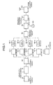
- a transmitter for the multi- cated delay multiplexing direct spread spectrum communication system which is a first embodiment of the present invention is shown in Fig. 6.
- the transmitter illustrated in the drawing corresponds to the prior art shown in Fig. 3.
- a gain-variable amplifier 21 which is disposed at the succeeding stage of the modulator 19 is controlled in response to a control signal which is generated based upon a detection signal which is generated by detecting the output of a power amplifier 23.
- This control is conducted in the detection and control portion 21c. Detection is usually conducted by means of a diode.
- the average power is determined as a voltage by means of an integrator, etc.
- the gain-variable amplifier 21 is controlled in response to a control signal which is generated by comparison between the determined voltage and a reference voltage, so that the output of the gain-variable amplifier 21 is equal to the reference voltage in amplitude.
- the time constant of the integration in the detection and control portion 21c is shortened by a constant period of time.
- the time constant is shortened by a given period of time in response to a control signal representative of a simplex/multiplex part.
- the control signal can use a signal from a multiplexing switching circuit in the transmitter portion, or a upper level layer which controls this circuit. Switching of the time constant can be readily implemented by switching capacitors having different capacitance.
- the constant period of time during which the switching is conducted is determined by experiments, etc. in consideration of the period of time which is taken for stabilization due to shortening of the time constant.
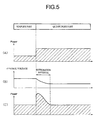
- Fig. 7(A) The changes in the power on the input side of the gain-variable amplifier 21 are shown in Fig. 7(A).
- the changes in the voltage of the control signal when the above-mentioned time constant of the integration is decreased (the integration interval is shortened) are shown in Fig. 7(B).
- the changes in the power of the controlled transmission output are shown in Fig. 7(C).
- the time constant is decreased in response to the control signal and the time constant is increased after the lapse of a predetermined period of time.
- control may be conducted so that the time constant is decreased from the start of reception and the time constant is switched after the lapse of a predetermined period of time since switching of multiplexing.
- the length of the simplex part is comparatively shorter. If the time constant is short, the stability is slightly low, so that more or less fluctuations remain. However, the transmission power can be made so constant that only slight deterioration of performance may occur for a short period of time.
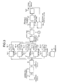
- a transmitter for the multi-rated delay multiplexing direct spread communication system which is a second embodiment of the present invention is shown in Fig. 8.
- the transmitter using the gain-variable amplifier 21 at the succeeding stage of the modulator 19 shown in Fig. 8 is substantially identical in structure with above-mentioned embodiment shown in Fig. 6 except that a control signal which is generated based upon the detected signal obtained by inputting the output of the modulator 19 to the detection and control portion 21c' is subjected to level conversion in a level converting portion 21t and is input to the gain-variable amplifier 21 as a control signal.
- the present embodiment has a feature that the level of the control signal from the detection and control portion 21c' is converted by inputting the control signal for simplex/multiplex part to the level converting portion 21t.
- the amplitude level of the simplex part is different from that of the multiplex part. Since the average of the amplitude is a linear sum, the average of the power is 5 times for quintuplexing.
- the amplitude of the signal after detection is ⁇ 5.
- the present invention has means for correspondingly converting the level of the control voltage output from the detection and control portion 21c' based upon the preliminarily known multiplicity.
- control voltage is changed by a corresponding amount since the amplitude would be
- Fig. 9(A) shows the changes in power on the input side of the gain-variable amplifier 21.
- Fig. 9(B) shows the changes in the control voltage and
- Fig. 9(C) shows the changes in the power of the controlled transmission output.
- a signal before the gain-variable amplifier 21 is used as detection signal.
- the detection power from the multiplex part is 5 times (refer to Fig. 9(A)).
- the gain-variable amplifier 21 is of the type in which amplification factor is increased in proportional to the voltage.
- the analog signals which have been modulated are subjected to processing.
- the signals are D/A converted by a D/A convertor, etc. and input to the modulator.
- level conversion is conducted for the digital signals prior to D/A conversion.
- the present embodiment is relevant to the prior art in Fig. 4 excepting the level conversion.
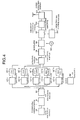
- Level conversion in the form of digital signals is conducted in an operating portion 17 prior to the D/A converting portion 18 in Fig. 10. At this end, a control signal depending upon the multiplicity is input from an external portion to the operating portion 17.
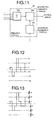
- the circuit configuration of the operating portion 17 is shown in detail in Fig. 11.
- the operating portion 17 comprises an adder 17a for adding for multiplexing the delayed spread signals, a multiplying operating portion 17m for conducting the level conversion and a multiplier generating portion 17i, which receives a control signal having simple/multiplex part for generating a multiplier which is used for the level conversion.
- Figs. 12 and 13 are wave form charts explaining the operating function, showing the wave forms prior to and after the operation of the multiplying operating portion 17m when quintuplexing is conducted, respectively.
- the signals assume six values such as 5, 3, 1, -1, -3, -5 before the multiplying operating portion 17m and assumes six values such as (5/ ⁇ 5)k, (3/ ⁇ 5)k, (1/ ⁇ 5)k, (-1/ ⁇ 5)k, (-3/ ⁇ 5)k, (-5/ ⁇ 5), after the multiplying operating portion 17m.
- the amplitude level conversion is thus conducted.
- the average power of the simplex part is equal to that of the multiplex part.
- k is preset in such a manner that the quantization error of the signal which is given to D/A convertor becomes less.
- the six values assume 2.236, 1.342, 0.447, -0.447, -1.342, -2.236.
- the values assume 2, 1, 0, 0, -1, 2 if the result of operation is operated by counting fractions of 5 and over as a portion and disregarding the rest since the analog value corresponds to a discrete value of an integer in case of D/A conversion. The error on quantization would be come larger, so that equal 6 levels would not occur.
- k is selected about 100, the resolution would become higher, so that the quantization error could be 1/100.
- This k is selected depending upon the number of quantization bits of the D/A convertor. For example, k differs whether the convertor is 8 or 10 bit D/A convertor.
- the transmission output can be constant by subjecting the operation result of the digital portion to an operation. Since the transmission output is not influenced by the time constant of the integrator, etc. by conducting the level conversion in the digital portion as is done in the former embodiment, level conversion can be conducted on a real time basis in response to a control signal, so that the output error at transient can be less.
- a transmitter for the multi-rated delay multiplexing direct spread spectrum communication system which is a fourth embodiment of the present embodiment will be described.
- the quantization error of the D/A convertor is made less by selecting k in the above-mentioned embodiment. However, a slight quantization error remains.
- the residual error can be absorbed by combining the level control of the transmission output in the third embodiment with that in first and second embodiments.
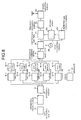
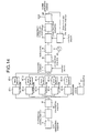
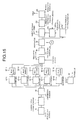
- FIGs. 14 and 15 More detailed configuration of the present embodiment is illustrated in Figs. 14 and 15.
- the transmitter (transmitting device) shown in Fig. 14 is arranged in such a manner that the detection and control portion in the transmitter shown in Fig. 10 is operated in response to a control signal for the simplex/multiplex part (this operation is identical with that of the detection and control portion 21c in Fig. 6).
- the transmitter of Fig. 15 is arranged in such a manner that its detection and control portion is operated by means of the detection and control portion 21c' and the level converting portion 21d shown in Fig. 8.
- the frequency combiner in Figs. 6 and 8 is replaced with an operating portion, which is controlled in response to a control signal.
- the residual quantization error can be absorbed by the effects of the first and second embodiments. This is effective in particular when the number of bits of the D/A convertor is small.
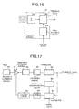
- a transmitter for the multi-rated delay multiplexing direct spread spectrum communication system which is a fifth embodiment of the present invention is shown in Fig. 16. Only an operation portion is shown in Fig. 16. The operating portion is used as the operating portion in the third embodiment (refer to Figs. 10 and 11) and in the fourth embodiment (refer to Figs. 14 and 15).
- the operating portion 17 which is shown in Fig. 16 comprises an adder 17a for adding delayed signals, a table selecting circuit 17s for selecting a table which will be used among the numeral value tables in response to a selecting signal and numeral value tables 17t.
- a multiplier is selected for each multiplying operation.
- the multiplier can be eliminated by preliminarily determining the values after multiplying and stored them in the numeral value table 17t since the multiplicity is several at most.
- the multiplier has generally a large circuit, and a large number of operating bits is necessary to conduct operations relating with ⁇ and a long period of time for the operation is taken.
- the table selecting circuit 17s is operated in response to a control signal to generate a select signal for determining the table of the multiplicity in the table 17t to be selected.
- the numeral number table 17t is accessed depending upon the added value of the adder 17a for obtaining its output.
- the circuit can be made smaller by preliminarily providing a numeral value table which operates in such a manner. Only selection from a table is required so that the speed will become higher.
- a receiver for the multi-rated delay multiplexing direct spread spectrum communication system which is a sixth embodiment of the present invention will be described.
- the problem is reduced by a method of making the reception output constant by a gain-variable amplifier on the receiver side. Since the spectrum spread signal generally has a low C/N which may be sometime negative. AGC may not be normally operated for the signals which have not been correlated.
- the problem is solved by arranging the system in such a manner that the level of the received signal is kept constant in response to the received correlation output in accordance with the present invention when AGC is performed.
- FIG. 17 An embodiment of the present invention having such a configuration is shown in Fig. 17.
- a signal which is received by an antenna is converted into an IF signal by a frequency converting portion 50.
- a gain controlled amplifier 51 which amplifies the converted IF signal is provided so that the amplification can be controlled.
- the other amplifiers and filters are shown as being omitted in Fig. 17.
- the frequency of the signal is converted to provide a base band signal by a frequency converting portion 52 and then digitalized by an A/D converting portion 53. Correlation between the signals is determined by a correlator 54.
- the output of the correlator 54 is used for demodulation and is simultaneously input to a correlation synchronization circuit 55 for extracting the correlation timing.
- a comparator 51s into which the output of the correlator is input is used.
- a control signal for the gain controlled amplifier 51 is generated by passing the output of the comparator 51s through a filter 51f and a control circuit 51c. That is, comparation between the signal and a preset value is conducted by the comparator 51s in correlation spike timing at correlation synchronization timing in a correlation synchronization circuit 55 for controling the gain controlled amplifier 51 by using a value depending upon a comparison result as a control signal so that the correlation output is constant in such a system.
- control signal is generated by feed-backing the correlation output
- the correlation output after controlling is proportional to the received signal component. Since control can be conducted at a higher C/N than that when control is conducted by detecting the spread signal, the control precision can be enhanced.
- the correlation output for the multiplex part would be lowered than that for the simplex part when the signal is received without any conversion.
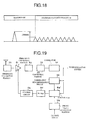
- FIG. 19 A seventh embodiment of the present invention for overcoming this problem is shown in Fig. 19.
- the embodiment show in Fig. 19 is substantially identical with that shown in Fig. 17 excepting that a preset value generating portion 51g in which the present value is changed in response to a control signal is added.
- the present embodiment has a feature that the presetting of the preset value generating portion 51g is changed in response to a control signal representative of the multiplicity for switching the preset value given to the comparator 51s' independently of the multiplex part.
- the present value is switched to 1, ⁇ 2, ⁇ 3, ⁇ 4, ⁇ 5, etc. depending upon the multiplicity.
- the timing of generating this control signal may be changed by determining the switching timing in response to a signal which is demodulated on reception or depending upon the preliminarily determined data length.
- the preset value may be slightly changed depending upon data of experiments or simulations.
- the demodulation power on reception can be kept constant even if multiplicity is switched.
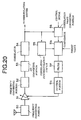
- FIG. 20 An eighth embodiment in which the gain adjustment on the receiver side is performed by an alternative method is shown in Fig. 20.
- the embodiment shown in Fig. 20 is substantially identical with that in Fig. 17 except that a correlation value converting portion 56 which is controlled by a control signal is added to the embodiment shown in Fig. 17 so that the output of the correlation value converting portion 56 is the correlation input value to the comparator 51s.
- the correlation output can be changed.
- the correlation value converting portion 56 is provided.
- the received power can be kept constant even after the switching of multiplexing by operating the correlation value converting portion 56 in response to a control signal for converting the output correlation signal which will be input to the comparator 51s.
- the timing at which this control signal is generated can be similarly obtained.
- the preset value may adjusted slightly based upon data of experiments and simulations.
- demodulated signal power on reception can be kept constant even if multiplexing is switched.
- the transmission signal relying on a delay multiplexing scheme which may be multi-rated is in a format having a non-multiplex (simplex) part and multiplex part which is multiplexed in this scheme
- standard of Japanese Radio Law can be satisfied and load imposed upon the power amplifier can be mitigated by controlling the transmission power so that it is made constant for the simplex/multiplex part of the transmission signal.
- the fluctuation in output at the transient can be suppressed small by reducing the time constant of the integration in the detecting means at the transient on switching of the multiplicity.
- the disadvantage that the transmission output which is generated at the transient on switching of the multiplicity can be reduced. Reduction in the time constant from the beginning of the simplex part can eliminate the control of the time constant on switching the multiplex part following the simplex part.
- the fluctuation in output at the transient can be more quickly suppressed to a small range by changing the level of the control voltage for controlling the gain of the amplifier depending upon the switching of the multiplicity.
- the transmission power can be made constant without changing the analog system by the square root of the average amplitude of non-multiplexed value and multiplexed value, or for each number of the multiplicity. Processing is easy and the influence at the transient is eliminated.
- an amplitude control method using the correlation output can be used for communications signal having a format of simplex/multiplex part by presetting a comparison value which is referenced to a value depending upon the power ratio by a multiplexing switching part or alternatively by operating a value given to AGC into a value depending upon the power ratio from the multiplexing switching portion.
- a communication system which utilizes the advantages of the transmitter and receiver of the present invention is provided.
Landscapes
- Engineering & Computer Science (AREA)
- Computer Networks & Wireless Communication (AREA)
- Signal Processing (AREA)
- Transmitters (AREA)
- Mobile Radio Communication Systems (AREA)
Applications Claiming Priority (3)
| Application Number | Priority Date | Filing Date | Title |
|---|---|---|---|
| JP30218297 | 1997-11-04 | ||
| JP30218297A JP3406494B2 (ja) | 1997-11-04 | 1997-11-04 | マルチレート化遅延多重方式スペクトル直接拡散通信システムにおける送信装置および受信装置並びにマルチレート化遅延多重方式スペクトル直接拡散通信システム |
| PCT/JP1998/004704 WO1999023777A1 (fr) | 1997-11-04 | 1998-10-16 | Emetteur et recepteur pour systeme de communication a plusieurs vitesses a spectre disperse direct par multiplexage du temps de propagation, et systeme precite |
Publications (3)
| Publication Number | Publication Date |
|---|---|
| EP1037422A1 true EP1037422A1 (fr) | 2000-09-20 |
| EP1037422A4 EP1037422A4 (fr) | 2002-03-20 |
| EP1037422B1 EP1037422B1 (fr) | 2004-04-28 |
Family
ID=17905929
Family Applications (1)
| Application Number | Title | Priority Date | Filing Date |
|---|---|---|---|
| EP98947923A Expired - Lifetime EP1037422B1 (fr) | 1997-11-04 | 1998-10-16 | Emetteur et recepteur pour systeme de communication a plusieurs vitesses a spectre disperse direct par multiplexage du temps de propagation, et systeme precite |
Country Status (6)
| Country | Link |
|---|---|
| US (1) | US6738448B1 (fr) |
| EP (1) | EP1037422B1 (fr) |
| JP (1) | JP3406494B2 (fr) |
| AU (1) | AU9463098A (fr) |
| DE (1) | DE69823545T2 (fr) |
| WO (1) | WO1999023777A1 (fr) |
Cited By (2)
| Publication number | Priority date | Publication date | Assignee | Title |
|---|---|---|---|---|
| US6859487B1 (en) * | 1999-03-03 | 2005-02-22 | Nec Corporation | Radio communication system and base station and mobile terminal to be employed therein |
| CN102355720A (zh) * | 2003-08-07 | 2012-02-15 | 松下电器产业株式会社 | 无线发送装置及无线发送方法 |
Families Citing this family (6)
| Publication number | Priority date | Publication date | Assignee | Title |
|---|---|---|---|---|
| JP4162323B2 (ja) | 1999-04-06 | 2008-10-08 | シャープ株式会社 | スペクトル拡散通信用送信機 |
| DE10154547A1 (de) * | 2001-11-07 | 2003-05-15 | Beiersdorf Ag | Dünnflüssige, sprühbare W/O Emulsionen |
| JP2003258768A (ja) | 2002-02-27 | 2003-09-12 | Fujitsu Ltd | 拡散信号多重化回路 |
| CN1833390B (zh) * | 2003-08-07 | 2012-01-18 | 松下电器产业株式会社 | 无线发送装置及无线发送方法 |
| JP2006135617A (ja) * | 2004-11-05 | 2006-05-25 | Matsushita Electric Ind Co Ltd | 受信装置及び自動利得制御方法 |
| JP4097656B2 (ja) | 2005-02-28 | 2008-06-11 | 三洋電機株式会社 | 受信方法および装置 |
Family Cites Families (14)
| Publication number | Priority date | Publication date | Assignee | Title |
|---|---|---|---|---|
| JP2896817B2 (ja) * | 1990-06-14 | 1999-05-31 | クラリオン株式会社 | スペクトラム拡散通信装置 |
| US5291515A (en) * | 1990-06-14 | 1994-03-01 | Clarion Co., Ltd. | Spread spectrum communication device |
| JPH05130068A (ja) * | 1991-10-31 | 1993-05-25 | Icom Inc | 周波数拡散変調装置 |
| AU660357B2 (en) * | 1992-03-23 | 1995-06-22 | Sharp Kabushiki Kaisha | Spread spectrum communication system and an apparatus for communication |
| US5559828A (en) * | 1994-05-16 | 1996-09-24 | Armstrong; John T. | Transmitted reference spread spectrum communication using a single carrier with two mutually orthogonal modulated basis vectors |
| US5602833A (en) * | 1994-12-19 | 1997-02-11 | Qualcomm Incorporated | Method and apparatus for using Walsh shift keying in a spread spectrum communication system |
| JPH08335928A (ja) * | 1995-06-07 | 1996-12-17 | Oki Electric Ind Co Ltd | 受信装置 |
| JP2863993B2 (ja) * | 1995-06-22 | 1999-03-03 | 松下電器産業株式会社 | Cdma無線多重送信装置およびcdma無線多重伝送装置およびcdma無線受信装置およびcdma無線多重送信方法 |
| JP3161943B2 (ja) * | 1995-07-07 | 2001-04-25 | シャープ株式会社 | データ復調方法およびスペクトル拡散通信システム |
| JPH0955714A (ja) | 1995-08-11 | 1997-02-25 | Sharp Corp | スペクトル拡散通信システム |
| JPH09289501A (ja) * | 1996-04-22 | 1997-11-04 | Sharp Corp | スペクトル拡散通信受信機 |
| US5805585A (en) * | 1996-08-22 | 1998-09-08 | At&T Corp. | Method for providing high speed packet data services for a wireless system |
| JPH1093531A (ja) * | 1996-09-18 | 1998-04-10 | Canon Inc | 符号分割多重通信装置 |
| JPH10164014A (ja) * | 1996-11-25 | 1998-06-19 | Sharp Corp | スペクトル拡散通信受信方法 |
-
1997
- 1997-11-04 JP JP30218297A patent/JP3406494B2/ja not_active Expired - Fee Related
-
1998
- 1998-10-16 WO PCT/JP1998/004704 patent/WO1999023777A1/fr not_active Ceased
- 1998-10-16 EP EP98947923A patent/EP1037422B1/fr not_active Expired - Lifetime
- 1998-10-16 US US09/509,486 patent/US6738448B1/en not_active Expired - Lifetime
- 1998-10-16 DE DE1998623545 patent/DE69823545T2/de not_active Expired - Fee Related
- 1998-10-16 AU AU94630/98A patent/AU9463098A/en not_active Abandoned
Non-Patent Citations (2)
| Title |
|---|
| No further relevant documents disclosed * |
| See also references of WO9923777A1 * |
Cited By (2)
| Publication number | Priority date | Publication date | Assignee | Title |
|---|---|---|---|---|
| US6859487B1 (en) * | 1999-03-03 | 2005-02-22 | Nec Corporation | Radio communication system and base station and mobile terminal to be employed therein |
| CN102355720A (zh) * | 2003-08-07 | 2012-02-15 | 松下电器产业株式会社 | 无线发送装置及无线发送方法 |
Also Published As
| Publication number | Publication date |
|---|---|
| AU9463098A (en) | 1999-05-24 |
| WO1999023777A1 (fr) | 1999-05-14 |
| EP1037422A4 (fr) | 2002-03-20 |
| JP3406494B2 (ja) | 2003-05-12 |
| DE69823545T2 (de) | 2005-04-14 |
| EP1037422B1 (fr) | 2004-04-28 |
| JPH11145932A (ja) | 1999-05-28 |
| US6738448B1 (en) | 2004-05-18 |
| DE69823545D1 (de) | 2004-06-03 |
Similar Documents
| Publication | Publication Date | Title |
|---|---|---|
| EP1388937B1 (fr) | Amplificateur radiofréquence comprenant un limiteur adaptatif | |
| CN1042585C (zh) | 自动增益控制装置、通信系统和自动增益控制方法 | |
| US7489907B2 (en) | Transmitter for suppressing a variation in input level of a multicarrier signal | |
| US6920173B2 (en) | Spread-spectrum signal receiver apparatus and interference cancellation apparatus | |
| JP4610697B2 (ja) | 送信電力制御方法及び無線通信装置 | |
| EP1061643B1 (fr) | Récepteur et méthode de commande de gain dudit récepteur | |
| EP1360760B1 (fr) | Limitation d'amplitude | |
| US6965658B1 (en) | Method and means for telecommunication | |
| AU739474B2 (en) | Device and method for measuring non-orthogonal noise power for CDMA communication system | |
| EP1037422B1 (fr) | Emetteur et recepteur pour systeme de communication a plusieurs vitesses a spectre disperse direct par multiplexage du temps de propagation, et systeme precite | |
| JP2000252868A (ja) | Cdma通信装置とその自動利得制御回路 | |
| EP1011207B1 (fr) | Contrôle de la puissance de transmission d'une signal en bande de base en fonction du nombre de codes de transmission | |
| AU2003272130A1 (en) | Apparatus and method for compensating gain of an automatic gain controller | |
| JP3695732B2 (ja) | Cdma受信装置のサーチ装置 | |
| KR19980080649A (ko) | 무선 송신 장치 및 무선 송신 장치의 이득 제어 방법 | |
| US7251463B2 (en) | Methods and apparatus for controlling signals | |
| US20100022212A1 (en) | Radio Receiver | |
| US8275339B2 (en) | Fixed point FIR filter with adaptive truncation and clipping and wireless mobile station using same | |
| US5832023A (en) | Spread spectrum receiver using absolute-value determination for code tracking | |
| US20110274223A1 (en) | Agc tuner for mimo systems | |
| US20030219079A1 (en) | Data transmission method and arrangement | |
| US7577183B2 (en) | Transmission apparatus and peak reduction method | |
| JPH08307287A (ja) | 無線通信装置 | |
| KR20090060841A (ko) | 이동국의 자동 수신 이득 제어 방법 및 장치 | |
| EP1266460B1 (fr) | Methodes, systemes et dispositifs permettant de pre-compenser des interferences entre des signaux codes transmis |
Legal Events
| Date | Code | Title | Description |
|---|---|---|---|
| PUAI | Public reference made under article 153(3) epc to a published international application that has entered the european phase |
Free format text: ORIGINAL CODE: 0009012 |
|
| 17P | Request for examination filed |
Effective date: 20000425 |
|
| AK | Designated contracting states |
Kind code of ref document: A1 Designated state(s): DE FR GB |
|
| A4 | Supplementary search report drawn up and despatched |
Effective date: 20020205 |
|
| AK | Designated contracting states |
Kind code of ref document: A4 Designated state(s): DE FR GB |
|
| RIC1 | Information provided on ipc code assigned before grant |
Free format text: 7H 04J 13/00 A, 7H 04B 7/005 B |
|
| GRAP | Despatch of communication of intention to grant a patent |
Free format text: ORIGINAL CODE: EPIDOSNIGR1 |
|
| GRAS | Grant fee paid |
Free format text: ORIGINAL CODE: EPIDOSNIGR3 |
|
| GRAA | (expected) grant |
Free format text: ORIGINAL CODE: 0009210 |
|
| AK | Designated contracting states |
Kind code of ref document: B1 Designated state(s): DE FR GB |
|
| REG | Reference to a national code |
Ref country code: GB Ref legal event code: FG4D |
|
| REF | Corresponds to: |
Ref document number: 69823545 Country of ref document: DE Date of ref document: 20040603 Kind code of ref document: P |
|
| ET | Fr: translation filed | ||
| PLBE | No opposition filed within time limit |
Free format text: ORIGINAL CODE: 0009261 |
|
| STAA | Information on the status of an ep patent application or granted ep patent |
Free format text: STATUS: NO OPPOSITION FILED WITHIN TIME LIMIT |
|
| 26N | No opposition filed |
Effective date: 20050131 |
|
| PGFP | Annual fee paid to national office [announced via postgrant information from national office to epo] |
Ref country code: DE Payment date: 20071011 Year of fee payment: 10 |
|
| PGFP | Annual fee paid to national office [announced via postgrant information from national office to epo] |
Ref country code: GB Payment date: 20071010 Year of fee payment: 10 Ref country code: FR Payment date: 20071009 Year of fee payment: 10 |
|
| GBPC | Gb: european patent ceased through non-payment of renewal fee |
Effective date: 20081016 |
|
| REG | Reference to a national code |
Ref country code: FR Ref legal event code: ST Effective date: 20090630 |
|
| PG25 | Lapsed in a contracting state [announced via postgrant information from national office to epo] |
Ref country code: DE Free format text: LAPSE BECAUSE OF NON-PAYMENT OF DUE FEES Effective date: 20090501 |
|
| PG25 | Lapsed in a contracting state [announced via postgrant information from national office to epo] |
Ref country code: FR Free format text: LAPSE BECAUSE OF NON-PAYMENT OF DUE FEES Effective date: 20081031 |
|
| PG25 | Lapsed in a contracting state [announced via postgrant information from national office to epo] |
Ref country code: GB Free format text: LAPSE BECAUSE OF NON-PAYMENT OF DUE FEES Effective date: 20081016 |