EP1103447A2 - Construction de toit pour véhicule avec panneau de toit en résine thermoplastique - Google Patents
Construction de toit pour véhicule avec panneau de toit en résine thermoplastique Download PDFInfo
- Publication number
- EP1103447A2 EP1103447A2 EP00310397A EP00310397A EP1103447A2 EP 1103447 A2 EP1103447 A2 EP 1103447A2 EP 00310397 A EP00310397 A EP 00310397A EP 00310397 A EP00310397 A EP 00310397A EP 1103447 A2 EP1103447 A2 EP 1103447A2
- Authority
- EP
- European Patent Office
- Prior art keywords
- roof
- roof panel
- extension
- retainer
- roof construction
- Prior art date
- Legal status (The legal status is an assumption and is not a legal conclusion. Google has not performed a legal analysis and makes no representation as to the accuracy of the status listed.)
- Granted
Links
Images




Classifications
-
- B—PERFORMING OPERATIONS; TRANSPORTING
- B62—LAND VEHICLES FOR TRAVELLING OTHERWISE THAN ON RAILS
- B62D—MOTOR VEHICLES; TRAILERS
- B62D29/00—Superstructures, understructures, or sub-units thereof, characterised by the material thereof
- B62D29/04—Superstructures, understructures, or sub-units thereof, characterised by the material thereof predominantly of synthetic material
- B62D29/048—Connections therefor, e.g. joints
-
- B—PERFORMING OPERATIONS; TRANSPORTING
- B62—LAND VEHICLES FOR TRAVELLING OTHERWISE THAN ON RAILS
- B62D—MOTOR VEHICLES; TRAILERS
- B62D25/00—Superstructure or monocoque structure sub-units; Parts or details thereof not otherwise provided for
- B62D25/06—Fixed roofs
Definitions
- the present invention relates to a roof construction for a vehicle, and more particularly to a roof construction having a plastics roof panel.
- Thermoplastic roof panel is herein used to mean a roof panel of synthetic resin or a roof panel of thermoplastic resin.
- JP- 61-117774 (Utility Model) discloses a resin roof panel.
- an inner side of a resin roof panel has ribs connected to a roof section of a body frame structure by pins.
- the construction is not satisfactory in eliminating appearance of residual deformation at ends of the ribs or inward displacement at edges of the resin roof panel upon deformation of the roof panel due to a great drop in environmental temperature.
- a roof construction for a vehicle comprising: a body frame structure; a resin roof panel including a major portion with bounds, extensions hanging down from said bounds of said major portion, and attachment flanges connected to lower portions of said extensions, respectively; a connector connecting at least one of said attachment flanges to one of said body frame structure; and a stopper suppressing inward displacements of said roof panel from an outer periphery thereof upon deformation of said roof panel due to a change in environmental temperature.
- a roof construction for a vehicle comprising; a thermoplastic resin roof panel including a major portion with bounds, extensions hanging down from said bounds of said major portion, and attachment flanges connected to lower portions of said extensions, respectively; a metal body frame structure including a roof section with support flanges underlying said attachment flanges, respectively, said attachment flanges being formed with a plurality of holes; a connector extending through at least one said holes and connecting at least one of said attachment flanges to one of said support flanges, said extensions being so constructed and arranged as to move in directions allowing inward displacements of said major portion upon deformation of said major portion due to a change in environmental temperature; and means for suppressing displacements of said attachment flanges relative to said support flanges and said connector upon movements of said extensions in directions allowing inward displacements of said major portion.
- Figure 1 is a perspective view of a motor vehicle embodying the present invention
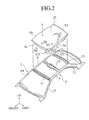
- Figure 2 is an exploded view of a plastic roof panel 5 and a metal body frame structure
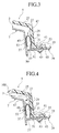
- Figure 3 is a cross-section taken though the line S3-S3 in Figure 1
- Figure 5 is an enlarged view of a portion surrounded by a circle C5 in Figure 1
- Figure 6 is a cross-section taken though the line S6-S6 in Figure 1.
- a metal body frame structure 1 includes, as a structural part, a roof section 3.
- Metal body frame structure 1 may be made of, for example, steel or aluminum alloy or magnesium alloy.
- Roof section 3 includes a left side rail 7, a right side rail 9, a front roof rail 11, a rear roof rail 13, and a bow roof 15.
- Roof section 3 also includes a left front pillar 17, a right front pillar 19, a left rear pillar 21,and a right rear pillar 23.
- Side roof rails 7 and 9 extend from left and right end portions of front roof rail 11 to left and right end portions of rear roof rail 13, respectively.
- Body structure 1 also includes other components, such as, for example, an engine compartment, a luggage compartment,and a platform.
- Roof panel 5 is made of thermoplastic resin. At its left, right, front,and rear peripheries 5a, 5b, 5c,and 5d, roof panel 5 is firmly connected to left, right, front, and rear roof rails 7, 9, 11, and 13. Left, right, front, and rear peripheries 5a, 5b, 5c,and 5d extend along left, right, front,and rear roof rails 7, 9, 11, and 13, respectively.
- roof panel 5 has a major portion 25 defining an upper roof contour of the motor vehicle.
- Major portion 25 has bounds 27 that are disposed inwardly from the outer periphery of the vehicle body.
- Roof panel 5 has two laterally spaced attachment flanges, only one being shown at 35, and two longitudinally spaced front and rear attachment flanges, only front one being shown at 35A, which extend along bounds 27, respectively.
- roof panel 5 includes two lateral extensions, only one being shown at 29, and two front and rear extensions, one front extension being shown at 29A.
- extension 29 is connected to the major portion 25 at angles to form a corner at bound 27.
- extension 29 is connected to the corresponding attachment flange 35 at angles to form a corner at a junction 31 between extension 29 and attachment flange 35.
- extension 29A is connected to major portion 25 at angles to form a corner at bound 27.
- extension 29A is connected to attachment flange 35A at angles to form a corner at a junction 31A between extension 29A and attachment flange 35A.
- Thermoplastic roof panel 5 is an integral piece formed by, for example, injection molding.
- Side roof rails 7 and 9 are in mirror image relationship in structure with respect to the fore and aft direction of the motor vehicle. Accordingly, the following explanation as to and in association with side roof rail 7 is applicable in understanding side roof rail 9 and its relationship with roof panel 5.
- side roof rail 7 has a longitudinally extending wall 37 disposed inboard and in spaced relationship with respect to extension 29 hanging down from the major portion 25.
- Side roof rail 7 has a support flange 39.
- Support flange 39 extends from wall 37 and underlies attachment flange 35.
- Wall 37 and extension 29 define therebetween a space 50 and support flange 39 closes lower side, viewing in Figure 3, of space 50.
- Front and rear roof rails 11 and 13 offer substantially the same relationship with roof panel. Accordingly, the following explanation as to and in association with front roof rail 11 is applicable in understanding rear roof rail 13 and its relationship with roof panel 5.
- front roof rail 11 has a transversely extending wall 37A disposed inboard and in spaced relationship with respect to extension 29A hanging down from the major portion 25.
- Front roof rail 11 also has a support flange 39A.
- Support flange 39A extends from wall 37A and underlies attachment flange 35A.
- Wall 37A and extension 29A define therebetween a space 50A and support flange 39A closes lower side, viewing in Figure 3, of space 50A.
- the attachment flanges for example, 35 and 35A are connected to the corresponding support flanges 39, respectively, by fasteners (or connectors), each in the form of a bolt 41 and a nut 43 in this embodiment (see Figures 3 and 6).
- fasteners or connectors
- bolts 41 and nuts 43 rivets may be used.
- an adhesive may be used in the place of or in cooperation with such fasteners (or connectors).
- each of attachment flanges 35 and 35A is formed with holes 33 in which bars of the bolts 41 are disposed, respectively.
- the setting is such that annular spaces 45 prevent or at least alleviate damage,on the edges of holes 33, which might be imparted by the bars of bolts 41 during thermal displacement of roof panel 5.
- Such holes 33 may be replaced by cutouts cut inwardly from the periphery of each of the attachment flanges 35 and 35A.
- retainers (or stoppers) 47 are provided for each of laterally spaced attachment flanges 35 and four retainers 47A are provided for each of longitudinally spaced attachment flanges 35A.
- each retainer 47 is formed from a strip of spring steel.
- Retainer (or stopper) 47 has a flat seat or base section 51 and a C-shaped section 49 extending from the seat section 51 into space 50.
- the seat section 51 is interposed between attachment flange 35 and support flange 39 and held therebetween by tightening bolt 41.
- C-shaped section 49 has(and thus may be divided into)an outboard bow 55 connected via a junction 57 to and extending upwardly from seat section 51 and an inboard bow 53.
- Inboard bow 53 extends downwards from outboard bow 55 to form C-shaped section 49.
- each retainer 47 along the longitudinal direction of each of longitudinally extending wall 37 may be appropriately determined.
- C-shaped section 49 offers the common elastic modulus throughout its width.
- Retainers 47A are slightly different in dimension from retainers 47. However, both retainers 47 and 47A offer the same function.
- each retainer 47A is formed from a strip of spring steel.
- Retainer 47A is substantially the same as retainer 47 and has a flat seat or base section 51A and a C-shaped section 49A extending from the seat section 51A into space 50A.
- the seat section 51A is interposed between attachment flange 35A and support flange 39A and held therebetween by tightening bolt 41.
- C-shaped section 49A has(and thus may be divided into) an outboard bow 55A connected via a junction 57 to and extending upwardly from seat section 51A and an inboard bow 53A.
- Inboard bow 53A extends downwards from outboard bow 55A to form C-shaped section 49A.
- Inboard bow 53A bears against longitudinally extending wall 37A and outboard bow 55A bears against extension 29A at a lower portion near attachment flange 35A to hold attachment flange 35A in the illustrated position in Figure 6.
- Figure 5 is a magnified view of a portion surrounded by a circle S6 in Figure 1 or 2. At this portion, extension 29 meets extension 29A. Viewing in Figure 5, retainer 47 on the righthand side is the same, in structure, as that shown in Figure 3, while retainer 47A is the same, in structure, as that shown in Figure 6.
- support flange 39A which is formed near the front edge of front roof rail 11, is connected to laterally extending wall 37A. Laterally extending wall 37A is elevated from the level of support flange 39A less than longitudinally extending wall 37 is elevated from the level of support flange 39.
- a front windshield 63 is connected via adhesive 61 to the support flange 39A at its front edge.
- extension 29A is elevated from the level of attachment flange 35A less than extension 29 is elevated from the level of attachment flange 35.
- retainer 47A its C-shaped section 49A extends from the level of seat section 51A less than C-shaped section 49 of retainer 47 extends from the level of seat section 51 (see Figure 3).
- thermoplastic roof panel 5 under thermal stress at a considerable drop in environmental temperature.
- thermal stress causes displacement in a direction normal to the plane of major portion 25, a change in angle at bound 27, and inward displacement of attachment flanges 35 and 35A relative to support flanges 39 and 39A.
- the amount of such inward displacement of attachment flanges 35 and 35A is not negligible within area where structural rigidity is locally increased and at front and rear peripheries 5a and 5d.
- Structural rigidity of roof panel 5 is increased at a corner 59 where extensions 29 and 29A meet as shown in Figure 5.
- extension 29 and retainer 47 expressly makes great contribution toward elimination of occurrence of residual deformation within thermoplastic roof panel 5.
- the two-dot chain line illustrates the position which extension 29 of roof panel 5 will take under thermal stress at a considerable drop in environmental temperature.
- extension 29 expressly deviates from the original position in an inward direction as indicated by an arrow 100. Upon disappearance of such thermal stress, extension 29 is brought back to the original position. Extension 29 is so constructed and arranged as to expressly deviate from the original position, serving as a mechanism to allow deformation of roof panel 5.
- extension 29 tends to pull or move attachment flange 35 inwardly in a leftward direction viewing in Figure 4, tending to compress C-shaped section 49 of retainer 47.
- Reaction forces in directions as indicated by arrows F created due to compression of C-shaped section 49 minimize the tendency to move attachment flange 35 inwardly. Accordingly, deviation of attachment flange 35 from the original position is prevented or at least minimized by the action of retainer 47 in this first preferred embodiment.
- C-shaped section 49 of retainer 47 pushes attachment flange 35 back to the original position.
- support flange 39 guides and facilitate this return movement of attachment flange 35, assuring high reappearance of the original contour of roof panel 5 upon disappearance of thermal stress.
- attachment flange 35 can maintain annular space 45, thus minimizing the probability that the edge of hole 33 might strike the bar of bolt 41.
- attachment flange 35 will not be cracked around hole 33. Because the relative position of attachment flange 35 to support flange 39 is held, major portion 25 is always reinstated, in its contour, upon disappearance of thermal stress without any residual deformation.
- attachment flange 35 Upon completion of reinstatement of roof panel 5, the shrinkage of attachment flange 35 disappears so that the loose engagement between the head of bolt 41 and nut 43 disappears. Hence, attachment flange 35 is firmly held at the original position.
- retainers 47 and 47A With the provision of retainers 47 and 47A, it has become easy to position roof panel 5 relative to roof portion 3 due to reaction forces imparted by C-shaped sections 49 and 49A of retainers 35 and 35A to walls 37, 37A and extensions 29, 29A. Roof panel 5 is held in the appropriate position relative to roof portion 3 in a stable manner, thus making it quite easy to conduct work by tightening bolts 41 with nuts 43. It is appreciated that, in this case, retainers 47 and 47A support extensions 29, 29A for positioning roof panel 5 relative to roof portion 3. If desired, C-shaped sections 49 and 49A may support extensions 29 and 29A relative to walls 37 and 37A to bias extensions 29 and 29A outwardly only when major portion 25 of roof panel 5 suffers from thermal deformation due to a drop in temperature.
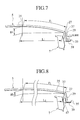
- roof camber is used herein to mean the curvature of a section taken through the central area portion of roof panel major portion 25 relative to its chord. Roof camber is expressed as the ratio of the height of the curved line between one edge and a point within the central area portion to the length of a line section between the one edge and a point vertically below the point within central area portion of a straight line between the one and opposite edges.
- major portion 25 of roof panel 5 has first and second curvatures at two different sections.
- the radius of the first curvature is less than that of the second curvature.
- the first section results from cutting roof panel along a transverse line SD between a middle point on a longitudinal line passing through the central area portion of major portion 25 and a first point on bound 27.
- the second section results from cutting roof panel 5 along an oblique line SC between the middle point on the longitudinal line and a second point on bound 27 near corner 59 (see Figure 5).
- Figure 7 illustrates the first section.
- 11 is the length of the first curvature from the first point on bound 27 to the middle point on the longitudinal line
- L1 is the length of a line section between the first point on bound 27 and a point vertically below the middle point on the longitudinal line
- H1 is the height of the first curvature.
- the roof camber is expressed as H1/L1.
- Figure 8 illustrates the second section.
- 12 is the length of the second curvature from the second point on bound 27 to the middle point on the longitudinal line
- L2 is the length of a line section between the second point on the bound 27 and the point vertically below the middle point on the longitudinal line
- H2 is the height of the second curvature.
- the roof camber is expressed as H2/L2.
- the allowable shrinkage ⁇ is the maximum amount of shrinkage that may be absorbed by deformation in a direction to decrease roof camber.
- the first and second sections has different allowable shrinkages ⁇ 1 and ⁇ 2, which can be expressed as follows:
- the roof camber of each section determines the allowable shrinkage. The greater the roof camber is, the greater the allowable shrinkage is.
- the roof camber for the first section is greater than the roof camber for the second section. Thus, ⁇ 1 is greater than ⁇ 2.
- the length of bound 27 lying in parallel to each of side, front, and rear peripheries 5a, 5b, 5c, and 5d was 1200 mm.
- the height H1 was 50 mm
- the length L1 was 500 mm
- the length 11 was 503.1 mm.
- the height H2 was 50 mm
- the length L2 was 780 mm
- the length 12 was 781.79 mm.
- the displacement of attachment flange 35 can be expressed as the deviation ⁇ 1 of the shrinkage D1 from the allowable shrinkage ⁇ 1.
- the displacement of attachment flange 35 can be expressed as the deviation ⁇ 2 of the shrinkage D2 from the allowable shrinkage ⁇ 2.
- roof retainer 47 is disposed between the lower portion of extension 29 of roof panel 5 and wall 37 of roof section 3 to suppress the displacement of attachment flange 35.
- the conducted simulation may be readily understood from the following Table:
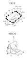
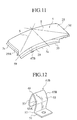
- Figure 11 shows a left half of roof panel 5 as divided by a longitudinal centerline that passes through a central point, i.e., a point within the central area of major portion 25.
- Figure 12 is a perspective view of a retainer 47B used in this example.
- This third embodiment is substantially the same as the first preferred embodiment except spring characteristic imparted to retainer 47B.
- a transverse line between the central point of major portion 25 and a point on the bound of major portion 25 near left periphery 5a of roof panel 5 represents an area where roof camber is relatively great
- a diagonal line S between the central point and a point on front corner 59 of major portion 25 and another diagonal line S between the central point and a point on rear corner of major portion 25 represent areas where roof cambers are relatively low. Allowable shrinkage within area represented by each of diagonal lines S is less than allowable shrinkage within area represented by the transverse line.
- the inward displacement of attachment flange 35 within area represented by diagonal line S is greater than the inward displacement thereof within area represented by the transverse line.
- retainer 47B possesses two different settings for spring characteristic to support the lower portion of attachment flange 35 against different magnitudes of force tending to move attachment flange 35 inwardly.
- C-shaped section 49 may be dividable into (and have) a first half 65A extending inwardly from the side edge near diagonal line S and a second half 65B extending inwardly from the side edge near the transverse line.
- First and second halves 65A and 65B meet with each other at a midpoint between the two side edges.
- the two different settings for spring characteristic are such that the first half 65A provides greater reaction (hard spring setting) than the second half 65 does (less hard spring setting).
- retainer 47B can effectively suppress displacement of attachment flange 35 against two different forces, one along the transverse line, the other along the diagonal line S, acting on wall 29 (or 29A) during shrinkage of roof panel 5.
- first half 65A with hard spring setting extends along the left edge of retainer 47B
- second half 65B with less hard spring setting extends along the right side edge.
- the present invention is intended to encompass a mirror image version of retainer 47B.
- the mirror image version retainer has a first half, with hard spring setting, extending along the right side edge of the retainer, and a second half, with less hard spring setting, extending along the right side edge.
- one retainer 47B of the kind shown in Figure 12 is disposed to support the lower portion of extension 29 at a point between corner 59 and the point through which the transverse line passes.
- Four of such retainers and four of mirror image retainers may be provided, each supporting the lower portion of extension 29 (or 29A) at a point between one of the four corners of major portion 25 and a point through which the transverse line (or the longitudinal centerline) passes. It will be appreciated as an advantage of the second preferred embodiment that, with reduced number of retainers, the lower portion of extension 29 can be supported to suppress inward displacement of attachment flange 35.
- Figures 13 and 14 show modifications of retainer 47B.
- a modified retainer 47C shown in Figure 13 is substantially the same as retainer 47B but the provision of a bead 67.
- Bead 67 is disposed between the left side edge of retainer 47C and a midpoint between the left and right side edges to provide the required spring setting for first half 65A.
- first half 65A with bead 67 can provide greater reaction (hard spring setting) than second half 65B does (less hard spring setting).
- FIG. 14 Another modified retainer 47D shown in Figure 14 is substantially the same as retainer 47B but the provision of a slit 69.
- Slit 69 is disposed between the right side edge of retainer 47D and a midpoint between the left and right side edges to provide the required spring setting for second half 65B.
- second half 65B with bead 69 can provide less great reaction (less hard spring setting) than first half 65A does (hard spring setting).
- bead 67 or slit 69 is a simple and easy measure to provide different spring settings required by first and second halves 65A and 65B in the version as shown in Figure 13 or 14 as well as in its mirror version. If desired, it is also possible to provide such a bead 67 for hard spring setting required by first half 65A and to provide such a slit 69 for less hard setting required by second half 65B.
- the third preferred embodiment is substantially the same as the first preferred embodiment. But, the former is different from the latter in the manner of suppressing displacement of attachment flange 35.
- retainers 47 are used to oppose the tendency of attachment flange 35 to displace, which tendency is caused by transmission of stress by extension 29 during shrinkage of major portion 25.
- extension 29 is formed with a fold 71 along a line dividing an upper portion 29a from a lower portion 29b.
- the upper portion 29a is connected to a major portion 25 of a rood panel 5 at its bound 27.
- the lower portion 29b is connected to an attachment flange 35 to form a junction 31.
- ribs 73 extend from lower portion 28b to attachment flange 35 to firmly hold the angled relationship between lower portion 29b and attachment flange 35. If this relationship can be held, the provision of such ribs is not required.
- This tilting movement of upper portion 28a about fold 71 effectively prevents or at least reduces transmission of stress to lower portion 29b, thus preventing or at least reducing occurrence of displacement of attachment flange 35. Accordingly, it is no longer required to rely mainly on retainers 47 to prevent or at least suppress displacement of attachment flange 35.
- Figure 17 is a perspective view of a retainer 47E.
- the two-dot chain line shows the position of retainer 47E upon shrinkage of roof panel 5 at low temperature.
- the two-dot chain line shows the position of retainer 47E upon expansion of roof panel 5 at high temperature.
- the fully drawn line shows the position of retainer 47E at normal temperature.
- the fourth preferred embodiment is substantially the same as the first preferred embodiment except the use of retainer 47E instead of retainer 47.
- retainer 47E is formed from a strip of a clad metal, which is a lower metal layer 75 in the form of, in this example, steel, overlaid on its upper side with an upper different metal layer 77 in the form of, in this example, aluminum alloy.
- the setting is such that the linear expansion coefficient of lower metal layer 75 is smaller than that of upper metal layer 77.
- the upper metal layer 77 defines an outer side of C-shaped section 49 and an upper side of seat section 51.
- junction 57 changes, in shape, in a direction to decrease an angle between outboard bow 55 and seat section 51, thus inclining C-shaped section 49 toward seat section 51, biasing a lower portion of extension 29 outwardly.
- the lower portion of extension 29 is firmly supported to hold extension 29 against tendency of attachment flange 35 to displace inwardly.
- C-shaped section 49 is at an upright and least expanded position as illustrated in Figure 18 or 19 and free from the above-mentioned inclined or expanded position, making assembly of roof panel 5, retainers 47E,and roof section 3 easy.
- wall 37 supports a lower portion of extension 29.
- Wall 37 has an abutting portion 79 and an escape portion 81.
- Abutting portion 79 is arranged in the proximity of or in contact with a lower portion of extension 29.
- Escape portion 81 is disposed upwardly of abutting portion 79 to define a clearance space for allowing displacement of extension 29.
- abutting portion 79 and escape portion 81 cooperate with each other to define a curved stress control wall section 83.
- extension 29 has a bulge 85 extending from attachment flange 35 toward wall section 83. With the provision of bulge 85, an upper portion of extension 29 extends upwardly.
- Shrinkage of major portion 25 at low temperature causes bulge 85 to come into contact with abutting portion 79 on wall 37.
- the upper portion of extension is deformed within the clearance space defined by escape portion 81 as shown by the two-dot chain line for allowing inward displacement.
- the thermal stress is absorbed by downward displacement of major portion 25 and the displacement of the upper portion of extension 29. If the thermal stress remains, it is absorbed by angle change at bound 27 and spreading of stress over the whole plane of major portion 25.
- the transmission of the displacement of extension 29 to attachment flange 35 is suppressed by abutting portion 79 supporting bulge 85. Accordingly, displacement of attachment flange 35 is suppressed.
Landscapes
- Engineering & Computer Science (AREA)
- Chemical & Material Sciences (AREA)
- Combustion & Propulsion (AREA)
- Transportation (AREA)
- Mechanical Engineering (AREA)
- Architecture (AREA)
- Structural Engineering (AREA)
- Connection Of Plates (AREA)
- Body Structure For Vehicles (AREA)
- Vehicle Interior And Exterior Ornaments, Soundproofing, And Insulation (AREA)
Applications Claiming Priority (2)
| Application Number | Priority Date | Filing Date | Title |
|---|---|---|---|
| JP33339399A JP3436215B2 (ja) | 1999-11-24 | 1999-11-24 | 樹脂ルーフ取付構造 |
| JP33339399 | 1999-11-24 |
Publications (3)
| Publication Number | Publication Date |
|---|---|
| EP1103447A2 true EP1103447A2 (fr) | 2001-05-30 |
| EP1103447A3 EP1103447A3 (fr) | 2001-09-26 |
| EP1103447B1 EP1103447B1 (fr) | 2003-01-22 |
Family
ID=18265628
Family Applications (1)
| Application Number | Title | Priority Date | Filing Date |
|---|---|---|---|
| EP00310397A Expired - Lifetime EP1103447B1 (fr) | 1999-11-24 | 2000-11-23 | Construction de toit pour véhicule avec panneau de toit en plastique |
Country Status (4)
| Country | Link |
|---|---|
| US (1) | US6347829B1 (fr) |
| EP (1) | EP1103447B1 (fr) |
| JP (1) | JP3436215B2 (fr) |
| DE (1) | DE60001256T2 (fr) |
Cited By (2)
| Publication number | Priority date | Publication date | Assignee | Title |
|---|---|---|---|---|
| US6347829B1 (en) * | 1999-11-24 | 2002-02-19 | Nissan Motor Co., Ltd. | Roof construction for vehicle using thermoplastic resin roof panel |
| CN103282264A (zh) * | 2011-01-12 | 2013-09-04 | 丰田自动车株式会社 | 车辆用面板结构 |
Families Citing this family (22)
| Publication number | Priority date | Publication date | Assignee | Title |
|---|---|---|---|---|
| DE10022915A1 (de) * | 2000-05-11 | 2001-11-22 | Webasto Vehicle Sys Int Gmbh | Fahrzeugdach mit einklebbarem Dachmodul |
| US6502895B2 (en) * | 2001-02-23 | 2003-01-07 | International Truck Intellectual Property Company, L.L.C. | Unitized bus vehicle roof |
| AU2002253184A1 (en) * | 2002-04-05 | 2003-10-20 | Grupo Antolin-Ingenieria, S.A. | Car roof module |
| US6918169B2 (en) | 2002-05-14 | 2005-07-19 | Mathson Industries | Method of assembling a vehicle |
| DE10233280B4 (de) * | 2002-07-23 | 2005-09-01 | Arvinmeritor Gmbh | Fahrzeugdachmodul |
| US7032958B2 (en) * | 2003-07-01 | 2006-04-25 | General Motors Corporation | Body and frame assembly for a vehicle and method of assembling a vehicle |
| ATE386676T1 (de) * | 2005-03-18 | 2008-03-15 | Arvinmeritor Gmbh | Karosserieanbauteil, zwischenprodukt und verfahren zum herstellen eines solchen karosserieanbauteils |
| JP4442548B2 (ja) * | 2005-11-09 | 2010-03-31 | トヨタ自動車株式会社 | ルーフヘッダ構造 |
| US7604286B2 (en) * | 2006-01-13 | 2009-10-20 | Nissan Motor Co., Ltd. | Roof structure of a vehicular body |
| US7686385B2 (en) * | 2006-02-02 | 2010-03-30 | U-Haul International, Inc. | Flexible truck skirt with floating mount |
| JP5119887B2 (ja) * | 2007-11-22 | 2013-01-16 | 日産自動車株式会社 | 自動車のルーフ構造 |
| JP5056456B2 (ja) * | 2008-02-15 | 2012-10-24 | 日産自動車株式会社 | サンルーフ取付構造 |
| US20100090500A1 (en) * | 2008-10-13 | 2010-04-15 | Cnh America Llc | Elements of the body of a Vehicle |
| US9085327B2 (en) * | 2009-06-10 | 2015-07-21 | Ford Global Technologies, Llc | Vehicle roof reinforcement |
| KR101382832B1 (ko) * | 2012-08-29 | 2014-04-08 | (주)베바스토동희 홀딩스 | 루프프레임의 하이브리드 결합구조 |
| KR101500353B1 (ko) * | 2012-12-11 | 2015-03-09 | 현대자동차 주식회사 | 복합 차체 패널과 그 제조방법 및 이를 이용한 차체 구조 |
| US8820824B1 (en) * | 2013-03-14 | 2014-09-02 | Honda Motor Co., Ltd. | Vehicle roof structure |
| US9114836B1 (en) | 2014-02-06 | 2015-08-25 | Honda Motor Co., Ltd. | Vehicle roof structure |
| JP6036924B2 (ja) * | 2015-06-03 | 2016-11-30 | トヨタ自動車株式会社 | 樹脂製パネルの接合構造 |
| JP6595521B2 (ja) * | 2017-02-08 | 2019-10-23 | トヨタ自動車株式会社 | 車体上部構造 |
| KR102371249B1 (ko) * | 2017-07-20 | 2022-03-04 | 현대자동차 주식회사 | 차체의 결합구조 |
| RU191252U1 (ru) * | 2019-04-03 | 2019-07-31 | Акционерное общество "АвтоВАЗ" | Верхняя часть автомобиля |
Citations (1)
| Publication number | Priority date | Publication date | Assignee | Title |
|---|---|---|---|---|
| JPS61117774U (fr) | 1985-01-10 | 1986-07-25 |
Family Cites Families (29)
| Publication number | Priority date | Publication date | Assignee | Title |
|---|---|---|---|---|
| JPS5882991U (ja) * | 1981-11-30 | 1983-06-04 | 日産自動車株式会社 | 樹脂パネル取付け構造 |
| JPS58110238A (ja) | 1981-12-24 | 1983-06-30 | 利部 靖彦 | 発泡体の表面コ−テイング |
| JPS58110380A (ja) * | 1981-12-25 | 1983-06-30 | Nissan Motor Co Ltd | 自動車のル−フ構造 |
| US4573733A (en) * | 1982-11-19 | 1986-03-04 | General Motors Corporation | Apparatus for mounting plastic body panel |
| JPS6036376U (ja) * | 1983-08-22 | 1985-03-13 | 三菱自動車工業株式会社 | 車体の複合構造 |
| US4610478A (en) * | 1984-03-01 | 1986-09-09 | General Motors Corporation | Fiberglass headliner with integral roof bows and roof rails |
| JPS6111774A (ja) | 1984-06-27 | 1986-01-20 | Fuji Xerox Co Ltd | 定着装置 |
| JPS61117774A (ja) | 1984-11-13 | 1986-06-05 | Matsushita Electric Ind Co Ltd | 磁気記録再生装置 |
| US4600621A (en) * | 1984-12-28 | 1986-07-15 | Monsanto Company | Thermoformable polymeric foam headliners |
| JPH0137339Y2 (fr) * | 1985-01-10 | 1989-11-10 | ||
| JPH0123891Y2 (fr) * | 1985-01-10 | 1989-07-20 | ||
| JPS6267876U (fr) * | 1985-10-21 | 1987-04-27 | ||
| JPS6278577U (fr) * | 1985-11-06 | 1987-05-20 | ||
| JPS62194980A (ja) | 1986-02-19 | 1987-08-27 | Mazda Motor Corp | 自動車用プラスチツクル−フの取付構造 |
| JPH0632451Y2 (ja) * | 1987-05-20 | 1994-08-24 | 三菱自動車工業株式会社 | 車体構造 |
| JPS642648U (fr) * | 1987-06-26 | 1989-01-09 | ||
| FR2619535B1 (fr) * | 1987-08-20 | 1994-06-17 | Webasto Ag Fahrzeugtechnik | Toit de vehicule avec une ouverture de toit |
| US5120593A (en) * | 1988-05-09 | 1992-06-09 | Honda Giken Kogyo Kabushiki Kaisha | Vehicular roof structure |
| JPH085407B2 (ja) | 1988-10-26 | 1996-01-24 | 日産自動車株式会社 | 車体のルーフ構造 |
| JPH0293185U (fr) * | 1989-01-12 | 1990-07-24 | ||
| US5178919A (en) * | 1989-08-31 | 1993-01-12 | Hashimoto Forming Industry Co., Ltd. | Elongate finisher member for automotive vehicles |
| US6224308B1 (en) * | 1993-05-10 | 2001-05-01 | General Electric Company | Brace panel assembly for a monocoque locomotive |
| JPH0722439U (ja) * | 1993-09-30 | 1995-04-21 | 市光工業株式会社 | 車両用灯具のスイッチ装置 |
| JPH106878A (ja) * | 1996-06-20 | 1998-01-13 | Fuji Heavy Ind Ltd | 車両のルーフモール取付構造 |
| DE19833934B4 (de) * | 1997-07-28 | 2006-03-02 | Kabushiki Kaisha Toyota Jidoshokki, Kariya | Bewegliches Sonnendach für ein Kraftfahrzeug |
| JP3801767B2 (ja) * | 1998-02-26 | 2006-07-26 | 三菱電機株式会社 | エレベータ用調速機 |
| JP2001048056A (ja) * | 1999-08-11 | 2001-02-20 | Nissan Motor Co Ltd | 樹脂ルーフ構造 |
| JP3436215B2 (ja) * | 1999-11-24 | 2003-08-11 | 日産自動車株式会社 | 樹脂ルーフ取付構造 |
| US6135535A (en) * | 1999-12-21 | 2000-10-24 | Larry J. Winget | Removable hard top for an automotive vehicle and method of making a composite removable hard top |
-
1999
- 1999-11-24 JP JP33339399A patent/JP3436215B2/ja not_active Expired - Fee Related
-
2000
- 2000-11-21 US US09/716,365 patent/US6347829B1/en not_active Expired - Fee Related
- 2000-11-23 DE DE60001256T patent/DE60001256T2/de not_active Expired - Lifetime
- 2000-11-23 EP EP00310397A patent/EP1103447B1/fr not_active Expired - Lifetime
Patent Citations (1)
| Publication number | Priority date | Publication date | Assignee | Title |
|---|---|---|---|---|
| JPS61117774U (fr) | 1985-01-10 | 1986-07-25 |
Cited By (3)
| Publication number | Priority date | Publication date | Assignee | Title |
|---|---|---|---|---|
| US6347829B1 (en) * | 1999-11-24 | 2002-02-19 | Nissan Motor Co., Ltd. | Roof construction for vehicle using thermoplastic resin roof panel |
| CN103282264A (zh) * | 2011-01-12 | 2013-09-04 | 丰田自动车株式会社 | 车辆用面板结构 |
| EP2664521A4 (fr) * | 2011-01-12 | 2015-07-22 | Toyota Motor Co Ltd | Structure de panneau pour véhicule |
Also Published As
| Publication number | Publication date |
|---|---|
| EP1103447A3 (fr) | 2001-09-26 |
| EP1103447B1 (fr) | 2003-01-22 |
| JP2001151155A (ja) | 2001-06-05 |
| US6347829B1 (en) | 2002-02-19 |
| DE60001256T2 (de) | 2003-11-13 |
| DE60001256D1 (de) | 2003-02-27 |
| JP3436215B2 (ja) | 2003-08-11 |
Similar Documents
| Publication | Publication Date | Title |
|---|---|---|
| EP1103447B1 (fr) | Construction de toit pour véhicule avec panneau de toit en plastique | |
| EP1972505B1 (fr) | Structure de montage de dispositif anti-encastrement sur un vehicule | |
| US11054685B2 (en) | Brackets for mounting a center stack module in an instrument panel | |
| EP0477654B1 (fr) | Structure avant de carrosserie de véhicule automobile | |
| EP1972506B1 (fr) | Structure de montage de dispositif anti-encastrement sur un vehicule | |
| JP4928292B2 (ja) | 自動車ルーフ構造 | |
| AU2007326492B2 (en) | Front structure for cab-over-engine vehicle | |
| US20120146360A1 (en) | Deformable Cross-Car Beam for Side Impact Protection | |
| US7275764B2 (en) | Vehicle occupant knee protection device | |
| CH643498A5 (de) | Wagenkastenaufbau fuer strassen- und schienenfahrzeuge. | |
| JPH08188174A (ja) | 車両の衝突緩衝装置 | |
| KR20180049833A (ko) | 자동차용 fmh 충격 감소용 플레이트 | |
| EP1812277B1 (fr) | Dispositif destine a des cabines de vehicule | |
| JPH06171441A (ja) | バンパービームおよびバンパー | |
| JP4845020B2 (ja) | バンパ構造体およびその製造方法 | |
| EP1896296B1 (fr) | Vehicule equipe d'un element d'absorption d'energie situe dans la structure de la partie d'extremite dudit vehicule | |
| JP2000052984A (ja) | 鉄道車両用衝撃吸収台枠構造 | |
| JPH072033A (ja) | 自動車用バンパーの補強構造 | |
| JP5291432B2 (ja) | ニーブラケットおよび自動車乗員の膝保護方法 | |
| JP2002012104A (ja) | バンパステイ | |
| JP2006306363A (ja) | 自動車用ボンネット | |
| JP4706656B2 (ja) | バンパステイ | |
| JP4981778B2 (ja) | ニーブラケットおよび自動車乗員の膝保護方法 | |
| JP4766075B2 (ja) | バンパステイ | |
| KR100357820B1 (ko) | 자동차의 카울크로스멤버 장착구조 |
Legal Events
| Date | Code | Title | Description |
|---|---|---|---|
| PUAI | Public reference made under article 153(3) epc to a published international application that has entered the european phase |
Free format text: ORIGINAL CODE: 0009012 |
|
| 17P | Request for examination filed |
Effective date: 20001219 |
|
| AK | Designated contracting states |
Kind code of ref document: A2 Designated state(s): DE FR GB Kind code of ref document: A2 Designated state(s): AT BE CH CY DE DK ES FI FR GB GR IE IT LI LU MC NL PT SE TR |
|
| AX | Request for extension of the european patent |
Free format text: AL;LT;LV;MK;RO;SI |
|
| PUAL | Search report despatched |
Free format text: ORIGINAL CODE: 0009013 |
|
| AK | Designated contracting states |
Kind code of ref document: A3 Designated state(s): AT BE CH CY DE DK ES FI FR GB GR IE IT LI LU MC NL PT SE TR |
|
| AX | Request for extension of the european patent |
Free format text: AL;LT;LV;MK;RO;SI |
|
| 17Q | First examination report despatched |
Effective date: 20020402 |
|
| AKX | Designation fees paid |
Free format text: DE FR GB |
|
| GRAG | Despatch of communication of intention to grant |
Free format text: ORIGINAL CODE: EPIDOS AGRA |
|
| GRAG | Despatch of communication of intention to grant |
Free format text: ORIGINAL CODE: EPIDOS AGRA |
|
| GRAG | Despatch of communication of intention to grant |
Free format text: ORIGINAL CODE: EPIDOS AGRA |
|
| GRAH | Despatch of communication of intention to grant a patent |
Free format text: ORIGINAL CODE: EPIDOS IGRA |
|
| RTI1 | Title (correction) |
Free format text: ROOF CONSTRUCTION FOR VEHICLE USING A PLASTICS ROOF PANEL |
|
| GRAH | Despatch of communication of intention to grant a patent |
Free format text: ORIGINAL CODE: EPIDOS IGRA |
|
| GRAA | (expected) grant |
Free format text: ORIGINAL CODE: 0009210 |
|
| AK | Designated contracting states |
Kind code of ref document: B1 Designated state(s): DE FR GB |
|
| REG | Reference to a national code |
Ref country code: GB Ref legal event code: FG4D |
|
| REF | Corresponds to: |
Ref document number: 60001256 Country of ref document: DE Date of ref document: 20030227 Kind code of ref document: P |
|
| ET | Fr: translation filed | ||
| PLBE | No opposition filed within time limit |
Free format text: ORIGINAL CODE: 0009261 |
|
| STAA | Information on the status of an ep patent application or granted ep patent |
Free format text: STATUS: NO OPPOSITION FILED WITHIN TIME LIMIT |
|
| 26N | No opposition filed |
Effective date: 20031023 |
|
| PGFP | Annual fee paid to national office [announced via postgrant information from national office to epo] |
Ref country code: FR Payment date: 20081112 Year of fee payment: 9 |
|
| PGFP | Annual fee paid to national office [announced via postgrant information from national office to epo] |
Ref country code: GB Payment date: 20081119 Year of fee payment: 9 |
|
| PGFP | Annual fee paid to national office [announced via postgrant information from national office to epo] |
Ref country code: DE Payment date: 20091119 Year of fee payment: 10 |
|
| GBPC | Gb: european patent ceased through non-payment of renewal fee |
Effective date: 20091123 |
|
| REG | Reference to a national code |
Ref country code: FR Ref legal event code: ST Effective date: 20100730 |
|
| PG25 | Lapsed in a contracting state [announced via postgrant information from national office to epo] |
Ref country code: FR Free format text: LAPSE BECAUSE OF NON-PAYMENT OF DUE FEES Effective date: 20091130 |
|
| PG25 | Lapsed in a contracting state [announced via postgrant information from national office to epo] |
Ref country code: GB Free format text: LAPSE BECAUSE OF NON-PAYMENT OF DUE FEES Effective date: 20091123 |
|
| REG | Reference to a national code |
Ref country code: DE Ref legal event code: R119 Ref document number: 60001256 Country of ref document: DE Effective date: 20110601 Ref country code: DE Ref legal event code: R119 Ref document number: 60001256 Country of ref document: DE Effective date: 20110531 |
|
| PG25 | Lapsed in a contracting state [announced via postgrant information from national office to epo] |
Ref country code: DE Free format text: LAPSE BECAUSE OF NON-PAYMENT OF DUE FEES Effective date: 20110531 |