EP1151684A2 - Garniture de rembourrage intérieure pour casque et casque muni d'une telle garniture - Google Patents
Garniture de rembourrage intérieure pour casque et casque muni d'une telle garniture Download PDFInfo
- Publication number
- EP1151684A2 EP1151684A2 EP01110044A EP01110044A EP1151684A2 EP 1151684 A2 EP1151684 A2 EP 1151684A2 EP 01110044 A EP01110044 A EP 01110044A EP 01110044 A EP01110044 A EP 01110044A EP 1151684 A2 EP1151684 A2 EP 1151684A2
- Authority
- EP
- European Patent Office
- Prior art keywords
- holding member
- inside pad
- bag
- helmet
- projection
- Prior art date
- Legal status (The legal status is an assumption and is not a legal conclusion. Google has not performed a legal analysis and makes no representation as to the accuracy of the status listed.)
- Granted
Links
Images
Classifications
-
- A—HUMAN NECESSITIES
- A42—HEADWEAR
- A42B—HATS; HEAD COVERINGS
- A42B3/00—Helmets; Helmet covers ; Other protective head coverings
- A42B3/04—Parts, details or accessories of helmets
- A42B3/10—Linings
- A42B3/12—Cushioning devices
- A42B3/125—Cushioning devices with a padded structure, e.g. foam
- A42B3/127—Cushioning devices with a padded structure, e.g. foam with removable or adjustable pads
Definitions
- the present invention relates to an inside pad for a helmet which has a thick platelike cushion member and a bag-like member covering the cushion member like a bag, and a helmet using this inside pad.
- a full-face-type helmet is known.
- a pair of right and left blockish inside pads for the cheeks are built into the inner surface portion of the cap-shaped head protecting body of the full-face-type helmet.
- These blockish inside pads for the cheeks are usually attached to the inner surface of an impact-on-the-chin-and-cheek absorbing liner with an adhesive, a tape, recess-projection engagement or the like.
- the blockish inside pads for the cheeks are usually formed by respectively accommodating thick platelike cushion members made of urethane foam or the like in bag-like members made of a flexible sheet material through their openings and sealing the openings by sewing or the like.
- the cap-shaped head protecting body may always be made to precisely fit on the heads of a plurality of wears.
- the cushion members cannot be easily taken out of the bag-like members of the blockish inside pads for the cheeks.
- the present invention is directed to correcting the drawbacks described above of the conventional helmet very effectively with a very simple arrangement.
- the main object of the present invention to provide an inside pad for a helmet, which has a simple structure and relatively high strength, and in which since a cushion member can easily be taken out of and put in a bag-like member of the inside pad of the helmet, a cushion member with substantially the same or different shape as that of the cushion member taken out of the bag-like member replaces it and is put in the bag-like member, so the old cushion member can be replaced with a new one or the size and shape of the internal space of the head protecting body of the helmet can be changed very easily, and a helmet using this inside pad.
- the present invention relates to an inside pad for a helmet, comprising at least one thick platelike cushion member and a bag-like member covering the cushion member like a bag, wherein the bag-like member has a bag main body with an opening, through which the cushion member can be taken out of and accommodated in the bag main body, in one surface thereof, and at least one thin platelike holding member having flexibility at least partly and covering the opening at least partly, the holding member being attached to the bag main body.
- the holding member has a thickness of preferably 0.3 mm to 2.5 mm, and more preferably 0.5 mm to 1.8 mm.
- the holding member comprises a plurality of holding members, and the plurality of holding members are detachably connected to each other through a connecting mechanism.
- the connecting mechanism comprises a recess-projection engaging mechanism with an engaged projection and an engaging hole detachably engageable with the engaged projection, the engaged projection being formed on one certain holding member of the plurality of holding members, and the engaging hole detachably engageable with the engaged projection being formed in another holding member of the plurality of holding members.
- the engaging hole is a notched engaging hole.
- the engaged projection is a male hook.
- At least one portion of a periphery of the holding member is attached to the bag main body at least at one portion of a periphery of the opening.
- At least one of the holding members is attached to the bag main body so as to be turnable inside out from one surface to the other surface of the bag main body.
- the holding member comprises an inner holding member and an outer holding member that are partly overlaid on each other, the engaged projection is formed on the inner holding member, and the engaging hole is formed in the outer holding member.
- each of the cushion member, the bag-like member, the inner holding member and the outer holding member has a substantially forked shape.
- the inner holding member is attached to the bag main body such that, after recess-projection engagement of the inner holding member and said outer holding member through the engaged projection and the engaging hole is released and the inner holding member is brought outside the outer holding member, the inner holding member can be turned inside out from one surface to the other surface of the bag main body.
- the present invention relates to a helmet wherein the inside pad according to the first aspect is built into a head protecting body so as to form at least part of an inner surface portion of the head protecting body.
- the present invention relates to a helmet wherein the inside pad according to any one of the second to ninth embodiments of the first aspect is built into a head protecting body so as to form at least part of an inner surface portion of the head protecting body, and the engaged projection and/or the engaging hole of the recess-projection engaging mechanism detachably engages with an engaging hole and/or an engaged projection formed on the head protecting body through recess-projection engagement.
- the present invention relates to a helmet wherein the inside pad according to any one of the second to ninth embodiments of the first aspect is built into a head protecting body so as to form at least part of an inner surface portion of the head protecting body, and the engaged projection detachably engages with a female hook formed on an impact absorbing liner of the head protecting body, thereby attaching the inside pad to the impact absorbing liner.
- the present invention relates to a helmet wherein a pair of inside pads each according to the first aspect are built into a head protecting body so as to respectively form a left cheek blockish inside pad and a right cheek blockish inside pad of the head protecting body.
- the inside pad preferably further has an elongated, thin platelike flexible engaging member attached to the bag-like member, and at least one portion of the engaging member being preferably inserted and supported between an outer shell and an impact absorbing liner.
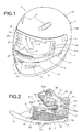
- a full-face-type helmet 1 is made up of a full-face-type head protecting cap body 2 to be worn on the head of a helmet wearer, a shield plate 4 capable of opening/closing a window opening 3 formed in the front surface of the head protecting body 2 to oppose the portion (i.e., the face) between the forehead and chin of the wearer, and a pair of right and left chin straps 8 attached to the inside of the head protecting body 2.
- the shield plate 4 is made of a transparent or translucent hard material such as polycarbonate or another hard synthetic resin.
- the shield plate 4 is pivotally attached to the head protecting body 2 with a pair of right and left attaching screws 5.
- the shield plate 4 closes the window opening 3 at the backward pivoting position shown in Fig. 1, and opens the window opening 3 at the forward pivoting position at which the shield plate 4 has pivoted upward from the backward pivoting position. At the intermediate position between these positions, the shield plate 4 can partly open the window opening 3.
- a tap 6 is formed on the shield plate 4. The tap 6 is held by the wearer with his fingers when the wearer is to pivot upward and downward the shield plate 4 forward and backward. An operating lever 7 is operated by the wearer when the wearer is to slightly pivot upward the shield plate 4 located at the backward pivoting position.
- the head protecting body 2 may incorporate one or a plurality of types of ventilator mechanisms.
- a pair of right and left air supply ports 11, serving also as exhaust ports, are formed in the chin region of the head protecting body 2 opposing the wearer's chin.
- An outlet port forming member 12 forms an outlet port through which air introduced from the air supply ports 11 flows upward along the inner surface of the shield plate 4.
- An operating tap 13 operates a shutter that opens/closes the outlet port formed by the outlet port forming member 12.
- a pair of right and left air supply port opening/closing shutters 14 are formed in the front region of the head protecting body 2 opposing the front of the head of the wearer.
- a pair of right and left exhaust port opening/closing shutters 15 are formed in the back region of the head protecting body 2 opposing the back of the head of the wearer.
- a breath guard 10 is formed near the chin region of the head protecting body 2 to be adjacent to the outlet port forming member 12.
- the head protecting body 2 is made up of a full-face-type outer shell 16 which forms the circumferential wall of the head protecting body 2, a lower rim member 17 having a substantially U-shaped cross-section and fixed to the outer shell 16 throughout the lower end of the outer shell 16 with an adhesive or the like, a rim member 19 for a window opening, which has a substantially E-shaped cross-section and fixed to the outer shell 16 with an adhesive or the like throughout the periphery of an window opening 18 formed in the outer shell 16 to form the window opening 3 of the head protecting body 2, a backing member 21 for the head, which is fixed to the outer shell 16 with an adhesive or the like in contact with the inner surface of the outer shell 16 in a front head region, a top head region, right and left side head regions and a back head region respectively corresponding to the front part, top part, right and left parts and back part of the head of the wearer, and a backing member 25 for the chin and cheek, which is fixed to the outer shell 16 with an adhesive or the
- the outer shell 16 can be made of a composite material formed by lining the inner surface of a strong shell body made of a hard synthetic resin, e.g., FRP, with a flexible sheet such as an unwoven fabric.
- the lower rim member 17 can be made of a soft synthetic resin such as foamed vinyl chloride or synthetic rubber.
- the rim member 19 can be made of an elastic material with high flexibility such as synthetic rubber.
- the backing member 21 is constituted by an impact-on-the-head absorbing liner (not shown) and a breathing backing cover 24 (see Fig. 6) for the head attached to the impact-on-the-head absorbing liner so as to cover almost the entire inner surface of the impact-on-the-head absorbing liner. As shown in Fig.
- the backing member 25 is constituted by an impact-on-the-chin-and-cheek absorbing liner 26 and a pair of left and right blockish inside pads 27a and 27b for the cheeks which are attached to the impact-on-the-chin-and-cheek absorbing liner 26 in contact with the inner surface of the impact-on-the-chin-and-cheek absorbing liner 26 in right and left cheek regions corresponding to the left and right cheeks of the wearer.
- Each of the body portions of the impact-on-the-head absorbing liner and the impact-on-the-chin-and-cheek absorbing liner 26 can be made of a material with appropriate rigidity and appropriate plasticity such as polystyrene foam or another synthetic resin.
- the body portion of the backing cover 24 can be made of a combination of woven fabric portions 31 and porous unwoven fabric portions 32 formed by laminating layers, each made of an elastic material with high flexibility such as urethane foam or another synthetic resin, on the surface (i.e., the outer surface) opposing the impact-on-the-head absorbing liner or two side surfaces.
- a front-side engaged member 33 and rear-side engaged member 34 are respectively attached to the front and rear end portions of the body portion of the backing cover 24 with a sewing thread, a tape, an adhesive or the like.
- a front-side engaging member and rear-side engaging member are respectively attached to the front and rear end portions of the body portion of the impact-on-the-head absorbing liner by fixing with rivets, washers (not shown) or the like, or with an adhesive, a tape or the like to almost oppose these front- and rear-side engaged members 33 and 34.
- a pair of left and right engaged studs 35 and 36 respectively formed on the front- and rear-side engaged members 33 and 34 on the backing cover 24 side are press-fitted in a pair of left and right engaging apertures respectively formed in the front- and rear-side engaging members on the impact-on-the-head absorbing liner through projection-recess engagement, thereby detachably attaching the backing cover 24 to the impact-on-the-head absorbing liner.
- the front- and rear-side engaged members 33 and 34 on the backing cover 24 side and the front- and rear-side engaging members on the impact-on-the-head absorbing liner can be made of a soft synthetic resin such as polyethylene.
- a pair of right and left positioning inserted portions 37 are formed on the front-side engaged member 33, which are to be inserted between the outer shell 16 and the impact-on-the-head absorbing liner.
- Appropriate numbers of ventilation openings 38, 39 and 40 are formed in the front-side engaged member 33, rear-side engaged member 34 and the body portion of the backing cover 24, respectively.
- a slit-like gap 30 is formed between the pair of woven fabric portions 31.
- the pair of left and right blockish inside pads 27a and 27b for the cheeks are symmetrical to each other.
- the blockish inside pad 27b for the right cheek will be described in detail with reference to Figs. 2, 3 and 4, and a detailed description on the blockish inside pad 27a for the left cheek will be omitted.
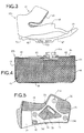
- the blockish inside pad 27b for the right cheek is made up of a pad main body 41 and an elastic and flexible, elongated thin platelike engaging member 42 attached near the lower end of the pad main body 41 with a sewing thread, a tape, an adhesive or the like.
- the pad main body 41 has a notch 43 to exclude an ear region corresponding to the right ear part of the wearer.
- the pad main body 41 has an almost forked shape to correspond to the right cheek part of the wearer and its vicinity (excluding the right ear part).
- the pad main body 41 is made up of a thick platelike cushion member 44 formed of one or a plurality of flexible, elastic materials such as urethane foam or another synthetic resin, and a bag-like member 45 made of a flexible sheet material such as cloth or artificial leather and covering the cushion member 44 almost entirely like a bag.
- a thick platelike cushion member 44 formed of one or a plurality of flexible, elastic materials such as urethane foam or another synthetic resin
- a bag-like member 45 made of a flexible sheet material such as cloth or artificial leather and covering the cushion member 44 almost entirely like a bag.
- Each of the cushion member 44 and bag-like member 45 has an almost forked shape to correspond to the pad main body 41. Accordingly, the cushion member 44 is accommodated in and attached to the bag-like member 45.
- the engaging member 42 is also attached to the bag-like member 45.
- the lower surface of the bag-like member 45 is almost entirely formed of an artificial leather sheet portion 47 such as vinyl leather.
- the lower portion of that surface of the bag-like member 45 which opposes the impact-on-the-chin-and-cheek absorbing liner 26 is formed of a porous unwoven fabric portion 48.
- the peripheral surface of the notch 43 of the bag-like member 45 is almost entirely formed of a porous unwoven fabric portion 49.
- the woven fabric portion 46, artificial leather portion 47 and porous unwoven fabric portions 48 and 49 make up a bag main body 51 of the bag-like member 45, of which the surface opposing the impact-on-the-chin-and-cheek absorbing liner 26 is open at its upper and central portions to form an opening 50.
- the woven fabric portion 46, artificial leather portion 47 and porous unwoven fabric portions 48 and 49 are not respectively limited to woven fabric, porous or nonporous unwoven fabric and artificial leather, but can be formed of an arbitrary flexible sheet material such as these materials, a synthetic resin sheet, paper, paper laminated with a synthetic resin, or natural leather.
- the opening 50 of the bag main body 51 of the bag-like member 45 is partly covered by a pair of inner and outer holding members 61 and 62 which are made of a thin platelike elastic material and vertically overlaid on each other.
- each of the inner and outer holding members 61 and 62 may be formed by integrally connecting a large number of substantially band-like portions to form a thin platelike shape as a whole (this thin platelike shape can have one or a plurality of apertures and/or one or a plurality of notches).
- each of the inner and outer holding members 61 and 62 may be obtained by punching a sheet material made of a small-flexibility elastic material, e.g., a soft synthetic resin such as polypropylene or polyethylene, or paper laminated with such a soft synthetic resin, into an appropriate shape, to have a flexibility as a whole.
- the thickness of this sheet material and accordingly the thicknesses of the inner and outer holding members 61 and 62 are preferably from 0.3 mm to 2.5 mm and more preferably from 0.5 mm to 1.8 mm generally from the viewpoint of practicality.
- the inner holding member 61 is formed of an upper portion 61a, a lower portion 61b and a connecting portion 61c which integrally connects the upper and lower portions 61a and 61b at the front end side, to form a substantially forked shape.
- the inner holding member 61 is attached to part of the periphery of the opening 50 of the bag main body 51 with a sewing thread, tape or adhesive at those portions of the upper and lower portions 61a and 61b and connecting portion 61c which extend along the notch 43 (i.e., at some portions of the periphery).
- the upper portion 61a has a plurality of openings 63.
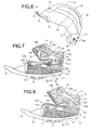
- Male portions (i.e., male hooks) 65a, 65b and 65c of round hooks serving as engaged studs or projections are attached near the rear ends of the upper and lower portions 61a and 61b and to the connecting portion 61c by fixing with rivets 67 or the like, as shown in Fig. 4.
- Three imaginary lines sequentially connecting the centers of the three male hooks 65a, 65b and 65c (in other words, engaging holes 66a, 66b and 66c to be described later) form a triangle.
- the outer holding member 62 is formed of an upper portion 62a, a lower portion 62b and a connecting portion 62c which integrally connects the upper and lower portions 62a and 62b at the front end side, to form a substantially forked shape.
- the outer holding member 62 is attached to the periphery of the opening 50 of the bag main body 51 with a sewing thread, tape or adhesive at some portions (i.e., some portions of the periphery) excluding the lower end of the upper portion 62a, the upper end of the lower portion 62b and rear end of the connecting portion 62c.
- Each of the upper and lower portions 62a and 62b has a plurality of openings 64.
- Notched engaging holes 66a and 66b are respectively formed around the openings 64 near the rear ends of the upper and lower portions 62a and 62b to correspond to the male hooks 65a and 65b, so that they are continuous to the corresponding openings 64.
- a notched engaging hole 66c is formed in the rear end side of the connecting portion 62c to correspond to the male hook 65c.
- the outer surfaces (see Fig. 4) of the lower portions of the annular male portions of the male hooks 65a, 65b and 65c are detachably fitted and fixed in the engaging holes 66a, 66b and 66c, respectively.
- the inner and outer holding members 61 and 62 are connected to each other through detachable recess-projection engagement of the engaged studs or projections comprised of the annular male portions of the male hooks 65a, 65b and 65c and the engaging holes 66a, 66b and 66c.
- the engaging member 42 has a notch 71 near its front end.
- the rear end of the engaging member 42 projects backward from the pad main body 41 to form an inserted portion 72, and the intermediate portion of the engaging member 42 has openings 73 for imparting flexibility and reducing weight.
- the engaging member 42 may be made of an elastic material, e.g., a soft synthetic resin such as polyethylene.
- a pair of right and left thin platelike support members 75 are attached to that surface (i.e., the inner surface) of the main body of the impact-on-the-chin-and-cheek absorbing liner 26, which is opposite to the outer shell 16, by adhesion or the like.
- Female portions (i.e., female hooks) 74a to 74c of the round hooks are attached to each support member 75 with rivets or the like to correspond to the male hooks 65a, 65b and 65c, respectively.
- the body portion of the impact-on-the-chin-and-cheek absorbing liner 26 may be partly covered with a flexible sheet such as porous unwoven fabric 76 and vinyl leather 77 in advance.
- This body portion has an opening 78 through which the corresponding chin strap 8 is to be inserted, and a recess 81 surrounding the opening 78 to make the corresponding chin strap 8 extend through it.
- An opening 79 is formed at the central portion of each support member 75 as well to correspond to the corresponding opening 78 and recess 81.
- An engaging pin 80 is formed on the main body portion to oppose the notch 71 of the engaging member 42.
- the male hooks 65a, 65b and 65c of the blockish inside pad 27b may be engaged with the female hooks 74a, 74b and 74c of the impact-on-the-chin-and-cheek absorbing liner 26 through recess-projection engagement.
- the engaging member 42 of the blockish inside pad 27b is inserted between the outer shell 16 and impact-on-the-chin-and-cheek absorbing liner 26 from below.
- the engaging pin 80 of the impact-on-the-chin-and-cheek absorbing liner 26 is relatively fitted in the notch 71 of the engaging member 42 from below in Fig. 5 and engaged with it through recess-projection engagement.
- the inserted portion 72 of the engaging member 42 is inserted between the outer shell 16 and backing member 21.
- the chin strap 8 inserted through the opening 78 of the impact-on-the-chin-and-cheek absorbing liner 26 is inserted in the notch 43 of the blockish inside pad 27b. To remove the blockish inside pad 27b from the impact-on-the-chin-and-cheek absorbing liner 26, operation opposite to that for attachment described above may be performed.
- the inner holding member 61 is brought outside the outer holding member 62, as shown in Fig. 7. Subsequently, the inner holding member 61 in the state shown in Fig. 7 is turned inside out from the front side to the rear side of the cushion member 44 and bag main body 51, so that it comes to the state shown in Fig. 8. In the state shown in Fig. 8, the inner holding member 61 does not exist above the opening 50 but merely the outer holding member 62 exists above the opening 50. Therefore, the cushion member 44 can be taken out of the bag main body 51 very easily while appropriately elastically deforming the outer holding member 62. When this cushion member 44 or another cushion member is to be put in the bag main body 51, operation opposite to that described above for removal may be performed.
- the inner holding member 61 To extract the annular male portions of the male hooks 65a, 65b and 65c respectively from the engaging holes 66a, 66b and 66c, the inner holding member 61 must be moved relative to the outer holding member 62 in different directions in units of combinations of the male hooks and engaging holes, as described in the above items (1), (2) and (3).
- the annular male portions of the male hooks 65a, 65b and 65c do not substantially undesirably come off from the respective engaging holes 66a, 66b and 66c upon application of an impact to helmet 1.
- the present invention is applied to a blockish inside pad for the cheek.
- the present invention can also be applied to various types of blockish inside pads other than the one for the cheek which is used for a helmet.
- two holding members 61 and 62 are provided to one bag-like member 45.
- one, three, or more holding members may be provided to one bag-like member 45.
- only one cushion member 44 is accommodated in one bag-like member 45.
- two or more cushion members may be accommodated in the bag-like member 45 in, e.g., a multilayered manner.
- the engaged studs or projection 65a to 65c of the recess-projection engaging mechanism with which the plurality of holding members 61 and 62 are detachably engaged with each other through recess-projection engagement, also serve as the engaged studs or projections of a recess-projection engaging mechanism with which the blockish inside pads 27a and 27b are detachably engaged with the head protecting body 2 through recess-projection engagement when they are to be built into the head protecting body 2.
- the latter engaged studs or projections may be separately formed on, e.g., the outer holding member 62.
- the two types of projection-recess engaging mechanisms are not always necessary. In this case, the latter projection-recess engaging mechanism may be replaced with another connecting mechanism such as a tape.
- the two holding members 61 and 62 when the two holding members 61 and 62 are connected to each other through recess-projection engagement, they are overlaid on each other such that one holding member 61 is located inside while the other holding member 62 is located outside.
- the two holding members 61 and 62 may be overlaid on each other such that one portion of one holding member 61 is located inside and the remaining portion of the holding member 61 is located outside, while one portion of the other holding member 62 is located outside and the remaining portion of the holding member 62 is located inside.
- the plurality of holding members 61 and 62 are detachably connected to each other with the recess-projection engaging mechanisms 65a to 65c and 74a to 74c.
- the plurality of holding members 61 and 62 may be detachably connected to each other with another connecting mechanism such as a hook engaging mechanism.
- the relationship between the engaged studs and corresponding engaging holes may be reversed individually.
- the engaging holes 66a, 66b and 66c form notched engaging holes.
- the engaging holes 66a, 66b and 66c may form independent engaging holes such as substantially circular holes.
- each of the holding members 61 and 62 has a substantially forked shape, and has the plurality of openings 63 and 64 for improving the elasticity and decreasing the weight.
- the holding member 61 or 62 need not have a forked shape, and the openings 63 and 64 can be omitted if necessary.
- the present invention is applied to the full-face-type helmet 1.
- the present invention can also be applied to a helmet of another type, i.e., a jet- or semijet-type helmet.
- each of the inner and outer holding members 61 and 62 is formed of an elastic sheet member such that the entire holding member has flexibility.
- only one (e.g., the inner holding member 61) of the inner and outer holding members 61 and 62 may have flexibility, wile the other may not have flexibility.
- the flexible holding member need not have flexibility entirely, and a flexible portion (e.g., a portion in the vicinity of an engaged projection or engaging hole) and a nonflexible portion may exist in a mixed manner.
Landscapes
- Helmets And Other Head Coverings (AREA)
Applications Claiming Priority (2)
| Application Number | Priority Date | Filing Date | Title |
|---|---|---|---|
| JP2000132552A JP4592870B2 (ja) | 2000-05-01 | 2000-05-01 | ヘルメット |
| JP2000132552 | 2000-05-01 |
Publications (3)
| Publication Number | Publication Date |
|---|---|
| EP1151684A2 true EP1151684A2 (fr) | 2001-11-07 |
| EP1151684A3 EP1151684A3 (fr) | 2005-02-16 |
| EP1151684B1 EP1151684B1 (fr) | 2008-04-02 |
Family
ID=18641233
Family Applications (1)
| Application Number | Title | Priority Date | Filing Date |
|---|---|---|---|
| EP01110044A Expired - Lifetime EP1151684B1 (fr) | 2000-05-01 | 2001-04-27 | Garniture de rembourrage intérieure pour casque et casque muni d'une telle garniture |
Country Status (4)
| Country | Link |
|---|---|
| US (1) | US6421841B2 (fr) |
| EP (1) | EP1151684B1 (fr) |
| JP (1) | JP4592870B2 (fr) |
| DE (1) | DE60133431T2 (fr) |
Cited By (1)
| Publication number | Priority date | Publication date | Assignee | Title |
|---|---|---|---|---|
| FR3152212A1 (fr) | 2023-08-24 | 2025-02-28 | Shark | Ensemble de garniture de rembourrage intérieure pour un casque, et casque associé |
Families Citing this family (53)
| Publication number | Priority date | Publication date | Assignee | Title |
|---|---|---|---|---|
| US6987839B1 (en) * | 2000-06-29 | 2006-01-17 | Cisco Technology, Inc. | Arrangement for converting telephone number formats for notification systems |
| US20040140691A1 (en) * | 2001-10-29 | 2004-07-22 | Toshiyuki Horimatsu | Shock absorbing material |
| MXPA03003843A (es) | 2002-05-01 | 2004-09-03 | Riddell | Casco de futbol americano. |
| AU2003247414A1 (en) | 2002-05-14 | 2003-12-02 | White Water Research And Safety Institute, Inc. | Protective headgear for whitewater use |
| US7207071B2 (en) * | 2004-06-18 | 2007-04-24 | Fox Racing, Inc. | Ventilated helmet system |
| JP4948893B2 (ja) * | 2006-05-09 | 2012-06-06 | 株式会社Shoei | ヘルメットおよびその脱着方法 |
| US8069499B2 (en) * | 2006-05-15 | 2011-12-06 | Shoei Co., Ltd. | Helmet shield attaching mechanism, and helmet attached with the same |
| DE102006031751B4 (de) * | 2006-07-04 | 2009-11-12 | Schuberth Gmbh | Integralhelm |
| JP4976153B2 (ja) * | 2007-02-06 | 2012-07-18 | 株式会社Shoei | ヘルメットサイズの調整方法 |
| US7987525B2 (en) * | 2007-04-13 | 2011-08-02 | Klim | Helmet |
| US9289024B2 (en) | 2007-04-16 | 2016-03-22 | Riddell, Inc. | Protective sports helmet |
| JP5041906B2 (ja) | 2007-08-07 | 2012-10-03 | 株式会社Shoei | ヘルメット |
| US8296868B2 (en) * | 2007-08-17 | 2012-10-30 | Easton Sports, Inc. | Adjustable hockey helmet |
| AR065444A1 (es) * | 2008-02-22 | 2009-06-10 | Jose Maria Rolla | Arnes con amortiguador para cascos |
| US20090260133A1 (en) * | 2008-04-18 | 2009-10-22 | Del Rosario John A | Impact Absorbing Frame and Layered Structure System for Safety Helmets |
| JP5159556B2 (ja) * | 2008-10-22 | 2013-03-06 | 株式会社Shoei | ヘルメットおよびその脱着方法 |
| JP4939586B2 (ja) * | 2009-10-19 | 2012-05-30 | 株式会社アライヘルメット | オープンフェースヘルメット |
| USD670870S1 (en) | 2011-05-09 | 2012-11-13 | A7 Helmet Systems, Llc | Helmet padding |
| USD670868S1 (en) | 2011-05-09 | 2012-11-13 | A7 Helmet Systems, Llc | Helmet padding |
| USD670869S1 (en) | 2011-05-09 | 2012-11-13 | A7 Helmet Systems, Llc | Helmet padding |
| USD666779S1 (en) | 2011-06-15 | 2012-09-04 | A7 Helmet Systems, Llc | Helmet padding |
| US9345282B2 (en) | 2011-07-27 | 2016-05-24 | Bauer Hockey, Inc. | Adjustable helmet for a hockey or lacrosse player |
| CA2784316C (fr) | 2011-07-27 | 2013-10-01 | Bauer Hockey Corp. | Casque de sport avec protection contre les impacts par rotation |
| US9763488B2 (en) | 2011-09-09 | 2017-09-19 | Riddell, Inc. | Protective sports helmet |
| WO2013039559A1 (fr) * | 2011-09-13 | 2013-03-21 | Cleva Robert E | Coiffe de protection à complémentarité de forme |
| US8458820B2 (en) | 2011-09-13 | 2013-06-11 | Robert E. Cleva | Form-fitting protective headwear |
| US8347419B1 (en) | 2011-09-13 | 2013-01-08 | Cleva Robert E | Form-fitting protective headwear |
| US8973171B2 (en) | 2011-09-13 | 2015-03-10 | Robert E. Cleva | Form-fitting protective headwear |
| US8713717B2 (en) * | 2011-09-13 | 2014-05-06 | Robert E. Cleva | Protective athletic headwear with open top |
| US8789212B2 (en) | 2011-09-13 | 2014-07-29 | Robert E. Cleva | Protective athletic headwear with open top |
| US10159296B2 (en) | 2013-01-18 | 2018-12-25 | Riddell, Inc. | System and method for custom forming a protective helmet for a customer's head |
| US9770060B2 (en) | 2013-02-12 | 2017-09-26 | Riddell, Inc. | Pad assemblies for a protective sports helmet |
| US9656148B2 (en) | 2013-02-12 | 2017-05-23 | Riddell, Inc. | Football helmet with recessed face guard mounting areas |
| JP2016539253A (ja) | 2013-12-06 | 2016-12-15 | ベル スポーツ, インコーポレイテッド | 可撓性多層ヘルメット及びその作製方法 |
| USD752822S1 (en) | 2014-02-12 | 2016-03-29 | Riddell, Inc. | Football helmet |
| JP6282491B2 (ja) * | 2014-03-05 | 2018-02-21 | 株式会社Shoei | 留め機構及びヘルメット |
| US10721987B2 (en) | 2014-10-28 | 2020-07-28 | Bell Sports, Inc. | Protective helmet |
| KR101772124B1 (ko) * | 2015-11-30 | 2017-09-12 | 주식회사 기도스포츠 | 헬멧의 탈착식 패드 체결 구조 및 이를 포함하는 헬멧 |
| US11033796B2 (en) | 2016-07-20 | 2021-06-15 | Riddell, Inc. | System and methods for designing and manufacturing a bespoke protective sports helmet |
| IT201600083163A1 (it) * | 2016-08-05 | 2018-02-05 | Nolangroup Spa | Casco con elemento di imbottitura rimovibile |
| USD850013S1 (en) | 2017-07-20 | 2019-05-28 | Riddell, Inc. | Internal padding assembly of a protective sports helmet |
| USD850011S1 (en) | 2017-07-20 | 2019-05-28 | Riddell, Inc. | Internal padding assembly of a protective sports helmet |
| USD850012S1 (en) | 2017-07-20 | 2019-05-28 | Riddell, Inc. | Internal padding assembly of a protective sports helmet |
| CN109752849B (zh) * | 2017-11-03 | 2021-05-18 | 宏达国际电子股份有限公司 | 头戴式显示装置 |
| CA3102923A1 (fr) * | 2018-06-07 | 2019-12-12 | VICIS, Inc. | Mousses d'ajustement a attenuation de choc |
| WO2020037279A1 (fr) | 2018-08-16 | 2020-02-20 | Riddell, Inc. | Système et procédé de conception et de fabrication d'un casque de protection |
| CA3169309A1 (fr) | 2018-11-21 | 2020-05-28 | Riddell, Inc. | Casque de sport recreatif de protection avec des composants fabriques de facon additive pour gerer des forces d'impact |
| USD927084S1 (en) | 2018-11-22 | 2021-08-03 | Riddell, Inc. | Pad member of an internal padding assembly of a protective sports helmet |
| ES3061988T3 (en) * | 2019-12-16 | 2026-04-08 | Ogk Kabuto Co Ltd | Helmet |
| US11730225B2 (en) * | 2020-11-20 | 2023-08-22 | LIFT Airborne Technologies LLC | Helmet liner coupling |
| JP7333352B2 (ja) * | 2021-01-19 | 2023-08-24 | 株式会社Shoei | ハーネスブラケット及びヘルメット |
| USD946833S1 (en) | 2021-05-21 | 2022-03-22 | Riddell, Inc. | Visor for a football helmet |
| IT202100018902A1 (it) * | 2021-07-16 | 2023-01-16 | Alpinestars Res Spa | Casco protettivo |
Family Cites Families (20)
| Publication number | Priority date | Publication date | Assignee | Title |
|---|---|---|---|---|
| US3843970A (en) * | 1973-03-19 | 1974-10-29 | M Marietta | Protective headgear |
| US3882547A (en) * | 1973-10-09 | 1975-05-13 | Riddell | Padding structure |
| US4282610A (en) * | 1978-01-16 | 1981-08-11 | The Kendall Company | Protective headgear |
| JPS6269811A (ja) * | 1985-09-24 | 1987-03-31 | ヤマハ発動機株式会社 | ヘルメツトの内張り構造 |
| JPH026606A (ja) * | 1988-06-14 | 1990-01-10 | Michio Arai | フルフェース型ヘルメット |
| JPH02289102A (ja) * | 1989-04-24 | 1990-11-29 | Yamaha Motor Co Ltd | ヘルメット等のマット |
| JPH0639721B2 (ja) | 1990-08-15 | 1994-05-25 | 昭栄化工株式会社 | ヘルメット |
| JPH0623527Y2 (ja) * | 1990-08-20 | 1994-06-22 | 昭栄化工株式会社 | ヘルメット |
| US5038779A (en) * | 1990-12-10 | 1991-08-13 | Barry Kevin P | Therapeutic garment |
| JPH079940U (ja) * | 1993-07-08 | 1995-02-10 | 大日本インキ化学工業株式会社 | 乗車用ヘルメット |
| JP2853850B2 (ja) * | 1996-03-01 | 1999-02-03 | 株式会社アライヘルメット | ヘルメットの内装体用パッド及びその内装体 |
| JPH108320A (ja) * | 1996-06-19 | 1998-01-13 | Arai Helmet:Kk | 乗車用安全ヘルメット |
| JP3358186B2 (ja) * | 1997-01-10 | 2002-12-16 | 株式会社ホンダアクセス | ヘルメット |
| JP3955127B2 (ja) * | 1997-05-19 | 2007-08-08 | 学 根本 | ヘルメット |
| BE1012651A5 (fr) * | 1997-07-09 | 2001-02-06 | Honda Access Kk | Casque. |
| JP3008397B2 (ja) * | 1997-07-09 | 2000-02-14 | 株式会社ホンダアクセス | ヘルメットの内装体 |
| US5825719A (en) * | 1997-10-16 | 1998-10-20 | Input/Output, Inc. | Dual-port air gun having a single shuttle |
| JP2904416B1 (ja) * | 1998-06-23 | 1999-06-14 | 株式会社アライヘルメット | フルフェース型ヘルメット |
| JP3004264B1 (ja) * | 1998-10-30 | 2000-01-31 | 株式会社アライヘルメット | フルフェース型ヘルメット |
| JP2000136421A (ja) * | 1998-10-30 | 2000-05-16 | T S Tec Kk | ヘルメットの内装構造 |
-
2000
- 2000-05-01 JP JP2000132552A patent/JP4592870B2/ja not_active Expired - Lifetime
-
2001
- 2001-04-27 DE DE60133431T patent/DE60133431T2/de not_active Expired - Lifetime
- 2001-04-27 EP EP01110044A patent/EP1151684B1/fr not_active Expired - Lifetime
- 2001-05-01 US US09/846,867 patent/US6421841B2/en not_active Expired - Lifetime
Cited By (1)
| Publication number | Priority date | Publication date | Assignee | Title |
|---|---|---|---|---|
| FR3152212A1 (fr) | 2023-08-24 | 2025-02-28 | Shark | Ensemble de garniture de rembourrage intérieure pour un casque, et casque associé |
Also Published As
| Publication number | Publication date |
|---|---|
| US20010034895A1 (en) | 2001-11-01 |
| EP1151684B1 (fr) | 2008-04-02 |
| JP4592870B2 (ja) | 2010-12-08 |
| EP1151684A3 (fr) | 2005-02-16 |
| US6421841B2 (en) | 2002-07-23 |
| DE60133431D1 (de) | 2008-05-15 |
| JP2001316928A (ja) | 2001-11-16 |
| DE60133431T2 (de) | 2009-04-09 |
Similar Documents
| Publication | Publication Date | Title |
|---|---|---|
| EP1151684B1 (fr) | Garniture de rembourrage intérieure pour casque et casque muni d'une telle garniture | |
| EP1743538B1 (fr) | Casque du type intégral | |
| US7854023B2 (en) | Helmet and method of removing the same | |
| US8800065B2 (en) | Helmet and method of removing the same | |
| JP4592871B2 (ja) | ヘルメット | |
| JP4976153B2 (ja) | ヘルメットサイズの調整方法 | |
| US6256797B1 (en) | Helmet and method of removing the same | |
| JP5159556B2 (ja) | ヘルメットおよびその脱着方法 | |
| US20130007950A1 (en) | Helmet | |
| JPH09241915A (ja) | ヘルメットの内装体用パッド及びその内装体 | |
| JP2002069738A (ja) | ヘルメット用チンカバーおよびこのチンカバーが取り付けられたヘルメット | |
| US12089686B2 (en) | Helmet | |
| JPH0638090Y2 (ja) | ヘルメット | |
| JPH10204717A (ja) | ヘルメット | |
| JPH1121716A (ja) | ヘルメットの内装体 | |
| JPH0444590Y2 (fr) | ||
| JPH11172517A (ja) | ヘルメット | |
| JPH0627613Y2 (ja) | ヘルメット | |
| JP3010621B2 (ja) | ヘルメット | |
| JPH0519296Y2 (fr) | ||
| JP2022170123A (ja) | ヘルメット |
Legal Events
| Date | Code | Title | Description |
|---|---|---|---|
| PUAI | Public reference made under article 153(3) epc to a published international application that has entered the european phase |
Free format text: ORIGINAL CODE: 0009012 |
|
| AK | Designated contracting states |
Kind code of ref document: A2 Designated state(s): AT BE CH CY DE DK ES FI FR GB GR IE IT LI LU MC NL PT SE TR |
|
| AX | Request for extension of the european patent |
Free format text: AL;LT;LV;MK;RO;SI |
|
| PUAL | Search report despatched |
Free format text: ORIGINAL CODE: 0009013 |
|
| AK | Designated contracting states |
Kind code of ref document: A3 Designated state(s): AT BE CH CY DE DK ES FI FR GB GR IE IT LI LU MC NL PT SE TR |
|
| AX | Request for extension of the european patent |
Extension state: AL LT LV MK RO SI |
|
| 17P | Request for examination filed |
Effective date: 20050512 |
|
| AKX | Designation fees paid |
Designated state(s): DE FR GB IT |
|
| 17Q | First examination report despatched |
Effective date: 20060907 |
|
| GRAP | Despatch of communication of intention to grant a patent |
Free format text: ORIGINAL CODE: EPIDOSNIGR1 |
|
| GRAS | Grant fee paid |
Free format text: ORIGINAL CODE: EPIDOSNIGR3 |
|
| GRAA | (expected) grant |
Free format text: ORIGINAL CODE: 0009210 |
|
| AK | Designated contracting states |
Kind code of ref document: B1 Designated state(s): DE FR GB IT |
|
| REG | Reference to a national code |
Ref country code: GB Ref legal event code: FG4D |
|
| REF | Corresponds to: |
Ref document number: 60133431 Country of ref document: DE Date of ref document: 20080515 Kind code of ref document: P |
|
| ET | Fr: translation filed | ||
| PLBE | No opposition filed within time limit |
Free format text: ORIGINAL CODE: 0009261 |
|
| STAA | Information on the status of an ep patent application or granted ep patent |
Free format text: STATUS: NO OPPOSITION FILED WITHIN TIME LIMIT |
|
| 26N | No opposition filed |
Effective date: 20090106 |
|
| REG | Reference to a national code |
Ref country code: FR Ref legal event code: PLFP Year of fee payment: 16 |
|
| REG | Reference to a national code |
Ref country code: FR Ref legal event code: PLFP Year of fee payment: 17 |
|
| REG | Reference to a national code |
Ref country code: FR Ref legal event code: PLFP Year of fee payment: 18 |
|
| PGFP | Annual fee paid to national office [announced via postgrant information from national office to epo] |
Ref country code: FR Payment date: 20200420 Year of fee payment: 20 Ref country code: DE Payment date: 20200420 Year of fee payment: 20 |
|
| PGFP | Annual fee paid to national office [announced via postgrant information from national office to epo] |
Ref country code: IT Payment date: 20200428 Year of fee payment: 20 Ref country code: GB Payment date: 20200427 Year of fee payment: 20 |
|
| REG | Reference to a national code |
Ref country code: DE Ref legal event code: R071 Ref document number: 60133431 Country of ref document: DE |
|
| REG | Reference to a national code |
Ref country code: GB Ref legal event code: PE20 Expiry date: 20210426 |
|
| PG25 | Lapsed in a contracting state [announced via postgrant information from national office to epo] |
Ref country code: GB Free format text: LAPSE BECAUSE OF EXPIRATION OF PROTECTION Effective date: 20210426 |