EP1215767A2 - Elektrischer Verbinder - Google Patents
Elektrischer Verbinder Download PDFInfo
- Publication number
- EP1215767A2 EP1215767A2 EP01129561A EP01129561A EP1215767A2 EP 1215767 A2 EP1215767 A2 EP 1215767A2 EP 01129561 A EP01129561 A EP 01129561A EP 01129561 A EP01129561 A EP 01129561A EP 1215767 A2 EP1215767 A2 EP 1215767A2
- Authority
- EP
- European Patent Office
- Prior art keywords
- article
- electric connector
- contact
- housing
- contacting point
- Prior art date
- Legal status (The legal status is an assumption and is not a legal conclusion. Google has not performed a legal analysis and makes no representation as to the accuracy of the status listed.)
- Granted
Links
Images









Classifications
-
- H—ELECTRICITY
- H01—ELECTRIC ELEMENTS
- H01R—ELECTRICALLY-CONDUCTIVE CONNECTIONS; STRUCTURAL ASSOCIATIONS OF A PLURALITY OF MUTUALLY-INSULATED ELECTRICAL CONNECTING ELEMENTS; COUPLING DEVICES; CURRENT COLLECTORS
- H01R13/00—Details of coupling devices of the kinds covered by groups H01R12/70 or H01R24/00 - H01R33/00
- H01R13/40—Securing contact members in or to a base or case; Insulating of contact members
- H01R13/42—Securing in a demountable manner
- H01R13/436—Securing a plurality of contact members by one locking piece or operation
-
- H—ELECTRICITY
- H01—ELECTRIC ELEMENTS
- H01R—ELECTRICALLY-CONDUCTIVE CONNECTIONS; STRUCTURAL ASSOCIATIONS OF A PLURALITY OF MUTUALLY-INSULATED ELECTRICAL CONNECTING ELEMENTS; COUPLING DEVICES; CURRENT COLLECTORS
- H01R13/00—Details of coupling devices of the kinds covered by groups H01R12/70 or H01R24/00 - H01R33/00
- H01R13/02—Contact members
- H01R13/22—Contacts for co-operating by abutting
- H01R13/24—Contacts for co-operating by abutting resilient; resiliently-mounted
- H01R13/2442—Contacts for co-operating by abutting resilient; resiliently-mounted with a single cantilevered beam
Definitions
- the present invention is an electric connector that is used to electrically connect two articles, each of which having a conductive part.
- This electric connector comprises a housing, which is fitted onto at least one of the articles, and a contact provided on the housing, and the contact comprises a connecting part, which is connected to a conductive part of a first article, a contacting point, which contacts a conductive part of a second article, and an elastic part, which undergoes elastic deformation when the contacting point is pressed, and at least either the housing or the contact is provided with a holding member, which holds the elastic part in an elastically deformed condition in advance in the direction of pressing the contacting point and prevents the restoring thereof.
- the costs are lowered through the reduction in the number of electric connector in use.
- the work of connecting the conductive part to the electric connector which is exemplified by crimping, can be done by a single operation, the costs are lowered through the improved workability.
- a separate joining means such as a screw is not needed to join the two articles together, and the costs are reduced through the elimination of any joining means.
- the space occupied by the electric connector is reduced in comparison with the conventional connecting structure wherein a pair of a male crimp connector and a female crimp connector are used, and the connecting structure is compactified.
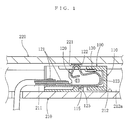
- Fig. 1 is a sectional view of the electric connector of the first embodiment when it is used by fitting it onto the first article.
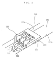
- Fig. 2 is a perspective view of the electric connector of the first embodiment when it is used by fitting it onto the first article.
- Fig. 6A and Fig. 6B are sectional views showing the contact of the electric connector of the first embodiment.
- Fig. 6A shows the contact before it contacts the second article
- Fig. 6B shows the contact after it contacts the second article.
- Fig. 9 is a sectional view of the electric connector of the first embodiment when it is fitted onto both the first article and the second article.
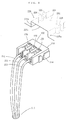
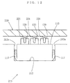
- Fig. 12 is a front view of the electric connector of the third embodiment when it is used by fitting it onto the first article.
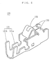
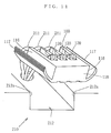
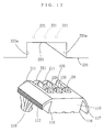
- the elastic part 123 is a cantilevered leaf spring, which is bent approximately into a U shape, and the elastic part 123 is branched into two or more parts, and two or more free ends of the elastic part 123 are provided with a contacting point 122, respectively.
- At least either the housing 110 or the contact 120 is provided with a holding member 130, which holds the elastic part 123 in an elastically deformed condition in advance in the direction of pressing the contacting point 122 and prevents the restoring thereof.
- a case wherein two sets of a contacting point 122 and an elastic part 123 are used is shown as an example.
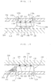
- Fig. 16 shows another connecting form of the electric connector 100 of the above-mentioned fourth embodiment.
- the housing 110 is fitted onto the first article 210.
- locking holes 215 are formed in the first article 210, and the locking pawls 118 extend protrusively from the face of the housing 110, which is opposite, in the height direction, to the face on which the contacting points 122 are exposed.
- the electric connector 100 is held in such a way that the face being opposite, in the height direction, to the contacting points 122 opposes to the first article 210, and the locking pawls 118 are fitted onto the first article 210.
- the method of electrically connecting the articles 210, 220 with the electric connector 100 in this connecting form is similar to that of the connecting form shown in Fig. 1 through Fig. 3.
Landscapes
- Coupling Device And Connection With Printed Circuit (AREA)
- Multi-Conductor Connections (AREA)
- Connector Housings Or Holding Contact Members (AREA)
- Details Of Connecting Devices For Male And Female Coupling (AREA)
- Connections By Means Of Piercing Elements, Nuts, Or Screws (AREA)
Applications Claiming Priority (2)
| Application Number | Priority Date | Filing Date | Title |
|---|---|---|---|
| JP2000384530 | 2000-12-18 | ||
| JP2000384530A JP2002184502A (ja) | 2000-12-18 | 2000-12-18 | 電気コネクタ |
Publications (3)
| Publication Number | Publication Date |
|---|---|
| EP1215767A2 true EP1215767A2 (de) | 2002-06-19 |
| EP1215767A3 EP1215767A3 (de) | 2005-07-06 |
| EP1215767B1 EP1215767B1 (de) | 2007-02-07 |
Family
ID=18851958
Family Applications (1)
| Application Number | Title | Priority Date | Filing Date |
|---|---|---|---|
| EP01129561A Expired - Lifetime EP1215767B1 (de) | 2000-12-18 | 2001-12-11 | Elektrischer Verbinder |
Country Status (8)
| Country | Link |
|---|---|
| US (2) | US20020077002A1 (de) |
| EP (1) | EP1215767B1 (de) |
| JP (1) | JP2002184502A (de) |
| KR (1) | KR20020048873A (de) |
| CN (1) | CN1230942C (de) |
| DE (1) | DE60126464D1 (de) |
| HK (1) | HK1046779B (de) |
| TW (1) | TW530442B (de) |
Cited By (4)
| Publication number | Priority date | Publication date | Assignee | Title |
|---|---|---|---|---|
| EP2375500A1 (de) * | 2010-03-04 | 2011-10-12 | Tyco Electronics Nederland B.V. | Skalierbares Kontaktelement für elektrische Steckverbinder |
| WO2012002940A1 (en) * | 2010-06-29 | 2012-01-05 | Teradyne, Inc. | Zero insertion force scrubbing contact |
| EP2375473A3 (de) * | 2010-04-07 | 2014-11-26 | Black & Decker Inc. | Batteriepack-Anschlusssystem |
| CN111262102A (zh) * | 2020-01-21 | 2020-06-09 | 中山市叶子照明科技有限公司 | 连接器及轨道灯用灯具及用电器 |
Families Citing this family (29)
| Publication number | Priority date | Publication date | Assignee | Title |
|---|---|---|---|---|
| JP4214501B2 (ja) * | 2000-12-18 | 2009-01-28 | 日本圧着端子製造株式会社 | 電気コネクタ |
| KR20040100764A (ko) * | 2003-05-24 | 2004-12-02 | 삼성전자주식회사 | 백라이트 어셈블리 및 이를 갖는 액정표시장치 |
| US20050148230A1 (en) * | 2004-01-07 | 2005-07-07 | Flynn James D. | Coupling device that includes opposing pawls engagable into opposing pawl catches |
| JP4170278B2 (ja) * | 2004-03-19 | 2008-10-22 | タイコエレクトロニクスアンプ株式会社 | コンタクト及び電気コネクタ |
| TWM300874U (en) * | 2006-06-02 | 2006-11-11 | Advanced Connectek Inc | Battery connector |
| US7607952B2 (en) * | 2007-05-15 | 2009-10-27 | Fci Americas Technology, Inc. | Battery contact |
| US7527532B2 (en) * | 2007-05-15 | 2009-05-05 | Fci Americas Technology, Inc. | Battery contact |
| US7497715B2 (en) * | 2007-06-11 | 2009-03-03 | Hon Hai Precision Ind. Co., Ltd. | Cable connector assembly for solar device |
| CN201667425U (zh) * | 2009-11-20 | 2010-12-08 | 富士康(昆山)电脑接插件有限公司 | 电连接器 |
| US8636066B2 (en) * | 2010-03-12 | 2014-01-28 | Baker Hughes Incorporated | Method of enhancing productivity of a formation with unhydrated borated galactomannan gum |
| USD643477S1 (en) | 2010-07-02 | 2011-08-16 | Wing Hing Manufacturing Co. Ltd. | Bubble machine |
| USD642629S1 (en) | 2010-07-02 | 2011-08-02 | Wing Hing Manufacturing Co. Ltd. | Bubble machine |
| CN102377042A (zh) * | 2010-08-06 | 2012-03-14 | 国际商业机器公司 | 电连接元,电连接器及其制造方法 |
| DE102011002661A1 (de) * | 2011-01-13 | 2012-07-19 | Robert Bosch Gmbh | Kontaktelement zur elektrischen Direktkontaktierung von Leiterplatten |
| DE102011076962A1 (de) * | 2011-06-06 | 2012-12-06 | Robert Bosch Gmbh | Direktsteckelement, insbesondere für ein Fahrzeugsteuergerät |
| DE102011076992B4 (de) * | 2011-06-06 | 2021-12-09 | Robert Bosch Gmbh | Direktsteckelement mit geschütztem Direktkontakt |
| JP5952626B2 (ja) * | 2012-04-19 | 2016-07-13 | 矢崎総業株式会社 | 基板コネクタ |
| JP2014011048A (ja) * | 2012-06-29 | 2014-01-20 | Fujitsu Component Ltd | コンタクト部材 |
| KR20150145515A (ko) | 2014-06-20 | 2015-12-30 | (주)한신단자공업 | 전자기기용 커넥터 |
| DE102015211725B4 (de) * | 2014-06-27 | 2020-10-08 | Dai-Ichi Seiko Co., Ltd. | Verbinderanschluss und Verbinder hiermit |
| JP5862755B1 (ja) * | 2014-12-12 | 2016-02-16 | 第一精工株式会社 | コネクタ端子 |
| JP5896009B1 (ja) * | 2014-12-12 | 2016-03-30 | 第一精工株式会社 | コネクタ端子 |
| CN104638400A (zh) * | 2015-02-04 | 2015-05-20 | 青岛鼎信通讯股份有限公司 | 线路板电性连接弹片及固定装置 |
| CN106571545B (zh) | 2015-10-12 | 2019-03-12 | 莫列斯有限公司 | 导电端子及电连接器组合 |
| JP6311995B2 (ja) * | 2015-03-31 | 2018-04-18 | 株式会社オートネットワーク技術研究所 | カードエッジコネクタ |
| JP6350876B2 (ja) * | 2015-06-18 | 2018-07-04 | 株式会社オートネットワーク技術研究所 | コネクタ |
| US10320096B2 (en) * | 2017-06-01 | 2019-06-11 | Avx Corporation | Flexing poke home contact |
| DE102017125270B3 (de) * | 2017-10-27 | 2019-03-21 | Wago Verwaltungsgesellschaft Mbh | Abgriffsteckverbinder |
| DE102018203991A1 (de) * | 2018-03-15 | 2019-09-19 | Zf Friedrichshafen Ag | Vorrichtung zur Herstellung einer Verbindung sowie Anordnung |
Family Cites Families (66)
| Publication number | Priority date | Publication date | Assignee | Title |
|---|---|---|---|---|
| US3680035A (en) | 1970-02-25 | 1972-07-25 | Amp Inc | Pcb hinged pod connector |
| US3742430A (en) | 1972-02-24 | 1973-06-26 | Ford Motor Co | Electrical terminal |
| US4087151A (en) * | 1976-07-28 | 1978-05-02 | Magnetic Controls Company | Printed circuit card edge connector with normalling contacts |
| JPS5710471Y2 (de) | 1977-05-31 | 1982-03-01 | ||
| JPS559019A (en) | 1978-07-04 | 1980-01-22 | Lion Corp | Preparation of tertiary long-chain aliphatic methylamine |
| US4209217A (en) | 1978-10-26 | 1980-06-24 | Thomas & Betts Corporation | Housing for removable mounting on printed circuit board |
| US4295009A (en) * | 1980-03-07 | 1981-10-13 | Amp Incorporated | Piezoelectric audio transducer mounting and electrical connector |
| JPS5712671A (en) | 1980-06-27 | 1982-01-22 | Nec Corp | Printer |
| FR2497007A1 (fr) | 1980-12-23 | 1982-06-25 | Labinal | Perfectionnements aux boitiers de connexions electriques et aux organes de connexion destines a equiper de tels boitiers |
| JPS5844775A (ja) | 1981-09-11 | 1983-03-15 | Konishiroku Photo Ind Co Ltd | アモルフアスシリコン半導体装置及びその製造方法 |
| US4778407A (en) | 1982-12-23 | 1988-10-18 | Amp Incorporated | Electrical connector plug for conductors on closely spaced centers |
| US4558270A (en) * | 1983-09-06 | 1985-12-10 | James P. Liautaud | Battery charging adapter for a battery charger for a portable battery operated transceiver |
| FR2566589B1 (fr) * | 1984-06-21 | 1987-08-21 | Labinal | Connecteur electrique pour carte de circuit imprime simple face |
| US4737850A (en) | 1985-07-03 | 1988-04-12 | Rca Corporation | Apparatus for noise reducing composite video signal |
| JPH01142167A (ja) | 1987-11-25 | 1989-06-05 | Toto Ltd | 二重床構造 |
| JPH01168970A (ja) | 1987-12-22 | 1989-07-04 | Toho Chem Ind Co Ltd | ポリエステル系繊維材料の難燃加工方法 |
| US5231659A (en) | 1989-05-16 | 1993-07-27 | Alcatel Business Systems | Telephone handset with transducer assembly |
| JPH0665092B2 (ja) | 1989-06-27 | 1994-08-22 | 矢崎総業株式会社 | コネクタ |
| JPH0472488A (ja) | 1990-07-13 | 1992-03-06 | Toshiba Corp | 流体圧縮機 |
| JPH0455779U (de) * | 1990-09-18 | 1992-05-13 | ||
| JPH04135176A (ja) | 1990-09-26 | 1992-05-08 | Heiji Yasui | 無気孔型砥石の目直し法 |
| JP2535607Y2 (ja) | 1991-10-18 | 1997-05-14 | 矢崎総業株式会社 | コネクタ |
| JP2598581Y2 (ja) * | 1991-12-03 | 1999-08-16 | 矢崎総業株式会社 | コネクタ |
| US5236833A (en) | 1992-03-17 | 1993-08-17 | Nestec S.A. | Diacetyl production |
| JPH0575981U (ja) | 1992-03-18 | 1993-10-15 | 矢崎総業株式会社 | ガラス板用コネクタ |
| NL9200559A (nl) | 1992-03-26 | 1993-10-18 | Du Pont Nederland | Connector. |
| JP2611081B2 (ja) | 1992-03-30 | 1997-05-21 | 矢崎総業株式会社 | コネクタの端子係止構造 |
| JPH0631094A (ja) | 1992-07-15 | 1994-02-08 | Toshiba Corp | 二槽式洗濯機の溢水装置 |
| US5403204A (en) | 1993-03-03 | 1995-04-04 | Sumitomo Wiring Systems, Ltd. | Joint connector |
| FR2711849A1 (fr) * | 1993-10-27 | 1995-05-05 | Amp France | Borne électrique à contact à déplacement d'isolant et ressort de renfort. |
| JP2529814B2 (ja) | 1993-11-11 | 1996-09-04 | 矢崎総業株式会社 | コネクタ |
| US5484295A (en) | 1994-04-01 | 1996-01-16 | Teledyne Electronic Technologies | Low profile compression electrical connector |
| JPH0822871A (ja) | 1994-07-05 | 1996-01-23 | Sumitomo Electric Ind Ltd | 電子ユニット用コネクタ |
| US5605150A (en) * | 1994-11-04 | 1997-02-25 | Physio-Control Corporation | Electrical interface for a portable electronic physiological instrument having separable components |
| JP3106282B2 (ja) | 1995-04-13 | 2000-11-06 | 矢崎総業株式会社 | コネクタ |
| FR2737352B1 (fr) | 1995-07-28 | 1997-08-29 | Itt Composants Instr | Connecteur electrique pour le raccordement d'une carte a circuit(s) integre(s) a contact |
| JP3191909B2 (ja) | 1995-09-06 | 2001-07-23 | 矢崎総業株式会社 | 嵌合誘導機構付きコネクタ |
| JPH0982431A (ja) | 1995-09-19 | 1997-03-28 | Whitaker Corp:The | 電気コネクタ及びその製造方法 |
| JPH09237650A (ja) | 1996-02-28 | 1997-09-09 | Harness Sogo Gijutsu Kenkyusho:Kk | コネクタ付ユニットの連結構造 |
| DE19611422C2 (de) | 1996-03-22 | 2001-06-07 | Tyco Electronics Logistics Ag | Verbinder für die elektrische Verbindung von zwei Leiterplatten miteinander |
| JPH09306576A (ja) | 1996-05-08 | 1997-11-28 | Thomas & Betts Corp <T&B> | バッテリィ用端子 |
| JPH09320672A (ja) | 1996-05-29 | 1997-12-12 | Yazaki Corp | コネクタ |
| CN1177675A (zh) | 1996-08-01 | 1998-04-01 | 住友电装株式会社 | 可解锁的锁合连接器 |
| JP4140667B2 (ja) | 1996-08-01 | 2008-08-27 | 住友電装株式会社 | コネクタ |
| JPH10255931A (ja) | 1997-03-14 | 1998-09-25 | Dai Ichi Denshi Kogyo Kk | 電気コネクタ |
| JP3363078B2 (ja) | 1997-04-11 | 2003-01-07 | タイコエレクトロニクスアンプ株式会社 | 電気コネクタ |
| JP3547034B2 (ja) * | 1997-07-10 | 2004-07-28 | 矢崎総業株式会社 | コネクタ嵌合方法及びそれに用いるコネクタ |
| BR9802812A (pt) | 1997-08-29 | 1999-11-03 | Whitaker Corp | terminal para curto-circuito e conector. |
| JPH11144801A (ja) | 1997-11-07 | 1999-05-28 | Yazaki Corp | コネクタ |
| JP3463856B2 (ja) | 1998-03-05 | 2003-11-05 | 矢崎総業株式会社 | コネクタ接続構造 |
| JP3598811B2 (ja) | 1998-05-14 | 2004-12-08 | 住友電装株式会社 | 短絡端子とこれを組み込んだ嵌合検知用コネクタ |
| US6022224A (en) | 1998-07-22 | 2000-02-08 | International Business Machines Corporation | Shock mount connector for head disk assembly |
| US5980322A (en) | 1998-09-01 | 1999-11-09 | 3Com Corporation | Electrical connector having a fusible link for use between media connectors and computer communications cards |
| JP3685302B2 (ja) | 1998-11-10 | 2005-08-17 | 矢崎総業株式会社 | スプライス吸収コネクタ |
| JP2000231961A (ja) | 1998-12-08 | 2000-08-22 | Sumitomo Wiring Syst Ltd | コネクタ |
| US6102722A (en) | 1998-12-28 | 2000-08-15 | Lucent Technologies Inc. | Upgradeable communication connector |
| JP3286783B2 (ja) | 1999-02-18 | 2002-05-27 | 日本航空電子工業株式会社 | コンタクト |
| US6217396B1 (en) | 1999-07-06 | 2001-04-17 | Hon Hai Precision Ind. Co., Ltd. | Electrical connector with U-shaped spring contacts |
| US6126458A (en) * | 1999-07-13 | 2000-10-03 | Yazaki North America, Inc. | Bussed electrical center assembly with connector pre-set |
| US6099356A (en) * | 1999-07-19 | 2000-08-08 | Hon Hai Precision Ind. Co., Ltd. | Compression connector |
| US6309262B1 (en) | 1999-10-21 | 2001-10-30 | Hewlett-Packard Company | Bifurcated contact with a connecting member at the tip of the contact that provides redundant contact points |
| JP3534393B2 (ja) | 2000-04-14 | 2004-06-07 | インターナショナル・ビジネス・マシーンズ・コーポレーション | 電子部品ユニットの電気的接続構造、コンピュータ装置及び電子機器 |
| JP2002033154A (ja) | 2000-07-17 | 2002-01-31 | Yazaki Corp | ジョイントコネクタ |
| JP2002184489A (ja) | 2000-12-14 | 2002-06-28 | Japan Aviation Electronics Industry Ltd | コネクタ |
| JP2002184507A (ja) | 2000-12-18 | 2002-06-28 | Jst Mfg Co Ltd | 電気コネクタ |
| JP4214501B2 (ja) | 2000-12-18 | 2009-01-28 | 日本圧着端子製造株式会社 | 電気コネクタ |
-
2000
- 2000-12-18 JP JP2000384530A patent/JP2002184502A/ja active Pending
-
2001
- 2001-12-03 TW TW090129848A patent/TW530442B/zh not_active IP Right Cessation
- 2001-12-11 EP EP01129561A patent/EP1215767B1/de not_active Expired - Lifetime
- 2001-12-11 DE DE60126464T patent/DE60126464D1/de not_active Expired - Lifetime
- 2001-12-13 US US10/017,987 patent/US20020077002A1/en not_active Abandoned
- 2001-12-14 KR KR1020010079338A patent/KR20020048873A/ko not_active Ceased
- 2001-12-18 CN CNB011439106A patent/CN1230942C/zh not_active Expired - Fee Related
-
2002
- 2002-11-14 HK HK02108252.4A patent/HK1046779B/zh not_active IP Right Cessation
-
2003
- 2003-05-23 US US10/445,182 patent/US7153173B2/en not_active Expired - Fee Related
Cited By (4)
| Publication number | Priority date | Publication date | Assignee | Title |
|---|---|---|---|---|
| EP2375500A1 (de) * | 2010-03-04 | 2011-10-12 | Tyco Electronics Nederland B.V. | Skalierbares Kontaktelement für elektrische Steckverbinder |
| EP2375473A3 (de) * | 2010-04-07 | 2014-11-26 | Black & Decker Inc. | Batteriepack-Anschlusssystem |
| WO2012002940A1 (en) * | 2010-06-29 | 2012-01-05 | Teradyne, Inc. | Zero insertion force scrubbing contact |
| CN111262102A (zh) * | 2020-01-21 | 2020-06-09 | 中山市叶子照明科技有限公司 | 连接器及轨道灯用灯具及用电器 |
Also Published As
| Publication number | Publication date |
|---|---|
| HK1046779A1 (en) | 2003-01-24 |
| KR20020048873A (ko) | 2002-06-24 |
| CN1230942C (zh) | 2005-12-07 |
| HK1046779B (zh) | 2006-05-26 |
| US20030211787A1 (en) | 2003-11-13 |
| EP1215767B1 (de) | 2007-02-07 |
| TW530442B (en) | 2003-05-01 |
| US20020077002A1 (en) | 2002-06-20 |
| JP2002184502A (ja) | 2002-06-28 |
| EP1215767A3 (de) | 2005-07-06 |
| CN1360362A (zh) | 2002-07-24 |
| US7153173B2 (en) | 2006-12-26 |
| DE60126464D1 (de) | 2007-03-22 |
Similar Documents
| Publication | Publication Date | Title |
|---|---|---|
| EP1215767B1 (de) | Elektrischer Verbinder | |
| JP3311997B2 (ja) | コネクタ | |
| EP1215768B1 (de) | Elektrischer Verbinder | |
| JP2002367697A (ja) | コンタクトとこれを装着した電気コネクタ | |
| US5941722A (en) | Crimp connector | |
| EP1215766A2 (de) | Elektrischer Verbinder | |
| CN101359788A (zh) | 连接器及连接器端子构造 | |
| JPH02244574A (ja) | コネクタ | |
| US7462040B1 (en) | Electrical connector for circuit board | |
| US6994596B2 (en) | Terminal fitting, a connector provided therewith and method of forming a terminal fitting | |
| US6203359B1 (en) | Insulation displacement connection connector | |
| KR100571903B1 (ko) | 역끼워 맞춤 방지 커넥터 | |
| US5342219A (en) | Terminal-locking construction | |
| CN220189933U (zh) | 电连接器外壳和电连接器 | |
| US6454617B1 (en) | Electrical connector with improved terminals | |
| JP2000067988A (ja) | 圧接形電気コネクタ及びその組立体 | |
| JPH0735313Y2 (ja) | コネクタ | |
| JP2022007479A (ja) | 接続端子 | |
| JP3527656B2 (ja) | 圧接ジョイントコネクタ | |
| JP2023111108A (ja) | 端子接続構造 | |
| JP2022023654A (ja) | コネクタ | |
| JP2006286652A (ja) | 電気コネクタ | |
| KR200464159Y1 (ko) | 탭터미널 및 이를 포함하는 터미널 어셈블리 | |
| JP2006286652A5 (de) | ||
| JP2003045540A (ja) | 接続端子 |
Legal Events
| Date | Code | Title | Description |
|---|---|---|---|
| PUAI | Public reference made under article 153(3) epc to a published international application that has entered the european phase |
Free format text: ORIGINAL CODE: 0009012 |
|
| AK | Designated contracting states |
Kind code of ref document: A2 Designated state(s): AT BE CH CY DE DK ES FI FR GB GR IE IT LI LU MC NL PT SE TR |
|
| AX | Request for extension of the european patent |
Free format text: AL;LT;LV;MK;RO;SI |
|
| RIC1 | Information provided on ipc code assigned before grant |
Ipc: 7H 01R 12/16 B Ipc: 7H 01R 13/436 B Ipc: 7H 01R 13/50 B Ipc: 7H 01R 13/73 B Ipc: 7H 01R 13/24 A Ipc: 7H 01R 13/415 B Ipc: 7H 01R 12/22 B |
|
| PUAL | Search report despatched |
Free format text: ORIGINAL CODE: 0009013 |
|
| AK | Designated contracting states |
Kind code of ref document: A3 Designated state(s): AT BE CH CY DE DK ES FI FR GB GR IE IT LI LU MC NL PT SE TR |
|
| AX | Request for extension of the european patent |
Extension state: AL LT LV MK RO SI |
|
| 17P | Request for examination filed |
Effective date: 20050810 |
|
| AKX | Designation fees paid |
Designated state(s): DE FR GB IT NL |
|
| GRAP | Despatch of communication of intention to grant a patent |
Free format text: ORIGINAL CODE: EPIDOSNIGR1 |
|
| GRAS | Grant fee paid |
Free format text: ORIGINAL CODE: EPIDOSNIGR3 |
|
| GRAA | (expected) grant |
Free format text: ORIGINAL CODE: 0009210 |
|
| AK | Designated contracting states |
Kind code of ref document: B1 Designated state(s): DE FR GB IT NL |
|
| PG25 | Lapsed in a contracting state [announced via postgrant information from national office to epo] |
Ref country code: NL Free format text: LAPSE BECAUSE OF FAILURE TO SUBMIT A TRANSLATION OF THE DESCRIPTION OR TO PAY THE FEE WITHIN THE PRESCRIBED TIME-LIMIT Effective date: 20070207 |
|
| REG | Reference to a national code |
Ref country code: GB Ref legal event code: FG4D |
|
| REF | Corresponds to: |
Ref document number: 60126464 Country of ref document: DE Date of ref document: 20070322 Kind code of ref document: P |
|
| NLV1 | Nl: lapsed or annulled due to failure to fulfill the requirements of art. 29p and 29m of the patents act | ||
| EN | Fr: translation not filed | ||
| PLBE | No opposition filed within time limit |
Free format text: ORIGINAL CODE: 0009261 |
|
| STAA | Information on the status of an ep patent application or granted ep patent |
Free format text: STATUS: NO OPPOSITION FILED WITHIN TIME LIMIT |
|
| 26N | No opposition filed |
Effective date: 20071108 |
|
| PG25 | Lapsed in a contracting state [announced via postgrant information from national office to epo] |
Ref country code: DE Free format text: LAPSE BECAUSE OF FAILURE TO SUBMIT A TRANSLATION OF THE DESCRIPTION OR TO PAY THE FEE WITHIN THE PRESCRIBED TIME-LIMIT Effective date: 20070508 |
|
| PG25 | Lapsed in a contracting state [announced via postgrant information from national office to epo] |
Ref country code: IT Free format text: LAPSE BECAUSE OF FAILURE TO SUBMIT A TRANSLATION OF THE DESCRIPTION OR TO PAY THE FEE WITHIN THE PRESCRIBED TIME-LIMIT Effective date: 20070207 Ref country code: FR Free format text: LAPSE BECAUSE OF FAILURE TO SUBMIT A TRANSLATION OF THE DESCRIPTION OR TO PAY THE FEE WITHIN THE PRESCRIBED TIME-LIMIT Effective date: 20070928 |
|
| PG25 | Lapsed in a contracting state [announced via postgrant information from national office to epo] |
Ref country code: FR Free format text: LAPSE BECAUSE OF FAILURE TO SUBMIT A TRANSLATION OF THE DESCRIPTION OR TO PAY THE FEE WITHIN THE PRESCRIBED TIME-LIMIT Effective date: 20070207 |
|
| PGFP | Annual fee paid to national office [announced via postgrant information from national office to epo] |
Ref country code: GB Payment date: 20101221 Year of fee payment: 10 |
|
| GBPC | Gb: european patent ceased through non-payment of renewal fee |
Effective date: 20111211 |
|
| PG25 | Lapsed in a contracting state [announced via postgrant information from national office to epo] |
Ref country code: GB Free format text: LAPSE BECAUSE OF NON-PAYMENT OF DUE FEES Effective date: 20111211 |