EP1225609A2 - Eletromagnet und Betätigungsmechanik für einen Schalter - Google Patents
Eletromagnet und Betätigungsmechanik für einen Schalter Download PDFInfo
- Publication number
- EP1225609A2 EP1225609A2 EP01122198A EP01122198A EP1225609A2 EP 1225609 A2 EP1225609 A2 EP 1225609A2 EP 01122198 A EP01122198 A EP 01122198A EP 01122198 A EP01122198 A EP 01122198A EP 1225609 A2 EP1225609 A2 EP 1225609A2
- Authority
- EP
- European Patent Office
- Prior art keywords
- iron core
- permanent magnet
- coil
- electromagnet
- stationary
- Prior art date
- Legal status (The legal status is an assumption and is not a legal conclusion. Google has not performed a legal analysis and makes no representation as to the accuracy of the status listed.)
- Granted
Links
Images






Classifications
-
- H—ELECTRICITY
- H01—ELECTRIC ELEMENTS
- H01H—ELECTRIC SWITCHES; RELAYS; SELECTORS; EMERGENCY PROTECTIVE DEVICES
- H01H33/00—High-tension or heavy-current switches with arc-extinguishing or arc-preventing means
- H01H33/60—Switches wherein the means for extinguishing or preventing the arc do not include separate means for obtaining or increasing flow of arc-extinguishing fluid
- H01H33/66—Vacuum switches
- H01H33/666—Operating arrangements
- H01H33/6662—Operating arrangements using bistable electromagnetic actuators, e.g. linear polarised electromagnetic actuators
-
- H—ELECTRICITY
- H01—ELECTRIC ELEMENTS
- H01F—MAGNETS; INDUCTANCES; TRANSFORMERS; SELECTION OF MATERIALS FOR THEIR MAGNETIC PROPERTIES
- H01F7/00—Magnets
- H01F7/06—Electromagnets; Actuators including electromagnets
- H01F7/08—Electromagnets; Actuators including electromagnets with armatures
- H01F7/16—Rectilinearly-movable armatures
- H01F7/1607—Armatures entering the winding
- H01F7/1615—Armatures or stationary parts of magnetic circuit having permanent magnet
-
- H—ELECTRICITY
- H01—ELECTRIC ELEMENTS
- H01F—MAGNETS; INDUCTANCES; TRANSFORMERS; SELECTION OF MATERIALS FOR THEIR MAGNETIC PROPERTIES
- H01F7/00—Magnets
- H01F7/06—Electromagnets; Actuators including electromagnets
- H01F7/08—Electromagnets; Actuators including electromagnets with armatures
- H01F7/16—Rectilinearly-movable armatures
- H01F7/1607—Armatures entering the winding
- H01F7/1623—Armatures having T-form
-
- H—ELECTRICITY
- H01—ELECTRIC ELEMENTS
- H01F—MAGNETS; INDUCTANCES; TRANSFORMERS; SELECTION OF MATERIALS FOR THEIR MAGNETIC PROPERTIES
- H01F7/00—Magnets
- H01F7/06—Electromagnets; Actuators including electromagnets
- H01F7/08—Electromagnets; Actuators including electromagnets with armatures
- H01F7/121—Guiding or setting position of armatures, e.g. retaining armatures in their end position
- H01F7/122—Guiding or setting position of armatures, e.g. retaining armatures in their end position by permanent magnets
-
- H—ELECTRICITY
- H01—ELECTRIC ELEMENTS
- H01H—ELECTRIC SWITCHES; RELAYS; SELECTORS; EMERGENCY PROTECTIVE DEVICES
- H01H51/00—Electromagnetic relays
- H01H51/22—Polarised relays
- H01H51/2209—Polarised relays with rectilinearly movable armature
Definitions
- the present invention relates to an electromagnet and as well to an actuating mechanism using thereof for a switching device, and in particular to an electromagnet for restraining demagnetization of a permanent magnet, and as well to a reliable operating mechanism using thereof for a switching device.
- an electric power driven spring actuating mechanism As to the actuating mechanism for a switching device, there have been provided an electric power driven spring actuating mechanism, and a hydraulic or pneumatic actuating mechanism. These mechanism have a large number of components so as to have a link mechanism which is complicated, resulting in a relatively high manufacturing cost.
- An operating mechanism using an electromagnet is used as one of measures for simplifying the link mechanism.
- JP-A-5-234475 discloses a vacuum contactor in which an electromagnet is used for turn-on operation so that a closing spring which has been stored with energy is released simultaneously with the turn-on operation in order to open contacts.
- JP-A-10-249092 a plunger is provided extending through two turn-on and -off coils so that both turn-on and turn-off are carried by electromagnet.
- JP-A-2000-249092 discloses an actuating mechanism which maintains a turn-on condition with the use of an attraction force of a permanent magnet, and turn-off operation is carried out with the use of springs for driving movable members, which are provided respectively, by reversely energizing a coil with coil current. In this case, it is advantageous since only a single coil is required for both turn-on and turn-off.
- a permanent magnet may be a rare-earth samarium cobalt group magnet, a neodymium group magnet, an alnico group magnet, a ferrite group magnet or the like. If the neodymium group magnet which has a high residual magnetic flux density and which has a relatively low cost is used, an electromagnet can be small-sized and manufactured at a relatively low cost.
- the neodymium group magnet has a high magnetic coercive force, that is, 1,000 KA/m so as to require a magnetized electric field which is higher than 2,000 KA/m (corresponding to a magnetic flux density of 2.5 T). Accordingly, it is unpractical to magnetize a permanent magnet with a coil of an incorporated electromagnet, and accordingly, a magnet has to be incorporated after being magnetized.
- an electromagnet for a actuating mechanism for a switching device In the case of application of an electromagnet for a actuating mechanism for a switching device, reliable operation for a long term greater than 20 years and by a huge number of operating times are required. Accordingly, factors which cause demagnetization of a permanent magnet should be eliminated as possible as it can.
- An electromagnet incorporating a permanent magnet as disclosed in the JP-A-2000-249092, a backing magnetic field is applied to the permanent magnet, direct thereto so as to carry out cut-off operation. The repetition of application of reverse energy to the permanent magnet causes a risk of demagnetization of the permanent magnet or lowering of the use life thereof.
- a magnetic resistance as viewed from a coil becomes higher. Since the permeability of a permanent magnet is substantially equal to that of the air, a gap which is equal to a sum of a stroke length and the thickness of the permanent magnet is present at the time of a start of operation, and accordingly, a greater ampere turn is required.
- metrication errors caused during manufacture are inevitable for the thickness of the permanent magnet and the core, and the gap between the permanent magnet and the movable core which is opposed to the former and which can extend and retract, at an end of the stroke of the latter varies. Further, this gap causes the turn-on characteristic, the cut-off characteristic and the turn-on condition holding force (attraction force) to vary.
- the allowable range for metrication errors that is, the tolerance be strictly managed, the manufacture of an inexpensive electromagnet could be hardly be produced.
- the present invention is devised in order to solve the above-mentioned problems, and an object of the present invention is to provide an electromagnet having a long use life and a high degree of efficiency, in which no backing magnetic field is applied to a permanent magnet, and further, no permanent magnet is present in a magnetic path which is created by a coil current, and as well to provided an actuating mechanism for a switching device, using the electromagnet.
- Another object of the present invention is to provide an electromagnet in which the gap between the permanent magnet and the movable core which is opposed to the former and which can extend and retract can be simply adjusted.
- an electromagnet comprising a coil, a movable iron core which is moved on the center axis of the coil, a stationary iron core which is provided so as to cover upper, lower and outer peripheral surfaces of the coil, and a permanent magnet located in a gap defined by the movable iron core and the stationary iron core, wherein the movable core is attracted to the stationary core by a magnetic field produced by the permanent magnet.
- an electromagnet comprising a coil, a movable iron core which is moved on the center axis of the coil, a stationary iron core which is provided so as to cover upper, lower and outer peripheral surfaces of the coil, the stationary core is provided, on such a side that the movable iron core is inserted, with a magnetic protrusion, and the movable iron core being composed of a plunger and a steel plate secured to one end part of the plunger so that an end face of the plunger and the stationary iron core, and the steel plate and the protrusion are opposed to each other in the same directions, respectively, and a permanent magnet provided in a zone which is defined by the plunger, the protrusion, the steel plate and the stationary iron core.
- an electromagnet comprising a coil, a movable iron core which is moved on the center axis of the coil, a stationary iron core which is provided so as to cover upper, lower and outer peripheral surfaces of the coil, the stationary core is provided, on such a side that the movable iron core is inserted, with a magnetic protrusion, the movable iron core being composed of a plunger and a steel plate secured to one end part of the plunger, and a permanent magnet provided in a gap defined by the plunger, the protrusion, the steel plate and the stationary iron core, a side surface of the steel plate and the protrusion being opposed to each other, and an end face of the plunger and the stationary iron core, and the steel plate and the permanent magnet being opposed to in the same direction, respectively.
- the electromagnet as mentioned above, which incorporates a power source circuit for selectively applying a forward or reverse current to the coil, and accordingly, when the forward current is applied, a magnetic field is produced in a direction the same as a direction of a magnetic field produced by the permanent magnet so as to effect attraction, and when the reverse current is applied, the magnetic field produced by the permanent magnet is cancelled so as to effect release action.
- an electromagnet including a coil, a movable iron core which is moved on the center axis of the coil, a stationary core configured to cover both axially end surfaces and the outer peripheral surface of the coil, and a power source for applying a forward current and a reverse current to the coil, wherein the movable iron core is moved toward the stationary core when the forward current is applied to the coil, characterized in that the stationary iron core includes an iron core upper member configured to cover one of the axial end surfaces of the coil, a permanent magnet is located on the upper surface of the stationary iron core upper member while the movable iron core includes a planer plate member having a surface opposed to the upper surface of the stationary iron core with the permanent magnet intervening therebetween, and a plunger member having a cylindrical surface opposed to the inner peripheral surface of the coil, the inner peripheral surface of the stationary iron core upper member and the cylindrical surface of the plunger member defines therebetween a gap g1 which is smaller than the axial thickness t of the stationary core of the permanent
- a magentic member may be interposed between the end surface of the plunger member on the planer plate side, and the planar plate member.
- the permanent magnet may be the one selected from a group consisting of a rare earth samarium-cobalt group magnet, an alnico group magnet a ferrite group magnet.
- an actuating mechanism for a switching device incorporating the above-mentioned electromagnet, separatable contacts, a cut-off spring for opening the contacts, a power source circuit for selectively applying forward and reverse current to the coil wherein when the forward current is applied, the cut-off spring is urged while the contacts are turned on so as to hold the turn-on condition by attraction force of the permanent magnet, and when the reverse current is applied to the coil, a magnetic field produced by the permanent magnet is cancelled out so that the opening and closing device is cut off by a force of the cut-of spring.
- the electromagnet constituted as mentioned above, in which a magnet field causing a reverse current to run through the coil does never extend through the permanent magnet upon cut-off, the permanent magnet can be prevented from being reversely excited and further, no permanent magnet is present in a magnetic path created by coil current so that no factor of demagnetizing the permanent magnet is present, resulting in the possible use of a neodymium group magnet, thereby it is possible to provide an electromagnet having a long use life and a high degree of efficiency.
- the gap between the permanent magnet and the movable iron core which is opposed to the former and which can extend and retract, at a stroke end can be adjusted. That is, the characteristics thereof can be stabilized without causing the tolerance of components of the permanent magnet to be strict, thereby it is possible to provide an inexpensive electromagnet with a high degree of accuracy.
- the switching device can be small-sized and inexpensive and can offer a high degree of reliability.
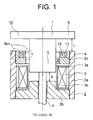
- Fig. 1 is a sectional view illustrating an electromagnet 10 in the first embodiment of the present invention
- the electromagnet 10 has an axially symmetric structure.
- reference numerals are attached to elements shown on the right half of the figure for explaining the structure of the electromagnet 10, and a magnetic field B (indicated by the chain line) which is effected by a permanent magnet 12 and current running through a coil 3 is shown in the left half of the figure.
- a movable core 1 is composed of a plunger 5 extending through the coil on the center axis thereof, and a dick-like steel plate 6 secured to one end part of the plunger 5, and is coupled to a load W by means of a nonmagnetic coupling member 7 secured to an end part of the plunger 5.
- the load W effects a force which urges the movable iron core 10 upward under attraction of the electromagnet 10.
- a stationary iron core 2 is composed of a steel pipe 2a, a convex steel member 2b and a ring-like steel plate 2c which are all magnetic.
- the convex steel member 2b and the ring-like steel plate 2c may be attached in such a manner that they are screwed into opposite ends of the steel pipe 2a, as shown.
- the steel pipe 2a and the convex steel member 2b, or the steel pipe 2a and the ring-like steel plate 2c may be produced from a columnar material by cutting.
- the convex steel member 2b is used in this embodimetn, instead thereof, a mere planar plate may be used.
- the convex steel member 2b may be formed in one unit body, or may be formed of two steel plates which are joined to each other.
- the coil 3 is composed of a bobbin 3a made of insulator or nonmagnetic metal (aluminum, copper or the like), and windings 3b.
- the ring-like steel plate 2c is screwed into the steel pipe 2a, being relatively deep therein, and has a configuration formed with a magnetic protrusion 4.
- the electromagnet 10 has such a configuration that the end face of the plunger 5 and the convex steel member 2b, and the disc-like steel plate 6 and the protrusion 4 are opposed in the same direction, respectively.
- the distance g between the side surface of the plunger 15 and the ring-like steel plate 2c is shorter than the stroke length of the movable iron core.
- the distance X between the end face of the plunger 5 and the convex steel member 2b is set to be shorter than a distance L between the disc-like steel plate 6 and the protrusion 4, and upon completion of attraction, the plunger 5 and the convex steel member 2b are made into contact with each other.
- a ring-like permanent magnet 12 is located in a zone defined by the plunger 12, the disc-like steel plate 6, the protrusion 4 and the ring-like steel plate 2c, and is secured on the ring-like steel plate 2c.
- Reference numeral 13 denotes a retainer which is made of nonmagnetic material such as SUS, for the permanent magnet 12, and which is secured by being screwed into the steel pipe 2b.
- a gap is defined between the permanent magnet 12 and the protrusion 4 by the retainer 13 in order to prevent magnetic fluxes produced by the permanent magnet 12 from being shortcircuited by the protrusion 4.
- Fig. 2 shows a condition juste after a start of attraction
- Fig. 3 shows a condition just before completion of attraction
- Fig. 4 is a condition just after completion of attraction
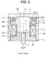
- Fig. 5 is a condition during release operation.
- the release operation is effected by passing a current through the coil 3 in a direction reverse to that of the current applied during the attracting operation.
- a magnetic field produced by this coil current runs through the magnetic path 02 so as to cancel out the magnetic field Bm produced by the permanent magnet 12. Accordingly, the attracting force FO exerted to the end face of the plunger 5 is decreased, and therefore, the movable iron core 1 is moved upward by a load force.
- an attracting force Fr is effected between the disc-like steel plate 6 and the protrusion 4 by the magnetic field Bc at the same time, should excessive current be applied to the coil 3, attracting operation would possibly be again effected.
- it is required to provide a means for limiting the coil current through a balance with the load forcer, and for cutting off the coil current at once after completion of the release operation.
- a permanent magnet 12 is present on a magnetic path created by coil current, and accordingly, the permanent magnet 12 is directly excited in a reverse direction during release operation. With the repetitions of application of reverse power to the permanent magnet 12, there would be a risk of demagnetization.
- the permanent magnet 12 is located in a gap defined by the movable iron core 1 and the stationary iron core 2, that is, in a zone which are magnetically shielded, and according, the magnetic field Bc produced by the coil current can be prevented from acting directly upon the permanent magnet 12. Even during the release operation, reverse power is never applied to the permanent magnet 12. There by it is possible to provide a magnetic disc 12 which can eliminate the risk of demagnetization, and which can have a long use life and a high degree of the magnet.
- the magnetic permeability of the permanent magnet 12 is substantially equal to that of the air, and if the permanent magnet 1 is present in the magnetic path created by the coil current, the magnetic resistance as viewed from the coil becomes higher. Upon a start of the operation, a gap which is the sum of the stroke and the thickness of the permanent magnet 12 is present, and accordingly, the ampere turn required for the operation is increased. However, since no permanent magnet is present on the magnetic path created by the coil current in the electromagnet 10 according to this embodiment, the magnetic resistance is low, and accordingly, the efficiency becomes higher.
- Fig. 6 is a sectional view illustrating an electromagnet 10 in a second embodiment of the present invention.
- a movable iron core 1 is composed of a plunger 5 extending through a coil 3 along the center axis of the latter, and a disc-like steel plate 6 secured to one end part of the plunger, and is coupled to a load through the intermediary of a nonmagnetic coupling member 7 secured to the other end part of the plunger 5.
- a stationary iron core 2 is composed of a steel pipe 2a, a convex steel member 2b and a ring-like steel plate 2c which are all magnetic. The convex steel member 2b and the ring-like steel plate 2c may be attached to the opposite ends of the steel pipe 2a, being screwed thereinto.
- the convex steel member 2b may be manufactured in one unit body, but it may be formed of two steel plates connected to each other.
- the coil 3 is composed of a bobbin 3a made of an insulator or a nonmagnetic metal (aluminum, copper or the like), and windings 3b.
- the ring-like permanent magnet 12 is secured on the ring-like steel plate 2c.
- reference numeral 15 denotes a pipe made of a nonmagnetic material such as SUS, and is fixed to the steel pipe 2a, the permanent magnet 12 being interposed therebetween. Since no large force is exerted to the pipe 15, it may be fixed by means of screws. The reason why the pipe 15 is made of a nonmagnetic material is such that the magnetic field of the permanent magnet 12 should be prevented from shortcircuited by the pipe 15.
- a lid 17 made of a nonmagnetic material is attached to one end part of the pipe 15, and a rod 8 secured to the movable core 1 extend thererthrough. Thus, axial deviation of the movable iron core 1 is prevented by the lid 17, the convex steel member 2b, the coupling member 7 and the rod 8.
- the distance X between the end face of the plunger 5 and the convex steel pipe 2b is shorter than the distance L between the disc-like steel plate 6 and the permanent magnet 12 in order to prevent the disc-like steel plate 6 from impinging upon the permanent magnet 12 so as to damage the latter.
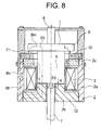
- Figs. 6 to 9 are sectional views illustrating the electromagnet 10, reference numerals for explaining the structure thereof being indicated in the right side part of the figure while a configuration of magnetic fields is shown in the left side part thereof.
- Fig. 6 shows a condition just after a start of attraction.
- Both distance X between the end face of the plunger 5 and the convex steel member 2b and distance L between the disc-like steel plate 6 and the permanent magnet 12 are longer than a distance g between the permanent magnet 12 and the plunger 5, and the magnetic field Bm created by the permanent magnet 12 only affects upon a part around the permanent magnet 12 as shown in Fig. 6.
- a drive force exerted to the movable iron core 1 is extremely small.
- the magnetic field Bc created by the coil current exerts an attracting force FO to the end face of the plunger 5, and accordingly, the movable iron core 1 starts its downward movement.
- the magnetic flux ⁇ c created by the coil current passes through a magnetic path 04. It is required to previously set the direction of the coil current and the direction of the polarity of the permanent magnet 12 so as to extend the magnetic field Bc created by the coil current and the magnetic field Bm of the permanent magnet Bm in a direction indicated by the arrow shown in Fig. 6. It is noted that the direction of the magnetic field Bc and the direction of the magnetic field Bm may be reversed from each other at the same time.
- a condition shown in Fig. 7 is immediately effected.
- the gap L between the disc-like steel plate 6 and the permanent magnet 12 is decreased so as to be shorter than the gap g between the plunger 5 and the ring-like steel plate 2c (g > L), and accordingly, the magnetic field Bm of the permanent magnet 12 passes through a magnetic path 05. That is, as the movable iron core 1 advances, the attracting force FO is exerted to the end face of the plunger 5, and an attracting force F1 is also effected between the disc-like steel plate 6 and the permanent magnet 12. Further, the electromagnet Bm of the permanent magnet 12 passes through opposed surfaces of the plunger 5 and the convex steel member 2b, and accordingly, the attracting force FO becomes further larger.
- the release operation is carried out by energizing the coil 3 with a current in a direction reverse to that during attraction, as shown in Fig. 8.
- the magnetic field Bc created by the coil current runs through a magnetic path 06 so as to cancel out the magnetic field Bm created by the permanent magnet 12, the attraction force FO is decreased, and accordingly, the movable iron core 1 is moved upward by the load force.
- the magnetic field created by the coil current does not directly affect upon the permanent magnet 12, and accordingly, no reverse energy is exerted even during release operation.
- a risk of demagnetization of the permanent magnet 12 can be avoided, and therefore, the electromagnet can have a long use life and a high degree of reliability.
- the permeability of the permanent magnet 12 is substantially equal to that of the air, and accordingly, should the permanent magnet 12 be present in the magnetic path created by the coil current, the magnetic resistance as viewed from the coil would become higher.
- the electromagnet in this embodiment can offer the following technical effects and advantages.
- the electromagnet in the first embodiment causes such a problem that attraction is again effected during release operation if excessive current is applied to the coil 3 since the attracting force F1 is effected between the disc-like steel plate 6 and the magnetic protrusion 4 by the magnetic field Bc created by the coil current.
- it is required to provide a measure for limiting the coil current through the balance with the load force, and cutting off the coil current just after completion of release operation.
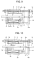
- Figs. 9 and 10 are sectional views illustrating an electromagnet 10 in this embodiment, when a switching device which is coupled to the electromagnet is turned on (Fig. 9) and when the switching device which is coupled to the electromagnet is turned off (Fig. 10), respectively.
- the turn-on condition and the turn-off condition which will be taken in the following description, are conditions of the electromagnet obtained when the switching device which is coupled to the electromagnet is turned on and off, respectively.
- the coil 3 is composed of a bobbin 3a made of an insulator or nonmagnetic metal (aluminum, copper or the like), and windings 3b.
- the electromagnet 10 as shown is composed of the coil 3, a movable iron core adapted to be moved on the center axis of the coil 3 and made of a magnetic material, a stationary iron core configured to cover axially opposite end surfaces and the outer peripheral surface of the coil 3 and made of a magnetic material, a power source which is not shown, for applying a forward current and a reverse current to the coil.
- the movable iron core is moved in a direction toward the stationary iron core, that is, in a direction from the right to the left as viewed in the figure.
- the right and the left sides of Fig. 9 correspond respectively to the upper and lower sides in view of the direction of the movement of the movable iron core.
- the stationary iron core is composed of a square planar plate 2d which is a stationary iron core upper member configured to cover one of the opposite end surface of the coil 3, and which is formed in its center part with a circular opening concentric with the coil 3, a square planar plate 2f which is a stationary iron core lower member configured to cover the other of the opposite end surfaces of the coil, and which is formed in its center part with a circular opening concentric with the coil 3, and a steel pipe 2e which is held between the two square planar plates 2d, 2f and which covers the outer peripheral surface of the coil 3, a cylinder 2g which arranged on the upper surface of the square planar plate 2f, concentric with the steel pipe 2e.
- the square planar plate 2d, the square planar plate 2f, the steel pipe 2e, and the cylinder 2g are all made of magnetic materials.
- the square planar plate 2f and the cylinder 2g are fixed together by screws, but may be welded together. Further, they may, of course, be integrally formed by cutting one and the same material.
- a disc-like permanent magnet 12 formed at its center with a circular opening is arranged on the square planar plate 2d, being attracted thereto, and is secured thereto with an adhesive.
- the permanent magnet 12 may be made of any one of a material of a neodymium group, a samarium group, an alnico group, a neodymium bond group and a ferrite group.
- the permanent magnet 12 as shown is a single ring magnet, it should not be in an integral ring-like shape, but planar magnets having different shapes such a rectangular shape, a circular shape or the like may be distributed on the square planar plate 2d. However, even in this case, it is required to set the areas of the surfaces of the magnets opposed to a cylindrical planar plate 6a which will be detailed later so as to effect a required attracting force.
- the movable iron core is composed of a nonmagnetic rod 19 piercing through the opening of the square planar plate 2d, the opening of the square planar plate 2f, the steel pipe 2e and the cylinder 2g at their centers, a magnetic cylindrical plunger 15 fitted on and fixed to the rod 19, and the magnetic cylindrical planar plate 6a which is arranged on the upper side of the plunger 5 through the intermediary of a thin plate 21 which is a magnetic member and which is fixed to the rod 19.
- the lower surface of the cylindrical planar plate 6a is opposed to the upper surface of the square planar plate 2d with the permanent magnet 12 intervening therebetween, and the outer peripheral surface of the plunger 5 is opposed to the inner peripheral surface of the coil 3.
- the outer diameter of the plunger 5 is smaller than any of the inner diameter of the coil 3, the diameter of the center opening of the permanent magnet 12 and the diameter of the center opening of the square planar plate 2d, and accordingly, it can axially movable therethrough.
- the outer diameter of the cylindrical planar plate 6a is larger than the diameter of the center opening of the permanent magnet 12, and accordingly, it can not pass through the center opening of the permanent magnet 12.
- the plunger 5 and the cylindrical planar plate 6a are secured to the rod 19, threadedly or by means of a retainer.
- the center opening of the permanent magnet 12 and the center opening of the square planar plate 2d are concentric with each other and have an equal diameter. Further, the thickness t of the permanent magnet 12 is set to be larger than the gap g1 between the inner peripheral surface of the center opening of the square planar plate 2d and the outer peripheral surface of the plunger 5.
- the outer diameter of cylinder 2g is smaller than the inner diameter of the coil 3, and is set to be equal to the outer diameter of the plunger 5. Further, the inner diameter of the cylinder 2g is set so as to allow the rod 19 to freely pass therethrough. That is, the lower surface of the plunger 5 is opposed to the upper surface of the cylinder 2g, and accordingly, when the movable iron core is axially moved leftward, the movable limit thereof is determined by a point where the lower surface of the plunger 5 comes into contact with the upper surface of the cylinder 2g.
- a nonmagnetic pipe 15a (which is made of stainless steel in this embodiment) is arranged on the upper side of the permanent magnet 12, concentric with the coil 3, and is held between the permanent magnet 12 and a square planer plate 18 which may be made of magnetic or nonmagnetic materials. Holes are formed in the four corners or two diagonal corners of the square planar plate 2f, the square planar plate 2d and the square planar plate 18. The holes can receive therethrough rods 14 having their opposite end parts formed with threads. By fastening the opposite end parts of the rods 14 with nuts, there are all fixed together.
- the square planar plate 18 and the square planar plate 2f are formed therein with bores which are concentric with the coil, and through which the rod 19 can pass, and these bores are fitted therein with bearings such as dry bearings so as to reduce the friction with respect to the rod 19 sliding therethrough, thereby it is possible to save maintenance works.
- the holding condition is effected by the attraction force (produced by a magnetic flux ⁇ 1). That is, in the turn-on condition, the gap g3 between the lower surface of the plunger 5 and the upper surface of the cylinder 2g is held to be zero, that is, the lower surface of the plunger 5 and the upper surface of the cylinder 2g are held so as to be made into contact with each other. Instead of direct contact between the lower surface of the plunger 5 and the upper surface of the cylinder 2g, a thin nonmagnetic material may be held therebetween.
- the number of thin plates 21 to be held between the plunger 5 and the cylindrical planar plate 6a, which have been previously prepared and which have an equal thickness, is changed in order to adjust the size of the gap g2 between the permanent magnet 12 and the cylindrical planar plate 6a to a desired value.
- the reason why the gap g2 is required, is such that, when the cylindrical planar plate 6a bumps directly upon the permanent magnet 12 during turn-on operation, the permanent magnet 12 is demagnetized, causing the use life of the permanent magnet 12 to be shortened.
- the gap g2 is decreased to a small value which is possibly zero so as to decrease the magnetic resistance in order to increase the attraction force.
- the permanent magnet 12 is thinned, or even though the bulk of the permanent magnet 12 is reduced by decreasing its outer surface for attracting the square planar plate 2d, a conventional attracting force can be ensured.
- the cost of the permanent magnet 12, which greatly depends upon the bulk of the permanent magnet, can be reduced, thereby it is possible to provide a small-sized and inexpensive electromagnet.
- the gap 2g in a turn-on condition can be set to a nearly desired constant value, the attraction force and the turn-on and -off characteristics of the permanent magnet can be stabilized, thereby it is possible to enhance the reliability of the permanent magnet.
- plates having slightly different thickness which have been previously prepared are used by selecting an appropriate thickness, singularly or in combination in order to adjust the above-mentioned gap.
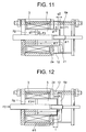
- a current (forward current) is applied from the power source which is not shown to the coil 3 so that the coil produces a magnetic field in the same direction as that effected by the permanent magnet 12. That is, the coil current and the permanent magnet 12 produce magnetic fluxes ⁇ 1, ⁇ 2 as shown in Fig. 11 so as to produce an attracting force for moving the cylindrical planar plate 6a leftward in the figure, that is, a force for attracting the movable iron core to the stationary core.
- This attraction force is produced both gaps between the plunger 5 and the cylinder 2g and between the cylindrical plate 6a and the permanent magnet 12.
- the force F1 is effected between the cylindrical plate 6a and the permanent magnet 12, and the force F2 is effected between the plunger 12 and the cylinder 2g.
- the force F2 during turn-on operation is produced by a magnetic flux obtained by synthesizing the magnetic flux ⁇ 2 and ⁇ 1.
- a current reverse to the current during turn-on operation is applied to the coil 3 from the power source which is not shown.
- the sum of the force F1 produced in the gap between the cylindrical plate 6a and the permanent magnet 12 by the magnetic flux ⁇ 1 and the force F2 produced in the gap between the plunger 5 and the cylinder 2g by the magnetic flux ⁇ 1 is greater than a force FO which is applied to the rod 19 in the rightward direction in the figure, by a cut-off spring which is not shown. That is, the force of the permanent magnet 12 overcomes the force of the cut-off spring, and accordingly, the turn-on condition is held.
- the thickness t of the permanent magnet 12 is set to be greater than the gap g1 between the inner peripheral surface of the center opening of the square planar plate 2d and the outer peripheral surface of the plunger 5, the magnetic flux ⁇ 5 produced by the reverse current does not extend through the permanent magnet 12 as shown in Fig. 12. It is because the magnetic permeability of the permanent magnet 12 is substantially equal to that of the air. The magnetic flux ⁇ 5 produced by the reverse current passes through a magnetic path having a low magnetic resistance, as shown in Fig. 12. Should the permanent magnet be applied with the reverse magnetic flux continuously for a long time, the demagnetization would be caused. However, according to the present invention, since no reverse magnetic flux is applied to the permanent magnet. The probability of demagnetization becomes less, thereby it is possible to provide an electromagnet having a long use life and a high degree of reliability.
- an electromagnet 10 stated in the embodiment 1 to the embodiment 3 is applied in an actuating mechanism for a switching device.
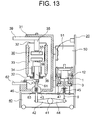
- Fig. 9 is a lateral sectional view for a three-phase switching device 20 in which the electromagnet 10 stated in the embodiment 2 is applied.
- the vacuum switching device in this specification, the permanent magnet 10 according to the present invention can be applied in other circuits breakers including a gas switching device. Further, while explanation will be made of such an arrangement that the electromagnet 10 stated in the embodiment 2 is applied, the electromagnet stated in the embodiment 1 or the embodiment 2 may be also applied.
- the vacuum switching device 20 is composed of vacuum bulbs 30, an actuating mechanism part 40, an insulator frame 31, a control circuit 51 and a manipulation space 50 for accommodating the electromagnet 10.
- the vacuum bulbs 30 are arranged for three phases in the depthwise direction of the surface of the figure. Three vacuum bulbs 30 are coupled to one another by a shaft 41 in the operating mechanism 40, and are actuated by the single electromagnet 10.
- a vacuum is held in each of the vacuum bulbs 30 by a vacuum container composed of upper and lower end plates 32 and an insulator cylinder 33.
- a stationary contact 37 and a movable contact 38 are arranged in the vacuum bulb 30, and are adapted to make contact with each other or separate from each other so as to effect turn-on and off operation.
- the stationary contact 37 is fixed to a stationary conductor 35, and is electrically connected to a stationary side feeder 39.
- the movable contact 38 is fixed to a movable conductor 36, and is connected to a movable side feeder 62 through the intermediary of a flexible conductor 61.
- Bellows 34 are connected at opposite ends to the movable conductor 36 and the end plate 32, respectively.
- the stationary contact 37 and the movable contact 38 can be made into contact with and be separated from each other while a vacuum condition is maintained by the bellows 34.
- the vacuum bulbs 30 and the electromagnet 10 are both coupled to the shaft 41, and accordingly, a drive force produced by the electromagnet 10 is exerted to the movable conductor 36.
- the movable conductor 36 is electrically insulated from the operating mechanism by the insulator rod 36 by the insulator rod 63, and is coupled to a lever 42 fixed to the shaft 41.
- the movable iron core 1 in the electromagnet 10 is coupled to a lever 44 by means of the connecting member 9.
- a press contact spring 43 and a turn-off spring 45 should be urged simultaneously.
- the press contact spring applies a press-contact force to the contacts during turn-on operation, and the turn-off spring 45 carries out turn-off operation.
- the press contact spring 43 is incorporated in an insulator rod 63.
- Fig. 10 shows a structure around the press contact spring 43.
- the movable conductor 36 is fixed to a connecting member 43b, and the connecting member 43b is coupled to a press contact spring holder 43a by means of a pin 43c.
- a hole having a diameter slightly larger than that of the pin 43 is formed in the connecting member 43b, and an elliptic hole 43d is formed in the press contact spring holder 43a.
- the pin 43c starts its movement in the elliptic hole 43d (downward direction in the figure), so as to continuously compress the press contact spring 43 until the turn-on operation is completed.
- the turn-off spring 45 is continuously held between a top plate 46 of the operating mechanism 40 and a plate 47 fixed to the connecting member 9. The turn-off spring 45 is always compressed during turn-on operation.
- a switching device of a large capacity which requires a large opening and closing force usually uses a plurality of electromagnets so as to produce a force corresponding to a capacity of a load.
- the number of electromagnets having reference dimensions, which have been prepared beforehand, is adjusted in order to produce a desired opening and closing force.
- Figs. 15 and 16 shows switching devices each using four electromagnets, each of which is a plan view illustrating a switching device similar to the switching device shown in Fig. 13 while the top plate 46 of the operating mechanism 40, the insulator frame 31, the control circuit 51, the stationary side feeder 39, the movable side feeder 62 and the like are removed, and which explain how the electromagnets are mounted to the shaft 41.
- vacuum valves 30a, 30b, 30c respectively corresponding to three phase paths are mounted on the shaft 41 by means of levers 42a, 42b, 42c, respectively, and electromagnets 10a, 10b, 10c, 10d having one and the same shape, and one and the same specification are coupled to shaft 41 by means of levers 44a, 44b, 44c, 44d, respectively. That is, the four electromagnets apply drive forces to the shaft 41, independent from one another.
- the vacuum valves 30a, 30b, 30c are coupled to the shaft 41 in the same way as that of the arrangement shown in Fig. 15, but the electromagnets are coupled to the shaft 41 in a way different from that of the arrangement shown in Fig. 15.
- the levers 44a, 44b are coupled to the opposite ends of the shaft 14, and a coupling rod 52 for coupling the levers 44a, 44b with each other, is pivotally connected to the associated ends of the levers 44a, 44b.
- the electromagnets 10a, 10b, 10c, 10d having one and the same shape, and one and the same specification are coupled to the coupling rod 52, and accordingly, the drive forces of the permanent magnets 10a, 10b, 10c, 10d are applied to the shaft 14 through the intermediary of the coupling rod 52 and the levers 44a, 44b.
- any of both arrangements uses the electromagnets 10a, 10b, 10c, 10d having one and the same shape, and one and the same specification, a switching device mechanism using a plurality of permanent magnets can be provided with a convenient configuration.
- the electromagnet according to the present invention and with the operating mechanism for a switching device device, using the electromagnet, no reverse magnetic flux is applied to the permanent magnet, and accordingly, it is possible to provide an inexpensive product which is small-sized and which is highly reliable. Further, the gap between the permanent magnet and the movable iron core which moves to and from the permanent magnet can be adjusted, it is possible to provide a product which is inexpensive and which is highly reliable.
Landscapes
- Physics & Mathematics (AREA)
- Electromagnetism (AREA)
- Engineering & Computer Science (AREA)
- Power Engineering (AREA)
- Electromagnets (AREA)
Applications Claiming Priority (2)
| Application Number | Priority Date | Filing Date | Title |
|---|---|---|---|
| JP2001009660 | 2001-01-18 | ||
| JP2001009660 | 2001-01-18 |
Publications (3)
| Publication Number | Publication Date |
|---|---|
| EP1225609A2 true EP1225609A2 (de) | 2002-07-24 |
| EP1225609A3 EP1225609A3 (de) | 2004-03-17 |
| EP1225609B1 EP1225609B1 (de) | 2009-11-11 |
Family
ID=18877102
Family Applications (1)
| Application Number | Title | Priority Date | Filing Date |
|---|---|---|---|
| EP01122198A Expired - Lifetime EP1225609B1 (de) | 2001-01-18 | 2001-09-17 | Eletromagnet und Betätigungsmechanik für einen Schalter |
Country Status (4)
| Country | Link |
|---|---|
| US (4) | US6816048B2 (de) |
| EP (1) | EP1225609B1 (de) |
| CN (1) | CN1234135C (de) |
| DE (1) | DE60140420D1 (de) |
Cited By (15)
| Publication number | Priority date | Publication date | Assignee | Title |
|---|---|---|---|---|
| FR2847380A1 (fr) * | 2002-11-15 | 2004-05-21 | Mitsubishi Electric Corp | Actionneur, procede pour sa fabrication et coupe-circuit equipe de l'actionneur. |
| EP1416503A3 (de) * | 2002-10-30 | 2004-06-09 | Hitachi, Ltd. | Solenoidbetätigtes Schaltgerät und Steuerung eines Elektromagneten |
| NL1023381C2 (nl) * | 2003-05-09 | 2004-11-15 | Eaton Electric Nv | Elektromagnetische actuator. |
| EP1619707A1 (de) * | 2004-07-12 | 2006-01-25 | ABB Technology AG | Mittelspannungsvakuumschütz |
| EP1619708A3 (de) * | 2004-07-23 | 2006-08-23 | Hitachi, Ltd. | Elektromagnetisches Schaltgerät |
| FR2914484A1 (fr) * | 2007-03-27 | 2008-10-03 | Schneider Electric Ind Sas | Actionneur electromagnetique bistable a accrochage magnetique |
| WO2008135670A1 (fr) * | 2007-03-27 | 2008-11-13 | Schneider Electric Industries Sas | Actionneur electromagnetique bistable, circuit de commande d'un actionneur electromagnetique a double bobines et actionneur electromagnetique a double bobines comportant un tel circuit de commande |
| US8013698B2 (en) | 2006-01-20 | 2011-09-06 | Areva T&D Sa | Permanent-magnet magnetic actuator of reduced volume |
| CN102915870A (zh) * | 2012-11-13 | 2013-02-06 | 宁夏力成电气集团有限公司 | 一种具有闭合磁路的e形单稳态永磁机构 |
| WO2013034445A1 (de) * | 2011-09-05 | 2013-03-14 | Siemens Aktiengesellschaft | Elektromagnetischer antrieb |
| EP2704173A1 (de) * | 2012-08-27 | 2014-03-05 | ABB Technology AG | Elektromagnetischer Aktuator für einen Mittelspannungs-Vakuum-Schutzschalter |
| EP3012476A3 (de) * | 2008-07-21 | 2016-08-24 | Ricardo Uk Ltd. | Kupplungsbetätigung |
| GB2547949A (en) * | 2016-03-04 | 2017-09-06 | Johnson Electric Sa | Plunger for magnetic latching solenoid actuator |
| EP3428936A4 (de) * | 2016-03-07 | 2019-02-27 | Mitsubishi Electric Corporation | Elektromagnetisches bewegungsvorrichtung |
| EP3425648A4 (de) * | 2016-03-03 | 2019-08-07 | Nachi-Fujikoshi Corp. | Magnetspule |
Families Citing this family (72)
| Publication number | Priority date | Publication date | Assignee | Title |
|---|---|---|---|---|
| CN1234135C (zh) * | 2001-01-18 | 2005-12-28 | 株式会社日立制作所 | 电磁铁和使用该电磁铁的开关装置的操作机构 |
| US7053742B2 (en) * | 2001-12-28 | 2006-05-30 | Abb Technology Ag | Electromagnetic actuator having a high initial force and improved latching |
| US6950000B1 (en) * | 2001-12-28 | 2005-09-27 | Abb Technology Ag | High initial force electromagnetic actuator |
| US6703746B2 (en) * | 2002-03-01 | 2004-03-09 | General Motors Corporation | Interior permanent magnet rotor |
| JP3763094B2 (ja) * | 2002-10-30 | 2006-04-05 | 株式会社日立製作所 | 電磁操作装置 |
| US7280019B2 (en) | 2003-08-01 | 2007-10-09 | Woodward Governor Company | Single coil solenoid having a permanent magnet with bi-directional assist |
| JP2006108615A (ja) * | 2004-09-07 | 2006-04-20 | Toshiba Corp | 電磁アクチュエータ |
| DE102005013197A1 (de) * | 2005-03-16 | 2006-09-28 | Siemens Ag | Magnetische Betätigungsvorrichtung |
| US7518269B2 (en) * | 2005-03-18 | 2009-04-14 | Ls Industrial Systems Co., Ltd. | Actuator using permanent magnet |
| JP4625727B2 (ja) * | 2005-06-30 | 2011-02-02 | 日立オートモティブシステムズ株式会社 | 電磁アクチュエータ及びそれを用いたクラッチ機構及び自動車の動力伝達機構 |
| RU2312420C2 (ru) * | 2005-12-27 | 2007-12-10 | Борис Владимирович Клименко | Электромагнитный привод |
| JP2007227766A (ja) * | 2006-02-24 | 2007-09-06 | Toshiba Corp | 電磁アクチュエータ |
| ES2369372T3 (es) * | 2006-04-05 | 2011-11-30 | Abb Technology Ag | Actuador electromagnético , en particular para un interruptor de media tensión. |
| US7679478B2 (en) * | 2006-07-13 | 2010-03-16 | Siemens Industry, Inc. | Lighting control module mechanical override |
| DE102006033355A1 (de) * | 2006-07-19 | 2008-01-24 | Euchner Gmbh + Co. Kg | Vorrichtung zum Überwachen des Zustandes einer Schutzeinrichtung einer Maschine |
| US20080036560A1 (en) * | 2006-08-08 | 2008-02-14 | General Electric Company | Electromagnet Apparatus |
| JP4492610B2 (ja) * | 2006-12-28 | 2010-06-30 | 株式会社日立製作所 | 遮断器及びその開閉方法 |
| WO2008133972A1 (en) * | 2007-04-25 | 2008-11-06 | Saia-Burgess Inc. | Adjustable mid air gap magnetic latching solenoid |
| WO2008151086A1 (en) * | 2007-05-30 | 2008-12-11 | Saia-Burgess Inc. | Soft latch bidirectional quiet solenoid |
| FR2921199B1 (fr) * | 2007-09-17 | 2014-03-14 | Schneider Electric Ind Sas | Actionneur electromagnetique et appareil interrupteur equipe d'un tel actionneur electromagnetique |
| DE102008028125B4 (de) * | 2008-06-13 | 2012-09-13 | Kendrion Magnettechnik Gmbh | Magnetischer Kreis mit zuschaltbarem Permanentmagnet |
| US7889032B2 (en) * | 2008-07-16 | 2011-02-15 | Tyco Electronics Corporation | Electromagnetic relay |
| DE102008063689C5 (de) * | 2008-12-19 | 2013-02-28 | Kendrion (Donaueschingen/Engelswies) GmbH | Elektromagnet mit Permanentmagnet |
| KR101045167B1 (ko) * | 2008-12-31 | 2011-06-30 | 엘에스산전 주식회사 | 실린더형 바이스테이블 영구자석형 액추에이터 |
| US8581682B2 (en) * | 2009-10-07 | 2013-11-12 | Tyco Electronics Corporation | Magnet aided solenoid for an electrical switch |
| EP2426690B1 (de) * | 2010-09-04 | 2016-11-02 | ABB Schweiz AG | Magnetischer Betätiger für eine Schutzschalteranordnung |
| EP2431991B1 (de) * | 2010-09-20 | 2013-03-06 | Sécheron SA | Freigabemechanismus für Schaltungsunterbrechungsvorrichtung |
| DE102010054773A1 (de) * | 2010-12-16 | 2012-06-21 | Multivac Sepp Haggenmüller Gmbh & Co. Kg | Arbeitsstation für eine Verpackungsmaschine |
| JP5314197B2 (ja) * | 2010-12-21 | 2013-10-16 | 三菱電機株式会社 | 電磁操作装置 |
| DE202011004021U1 (de) * | 2011-03-16 | 2012-07-09 | Eto Magnetic Gmbh | Elektromagnetische Aktuatorvorrichtung |
| JP5727861B2 (ja) * | 2011-05-19 | 2015-06-03 | 富士電機機器制御株式会社 | 電磁接触器 |
| CN103828012A (zh) * | 2011-07-29 | 2014-05-28 | Abb技术股份公司 | 具有可旋转衔铁的磁致动器 |
| US8736128B2 (en) | 2011-08-10 | 2014-05-27 | Toyota Motor Engineering & Manufacturing North America, Inc. | Three dimensional magnetic field manipulation in electromagnetic devices |
| CN102956397A (zh) * | 2011-08-22 | 2013-03-06 | 吉林永大电气开关有限公司 | 具有辅助电磁回路的永磁操动机构 |
| US9030280B2 (en) * | 2011-09-19 | 2015-05-12 | Mitsubishi Electric Corporation | Electromagnetically operated device and switching device including the same |
| EP2579285B1 (de) * | 2011-10-06 | 2014-12-03 | ABB Technology AG | Schaltvorrichtung und zugehörige Schaltanlage |
| WO2013123111A1 (en) * | 2012-02-15 | 2013-08-22 | Strongland Resources, Llc | Magnetic solenoid |
| DK2854143T3 (en) * | 2012-05-21 | 2017-04-24 | Mitsubishi Electric Corp | ELECTROMAGNETIC DEVICE AND SWITCHING DEVICE USING THE ELECTROMAGNETIC DEVICE |
| US8570128B1 (en) | 2012-06-08 | 2013-10-29 | Toyota Motor Engineering & Manufacturing North America, Inc. | Magnetic field manipulation devices and actuators incorporating the same |
| CN102779611B (zh) * | 2012-07-12 | 2014-04-09 | 浙江科技学院 | 永磁回复型高速开关电磁铁 |
| US9231309B2 (en) | 2012-07-27 | 2016-01-05 | Toyota Motor Engineering & Manufacturing North America, Inc. | Metamaterial magnetic field guide |
| DE102012107922A1 (de) * | 2012-08-28 | 2014-03-06 | Eto Magnetic Gmbh | Elektromagnetische Aktuatorvorrichtung |
| DE102012217583A1 (de) | 2012-09-27 | 2014-03-27 | Siemens Aktiengesellschaft | Stellvorrichtung für eine Vakuumschaltröhre und Trennanordnung |
| DE202012009830U1 (de) * | 2012-10-15 | 2012-11-15 | Bürkert Werke GmbH | Impulsmagnetventil |
| JP5990090B2 (ja) * | 2012-11-09 | 2016-09-07 | 富士電機機器制御株式会社 | 電磁開閉器 |
| CN102938346A (zh) * | 2012-11-21 | 2013-02-20 | 正泰电气股份有限公司 | 一种带手动分闸一体化永磁操动机构 |
| JP5734529B2 (ja) | 2013-03-13 | 2015-06-17 | 三菱電機株式会社 | 電磁操作装置 |
| CN103236376B (zh) * | 2013-03-29 | 2015-06-17 | 厦门宏发电力电器有限公司 | 一种非对称螺线管式结构的磁保持继电器 |
| CN103311052B (zh) * | 2013-05-23 | 2015-11-25 | 哈尔滨工业大学 | 直动式含永磁t型衔铁结构 |
| CN103311051B (zh) * | 2013-06-27 | 2015-09-02 | 哈尔滨工业大学 | 直动式上置永磁t型衔铁结构 |
| CN105009231B (zh) * | 2013-07-11 | 2017-11-17 | 西门子公司 | 磁力操动机构 |
| CN104347225A (zh) * | 2013-08-05 | 2015-02-11 | 宝鸡烽火工模具技术有限公司 | 一种防吸死和卡滞电磁铁 |
| CN103474287B (zh) * | 2013-09-05 | 2015-09-30 | 北京交通大学 | 双动铁心永磁操动机构 |
| US9324529B2 (en) * | 2014-04-14 | 2016-04-26 | Eaton Corporation | Current direction sensitive circuit interrupter |
| WO2015190889A1 (ko) * | 2014-06-13 | 2015-12-17 | 주식회사 엘지화학 | 바나듐 용액, 이를 포함하는 전해액, 이를 포함하는 이차전지 및 이의 제조방법 |
| CN104269321B (zh) * | 2014-10-15 | 2016-12-07 | 国网浙江临海市供电公司 | 一种断路器驱动操作机构 |
| CN104299856B (zh) * | 2014-10-30 | 2017-02-15 | 浙江南峰电气有限公司 | 一种磁保持直流接触器 |
| KR101678001B1 (ko) * | 2014-10-31 | 2016-11-21 | 엘에스산전 주식회사 | 배선용 차단기의 트립장치 |
| US9741482B2 (en) * | 2015-05-01 | 2017-08-22 | Cooper Technologies Company | Electromagnetic actuator with reduced performance variation |
| CN104964083A (zh) * | 2015-06-29 | 2015-10-07 | 贵州新安航空机械有限责任公司 | 一种增大电磁力的电磁阀结构 |
| CN105365846B (zh) * | 2015-12-01 | 2018-04-17 | 王向东 | 永磁减速顶 |
| EP3222914B1 (de) * | 2016-03-23 | 2019-01-09 | Orkli, S. Coop. | Gassicherheitsventil |
| CN106847465B (zh) * | 2017-03-24 | 2019-05-31 | 南京理工大学 | 一种低功耗快响应电磁铁 |
| JP6920096B2 (ja) * | 2017-04-27 | 2021-08-18 | 株式会社ミクニ | 電磁アクチュエータ |
| CN109066581B (zh) * | 2018-07-27 | 2024-05-24 | 东莞市拓诚实业有限公司 | 一种漏电保护器 |
| CN109119292B (zh) * | 2018-09-26 | 2024-06-07 | 昆山国力源通新能源科技有限公司 | 直流接触器 |
| US10818460B2 (en) * | 2018-11-14 | 2020-10-27 | S&C Electric Company | Magnetic assembly for generating blow-on contact force |
| CN110001058A (zh) * | 2019-05-06 | 2019-07-12 | 北京化工大学 | 一种可精确打印弧面的3d打印机 |
| JP7111443B2 (ja) * | 2019-08-28 | 2022-08-02 | 株式会社ハーモニック・ドライブ・システムズ | プッシュプルソレノイド |
| US11948738B2 (en) * | 2019-10-28 | 2024-04-02 | Husco Automotive Holdings Llc | Systems and methods for a solenoid having a permanent magnet |
| TWI783433B (zh) * | 2021-04-09 | 2022-11-11 | 伍隆國際有限公司 | 電力驅動的扣件結構及其運用方法 |
| US12485699B2 (en) | 2022-05-10 | 2025-12-02 | Saudi Arabian Oil Company | System and method using sliding magnets to control magnetic wheel adhesion |
Family Cites Families (39)
| Publication number | Priority date | Publication date | Assignee | Title |
|---|---|---|---|---|
| US57153A (en) * | 1866-08-14 | Improved reclining-chair | ||
| BE790323A (fr) * | 1971-10-25 | 1973-02-15 | Merlin Gerin | Interrupteur electrique |
| US3900822A (en) * | 1974-03-12 | 1975-08-19 | Ledex Inc | Proportional solenoid |
| US3914723A (en) * | 1974-07-15 | 1975-10-21 | Price Edison Inc | Positive action magnetic latching relay |
| US4157520A (en) * | 1975-11-04 | 1979-06-05 | Westinghouse Electric Corp. | Magnetic flux shifting ground fault trip indicator |
| US4144514A (en) * | 1976-11-03 | 1979-03-13 | General Electric Company | Linear motion, electromagnetic force motor |
| US4166262A (en) * | 1976-11-15 | 1979-08-28 | Detroit Coil Company | Solenoid |
| US4127835A (en) * | 1977-07-06 | 1978-11-28 | Dynex/Rivett Inc. | Electromechanical force motor |
| US4403765A (en) * | 1979-11-23 | 1983-09-13 | John F. Taplin | Magnetic flux-shifting fluid valve |
| JPH0134326Y2 (de) * | 1981-04-22 | 1989-10-19 | ||
| US4409007A (en) * | 1981-10-19 | 1983-10-11 | Eriez Manufacturing Company | Precipitator rapper |
| US4470030A (en) * | 1983-05-18 | 1984-09-04 | Ledex, Inc. | Trip solenoid |
| JPS601814A (ja) * | 1983-06-17 | 1985-01-08 | Matsushita Electric Ind Co Ltd | 永久磁石内蔵型ソレノイド |
| JPS6053004A (ja) * | 1983-09-02 | 1985-03-26 | Tomohiko Akuta | 高応答電磁ソレノイド |
| US4675776A (en) * | 1984-11-23 | 1987-06-23 | General Electric Company | Bistable undervoltage release circuit for circuit breakers |
| JPH0722046B2 (ja) * | 1985-08-03 | 1995-03-08 | ツア−ンラトフアブリク フリ−トリツヒシヤフエン アクチエンゲゼルシヤフト | 電磁バルブの作動装置 |
| EP0294481A4 (de) * | 1986-12-26 | 1989-04-27 | Mitsubishi Mining & Cement Co | Elektromagnetischer betätiger. |
| US4829947A (en) * | 1987-08-12 | 1989-05-16 | General Motors Corporation | Variable lift operation of bistable electromechanical poppet valve actuator |
| JPH01315920A (ja) * | 1988-06-15 | 1989-12-20 | Matsushita Electric Works Ltd | 単安定有極電磁石 |
| WO1990001780A1 (en) * | 1988-08-08 | 1990-02-22 | Mitsubishi Mining & Cement Co., Ltd. | Plunger type electromagnet |
| US5268662A (en) * | 1988-08-08 | 1993-12-07 | Mitsubishi Mining & Cement Co., Ltd. | Plunger type electromagnet |
| DE3905023A1 (de) * | 1989-02-18 | 1990-08-30 | Voith Gmbh J M | Elektromagnet mit einem tauchanker |
| GB9012475D0 (en) * | 1990-06-05 | 1990-07-25 | P E D Limited | Solenoids |
| JPH05234475A (ja) | 1992-02-20 | 1993-09-10 | Hitachi Ltd | 真空接触器 |
| EP0643872B1 (de) * | 1993-03-31 | 1997-06-18 | SCHROTT, Harald | Bistabiler elektromagnet, insbesondere magnetventil |
| DE69413443T2 (de) * | 1993-04-02 | 1999-04-29 | Quantum Corp., Milpitas, Calif. | Aktive elektromagnetische Verriegelung für das Kopfstellglied eines Festplattenantriebs |
| US5546063A (en) * | 1994-06-17 | 1996-08-13 | United States Defense Research, Inc. | Magnetic field solenoid |
| SE9403138L (sv) | 1994-09-20 | 1996-03-21 | Asea Brown Boveri | Manöverdon för brytare |
| FR2739968B1 (fr) * | 1995-10-12 | 1998-01-02 | Aerospatiale | Actionneur lineaire electromagnetique a plateaux mobiles et regulateur de fluides a vannes pilotees par un tel actionneur |
| DE19608729C1 (de) * | 1996-03-06 | 1997-07-03 | Siemens Ag | Elektromagnetisches Schaltgerät |
| US5883557A (en) * | 1997-10-31 | 1999-03-16 | General Motors Corporation | Magnetically latching solenoid apparatus |
| US6157277A (en) * | 1997-12-09 | 2000-12-05 | Siemens Automotive Corporation | Electromagnetic actuator with improved lamination core-housing connection |
| JP2000249092A (ja) | 1999-02-26 | 2000-09-12 | Daikin Ind Ltd | 軸流式真空ポンプ |
| FR2792108B1 (fr) * | 1999-04-12 | 2001-05-04 | Schneider Electric Sa | Electroaimant a courant continu |
| AU2001238722A1 (en) * | 2000-02-29 | 2001-09-12 | Tlx Technologies | Three position solenoid |
| JP4329250B2 (ja) * | 2000-09-20 | 2009-09-09 | 株式会社デンソー | 電磁式アクチュエータの製造方法 |
| CN1234135C (zh) * | 2001-01-18 | 2005-12-28 | 株式会社日立制作所 | 电磁铁和使用该电磁铁的开关装置的操作机构 |
| US6512435B2 (en) * | 2001-04-25 | 2003-01-28 | Charles Willard | Bistable electro-magnetic mechanical actuator |
| US6791442B1 (en) * | 2003-11-21 | 2004-09-14 | Trombetta, Llc | Magnetic latching solenoid |
-
2001
- 2001-08-30 CN CNB011251530A patent/CN1234135C/zh not_active Expired - Lifetime
- 2001-09-17 DE DE60140420T patent/DE60140420D1/de not_active Expired - Lifetime
- 2001-09-17 EP EP01122198A patent/EP1225609B1/de not_active Expired - Lifetime
- 2001-09-20 US US09/956,059 patent/US6816048B2/en not_active Expired - Lifetime
-
2004
- 2004-02-25 US US10/785,022 patent/US7075398B2/en not_active Expired - Fee Related
- 2004-05-27 US US10/854,167 patent/US6940376B2/en not_active Expired - Lifetime
-
2006
- 2006-05-19 US US11/436,691 patent/US20060208841A1/en not_active Abandoned
Cited By (27)
| Publication number | Priority date | Publication date | Assignee | Title |
|---|---|---|---|---|
| EP1416503A3 (de) * | 2002-10-30 | 2004-06-09 | Hitachi, Ltd. | Solenoidbetätigtes Schaltgerät und Steuerung eines Elektromagneten |
| FR2847380A1 (fr) * | 2002-11-15 | 2004-05-21 | Mitsubishi Electric Corp | Actionneur, procede pour sa fabrication et coupe-circuit equipe de l'actionneur. |
| NL1023381C2 (nl) * | 2003-05-09 | 2004-11-15 | Eaton Electric Nv | Elektromagnetische actuator. |
| WO2004100198A1 (en) * | 2003-05-09 | 2004-11-18 | Eaton Electric B.V. | Electromagnetic actuator |
| US7301426B2 (en) | 2003-05-09 | 2007-11-27 | Eaton Electric B.V. | Electromagnetic actuator |
| CN100367430C (zh) * | 2003-05-09 | 2008-02-06 | 艾顿电气公司 | 电磁致动器 |
| AU2005202422B2 (en) * | 2004-07-12 | 2010-04-08 | Abb Schweiz Ag | A medium voltage vacuum contactor |
| EP1619707A1 (de) * | 2004-07-12 | 2006-01-25 | ABB Technology AG | Mittelspannungsvakuumschütz |
| US7236071B2 (en) | 2004-07-12 | 2007-06-26 | Abb Technology Ag | Medium voltage vacuum contactor |
| EP1619708A3 (de) * | 2004-07-23 | 2006-08-23 | Hitachi, Ltd. | Elektromagnetisches Schaltgerät |
| US8013698B2 (en) | 2006-01-20 | 2011-09-06 | Areva T&D Sa | Permanent-magnet magnetic actuator of reduced volume |
| AU2008248474B2 (en) * | 2007-03-27 | 2011-05-12 | Schneider Electric Industries Sas | Bistable electromagnetic actuator, control circuit of an electromagnetic actuator with double coil and electro-magnetic actuator with double coil comprising one such control circuit |
| FR2914484A1 (fr) * | 2007-03-27 | 2008-10-03 | Schneider Electric Ind Sas | Actionneur electromagnetique bistable a accrochage magnetique |
| WO2008135670A1 (fr) * | 2007-03-27 | 2008-11-13 | Schneider Electric Industries Sas | Actionneur electromagnetique bistable, circuit de commande d'un actionneur electromagnetique a double bobines et actionneur electromagnetique a double bobines comportant un tel circuit de commande |
| EP3012476A3 (de) * | 2008-07-21 | 2016-08-24 | Ricardo Uk Ltd. | Kupplungsbetätigung |
| US8975992B2 (en) | 2011-09-05 | 2015-03-10 | Siemens Aktiengesellschaft | Electromagnetic drive |
| WO2013034445A1 (de) * | 2011-09-05 | 2013-03-14 | Siemens Aktiengesellschaft | Elektromagnetischer antrieb |
| EP2704173A1 (de) * | 2012-08-27 | 2014-03-05 | ABB Technology AG | Elektromagnetischer Aktuator für einen Mittelspannungs-Vakuum-Schutzschalter |
| WO2014032790A1 (en) * | 2012-08-27 | 2014-03-06 | Abb Technology Ag | Electromagnetic actuator for a medium voltage vacuum circuit breaker |
| CN102915870B (zh) * | 2012-11-13 | 2014-11-26 | 宁夏力成电气集团有限公司 | 一种具有闭合磁路的e形单稳态永磁机构 |
| CN102915870A (zh) * | 2012-11-13 | 2013-02-06 | 宁夏力成电气集团有限公司 | 一种具有闭合磁路的e形单稳态永磁机构 |
| EP3425648A4 (de) * | 2016-03-03 | 2019-08-07 | Nachi-Fujikoshi Corp. | Magnetspule |
| US11049635B2 (en) | 2016-03-03 | 2021-06-29 | Nachi-Fujikoshi Corp. | Solenoid |
| GB2547949A (en) * | 2016-03-04 | 2017-09-06 | Johnson Electric Sa | Plunger for magnetic latching solenoid actuator |
| US10431363B2 (en) | 2016-03-04 | 2019-10-01 | Johnson Electric International AG | Plunger for magnetic latching solenoid actuator |
| GB2547949B (en) * | 2016-03-04 | 2019-11-13 | Johnson Electric Int Ag | Plunger for magnetic latching solenoid actuator |
| EP3428936A4 (de) * | 2016-03-07 | 2019-02-27 | Mitsubishi Electric Corporation | Elektromagnetisches bewegungsvorrichtung |
Also Published As
| Publication number | Publication date |
|---|---|
| US20040217834A1 (en) | 2004-11-04 |
| CN1366312A (zh) | 2002-08-28 |
| CN1234135C (zh) | 2005-12-28 |
| US7075398B2 (en) | 2006-07-11 |
| US20060208841A1 (en) | 2006-09-21 |
| US20040164828A1 (en) | 2004-08-26 |
| EP1225609A3 (de) | 2004-03-17 |
| US20020093408A1 (en) | 2002-07-18 |
| EP1225609B1 (de) | 2009-11-11 |
| US6816048B2 (en) | 2004-11-09 |
| US6940376B2 (en) | 2005-09-06 |
| DE60140420D1 (de) | 2009-12-24 |
Similar Documents
| Publication | Publication Date | Title |
|---|---|---|
| EP1225609B1 (de) | Eletromagnet und Betätigungsmechanik für einen Schalter | |
| JP4066040B2 (ja) | 電磁石およびそれを用いた開閉装置の操作機構 | |
| US6791442B1 (en) | Magnetic latching solenoid | |
| US5394131A (en) | Magnetic drive with a permanent-magnet armature | |
| JP4392555B2 (ja) | 双方向アシストを備え、永久磁石を有した単コイルソレノイド、その製造方法、単コイルソレノイドのための非磁性スイッチ、単コイルソレノイドキット | |
| US6870454B1 (en) | Linear switch actuator | |
| TW526629B (en) | Magnet movable electromagnetic actuator | |
| US4306207A (en) | Self-sustaining solenoid | |
| EP0465120B1 (de) | Bistabiles Solenoid sowie dessen Verwendung in einer Strickmaschine | |
| JPH0134326Y2 (de) | ||
| US4451808A (en) | Electromagnet equipped with a moving system including a permanent magnet and designed for monostable operation | |
| JP4667664B2 (ja) | 電力用開閉装置 | |
| EP0198085A1 (de) | ELEKTROMAGNETISCHER Schalter | |
| US4940958A (en) | Polarized electromagnetic apparatus | |
| JP2003151826A (ja) | 電磁石および開閉装置 | |
| US5239277A (en) | Electromagnetic solenoid actuator | |
| US7202578B2 (en) | Electromagnetic drive device | |
| US20060139135A1 (en) | Linear magnetic drive | |
| EP0179911A1 (de) | Elektromagnetisches betätigungsgerät | |
| JP2006222438A (ja) | 電磁石およびそれを用いた開閉装置の操作機構 | |
| RU2474000C1 (ru) | Поляризованный геркон и поляризованное коммутационное устройство | |
| RU2276421C1 (ru) | Двухпозиционный электромагнит | |
| JP2014220311A (ja) | 電磁石装置 | |
| JP2003016887A (ja) | 電力用開閉装置の操作装置 | |
| JPS61200386A (ja) | 電磁ポンプ |
Legal Events
| Date | Code | Title | Description |
|---|---|---|---|
| PUAI | Public reference made under article 153(3) epc to a published international application that has entered the european phase |
Free format text: ORIGINAL CODE: 0009012 |
|
| AK | Designated contracting states |
Kind code of ref document: A2 Designated state(s): AT BE CH CY DE DK ES FI FR GB GR IE IT LI LU MC NL PT SE TR |
|
| AX | Request for extension of the european patent |
Free format text: AL;LT;LV;MK;RO;SI |
|
| PUAL | Search report despatched |
Free format text: ORIGINAL CODE: 0009013 |
|
| AK | Designated contracting states |
Kind code of ref document: A3 Designated state(s): AT BE CH CY DE DK ES FI FR GB GR IE IT LI LU MC NL PT SE TR |
|
| AX | Request for extension of the european patent |
Extension state: AL LT LV MK RO SI |
|
| RIC1 | Information provided on ipc code assigned before grant |
Ipc: 7H 01F 7/16 B Ipc: 7H 01H 33/66 A |
|
| 17P | Request for examination filed |
Effective date: 20040401 |
|
| AKX | Designation fees paid |
Designated state(s): DE FR |
|
| 17Q | First examination report despatched |
Effective date: 20080409 |
|
| GRAP | Despatch of communication of intention to grant a patent |
Free format text: ORIGINAL CODE: EPIDOSNIGR1 |
|
| RIN1 | Information on inventor provided before grant (corrected) |
Inventor name: YABU, MASATO, Inventor name: SHIBATA, YOZO, Inventor name: MORITA, AYUMU, Inventor name: SUZUKI, YASUAKI, Inventor name: KADOWAKI, TAKASHI, Inventor name: TANIMIZU, TOORU, |
|
| GRAS | Grant fee paid |
Free format text: ORIGINAL CODE: EPIDOSNIGR3 |
|
| GRAA | (expected) grant |
Free format text: ORIGINAL CODE: 0009210 |
|
| AK | Designated contracting states |
Kind code of ref document: B1 Designated state(s): DE FR |
|
| REF | Corresponds to: |
Ref document number: 60140420 Country of ref document: DE Date of ref document: 20091224 Kind code of ref document: P |
|
| PLBE | No opposition filed within time limit |
Free format text: ORIGINAL CODE: 0009261 |
|
| STAA | Information on the status of an ep patent application or granted ep patent |
Free format text: STATUS: NO OPPOSITION FILED WITHIN TIME LIMIT |
|
| 26N | No opposition filed |
Effective date: 20100812 |
|
| REG | Reference to a national code |
Ref country code: FR Ref legal event code: PLFP Year of fee payment: 16 |
|
| PGFP | Annual fee paid to national office [announced via postgrant information from national office to epo] |
Ref country code: DE Payment date: 20160913 Year of fee payment: 16 |
|
| PGFP | Annual fee paid to national office [announced via postgrant information from national office to epo] |
Ref country code: FR Payment date: 20160816 Year of fee payment: 16 |
|
| REG | Reference to a national code |
Ref country code: DE Ref legal event code: R082 Ref document number: 60140420 Country of ref document: DE Representative=s name: STREHL SCHUEBEL-HOPF & PARTNER MBB PATENTANWAE, DE Ref country code: DE Ref legal event code: R081 Ref document number: 60140420 Country of ref document: DE Owner name: HITACHI INDUSTRIAL EQUIPMENT SYSTEMS CO. LTD., JP Free format text: FORMER OWNERS: HITACHI, LTD., TOKYO, JP; HITACHI ENGINEERING AND SERVICES CO., LTD., HITACHI, IBARAKI, JP Ref country code: DE Ref legal event code: R081 Ref document number: 60140420 Country of ref document: DE Owner name: HITACHI, LTD., JP Free format text: FORMER OWNERS: HITACHI, LTD., TOKYO, JP; HITACHI ENGINEERING AND SERVICES CO., LTD., HITACHI, IBARAKI, JP |
|
| REG | Reference to a national code |
Ref country code: DE Ref legal event code: R119 Ref document number: 60140420 Country of ref document: DE |
|
| REG | Reference to a national code |
Ref country code: FR Ref legal event code: ST Effective date: 20180531 |
|
| PG25 | Lapsed in a contracting state [announced via postgrant information from national office to epo] |
Ref country code: DE Free format text: LAPSE BECAUSE OF NON-PAYMENT OF DUE FEES Effective date: 20180404 |
|
| PG25 | Lapsed in a contracting state [announced via postgrant information from national office to epo] |
Ref country code: FR Free format text: LAPSE BECAUSE OF NON-PAYMENT OF DUE FEES Effective date: 20171002 |