EP1255100B1 - Procédé et système pour décider sur la présence des ratés d'allumage dans des moteurs à combustion interne - Google Patents
Procédé et système pour décider sur la présence des ratés d'allumage dans des moteurs à combustion interne Download PDFInfo
- Publication number
- EP1255100B1 EP1255100B1 EP02253097A EP02253097A EP1255100B1 EP 1255100 B1 EP1255100 B1 EP 1255100B1 EP 02253097 A EP02253097 A EP 02253097A EP 02253097 A EP02253097 A EP 02253097A EP 1255100 B1 EP1255100 B1 EP 1255100B1
- Authority
- EP
- European Patent Office
- Prior art keywords
- value
- misfire
- internal pressure
- dead center
- top dead
- Prior art date
- Legal status (The legal status is an assumption and is not a legal conclusion. Google has not performed a legal analysis and makes no representation as to the accuracy of the status listed.)
- Expired - Lifetime
Links
- 238000002485 combustion reaction Methods 0.000 title claims description 52
- 238000000034 method Methods 0.000 title claims description 31
- 238000012937 correction Methods 0.000 claims description 83
- 230000010354 integration Effects 0.000 claims description 53
- 238000005259 measurement Methods 0.000 claims description 30
- 238000010586 diagram Methods 0.000 description 11
- 230000015654 memory Effects 0.000 description 10
- 230000000630 rising effect Effects 0.000 description 9
- 230000006870 function Effects 0.000 description 8
- 239000003990 capacitor Substances 0.000 description 7
- 239000000446 fuel Substances 0.000 description 7
- 230000008859 change Effects 0.000 description 6
- 239000006185 dispersion Substances 0.000 description 6
- 238000012545 processing Methods 0.000 description 6
- 238000005070 sampling Methods 0.000 description 6
- RRLHMJHRFMHVNM-BQVXCWBNSA-N [(2s,3r,6r)-6-[5-[5-hydroxy-3-(4-hydroxyphenyl)-4-oxochromen-7-yl]oxypentoxy]-2-methyl-3,6-dihydro-2h-pyran-3-yl] acetate Chemical compound C1=C[C@@H](OC(C)=O)[C@H](C)O[C@H]1OCCCCCOC1=CC(O)=C2C(=O)C(C=3C=CC(O)=CC=3)=COC2=C1 RRLHMJHRFMHVNM-BQVXCWBNSA-N 0.000 description 5
- 239000000919 ceramic Substances 0.000 description 4
- 230000000694 effects Effects 0.000 description 4
- 239000007787 solid Substances 0.000 description 4
- 230000006399 behavior Effects 0.000 description 3
- 238000010276 construction Methods 0.000 description 3
- 238000004880 explosion Methods 0.000 description 3
- 239000000203 mixture Substances 0.000 description 3
- 238000005192 partition Methods 0.000 description 3
- 230000004044 response Effects 0.000 description 3
- 238000013459 approach Methods 0.000 description 2
- 238000009826 distribution Methods 0.000 description 2
- 238000004519 manufacturing process Methods 0.000 description 2
- 238000012935 Averaging Methods 0.000 description 1
- 230000009471 action Effects 0.000 description 1
- 230000003213 activating effect Effects 0.000 description 1
- 230000002411 adverse Effects 0.000 description 1
- 230000015572 biosynthetic process Effects 0.000 description 1
- 238000009530 blood pressure measurement Methods 0.000 description 1
- 238000005520 cutting process Methods 0.000 description 1
- 239000010432 diamond Substances 0.000 description 1
- 238000007599 discharging Methods 0.000 description 1
- 238000006073 displacement reaction Methods 0.000 description 1
- 238000002474 experimental method Methods 0.000 description 1
- 238000003754 machining Methods 0.000 description 1
- 238000012544 monitoring process Methods 0.000 description 1
- 230000002093 peripheral effect Effects 0.000 description 1
- 230000008569 process Effects 0.000 description 1
- 230000000717 retained effect Effects 0.000 description 1
- 230000001131 transforming effect Effects 0.000 description 1
- 230000001052 transient effect Effects 0.000 description 1
Images





Classifications
-
- F—MECHANICAL ENGINEERING; LIGHTING; HEATING; WEAPONS; BLASTING
- F02—COMBUSTION ENGINES; HOT-GAS OR COMBUSTION-PRODUCT ENGINE PLANTS
- F02D—CONTROLLING COMBUSTION ENGINES
- F02D35/00—Controlling engines, dependent on conditions exterior or interior to engines, not otherwise provided for
- F02D35/02—Controlling engines, dependent on conditions exterior or interior to engines, not otherwise provided for on interior conditions
- F02D35/023—Controlling engines, dependent on conditions exterior or interior to engines, not otherwise provided for on interior conditions by determining the cylinder pressure
-
- G—PHYSICS
- G01—MEASURING; TESTING
- G01M—TESTING STATIC OR DYNAMIC BALANCE OF MACHINES OR STRUCTURES; TESTING OF STRUCTURES OR APPARATUS, NOT OTHERWISE PROVIDED FOR
- G01M15/00—Testing of engines
- G01M15/04—Testing internal-combustion engines
- G01M15/08—Testing internal-combustion engines by monitoring pressure in cylinders
-
- G—PHYSICS
- G01—MEASURING; TESTING
- G01M—TESTING STATIC OR DYNAMIC BALANCE OF MACHINES OR STRUCTURES; TESTING OF STRUCTURES OR APPARATUS, NOT OTHERWISE PROVIDED FOR
- G01M15/00—Testing of engines
- G01M15/04—Testing internal-combustion engines
- G01M15/11—Testing internal-combustion engines by detecting misfire
-
- F—MECHANICAL ENGINEERING; LIGHTING; HEATING; WEAPONS; BLASTING
- F02—COMBUSTION ENGINES; HOT-GAS OR COMBUSTION-PRODUCT ENGINE PLANTS
- F02D—CONTROLLING COMBUSTION ENGINES
- F02D2200/00—Input parameters for engine control
- F02D2200/02—Input parameters for engine control the parameters being related to the engine
- F02D2200/10—Parameters related to the engine output, e.g. engine torque or engine speed
- F02D2200/1015—Engines misfires
Definitions
- the present invention relates to a misfire deciding method and system for an internal combustion engine.
- a method for directly measuring the pressure in a combustion chamber for example, by forming a pressure conduit leading to the combustion chamber in a cylinder head and by arranging a partition type pressure sensor in the pressure conduit.
- the formation of this pressure conduit in the cylinder head involves complex machining which inevitably raises the manufacturing cost.
- a more convenient method for measuring the internal pressure uses a pressure sensor (hereinafter called a "gasket type pressure sensor") which is mounted on the mounting seat of a spark plug, as disclosed, for example, in Japanese Patent Laid-Open No. 290853/1994 .
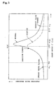
- Fig. 3 exemplifies an internal pressure profile as measured by an internal pressure sensor for one cycle in the combustion engine.
- the solid curve indicates the profile for normal combustion timing
- the single-dotted curve indicates the profile for a misfire timing.
- the internal pressure measured profile assumes an asymmetric shape in which the peak position is shifted to a larger angle side than the crank angle (i.e., an ⁇ TDC) corresponding to the TDC.
- ⁇ TDC crank angle
- Japanese Patent Laid-Open Nos. 321752/1992 , 72448/1992 and 325755/1992 discloses a method for deciding a misfire by comparing the magnitudes of a before top dead center pressure integrated value S 1 obtained by integrating the internal pressure measured values for a constant integration period defined in the before top dead center period and an after top dead center pressure integrated value S 2 obtained by integrating the average pressure information for a constant integration period defined in the after top dead center period.
- the tendency of the entire internal pressure measured profile can be reflected in an average form on the decision result so that a more accurate misfire decision can be made.
- the method using the gasket type pressure sensor indirectly measures the internal pressure, in that the fastening force of the spark plug fixing the sensor is loosened by the internal pressure.
- the absolute value of the measured pressure value As compared with the method of measuring the internal pressure directly through the pressure conduit by using the partition type sensor, therefore, there are a number of factors causing the absolute value of the measured pressure value to fluctuate. More specifically, variations in the force for fastening the spark plug and in the performance of individual piezoelectric elements easily cause the measured value level of the internal pressure to fluctuate, such that the measured value and its integrated value vary for a given internal pressure, easily resulting in an erroneous decision. In the above-specified patent publications, however, there is no disclosure of any specific means for reducing the adverse influences of these variation-causing factors.
- the invention provides a misfire deciding method for an internal combustion engine, characterized by:
- the invention provides a misfire deciding system for an internal combustion engine, comprising:
- the internal pressure measured profile for a constant period before and after the top dead center is determined so that the misfire decision may be made on the basis of the difference between the before top dead center pressure integrated value S 1 and the after top dead center pressure integrated value S 2 , as obtained for the before top dead center period and for the after top dead center period, respectively, that is, the differential integrated value ⁇ S ⁇ (S 2 - S 1 ).
- the method of making the misfire decision on the basis of the differential integrated value ⁇ S is convenient and is advantageous for easily canceling the influence of thermally caused drifts of the internal pressure measured values as described below. In either event, however, the misfire decision using the gasket type pressure sensor is easily caused to exert influences on the internal pressure measured value level due to variation in the fastening force of the sensor by the spark plug or in the performance of the piezoelectric element.
- the correction measurement point is set for the before top dead center period, and the first correction reference value is calculated using the internal pressure measured value at the correction measurement point, to correct the differential integrated value ⁇ S with the first correction reference value, to thereby make the misfire decision on the basis of the corrected differential integrated value ⁇ S.
- the correction measurement point set within the before top dead center period is relatively hardly influenced by the pressure rise due to the ignition/explosion of the fuel so that the internal pressure measured value obtained at the measurement point can be used as the reference value.
- the air-fuel ratio or the fuel consumption rate are substantially constant. If the crank angle at the correction measurement point is known, therefore, the internal pressure can be estimated from the volume of the combustion chamber at the correction measurement point. If the internal pressure measured value with the gasket type pressure sensor is corrected to match the estimated value of the internal pressure, therefore, the internal pressure measured value can be standardized even with variation in the sensor fastening force and in the piezoelectric element performance.
- the absolute value of the internal pressure is difficult to estimate even if the correction measurement point is set at the common crank angle position. According to the following method, however, the correction to standardize the internal pressure measured value can be rationally made without such an absolute value estimation.
- a first correction reference value is calculated as a difference of ⁇ P 0 ⁇ P 2 - P 1 between the internal pressure measured values P 1 and P 2 obtained for those two correction measurement points.
- the volumetric change in the gas between the two correction measurement points always takes a determined value, and the difference ⁇ P 0 has a meaning as the reference pressure change corresponding to the constant volumetric change.
- the measured value of the difference ⁇ P 0 fluctuates with the aforementioned dispersions in the fastening forces or the piezoelectric element performances, and the internal pressure measured value to be used for the misfire decision also fluctuates with the same tendency. If the internal pressure measured value is displayed by correcting it with a relative value calculated by dividing it by the difference ⁇ P 0 for the reference pressure change, therefore, the influences of the aforementioned dispersions can be effectively reduced not through the absolute value correction of the internal pressure.
- the value of (S 1 - S 2 )/ ⁇ P 0 calculated by the division with the difference ⁇ P 0 of the internal pressure measured value or the first correction reference value is calculated (Formula (1) of Fig. 4 ) as a decision index ⁇ , and the misfire decision is made on the basis of the decision index ⁇ . Then, the misfire decision using the value ⁇ S can be made more accurately and reproducibly.
- the internal pressure P is measured as a function of time or crank angle.
- the internal pressure is measured as a function P( ⁇ ) of the crank angle ⁇ .
- the values S 1 and S 2 can be calculated on the basis of Formulas (2) and (3) of Fig. 4 .
- the values S 1 and S 2 are calculated by numerical integrations by sampling the internal pressure measured value P at every minute angles ⁇ while monitoring the crank angle ⁇ by a crank angle sensor or the like.
- the integration variable should not be limited to the crank angle ⁇ but can be exemplified by the time t in a more convenient method.
- it is then effective to average and use the time-integrated value of the internal pressure measured value P by the measured value of the prevailing engine speed.
- the integrated value of the internal pressure measured value P conceptionally includes not only the mathematically integral value (Formulas (2) and (3) of Fig. 4 , as will be called the "mathematically integrated value") by the integral variable when the value P is expressed as a function of the crank angle ⁇ (or another parameter (e.g., the time t) which can correspond one to one to the value ⁇ ) as the integral variable but also another operation value, if this value reflects the integrated value.
- the sampling interval of the internal pressure measured value is constant, for example, the added value of the sampled internal pressure measured values for a constant period is the operation value reflecting the mathematically integrated value so that it can be adopted as the integrated value, as defined herein.
- the value calculated by dividing the mathematically integrated value or the added value by the width of the integration period or the number of added data expresses the average value of the internal pressure measured values for the individual periods and can be adopted as the integrated value, as defined herein.
- the differential integrated value ⁇ S is zero at the misfire. It is, therefore, theoretically possible to decide the combustion to be a misfire, if the value ⁇ S is zero, and to be normal if larger than zero. In the practical situations, however, due to various error factors (e.g., the influences due to the later-described hysteresis), the value ⁇ S does not become zero but is measured as a finite value even at the misfire. In this case, more or less of a margin is introduced into the decision reference for the value ⁇ S considering that error. In case the value ⁇ S becomes smaller than a positive lower limit, it is effective for avoiding the erroneous decision to decide the misfire.
- various error factors e.g., the influences due to the later-described hysteresis
- the integration period of the before top dead center period is set so longer as to correspond to the aforementioned margin of the decision reference. Then, it is also possible to decide the misfire, if the value ⁇ S takes zero or a negative value, and the normal combustion if larger than zero. In this case, strictly speaking, the integration period of the before top dead center period and the integration period of the after top dead center period are not equal.
- the gasket type pressure sensor used for the internal pressure measurement has a sensor element comprising piezoelectric ceramics.
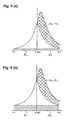
- the pressure sensor element using the piezoelectric ceramics has a problem that the zero point of the sensor output is liable to drift when the temperature changes.
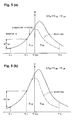
- Fig. 6(a) schematically illustrates the internal pressure measured profile in a steady state (at a low temperature), and Fig.
- FIG. 6(b) schematically illustrates the internal pressure measured profile in a transient state (at a high temperature).
- the internal pressure measured profiles are evenly shifted over the entire measurement period, if the period is so short as to cause no problem in the temperature change. If the integration periods are equally set for the before top dead center period and the after top dead center period, therefore, the influences of the zero-point drifts can be offset at the operation of ⁇ S ⁇ S 2 - S 1 , so that the misfire decision can be made more accurately.
- the difference of the value ⁇ S between the normal combustion time and the misfire time is as large as possible. From this viewpoint, it is effective that the ending point of the integration period set for the before top dead center period and the starting point of the integration period set for the after top dead center period are individually made identical to a top dead center ⁇ TDC, as illustrated in Fig. 4 .
- a second correction reference value is calculated on the basis of the internal pressure measured value of the combustion cycle (or the estimated misfire cycle) estimated in advance to be the misfire cycle, to correct the differential integrated value ⁇ S with the second correction reference value.
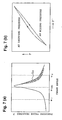
- Fig. 7(a) illustrates the results (in a solid curve) of the internal pressure measured value profile measured by the gasket type pressure sensor at the normal combustion time, in comparison with the results (in a broken curve) measured by a partition type standard pressure sensor through a pressure conduit formed in the cylinder head. It is thought that the measured values per se indicate the values more approximately from the true internal pressure. In the measurements by the gasket type pressure sensor, it is found that the profile at the pressure dropping time appears to shift to the higher pressure side than the profile at the pressure rising time. For example, Fig.
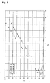
- Fig. 9 plots the decision index ⁇ obtained using two gasket type pressure sensors of common specifications, against a decision index ⁇ 0 obtained by the standard sensor. By adopting the decision index ⁇ , the two linear curves have substantially equal gradients.
- the frequency of occurrence of the hysteresis cannot be generally estimated unless the aforementioned standard sensor is used. Only at the misfire time, however, that frequency can be determined directly from the internal pressure measured value without providing the standard sensor.
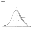
- the internal pressure measured value profile at the misfire time should theoretically be symmetric with respect to the top dead center position, as indicated by a broken curve in Fig. 8 .
- the profile at the pressure dropping time is raised to the extent of the hysteresis, although the misfire occurs without the hysteresis.
- the rising extent of the internal pressure measured value is calculated as the second correction reference value on the basis of the internal pressure measured value of the combustion cycle (or the estimated misfire cycle) which has been found in advance to become the misfire cycle.
- the misfire decision unit In order to estimate the rising extent of the internal pressure measured value accurately, it is necessary to use the internal pressure measured value in the cycle which has been fixed for that at the misfire time, i.e., in an estimated misfire cycle. This internal pressure measured value ordinarily never fails to occur at the fuel cutting time for an abrupt deceleration while the internal combustion engine for an automobile is running.
- the misfire decision unit is commonly used for an ECU (Electronic Control Unit) for controlling the ignition timing or the air/fuel ratio of the internal combustion engine, for example, or in case the misfire decision unit can acquire its control information from the ECU although not used for the ECU, therefore, the misfire decision unit can grasp the occurrence of the estimated misfire cycle reliably and can calculate the second correction reference value without any problem.
- ECU Electronic Control Unit
- the second correction reference value can be calculated as a value reflecting the differential integrated value S h in the estimated misfire cycle.
- the correction may be done by subtracting the value S h or the second correction reference value from the value S 2 of the value ⁇ S.
- the second correction reference value can use the decision index ⁇ obtained in the estimated misfire cycle, as a correction value ⁇ hp , and the decision index ⁇ obtained in the combustion cycle other than the estimated misfire cycle can be corrected, in a manner to subtract the correction value ⁇ hp . In either case, it is possible to make the accurate misfire decision, in which the influences of the hysteresis are lightened.
- the second correction reference value can be also calculated on the basis of the internal pressure measured value in a plurality of estimated misfire cycles having occurred in the past. For example, when the increment of the internal pressure measured value due to the hysteresis is expected to be varied with the time due to the occurring timing of the estimated misfire cycle, a more reliable value of the second correction reference value can be attained by further including a statistical process such as averaging the internal pressure measured values of a plurality of the estimated misfire cycles having occurred in the past.
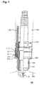
- Fig. 1 shows one example of the mounting mode of a gasket type pressure sensor.
- a spark plug 50 has a fastened thread portion 52 formed in the outer circumference of the leading end portion of a main fixture 51.
- the spark plug 50 is so fastened in a thread TH formed in the bottom of a plug hole PH, by fastening the fastened thread portion 52 into the thread TH so that a spark discharge gap g may be positioned in a combustion chamber ER with respect to a cylinder head SH of an internal combustion engine configured as an automobile engine.
- a flanged mounting seat 51f is formed to protrude from the outer circumference of the main fixture 51 at a position adjoining the base end portion of the fastened thread portion 52.
- a gasket type pressure sensor 5 has a ring-shaped sensor element 10 made of piezoelectric ceramics, which is clamped together with a ring-shaped gasket GS under a constant bias pressure in the axial directions between the mounting seat portion 51f and an open peripheral edge portion MP of the thread TH.
- the spark plug 50 receives the pressure in the axial directions so that the bias pressure applied to the sensor element 10 changes. As a result, the generation of piezoelectric charges in the sensor element 10 changes so that a correspondingly varying signal is extracted as a measured internal cylinder value P through an output cable CB.
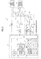
- Fig. 2 is a block diagram showing one example of a misfire decision unit in accordance with the invention using the gasket type pressure sensor 5.
- a misfire decision unit 1 has a main construction of an ECU 2 comprising a computer and executes control over such drive parameters of an internal combustion engine as an ignition timing or an air/fuel ratio, together with the misfire decision.
- the construction and functions of the ECU 2 are well known in the art excepting the misfire deciding function to be described hereinafter, and the following description will be focused on that misfire deciding function.
- the ECU 2 is constructed as a computer in which a CPU 3, a ROM 4, a RAM 5 and an input/output interface 6 are interconnected through a bus.
- the ROM 4 stores a control program defining the control processing functions of the ECU 2 and having a misfire decision routine incorporated therein.
- the CPU 3 realizes the function of the ECU 2 by executing the control program using the RAM 5 as a work memory.
- a crank angle sensor 7 for detecting the crank angle of the internal combustion engine is connected to the input/output interface 6.
- the crank angle sensor 7 is, for example, a pulse generator for detecting the rotational angle of the crankshaft.
- the pulse signal of the pulse generator is inputted to a predetermined port of the input/output interface 6 via a Schmitt trigger 8.
- the speed of the engine and the duration of one cycle can be monitored in real time with the interval of input pulses coming from the crank angle sensor 7.
- the pressure sensor element 10 is connected with the input/output interface 6 through a charge amplifier circuit 11.
- the output cable from the pressure sensor element 10 is connected with a negative input terminal of an operation amplifier 15, the positive input terminal of which is grounded (thereby forming an inverted amplifier using ground level as a reference voltage).
- the pressure sensor element 10 ( Fig. 2 ) generates a charge.
- a negative feedback capacitor 13 connected with the operation amplifier 15 stores a charge balancing that generated charge, and its terminal voltage is inputted as a voltage-transformed charge signal to the negative input terminal of the operation amplifier 15.
- the operation amplifier 15 forms a charge voltage transforming circuit together with the negative feedback capacitor 13 so as to output the charge developed in the pressure sensor element 10 as an amplified voltage signal.
- a resistor 12 connected in parallel with the negative feedback capacitor 13 promotes the discharge of the negative feedback capacitor 13, when the generated charge level of the pressure sensor element 10 turns negative, and prevents output saturation of the operation amplifier 15.
- a resistor 14 on the signal line from the pressure sensor element 10 protects the terminals of the operation amplifier 15.
- the output of the charge amplifier circuit 11 is inputted as an internal pressure measured value signal through a voltage follower 16 and an A/D converter 17 to a predetermined port of the input/output interface 6.
- a before top dead center pressure integrated value S 1 and an after top dead center pressure integrated value S 2 are calculated on the basis of the internal pressure measured value signal, as shown in Fig. 4 , and are used to make the misfire decision. Therefore, the output of the charge amplifier circuit 11 is branched and inputted to an integration circuit 24.
- the branched output of the charge amplifier circuit 11 is inputted through a voltage follower circuit 18 to an operation amplifier 19 forming a well-known integrator, with which a resistor 21 and a negative feedback capacitor 20 are connected.
- the integrated output of the integration circuit 24 is inputted to a predetermined port of the input/output interface 6 through an A/D converter 23.
- a switch circuit (as exemplified by a photo-MOS relay) 22 is connected with the negative feedback capacitor 20 for earthing/discharging the negative feedback capacitor 20 in response to an action command signal from the ECU 2.
- the integration circuit 24 integrates the output of the charge amplifier circuit 11, i.e., the internal pressure measured value P with time t. Strictly speaking, therefore, this value is not the integrated value which is expressed by the angle ⁇ of Formulae (2) and (3) of Fig. 4 .
- the prevailing engine speed i.e., the duration of one cycle (which may be an average value of a predetermined number of immediately preceding cycles, for example) can be calculated in real time. Therefore, the time-integrated value obtained can be transformed into the integrated value by the angle ⁇ , if it is divided by the duration of one cycle.
- the aforementioned time-integrated value can be used as it is, if the influence of the engine speed fluctuations at the misfire measuring time is low.
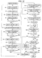
- the routine is initialized by resetting the ⁇ -counter and by activating the switching circuit 22 of Fig. 2 to reset the integrated output of the integrator. After these resets, the addition of the ⁇ -counter at S2 is started according to the execution of the cycle starting job by the ECU 2.
- the addition of the ⁇ -counter is continued on standby until the arrival of the sampling timing of the predetermined internal pressure measured value P and its integrated value S.
- the routine is on standby at S3 for reading the input ports of the internal pressure measured signal and its integrated value, and the ⁇ -counter is read at S4.
- the routine is judged whether or not the crank angle ⁇ indicated by the ⁇ -counter has reached a starting point ⁇ 1 (or a point for setting a first one of the aforementioned two correction measurement points in this embodiment) of the before top dead center integration period set to a period after an intake valve is closed. If this answer is NO, the routine returns to S3 to repeat the subsequent operations. If YES, the routine advances to the operations at and after S6.
- the internal pressure measured value P is read in response to the arrival of the first correction measurement point and is set as the aforementioned value P 1 in the memory. Moreover, the switching circuit 22 is turned off to release the integrator from the reset state at S7. As a result, the integration of the internal pressure measured value P is started at and after the starting point ⁇ 1. Then, the standby is restored again for sampling at S8, and it is judged at S9 whether or not the value ⁇ has reached the second one of the two correction measurement points. If the answer is NO, the routine returns to S8, at which the subsequent operations are repeated. If YES, the routine advances to the operations at and after S10.
- the internal pressure measured value P is read in response to the arrival of the second correction measurement point and is set as the aforementioned value P 2 in the memory.
- the standby is made for the sampling.
- the input value from the integrator is read. This value indicates the before top dead center pressure integrated value S 1 (of Formula (2) of Fig. 4 ) and is set as the value S 1 in the memory.
- the input value from the integrator is the time-integrated value of the value P as described above.
- the duration T of one cycle is determined from the input pulse interval from the crank angle sensor 7, and the crank angle ⁇ is transformed into the integrated value by dividing it with the duration T, although omitted from the flow chart.
- the standby is restored again for the sampling, and it is judged at S16 whether or not the value ⁇ has reached the ending point ⁇ 2 of the integration period of the after top dead center pressure integrated value S2. If the answer is NO, the routine returns to S15, and the subsequent operations are repeated. If YES, the routine advances to operations at and after S17.
- the input value of the integrator is read again according to the arrival of the ending point ⁇ 2.
- the value S 2 is calculated as the value of S p - S 1 .
- the routine advances to S19, at which the value of the aforementioned decision index ⁇ is calculated by using the calculated values S 1 , S 2 and ⁇ P 0 .
- a correction value ⁇ hp for the aforementioned hysteresis correction which has been calculated and stored in the preceding routine.
- a correction is made to calculate the final corrected decision index ⁇ ' by subtracting the correction value ⁇ hp from the decision index ⁇ already obtained.
- this value ⁇ ' is compared with a decision reference value (or an upper limit value) ⁇ c , and the decision of misfire is made if ⁇ ' ⁇ ⁇ c .
- the ECU 2 of Fig. 2 outputs a predetermined misfire decision ( Fig. 10 : S23) from a decision output port of the input/output interface 6.
- this cycle is an estimated misfire cycle such as a fuel cut cycle intended from the beginning by the ECU 2, the routine advances to S25 in Fig. 10 .
- the correction value ⁇ hp is updated by using the decision index ⁇ before the correction, which has been obtained in that cycle.
- Fig. 11 shows the updating method schematically.
- the differential integrated value is used as a correction value so that it is expressed by ⁇ S h and is further suffixed into ⁇ S h1 , ⁇ S h2 , ---, and ⁇ S hk so as to correspond to the time series array of the estimated misfire cycle.
- the differential integrated value is calculated as an average value ⁇ S hm of the values ⁇ S h which are obtained in a plurality of (e.g., an N-number of) preceding estimated misfire cycles, as indicated by [1] in Fig. 11 .
- the value ⁇ S h obtained in an estimated misfire cycle may take such a numerical value as extraordinarily deviates from the tendency of the preceding ⁇ S h . Therefore, the following method can be adopted as one for obtaining the corrected value ⁇ hp of a higher reliability by reducing the influence of the extraordinary value.
- the product value of the average value ⁇ S hm of the values ⁇ S h of the just preceding N-number and the term ⁇ /(1 - ⁇ ) by using a correction coefficient ⁇ is used as a predicted value ⁇ Shp of a next value ⁇ Shi, as indicated by [2] in Fig. 11 .
- a correction factor A i is calculated for each estimated misfire cycle from a Formula [3] of Fig. 11 .
- the aforementioned correction coefficient ⁇ is calculated as an average value of the correction factors A i which have already been obtained in the just preceding N-number of estimated misfire cycles, by Formula [4] of Fig. 11 .
- the value A is so clarified, if modified into [3]' by dividing the denominator and numerator of Formula [3] individually by ⁇ S hi , as to come closer to 1/2 if the difference between the result value ( ⁇ S hi ) and the predicted value ( ⁇ S hp ) relating to the value ⁇ S h becomes smaller, to 1 if the result value becomes larger from the predicted value, and to 0 if smaller on the contrary.
- the correction coefficient ⁇ or the average value of the values A i also becomes closer to 1/2 (as will be termed into the "pattern 1") as the number of cycles of smaller difference between the result value and the predicted value becomes larger in the product of ⁇ S h in the past estimated misfire cycles, to 1 (as will be termed into the “pattern 2”) as the number of cycles, in which the result value is far higher than the predicted value, becomes larger, and to 0 (as will be termed into the "pattern 3”) as the number of cycles, in which the result value is far lower on the contrary, becomes larger.
- the value of ⁇ /(1 - ⁇ ) approaches closer to 1 in the pattern 1.
- the difference between the result value and the predicted value is intrinsically small so that the effect of correction can be reduced.
- the value of ⁇ /(1 - ⁇ ) is inversely higher as the difference of the result value from the predicted value is larger. Therefore, the predicted value becomes higher toward the result value so that the correction precision is enhanced.
- the value of ⁇ /(1 - ⁇ ) approaches closer to 0 as the difference of the result value from the predicted value becomes larger. In other words, the predicted value becomes smaller toward the result value so that the correction accuracy is likewise enhanced.
- each value ⁇ S h can be transformed into the value ⁇ hp by dividing it by the corresponding value ⁇ P 0 .
- a correction factor A using the ⁇ and the correction coefficient ⁇ can be likewise calculated by replacing the value ⁇ S h by the value ⁇ hp in Formulae [3] and [4] of Fig. 11 .
- the aforementioned integrations can be made by a software in the ECU 2, and the integration circuit 24 of Fig. 2 can then be omitted. It is also easily realized by processing a program to acquire the integrated value with the angle ⁇ by using the input pulse interval from the crank angle sensor 7.
- the measuring job includes two steps of reading (U1) the internal pressure measured value P and setting (U2) a measurement end flag indicating that the reading(or measurement) of the value P has completed.
- the routine advances to T5, at which the prevailing crank angle ⁇ is read. If this angle ⁇ is smaller than the value ⁇ TDC, the routine advances to T6, at which the value P is added to the integration memory of S1. Moreover, it is confirmed at T7 whether or not the value ⁇ has reached ⁇ 1.
- the routine advances to T8, at which the prevailing value P is stored as the aforementioned value P 1 .
- the measurement end flag is reset, and the routine is returned to T4. After this, these operations are repeated.
- the routine advances to T10, at which it is judged whether or not the aforementioned value ⁇ J has been reached. If this answer is YES, the routine advances to T11, at which the prevailing value P is stored as the aforementioned P 2 and at which the value ⁇ P 0 is calculated and stored as P 2 -P 1 , (otherwise the routine skips T11). After this, at T9, the measurement end flag is reset, and the routine is returned to T4 to repeat the subsequent operations.
- the routine advances to T12. If it is judged at T12 that the value ⁇ is equal to ⁇ TDC, the routine advances to T13. At T13, the final addition of P to S 1 is made, and the addition of P to S 2 is started. The routine is returned through T9 to T4. This is because the value P at ⁇ TDC belongs to both S 1 and S 2 . If the value ⁇ is sufficiently small, the operation can be done assuming that the value P at ⁇ TDC belongs to either S 1 or S 2 .
- the routine advances to T14, at which it is judged that the value ⁇ is no more than ⁇ 2. If this answer is YES, the routine advances to T15, at which the addition of P to S 2 is continued. If NO, on the other hand, the routine advances to T16, at which the interruption of the measuring job is inhibited (that is, the interruption terminal is masked) to end the integrating operations and to advance to T17.
- T17 the interruption of the measuring job is inhibited (that is, the interruption terminal is masked) to end the integrating operations and to advance to T17.
- the operations at and after T17 will be omitted on their description, because they are similar to those at and after S19 of Fig. 10 .
- Fig. 12 plots the results of misfire decisions based on the value of the aforementioned differential integral value ⁇ S.
- Solid diamonds plot the average values of ⁇ S of the cycle decided as a normal combustion, together with their distribution ranges (as indicated by error bars).
- the solid squares plot the average values of ⁇ S of the cycle decided as a misfire, together with their dispersion ranges.
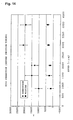
- Fig. 13 plots similar experimental results of the case in which the misfire decision is made by using the aforementioned decision index ⁇ .
- the first correction measuring point was set at the integration period starting point ⁇ 1 and at a BTDC of 90 degrees
- the second correction measuring point was set at BTDC of 5 degrees after the ignition timing. It is seen, as compared with Fig.
- Fig. 14 plots the case in which the second correction measuring point was set at a BTDC of 20 degrees before the ignition timing, and imdicates that the dispersion range ratio in the low speed range was further reduced.
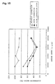
- Fig. 15 summarizes the dispersion range ratios to the average value at every speed for the foregoing three results. It is apparent that the setting of the second correction measuring point before the ignition timing gave the most excellent result.
- Fig. 16(a) shows an example, in which the differential integration values ⁇ S obtained by using the gasket type pressure sensor are plotted against the differential integration values ⁇ S 0 obtained by using the standard sensor. Both the sensors caused generally linear changes of ⁇ S against ⁇ S 0 but a large difference in the values of the gradient and the intercept.
- Fig. 16(b) plots the decision indexes ⁇ , which were obtained by dividing the differential integration values of the two sensors by the value ⁇ P 0 , against the similar decision indexes ⁇ 0 which were obtained by using the standard sensor. It is found that the difference in the gradient between the two straight lines was remarkably reduced.
- Fig. 16(b) shows an example, in which the differential integration values ⁇ S obtained by using the gasket type pressure sensor are plotted against the differential integration values ⁇ S 0 obtained by using the standard sensor. Both the sensors caused generally linear changes of ⁇ S against ⁇ S 0 but a large difference in the values of the gradient and the intercept.
Landscapes
- Engineering & Computer Science (AREA)
- Chemical & Material Sciences (AREA)
- Combustion & Propulsion (AREA)
- Physics & Mathematics (AREA)
- General Physics & Mathematics (AREA)
- Mechanical Engineering (AREA)
- General Engineering & Computer Science (AREA)
- Combined Controls Of Internal Combustion Engines (AREA)
- Measuring Fluid Pressure (AREA)
- Testing Of Engines (AREA)
- Ignition Installations For Internal Combustion Engines (AREA)
Claims (11)
- Procédé pour décider de la présence de ratés d'allumage dans un moteur à combustion interne, comprenant des étapes consistant à :acquérir une valeur mesurée de pression interne à partir de la pression interne d'un moteur à combustion interne, auquel est fixée une bougie d'allumage, fournie par un capteur de pression monté dans un siège de montage de ladite bougie d'allumage ;calculer la valeur intégrée desdites valeurs mesurées de pression interne pour une première période d'intégration constante après la fermeture d'une soupape d'admission et avant qu'une position de vilebrequin n'atteigne le point mort haut, et établir la valeur calculée à une valeur intégrée S1 avant le point mort haut ;calculer la valeur intégrée desdites valeurs mesurées de pression interne pour une seconde période d'intégration constante après que ladite position de vilebrequin a atteint le point mort haut et avant l'ouverture d'une soupape d'admission, et établir la valeur calculée à une valeur intégrée S2 après le point mort haut ;calculer une valeur différentielle intégrée S1 - S2 entre ladite valeur intégrée S2 après le point mort haut et ladite valeur calculée à une valeur intégrée S1 avant le point mort haut ;calculer une première valeur de référence de correction à l'aide de la valeur mesurée de pression interne à un instant de mesure de correction établi pour ladite première période d'intégration, afin de corriger ladite valeur différentielle intégrée avec ladite première valeur de référence de correction, etprendre une décision quant à la présence de ratés d'allumage d'après la valeur différentielle intégrée corrigée.
- Procédé pour décider de la présence de ratés d'allumage dans un moteur à combustion interne selon la revendication 1, comprenant une étape consistant à établir lesdites première et seconde périodes d'intégration à une durée égale.
- Procédé pour décider de la présence de ratés d'allumage dans un moteur à combustion interne selon la revendication 1 ou 2, comprenant une étape consistant à établir l'instant final de ladite première période d'intégration et l'instant initial de ladite seconde période d'intégration au point mort haut.
- Procédé pour décider de la présence de ratés d'allumage dans un moteur à combustion interne selon l'une quelconque des revendications 1 à 3, comprenant une étape consistant à établir ledit instant de mesure de correction avant le calage de l'allumage pour la première période d'intégration.
- Procédé pour décider de la présence de ratés d'allumage dans un moteur à combustion interne selon l'une quelconque des revendications 1 à 4, comprenant une étape consistant à établir deux instants différents pour ledit instant de mesure de correction afin de calculer ladite première valeur de référence de correction comme différence ΔP0 entre des valeurs mesurées de pression interne obtenues auxdits deux instants de mesure de correction.
- Procédé pour décider de la présence de ratés d'allumage dans un moteur à combustion interne selon la revendication 5, comprenant des étapes consistant à calculer la valeur de (S1 - S2)/ΔP0 calculée en divisant ladite valeur différentielle intégrée de S1- S2 par la différence ΔP0 de ladite valeur mesurée de pression interne ou ladite première valeur de référence de correction en tant qu'indice de décision λ, et à prendre ladite décision quant à la présence de ratés d'allumage d'après ledit indice de décision λ.
- Procédé pour décider de la présence de ratés d'allumage dans un moteur à combustion interne selon l'une quelconque des revendications 1 à 6, comprenant une étape consistant à calculer une seconde valeur de référence de correction d'après ladite valeur mesurée de pression interne d'un cycle de combustion estimé à l'avance comme étant un cycle à ratés d'allumage, et corriger ladite valeur différentielle intégrée avec ladite seconde valeur de référence de correction.
- Procédé pour décider de la présence de ratés d'allumage dans un moteur à combustion interne selon la revendication 7, comprenant une étape consistant à calculer ladite seconde valeur de préférence de correction en tant que valeur reflétant ladite valeur différentielle intégrée dans ledit cycle à ratés d'allumage estimés.
- Procédé pour décider de la présence de ratés d'allumage dans un moteur à combustion interne selon la revendication 8, comprenant des étapes consistant à utiliser ledit indice de décision λ obtenu lors dudit cycle à ratés d'allumage estimés, en tant que valeur de correction λhp pour ladite seconde valeur de référence de correction, et corriger ledit indice de décision λ obtenu, lors d'un cycle de combustion autre que ledit cycle à ratés d'allumage estimés, en soustrayant ladite valeur de correction λhp.
- Procédé pour décider de la présence de ratés d'allumage dans un moteur à combustion interne selon l'une quelconque des revendications 7 à 9, comprenant une étape consistant à calculer ladite seconde valeur de référence de correction à partir de ladite valeur mesurée de pression interne lors d'une pluralité de cycles à ratés d'allumage estimés survenus précédemment.
- Système pour décider de la présence de ratés d'allumage dans un moteur à combustion interne, comprenant :un capteur de pression monté dans un siège de montage d'une bougie d'allumage pour acquérir une valeur mesurée de pression interne à partir de la pression interne d'un moteur à combustion interne dans lequel est montée la bougie d'allumage ; etun élément de prise de décision pour : calculer la valeur intégrée desdites valeurs mesurées de pression interne pour une première période d'intégration constante après la fermeture d'une soupape d'admission et avant qu'une position de vilebrequin n'atteigne le point mort haut, et établir la valeur calculée à une valeur intégrée S1 avant le point mort haut ; calculer la valeur intégrée desdites valeurs mesurées de pression interne pour une seconde période d'intégration constante après que ladite position de vilebrequin a atteint le point mort haut et avant l'ouverture d'une soupape d'admission, et établir la valeur calculée à une valeur intégrée S2 après le point mort haut ; calculer une valeur différentielle intégrée S1 - S2 entre ladite valeur intégrée S2 après le point mort haut et ladite valeur intégrée S1 avant le point mort haut ; calculer une première valeur de référence de correction à l'aide de la valeur mesurée de pression interne à un instant de mesure de correction établi pour ladite première période d'intégration, afin de corriger ladite valeur différentielle intégrée avec ladite première valeur de référence de correction, et prendre une décision quant à la présence de ratés d'allumage d'après la valeur différentielle intégrée corrigée.
Applications Claiming Priority (2)
| Application Number | Priority Date | Filing Date | Title |
|---|---|---|---|
| JP2001135613A JP2002332908A (ja) | 2001-05-02 | 2001-05-02 | 内燃機関の失火検出方法及び失火検出システム |
| JP2001135613 | 2001-05-02 |
Publications (3)
| Publication Number | Publication Date |
|---|---|
| EP1255100A2 EP1255100A2 (fr) | 2002-11-06 |
| EP1255100A3 EP1255100A3 (fr) | 2004-02-04 |
| EP1255100B1 true EP1255100B1 (fr) | 2010-04-21 |
Family
ID=18983043
Family Applications (1)
| Application Number | Title | Priority Date | Filing Date |
|---|---|---|---|
| EP02253097A Expired - Lifetime EP1255100B1 (fr) | 2001-05-02 | 2002-05-01 | Procédé et système pour décider sur la présence des ratés d'allumage dans des moteurs à combustion interne |
Country Status (4)
| Country | Link |
|---|---|
| US (1) | US6776032B2 (fr) |
| EP (1) | EP1255100B1 (fr) |
| JP (1) | JP2002332908A (fr) |
| DE (1) | DE60236044D1 (fr) |
Families Citing this family (16)
| Publication number | Priority date | Publication date | Assignee | Title |
|---|---|---|---|---|
| JP4815047B2 (ja) * | 2000-11-30 | 2011-11-16 | 日本特殊陶業株式会社 | 圧力センサユニット |
| US6679100B2 (en) * | 2001-03-05 | 2004-01-20 | Delphi Technologies, Inc. | Spark plug mounted thick film strain gauge |
| JP4094475B2 (ja) * | 2003-04-21 | 2008-06-04 | 富士重工業株式会社 | 多気筒エンジンの燃焼圧データ収集システム |
| JP4571481B2 (ja) * | 2004-11-29 | 2010-10-27 | 富士重工業株式会社 | バルブクリアランス評価用データベース作成方法 |
| JP4509986B2 (ja) * | 2005-12-27 | 2010-07-21 | 本田技研工業株式会社 | 内燃機関の失火検出装置 |
| JP4630842B2 (ja) * | 2006-05-09 | 2011-02-09 | 本田技研工業株式会社 | 内燃機関の筒内圧検出装置 |
| US7907303B2 (en) * | 2006-06-30 | 2011-03-15 | Konica Minolta Systems Laboratory, Inc. | Systems and methods for processing pixel data for a printer |
| JP2009214688A (ja) * | 2008-03-10 | 2009-09-24 | Toyota Motor Corp | 筒内圧検出装置の出力補正装置 |
| JP4870793B2 (ja) * | 2009-05-07 | 2012-02-08 | 本田技研工業株式会社 | 内燃機関の図示平均有効圧を計測する装置 |
| EP2375038B1 (fr) * | 2010-04-08 | 2015-03-04 | Delphi International Operations Luxembourg S.à r.l. | Dispositif et procédé de diagnostic utilisant un capteur de pression dans un cylindre pour moteur à combustion interne |
| US9279406B2 (en) | 2012-06-22 | 2016-03-08 | Illinois Tool Works, Inc. | System and method for analyzing carbon build up in an engine |
| JP6060006B2 (ja) * | 2013-02-22 | 2017-01-11 | 本田技研工業株式会社 | 燃料噴射制御装置 |
| DE102013017754A1 (de) * | 2013-10-24 | 2015-04-30 | GM Global Technology Operations LLC (n. d. Gesetzen des Staates Delaware) | Steuermittel und Verfahren zum Betreiben einer Brennkraftmaschine |
| JP6052325B2 (ja) * | 2014-06-27 | 2016-12-27 | トヨタ自動車株式会社 | 内燃機関システム |
| JP6137705B2 (ja) * | 2015-02-02 | 2017-05-31 | 株式会社Subaru | 失火判定装置 |
| US9631566B1 (en) * | 2015-10-27 | 2017-04-25 | Caterpillar Inc. | Pre-chamber fuel admission valve diagnostics |
Family Cites Families (19)
| Publication number | Priority date | Publication date | Assignee | Title |
|---|---|---|---|---|
| JPS59206648A (ja) * | 1983-01-26 | 1984-11-22 | Nissan Motor Co Ltd | 内燃機関の燃焼室内圧力を検出するセンサの較正方法 |
| US5076098A (en) * | 1990-02-21 | 1991-12-31 | Nissan Motor Company, Limited | System for detecting combustion state in internal combustion engine |
| JP2611502B2 (ja) | 1990-06-13 | 1997-05-21 | 三菱電機株式会社 | 内燃機関の失火検出装置 |
| JPH0472448A (ja) | 1990-07-11 | 1992-03-06 | Ngk Spark Plug Co Ltd | 内燃機関用失火検出装置 |
| DE4126782C2 (de) * | 1990-08-13 | 2001-02-15 | Mitsubishi Electric Corp | Gerät und Verfahren zur Erfassung von Fehlzündungen bei einem Verbrennungsmotor |
| JP2946126B2 (ja) | 1991-04-19 | 1999-09-06 | 日本特殊陶業株式会社 | 内燃機関の燃焼状態監視装置 |
| JP3087855B2 (ja) | 1991-04-24 | 2000-09-11 | 日本特殊陶業株式会社 | 内燃機関用失火検出装置 |
| US5309756A (en) * | 1991-07-04 | 1994-05-10 | Toyota Jidosha Kabushiki Kaisha | Device for determining malfunction of an engine cylinder |
| JP2606019B2 (ja) * | 1991-09-18 | 1997-04-30 | 三菱電機株式会社 | 内燃機関の失火検出装置 |
| JP2753412B2 (ja) * | 1992-02-04 | 1998-05-20 | 三菱電機株式会社 | 内燃機関失火判定装置 |
| US5305635A (en) * | 1993-04-02 | 1994-04-26 | Ford Motor Company | System and method for filtering a misfire detecting data stream to yield optimum measurement of misfire rate |
| JPH07259631A (ja) * | 1994-03-18 | 1995-10-09 | Mitsubishi Electric Corp | 内燃機関の失火検出装置 |
| JP3294957B2 (ja) * | 1994-10-26 | 2002-06-24 | 本田技研工業株式会社 | 内燃機関の制御装置 |
| US5529041A (en) * | 1995-05-09 | 1996-06-25 | Cummins Engine Company, Inc. | Active engine misfire detection system |
| US5845492A (en) * | 1995-09-18 | 1998-12-08 | Nippondenso Co., Ltd. | Internal combustion engine control with fast exhaust catalyst warm-up |
| JPH09209814A (ja) * | 1996-02-05 | 1997-08-12 | Unisia Jecs Corp | 内燃機関の制御装置 |
| US5775298A (en) * | 1996-12-09 | 1998-07-07 | General Motors Corporation | Internal combustion engine control |
| JP3855481B2 (ja) * | 1998-08-12 | 2006-12-13 | 株式会社日立製作所 | エンジンの診断装置 |
| US6371092B1 (en) * | 2001-01-10 | 2002-04-16 | Econtrols, Inc. | Fuel system with dual fuel injectors for internal combustion engines |
-
2001
- 2001-05-02 JP JP2001135613A patent/JP2002332908A/ja active Pending
-
2002
- 2002-05-01 EP EP02253097A patent/EP1255100B1/fr not_active Expired - Lifetime
- 2002-05-01 DE DE60236044T patent/DE60236044D1/de not_active Expired - Lifetime
- 2002-05-01 US US10/135,767 patent/US6776032B2/en not_active Expired - Fee Related
Also Published As
| Publication number | Publication date |
|---|---|
| JP2002332908A (ja) | 2002-11-22 |
| US6776032B2 (en) | 2004-08-17 |
| EP1255100A2 (fr) | 2002-11-06 |
| EP1255100A3 (fr) | 2004-02-04 |
| DE60236044D1 (de) | 2010-06-02 |
| US20020183919A1 (en) | 2002-12-05 |
Similar Documents
| Publication | Publication Date | Title |
|---|---|---|
| US6776032B2 (en) | Misfire deciding method and misfire deciding system for internal combustion engines | |
| US4819603A (en) | System and method for controlling ignition timing for an internal combustion engine | |
| EP1586882B1 (fr) | Appareil et procédé de détermination de cliquetis pour moteur à combustion interne | |
| US5307670A (en) | Misfire discriminating method for an engine | |
| KR100364455B1 (ko) | 내연기관의 노킹검출방법 | |
| EP0411580A1 (fr) | Système pour la détermination de pression dans le cylindre d'un moteur à combustion interne | |
| US4399802A (en) | Ignition energy control method and system | |
| JP3357091B2 (ja) | エンジンの失火検出方法 | |
| EP0115317A2 (fr) | Méthode de calibrage d'un détecteur de pression | |
| US5447061A (en) | Misfire detection method for engine | |
| US5373732A (en) | Combustion state-detecting system for internal combustion engines | |
| EP2871355B1 (fr) | Dispositif de commande de période d'allumage de moteur à combustion interne | |
| JP2536243B2 (ja) | 内燃機関の点火時期制御装置 | |
| US8005607B2 (en) | Device and method for controlling ignition timing of internal combustion engine | |
| JP4871779B2 (ja) | エンジン回転数制御装置 | |
| JPH01193065A (ja) | エンジンの制御装置 | |
| US4986245A (en) | Control system for internal combustion engine with improved transition characteristics | |
| JP4383693B2 (ja) | 内燃機関の失火検出方法及び失火検出システム | |
| EP0072162B1 (fr) | Méthode et système de commande d'avance à l'allumage pour un moteur à combustion interne à plusieurs cylindres | |
| JP2006284533A (ja) | 筒内圧力センサの異常検知装置 | |
| US4777919A (en) | Ignition timing control apparatus for an internal combustion engine | |
| CN115126615B (zh) | 数据处理方法 | |
| Hönig et al. | Electronic Spark Control Systems | |
| US6945230B2 (en) | Method for eliminating detonation in an engine | |
| JPH01106934A (ja) | 内燃機関の空燃比制御装置 |
Legal Events
| Date | Code | Title | Description |
|---|---|---|---|
| PUAI | Public reference made under article 153(3) epc to a published international application that has entered the european phase |
Free format text: ORIGINAL CODE: 0009012 |
|
| AK | Designated contracting states |
Kind code of ref document: A2 Designated state(s): AT BE CH CY DE DK ES FI FR GB GR IE IT LI LU MC NL PT SE TR |
|
| AX | Request for extension of the european patent |
Free format text: AL;LT;LV;MK;RO;SI |
|
| PUAL | Search report despatched |
Free format text: ORIGINAL CODE: 0009013 |
|
| AK | Designated contracting states |
Kind code of ref document: A3 Designated state(s): AT BE CH CY DE DK ES FI FR GB GR IE IT LI LU MC NL PT SE TR |
|
| AX | Request for extension of the european patent |
Extension state: AL LT LV MK RO SI |
|
| RIC1 | Information provided on ipc code assigned before grant |
Ipc: 7G 01M 5/00 A Ipc: 7G 01M 15/00 B |
|
| 17P | Request for examination filed |
Effective date: 20040804 |
|
| AKX | Designation fees paid |
Designated state(s): DE FR GB IT |
|
| GRAP | Despatch of communication of intention to grant a patent |
Free format text: ORIGINAL CODE: EPIDOSNIGR1 |
|
| GRAS | Grant fee paid |
Free format text: ORIGINAL CODE: EPIDOSNIGR3 |
|
| GRAA | (expected) grant |
Free format text: ORIGINAL CODE: 0009210 |
|
| AK | Designated contracting states |
Kind code of ref document: B1 Designated state(s): DE FR GB IT |
|
| REG | Reference to a national code |
Ref country code: GB Ref legal event code: FG4D |
|
| REF | Corresponds to: |
Ref document number: 60236044 Country of ref document: DE Date of ref document: 20100602 Kind code of ref document: P |
|
| PLBE | No opposition filed within time limit |
Free format text: ORIGINAL CODE: 0009261 |
|
| STAA | Information on the status of an ep patent application or granted ep patent |
Free format text: STATUS: NO OPPOSITION FILED WITHIN TIME LIMIT |
|
| GBPC | Gb: european patent ceased through non-payment of renewal fee |
Effective date: 20100721 |
|
| 26N | No opposition filed |
Effective date: 20110124 |
|
| PG25 | Lapsed in a contracting state [announced via postgrant information from national office to epo] |
Ref country code: IT Free format text: LAPSE BECAUSE OF FAILURE TO SUBMIT A TRANSLATION OF THE DESCRIPTION OR TO PAY THE FEE WITHIN THE PRESCRIBED TIME-LIMIT Effective date: 20100421 |
|
| PG25 | Lapsed in a contracting state [announced via postgrant information from national office to epo] |
Ref country code: GB Free format text: LAPSE BECAUSE OF NON-PAYMENT OF DUE FEES Effective date: 20100721 |
|
| REG | Reference to a national code |
Ref country code: FR Ref legal event code: PLFP Year of fee payment: 15 |
|
| REG | Reference to a national code |
Ref country code: FR Ref legal event code: PLFP Year of fee payment: 16 |
|
| PGFP | Annual fee paid to national office [announced via postgrant information from national office to epo] |
Ref country code: DE Payment date: 20170426 Year of fee payment: 16 Ref country code: FR Payment date: 20170413 Year of fee payment: 16 |
|
| REG | Reference to a national code |
Ref country code: DE Ref legal event code: R119 Ref document number: 60236044 Country of ref document: DE |
|
| PG25 | Lapsed in a contracting state [announced via postgrant information from national office to epo] |
Ref country code: DE Free format text: LAPSE BECAUSE OF NON-PAYMENT OF DUE FEES Effective date: 20181201 Ref country code: FR Free format text: LAPSE BECAUSE OF NON-PAYMENT OF DUE FEES Effective date: 20180531 |