EP1297773B1 - Rotationsbürstenanordnung und damit ausgerüsteter Staubsauger - Google Patents
Rotationsbürstenanordnung und damit ausgerüsteter Staubsauger Download PDFInfo
- Publication number
- EP1297773B1 EP1297773B1 EP02025302A EP02025302A EP1297773B1 EP 1297773 B1 EP1297773 B1 EP 1297773B1 EP 02025302 A EP02025302 A EP 02025302A EP 02025302 A EP02025302 A EP 02025302A EP 1297773 B1 EP1297773 B1 EP 1297773B1
- Authority
- EP
- European Patent Office
- Prior art keywords
- rotary brush
- opening
- sucking
- brush device
- cylindrical body
- Prior art date
- Legal status (The legal status is an assumption and is not a legal conclusion. Google has not performed a legal analysis and makes no representation as to the accuracy of the status listed.)
- Expired - Lifetime
Links
Images





Classifications
-
- A—HUMAN NECESSITIES
- A47—FURNITURE; DOMESTIC ARTICLES OR APPLIANCES; COFFEE MILLS; SPICE MILLS; SUCTION CLEANERS IN GENERAL
- A47L—DOMESTIC WASHING OR CLEANING; SUCTION CLEANERS IN GENERAL
- A47L9/00—Details or accessories of suction cleaners, e.g. mechanical means for controlling the suction or for effecting pulsating action; Storing devices specially adapted to suction cleaners or parts thereof; Carrying-vehicles specially adapted for suction cleaners
- A47L9/02—Nozzles
- A47L9/04—Nozzles with driven brushes or agitators
- A47L9/0405—Driving means for the brushes or agitators
- A47L9/0411—Driving means for the brushes or agitators driven by electric motor
-
- A—HUMAN NECESSITIES
- A47—FURNITURE; DOMESTIC ARTICLES OR APPLIANCES; COFFEE MILLS; SPICE MILLS; SUCTION CLEANERS IN GENERAL
- A47L—DOMESTIC WASHING OR CLEANING; SUCTION CLEANERS IN GENERAL
- A47L9/00—Details or accessories of suction cleaners, e.g. mechanical means for controlling the suction or for effecting pulsating action; Storing devices specially adapted to suction cleaners or parts thereof; Carrying-vehicles specially adapted for suction cleaners
- A47L9/02—Nozzles
- A47L9/04—Nozzles with driven brushes or agitators
-
- A—HUMAN NECESSITIES
- A47—FURNITURE; DOMESTIC ARTICLES OR APPLIANCES; COFFEE MILLS; SPICE MILLS; SUCTION CLEANERS IN GENERAL
- A47L—DOMESTIC WASHING OR CLEANING; SUCTION CLEANERS IN GENERAL
- A47L5/00—Structural features of suction cleaners
- A47L5/12—Structural features of suction cleaners with power-driven air-pumps or air-compressors, e.g. driven by motor vehicle engine vacuum
- A47L5/22—Structural features of suction cleaners with power-driven air-pumps or air-compressors, e.g. driven by motor vehicle engine vacuum with rotary fans
- A47L5/28—Suction cleaners with handles and nozzles fixed on the casings, e.g. wheeled suction cleaners with steering handle
-
- A—HUMAN NECESSITIES
- A47—FURNITURE; DOMESTIC ARTICLES OR APPLIANCES; COFFEE MILLS; SPICE MILLS; SUCTION CLEANERS IN GENERAL
- A47L—DOMESTIC WASHING OR CLEANING; SUCTION CLEANERS IN GENERAL
- A47L5/00—Structural features of suction cleaners
- A47L5/12—Structural features of suction cleaners with power-driven air-pumps or air-compressors, e.g. driven by motor vehicle engine vacuum
- A47L5/22—Structural features of suction cleaners with power-driven air-pumps or air-compressors, e.g. driven by motor vehicle engine vacuum with rotary fans
- A47L5/28—Suction cleaners with handles and nozzles fixed on the casings, e.g. wheeled suction cleaners with steering handle
- A47L5/30—Suction cleaners with handles and nozzles fixed on the casings, e.g. wheeled suction cleaners with steering handle with driven dust-loosening tools, e.g. rotating brushes
-
- A—HUMAN NECESSITIES
- A47—FURNITURE; DOMESTIC ARTICLES OR APPLIANCES; COFFEE MILLS; SPICE MILLS; SUCTION CLEANERS IN GENERAL
- A47L—DOMESTIC WASHING OR CLEANING; SUCTION CLEANERS IN GENERAL
- A47L9/00—Details or accessories of suction cleaners, e.g. mechanical means for controlling the suction or for effecting pulsating action; Storing devices specially adapted to suction cleaners or parts thereof; Carrying-vehicles specially adapted for suction cleaners
- A47L9/02—Nozzles
-
- A—HUMAN NECESSITIES
- A47—FURNITURE; DOMESTIC ARTICLES OR APPLIANCES; COFFEE MILLS; SPICE MILLS; SUCTION CLEANERS IN GENERAL
- A47L—DOMESTIC WASHING OR CLEANING; SUCTION CLEANERS IN GENERAL
- A47L9/00—Details or accessories of suction cleaners, e.g. mechanical means for controlling the suction or for effecting pulsating action; Storing devices specially adapted to suction cleaners or parts thereof; Carrying-vehicles specially adapted for suction cleaners
- A47L9/02—Nozzles
- A47L9/04—Nozzles with driven brushes or agitators
- A47L9/0427—Gearing or transmission means therefor
- A47L9/0433—Toothed gearings
- A47L9/0438—Toothed gearings with gears having orbital motion, e.g. planetary gearing
-
- A—HUMAN NECESSITIES
- A47—FURNITURE; DOMESTIC ARTICLES OR APPLIANCES; COFFEE MILLS; SPICE MILLS; SUCTION CLEANERS IN GENERAL
- A47L—DOMESTIC WASHING OR CLEANING; SUCTION CLEANERS IN GENERAL
- A47L9/00—Details or accessories of suction cleaners, e.g. mechanical means for controlling the suction or for effecting pulsating action; Storing devices specially adapted to suction cleaners or parts thereof; Carrying-vehicles specially adapted for suction cleaners
- A47L9/02—Nozzles
- A47L9/04—Nozzles with driven brushes or agitators
- A47L9/0455—Bearing means therefor
-
- A—HUMAN NECESSITIES
- A47—FURNITURE; DOMESTIC ARTICLES OR APPLIANCES; COFFEE MILLS; SPICE MILLS; SUCTION CLEANERS IN GENERAL
- A47L—DOMESTIC WASHING OR CLEANING; SUCTION CLEANERS IN GENERAL
- A47L9/00—Details or accessories of suction cleaners, e.g. mechanical means for controlling the suction or for effecting pulsating action; Storing devices specially adapted to suction cleaners or parts thereof; Carrying-vehicles specially adapted for suction cleaners
- A47L9/02—Nozzles
- A47L9/04—Nozzles with driven brushes or agitators
- A47L9/0461—Dust-loosening tools, e.g. agitators, brushes
- A47L9/0466—Rotating tools
- A47L9/0477—Rolls
-
- A—HUMAN NECESSITIES
- A47—FURNITURE; DOMESTIC ARTICLES OR APPLIANCES; COFFEE MILLS; SPICE MILLS; SUCTION CLEANERS IN GENERAL
- A47L—DOMESTIC WASHING OR CLEANING; SUCTION CLEANERS IN GENERAL
- A47L9/00—Details or accessories of suction cleaners, e.g. mechanical means for controlling the suction or for effecting pulsating action; Storing devices specially adapted to suction cleaners or parts thereof; Carrying-vehicles specially adapted for suction cleaners
- A47L9/28—Installation of the electric equipment, e.g. adaptation or attachment to the suction cleaner; Controlling suction cleaners by electric means
- A47L9/2805—Parameters or conditions being sensed
-
- A—HUMAN NECESSITIES
- A47—FURNITURE; DOMESTIC ARTICLES OR APPLIANCES; COFFEE MILLS; SPICE MILLS; SUCTION CLEANERS IN GENERAL
- A47L—DOMESTIC WASHING OR CLEANING; SUCTION CLEANERS IN GENERAL
- A47L9/00—Details or accessories of suction cleaners, e.g. mechanical means for controlling the suction or for effecting pulsating action; Storing devices specially adapted to suction cleaners or parts thereof; Carrying-vehicles specially adapted for suction cleaners
- A47L9/28—Installation of the electric equipment, e.g. adaptation or attachment to the suction cleaner; Controlling suction cleaners by electric means
- A47L9/2805—Parameters or conditions being sensed
- A47L9/281—Parameters or conditions being sensed the amount or condition of incoming dirt or dust
-
- A—HUMAN NECESSITIES
- A47—FURNITURE; DOMESTIC ARTICLES OR APPLIANCES; COFFEE MILLS; SPICE MILLS; SUCTION CLEANERS IN GENERAL
- A47L—DOMESTIC WASHING OR CLEANING; SUCTION CLEANERS IN GENERAL
- A47L9/00—Details or accessories of suction cleaners, e.g. mechanical means for controlling the suction or for effecting pulsating action; Storing devices specially adapted to suction cleaners or parts thereof; Carrying-vehicles specially adapted for suction cleaners
- A47L9/28—Installation of the electric equipment, e.g. adaptation or attachment to the suction cleaner; Controlling suction cleaners by electric means
- A47L9/2805—Parameters or conditions being sensed
- A47L9/2821—Pressure, vacuum level or airflow
-
- A—HUMAN NECESSITIES
- A47—FURNITURE; DOMESTIC ARTICLES OR APPLIANCES; COFFEE MILLS; SPICE MILLS; SUCTION CLEANERS IN GENERAL
- A47L—DOMESTIC WASHING OR CLEANING; SUCTION CLEANERS IN GENERAL
- A47L9/00—Details or accessories of suction cleaners, e.g. mechanical means for controlling the suction or for effecting pulsating action; Storing devices specially adapted to suction cleaners or parts thereof; Carrying-vehicles specially adapted for suction cleaners
- A47L9/28—Installation of the electric equipment, e.g. adaptation or attachment to the suction cleaner; Controlling suction cleaners by electric means
- A47L9/2805—Parameters or conditions being sensed
- A47L9/2826—Parameters or conditions being sensed the condition of the floor
-
- A—HUMAN NECESSITIES
- A47—FURNITURE; DOMESTIC ARTICLES OR APPLIANCES; COFFEE MILLS; SPICE MILLS; SUCTION CLEANERS IN GENERAL
- A47L—DOMESTIC WASHING OR CLEANING; SUCTION CLEANERS IN GENERAL
- A47L9/00—Details or accessories of suction cleaners, e.g. mechanical means for controlling the suction or for effecting pulsating action; Storing devices specially adapted to suction cleaners or parts thereof; Carrying-vehicles specially adapted for suction cleaners
- A47L9/28—Installation of the electric equipment, e.g. adaptation or attachment to the suction cleaner; Controlling suction cleaners by electric means
- A47L9/2805—Parameters or conditions being sensed
- A47L9/2831—Motor parameters, e.g. motor load or speed
-
- A—HUMAN NECESSITIES
- A47—FURNITURE; DOMESTIC ARTICLES OR APPLIANCES; COFFEE MILLS; SPICE MILLS; SUCTION CLEANERS IN GENERAL
- A47L—DOMESTIC WASHING OR CLEANING; SUCTION CLEANERS IN GENERAL
- A47L9/00—Details or accessories of suction cleaners, e.g. mechanical means for controlling the suction or for effecting pulsating action; Storing devices specially adapted to suction cleaners or parts thereof; Carrying-vehicles specially adapted for suction cleaners
- A47L9/28—Installation of the electric equipment, e.g. adaptation or attachment to the suction cleaner; Controlling suction cleaners by electric means
- A47L9/2836—Installation of the electric equipment, e.g. adaptation or attachment to the suction cleaner; Controlling suction cleaners by electric means characterised by the parts which are controlled
- A47L9/2842—Suction motors or blowers
-
- A—HUMAN NECESSITIES
- A47—FURNITURE; DOMESTIC ARTICLES OR APPLIANCES; COFFEE MILLS; SPICE MILLS; SUCTION CLEANERS IN GENERAL
- A47L—DOMESTIC WASHING OR CLEANING; SUCTION CLEANERS IN GENERAL
- A47L9/00—Details or accessories of suction cleaners, e.g. mechanical means for controlling the suction or for effecting pulsating action; Storing devices specially adapted to suction cleaners or parts thereof; Carrying-vehicles specially adapted for suction cleaners
- A47L9/28—Installation of the electric equipment, e.g. adaptation or attachment to the suction cleaner; Controlling suction cleaners by electric means
- A47L9/2836—Installation of the electric equipment, e.g. adaptation or attachment to the suction cleaner; Controlling suction cleaners by electric means characterised by the parts which are controlled
- A47L9/2847—Surface treating elements
-
- A—HUMAN NECESSITIES
- A47—FURNITURE; DOMESTIC ARTICLES OR APPLIANCES; COFFEE MILLS; SPICE MILLS; SUCTION CLEANERS IN GENERAL
- A47L—DOMESTIC WASHING OR CLEANING; SUCTION CLEANERS IN GENERAL
- A47L9/00—Details or accessories of suction cleaners, e.g. mechanical means for controlling the suction or for effecting pulsating action; Storing devices specially adapted to suction cleaners or parts thereof; Carrying-vehicles specially adapted for suction cleaners
- A47L9/28—Installation of the electric equipment, e.g. adaptation or attachment to the suction cleaner; Controlling suction cleaners by electric means
- A47L9/2857—User input or output elements for control, e.g. buttons, switches or displays
-
- A—HUMAN NECESSITIES
- A47—FURNITURE; DOMESTIC ARTICLES OR APPLIANCES; COFFEE MILLS; SPICE MILLS; SUCTION CLEANERS IN GENERAL
- A47L—DOMESTIC WASHING OR CLEANING; SUCTION CLEANERS IN GENERAL
- A47L9/00—Details or accessories of suction cleaners, e.g. mechanical means for controlling the suction or for effecting pulsating action; Storing devices specially adapted to suction cleaners or parts thereof; Carrying-vehicles specially adapted for suction cleaners
- A47L9/28—Installation of the electric equipment, e.g. adaptation or attachment to the suction cleaner; Controlling suction cleaners by electric means
- A47L9/2889—Safety or protection devices or systems, e.g. for prevention of motor over-heating or for protection of the user
Definitions
- the present invention relates to a rotary brush device used in an electric vacuum cleaner and an electric apparatus using the same.
- a rotary brush device of a conventional upright vacuum cleaner has been formed with a rotary brush which is housed in a floor nozzle and is driven by an electric blower motor for sucking dust.
- the motor is built in the main body of vacuum cleaner, and the motor through a belt or gears drives the rotary brush, or a dedicated motor is provided outside the rotary brush somewhere in a floor nozzle to drive the brush.
- US-A-3 172 138 discloses a surface treating apparatus comprising a cylindrical body with a motor housed in the cylindrical body, wherein said cylindrical body comprises first and second openings formed in the respective first and second closure discs closing the first and second extremities of the cylindrical body for providing circulation of air into the cylindrical body.
- US-A-4 384 386 discloses a motor for rotating brush having a cylindrical structure which comprises a central pole stator assembly, a hollow rotor or armature assembly provided rotatable around an outer wall of the stator assembly and a beater brush fixed on the outer wall of the rotor or armature assembly, wherein the hollow rotor or armature assembly includes a cylindrical circumferentially continuous tube and end caps to each end of the tube for closing said tube.
- the present invention addresses the problems discussed above and aims to provide an apparatus where a rotary brush is provided within a cylindrical body forming the rotary brush; the rotary brush is driven by rotating force of a rotor of the motor.
- the present invention also contains a consideration to an airflow channel for cooling and protecting the motor. Therefore, by employing the invented rotary brush device, a compact and lightweight apparatus can be realized. The apparatus also can be handled with ease.
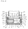
- cylindrical body 1 and brush 2 form a rotary brush. Bristles are transplanted in a V-shape on the outer surface of cylindrical body 1 to form brush 2. In place of the brush, an agitator, a thin plate scraper, or the like, may be used depending on objectives or applications.
- Numeral 3 denotes a reduction gear bracket which is a part of speed reduction mechanism, and a motor bracket 4 holds a motor housed in cylindrical body 1.
- First opening 6, a ventilation hole, is provided on an edge portion of the outer wall of cylindrical body 1.
- Numeral 32 denotes a ventilation hole provided in motor bracket 4.
- the bristle arrangement of brush 2, or agitator is not limited to the V-shape, but may be of a helical shaped or another patterns for an improved capacity of dust agitation/collection.
- numeral 7 denotes a rotor of the motor
- stator 8 of the motor is mounted inside of motor bracket 4, and is disposed in an annular space between rotor 7 and bracket 4.
- Rotor shaft 9 rotates together with the rotor 7.
- Commutator 10 is disposed on an edge portion of rotor 7 and carbon brush 5 slidably contacts the circumference of commutator 10.
- Rotor 7 is powered through carbon brush 5 and commutator 10.
- a first bearing 11 receives the outer wall of motor bracket 4 press-fitted in its inner wall, while an outer ring of bearing 11 is press fitted into an inner wall of cylindrical body 1 at its left edge so that cylindrical body 1 is journaled at the motor end.
- Carbon brush 5 is mounted to part of motor bracket 4 which outwardly protrudes from cylindrical body 1 at the motor side, i.e. the motor bracket is provided outside of first bearing 11. Carbon brush 5 is mounted outside of rotational cylindrical body 1 so that wiring for power is easily provided to carbon brush 5, and so that a worn-out carbon brush could be easily replaced.
- Numeral 12 denotes a third opening provided in the motor bracket 4 at the right end for taking the outside air into the motor for cooling.
- Numeral 13 denotes a second bearing which is press fitted to reduction gear bracket 3 and supports the right end (opposite end to the motor) of the rotor shaft with the inner ring.
- Numeral 14 denotes a third bearing the outer ring of which is press fitted to a portion of cylindrical body 1 (a recess on the wall opposite to motor of cylindrical body 1), while rotor shaft 9 is press fitted to the inner ring of the bearing.
- First gear 15 is fixed to the rotor shaft 9, and is held by and between the second bearing 13 and the third bearing 14.
- Second gear 16 is supported by pin 17 provided in reduction gear bracket 3, for transmitting the rotation of first gear 15 to third gear 18 formed around the inner edge of cylindrical body 1; thus cylindrical body 1 is driven at a reduced speed.
- Motor bearings 19 are provided at both ends of the rotor 7, the bearings 19 are held by motor bracket 4.
- cylindrical body 11 allows cylindrical body 11 to rotate in an accurate and smooth manner with less noise and to be journaled by first bearing 11 and third bearing 14.
- efficiency of the motor is further promoted. Since heavy items, such as the motor, the reduction gear and its bracket, are placed on both ends of cylindrical body 11 in well balanced manner, cylindrical body 11 rotates with little wobble thanks to the well-balanced weight. Further, heavy items are placed at both ends, i.e. near to the bearings, so that few chances of rotational wobble are available.
- Detector 20 detects abnormal pressure in a sucking passage, temperature or electric current and breaks electric supply to the motor; thus the detector is expected to function as a safety device for protecting the motor or preventing unusual heat generation.
- the detector detects these abnormal states so that the motor is protected and overheating is avoided. Sucked in air is utilized to cool down the motor (detailed later). However, when sucking power is lowered because a filter provided in a dust chamber (48 in Fig. 10) is clogged or the like, the detector detects a lowered pressure in the sucking passage. Since the lowered pressure causes insufficient cooling of the motor, the detector can shut the current-supply to the motor to avoid overheat.
- Outside-air taking room 21 introduces outside-air to first opening 6 provided on cylindrical body 1.
- Floor nozzle 22 incorporates the rotary brush therein.
- a first end of hose 23 is coupled to sucking mouth 38 provided at rear portion of floor nozzle 22.
- a second end of hose 23 leads to dust chamber 48 and electric blower 43, both are situated in the cleaner body that is disposed behind the floor nozzle (Ref. Fig. 10).
- Partition 27 is protrusively provided in floor nozzle 22 so that partition 27 surrounds both ends of cylindrical body 1.
- Partition 27 separates sucking chamber 28, outside-air taking room 28 where first opening 6 is situated and a second opening 32 provided on the motor bracket. Chamber 28 is operated by the sucking power of the electric blower.
- Partition 27 has communication hole 27a on second opening 32 side, and the sucking operation is obtained through hole 27a, which aims to cool the motor by sucking outside-air through outside-air taking room 21, first opening 6, cylindrical body 1, motor bracket 4 and second opening 32.
- the accompanying drawing in accordance with this exemplary embodiment shows two pieces of hose 23.
- communication hole 27a can communicate sucking chamber 28 so that sucking power directly works through second opening 32. Therefore, the motor can be cooled down more efficiently.
- sucking mouth 38 is placed closely to communication hole 27a so that mouth 38 can get strong sucking power.
- air sucked through second opening 32 and communication hole "27a” efficiently transfers the dust collected by brush 2 and moved in sucking chamber 28 laterally into hose 23.
- hose 23 opposite to communication hole “27a” arranges sucking mouth 38 and first opening 6 on the same side of floor nozzle 22 with regard to lateral direction.
- the rotary brush is placed in sucking chamber 28, and opening 45 is provided on the bottom of nozzle 22 corresponding to the lower portion of the rotary brush so that the rotary brush faces the floor side.
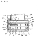
- Fig. 3 illustrates a more compact structure where carbon brush 5 is integrated into cylindrical body 1. This structure allows floor nozzle 22 to utilize its width more effectively, or to be smaller in size.
- Fig. 3 also illustrates that fin 24 is provided on rotor shaft 9, fin 25 is provided on the inner wall of cylindrical body 11, and fin 26 is protruded on a side wall of cylindrical body 1. These arrangements eliminates the speed reduction mechanism and realizes direct driving as well as blows air inside the motor in the cylindrical body 1 as wind creating means to cool the motor.
- Each fin can be independently used or combined with each other depending on the cooling effect.
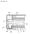
- Fig. 4 illustrates that manual reset type thermo-protector 29 functions as a detector. It has heat-sensitive section 30 and manual reset button 31. In an operation, once a temperature rises abnormally, the apparatus stops working, and this manual reset button 31 prevents the apparatus from automatically starting again when the temperature lowers naturally. The apparatus can be started again by operating the manual reset button after identifying the abnormality.
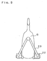
- Fig.5 illustrates a rotary brush device incorporating an outer rotor motor.
- the major point of difference as compared to Fig.3 includes; rotor 33 comprising a magnet is fitted to inner wall of cylindrical body 1, stator 34 is fixed to motor shaft 35 of which both ends are held and fixed by floor nozzle 22, cylindrical body 1 at the left end is journaled by the outer ring of first bearing 11 which is press fitted in the inner ring with outer wall of stator bracket 36, while at the right end of cylindrical body 1 is journaled with its side wall by bearing 37.
- Sucking intake 38 for hose 23 to suck the air from sucking chamber 28 of floor nozzle 22.
- hose 23 has been provided for two. However, there may be one hose 23 only, in which case only one sucking intake may be provided at one end.
- outside-air intake 39 is provided on the top portion of floor nozzle 22.
- the portion where outside-air intake 39 is placed corresponds to space F (ref. Fig. 2) of outside-air taking room 21 separated by partition 27 from sucking chamber 28.
- second opening 32 faces space “E” separated from sucking chamber 28 which is placed opposite to outside-air intake 39.
- partition 27 with regard to space “E” has communication hole “27a” leading to sucking chamber 28. Therefore, when electric blower 43 exerts its sucking power to sucking chamber 28, sucking power is effected to communication hole "27a", second opening 32, inside of cylindrical body 1, first opening 21 and space "F” sequentially, thereby taking outside-air from outside-air intake 39.
- vacuum cleaner body "G” incorporates dust chamber 48 and blower 43, and the lower part of the body is mounted to the rear portion of floor nozzle 22 so that body "G" can be arbitrarily slanted.
- numeral 43 denotes an electric blower for sucking the air
- dust bag 44 is provided within dust chamber 48
- sucking mouth 45 is provided on the bottom of nozzle 22
- rotary brush 46 is provided within nozzle 22.
- the floor nozzle and the rotary brush shown in Fig. 1 though Fig. 7 are employed.
- rotary brush "46a" has bristles transplanted in a V-shape. Brushes 47 are fixedly mounted at both ends of the sucking mouth 45, and brushes 47 have bristles planted with a certain orientation for picking up lint and the like.
- the rotary brush is used for only one. It is of course possible to form a rotary brush device employing a plurality of rotary brushes.
- Fig.12(a) includes rotary brush 46 discussed above, and an electric apparatus 49 having a pair of floor rollers 54 in the front and the rear sections respectively incorporating an invented rotary brush device.
- Floor contact roller 50 is provided at the bottom end of actuator 52 that is urged down by a spring 51.
- floor contact roller 50 is lifted up to turn switch 53, situated in the OFF position, to the ON position which activates a motor built in a rotary brush device.
- Fig.12(b) illustrates a state where carpet 55 placed on floor 42 is detected and the switch 53 is turned ON.
- Fig.12(c) is an electrical circuit including power source 57, detection switch 53, motor 56 built in the rotary brush device, and variable resistor 58 for controlling the rotation of the motor which is to be discussed later.
- An electric vacuum cleaner for floor carpet having the construction discussed above starts operation when floor contact roller 50 is pushed up by carpet 55.
- handle 59 is tiltably attached to floor nozzle 22; when it is stood upright, switch 60 is turned OFF to break electric supply to the rotary brush device.
- Controller 61 is provided on the handle 59, and controls a rotation speed of rotary brush 46 through the above described variable resistor 58.
- Filter 62 is provided in dust chamber 48 for capturing the dusts stirred by rotary brush 46.
- Dust detector 63 comprises light-emitting element and light-sensing element, etc. and detects quantity of dusts being sucked into dust chamber 48. The dust detector senses the shift of output from the light-sensing element.
- the rotation speed of rotary brush 46 is varied in accordance with the dust quantity.
- Fig.13(b) illustrates the electrical circuit of detector 63; where, phase controller 64 controls the rotation speed of the motor in accordance with result of the above described dust sensing.
- controller 61 selects a rotational speed depending on the dust sensing
- phase controller 64 follows the control process discussed above. In addition to this, high, mid, and low speeds are prepared so that users can arbitrarily select the rotational speed among them. This structure allows the vacuum cleaner to be handled with ease and work efficiently in terms of power consumption.
Landscapes
- Engineering & Computer Science (AREA)
- Mechanical Engineering (AREA)
- Nozzles For Electric Vacuum Cleaners (AREA)
- Motor Or Generator Cooling System (AREA)
- Electric Vacuum Cleaner (AREA)
- Connection Of Motors, Electrical Generators, Mechanical Devices, And The Like (AREA)
- Electric Suction Cleaners (AREA)
Claims (28)
- Rotationsbürstenanordnung mit einem zylindrischen Körper (1) mit einem Einbaumotor, der in dem zylindrischen Körper untergebracht ist, dessen Außenwand mit einer Bürste (2), einem Dünnblech-Rührwerk oder einem Dünnblech-Abstreifer versehen ist, wobei der zylindrische Körper (1) in der Nähe des einen Endes mit einer ersten Öffnung (6), die mit der Außenluft verbunden ist, und einer zweiten Öffnung (32) an dem anderen Ende versehen ist, wobei die erste Öffnung (6) und die zweite Öffnung (32) über das Innere des Motors miteinander verbunden sind.
- Rotationsbürstenanordnung nach Anspruch 1, dadurch gekennzeichnet, dass der Motor einen Läufer (7) und einen um eine Außenwand des Läufers vorgesehenen Ständer (8) aufweist und eine Welle (9) des Läufers durch Direktverbindung oder über ein Reduktionsgetriebe (3) mit dem zylindrischen Körper verbunden ist.
- Rotationsbürstenanordnung nach Anspruch 1, dadurch gekennzeichnet, dass der Motor einen Ständer und einen Läufer, der um eine Außenwand des Ständers beliebig drehbar ist, aufweist und der Läufer über ein Reduktionsgetriebe mit dem zylindrischen Körper in Eingriff ist.
- Rotationsbürstenanordnung nach Anspruch 1, dadurch gekennzeichnet, dass eine Motorhalterung (4) mit einer dritten Öffnung (12) versehen ist, die mit der ersten Öffnung und der zweiten Öffnung verbunden ist.
- Rotationsbürstenanordnung nach Anspruch 1, dadurch gekennzeichnet, dass Wind-Erzeugungsmittel (24) in dem zylindrischen Körper vorgesehen sind.
- Rotationsbürstenanordnung nach Anspruch 5, dadurch gekennzeichnet, dass die Wind-Erzeugungsmittel von einer Rippe gebildet werden, die mindestens entweder an einer Läuferwelle (24), einer Innenwandfläche (25) des zylindrischen Körpers oder einer Seitenwandfläche (26) des zylindrischen Körpers vorgesehen ist.
- Rotationsbürstenanordnung nach Anspruch 1, dadurch gekennzeichnet, dass die erste Öffnung auf einer Seite vorgesehen ist, die dem Motor des zylindrischen Körpers gegenüber liegt, während die zweite Öffnung auf der Motorseite des zylindrischen Körpers vorgesehen ist.
- Rotationsbürstenanordnung nach Anspruch 7, dadurch gekennzeichnet, dass die zweite Öffnung in einer Richtung vorgesehen ist, die senkrecht zur Achse einer Rotationsbürste ist.
- Rotationsbürstenanordnung nach Anspruch 1, dadurch gekennzeichnet, dass ein Messfühler (29) zum Messen eines Drucks oder einer Temperatur an einer Stelle vorgesehen ist, die mit dem Inneren des Motors verbunden ist, und eine Stromversorgung für den Motor entsprechend einem Ergebnis der von dem Messfühler durchgeführten Messung gesteuert wird.
- Rotationsbürstenanordnung nach Anspruch 1, dadurch gekennzeichnet, dass ein Messfühler zum Messen des in dem Motor fließenden elektrischen Stroms vorgesehen ist und eine Stromversorgung für den Motor entsprechend einem Ergebnis der von dem Messfühler durchgeführten Messung gesteuert wird.
- Rotationsbürstenanordnung nach Anspruch 1, dadurch gekennzeichnet, dass das Rührwerk oder der Abstreifer an der Außenwand des zylindrischen Körpers in einer Spiral- oder V-Form vorgesehen ist.
- Elektrische Vorrichtung mit mindestens einer Rotationsbürstenanordnung nach Anspruch 1.
- Elektrische Vorrichtung mit der Rotationsbürstenanordnung nach Anspruch 9, dadurch gekennzeichnet, dass ein Handrückstell-Wärmeschutz (29) als Messfühler zum Messen einer Temperatur vorgesehen ist und ein Temperaturmessfühlteil des Messfühlers auf der Motorseite angeordnet ist, während ein Rückstellknopf (31) auf einer Außenfläche der Vorrichtung angeordnet ist.
- Elektrische Vorrichtung mit einer Bodendüse (22), die eine Saugkammer (28) hat, die mit einem elektrischen Gebläse zum Saugen verbunden ist und mit einer nach unten gerichteten Öffnung (38) versehen ist, dadurch gekennzeichnet, dass die Saugkammer mit der Rotationsbürstenanordnung nach Anspruch 1 versehen ist.
- Elektrische Vorrichtung mit:einem elektrischen Gebläse zum Saugen undeiner Bodendüse mit einer Saugkammer, die mit einem elektrischen Gebläse zum Saugen verbunden ist und mit einer nach unten gerichteten Öffnung versehen ist,dadurch gekennzeichnet, dass die Saugkammer mit der Rotationsbürstenanordnung nach Anspruch 1 versehen ist, eine erste und eine zweite Öffnung von der Saugkammer getrennt sind und ein Außenluft-Einlass auf einer mit der ersten Öffnung verbundenen Außenfläche der Vorrichtung vorgesehen ist.
- Elektrische Vorrichtung nach Anspruch 15, dadurch gekennzeichnet, dass die zweite Öffnung mit dem elektrischen Gebläse verbunden ist.
- Elektrische Vorrichtung nach Anspruch 14 oder 15, dadurch gekennzeichnet, dass der Außenluft-Einlass (39) auf einer Oberseite der Bodendüse vorgesehen ist.
- Elektrische Vorrichtung nach Anspruch 15 oder 16, dadurch gekennzeichnet, dass das elektrische Gebläse und die Saugkammer mit mindestens einem Schlauch (23) verbunden sind.
- Elektrische Vorrichtung nach Anspruch 15, dadurch gekennzeichnet, dass die zweite Öffnung auf der Seite eines Saugmunds angeordnet ist, der das elektrische Gebläse mit der Saugkammer verbindet.
- Elektrische Vorrichtung nach Anspruch 15, dadurch gekennzeichnet, dass die zweite Öffnung auf einer Seite angeordnet ist, die dem Saugmund gegenüberliegt, der das elektrische Gebläse mit der Saugkammer verbindet, und Motor-Kühlluft, die aus der zweiten Öffnung strömt, eine Rotationsbürste umströmt.
- Elektrische Vorrichtung nach Anspruch 15, dadurch gekennzeichnet, dass die Bodendüse auf ihrer Unterseite eine Öffnung hat, die so mit der zweiten Öffnung verbunden ist, dass die Öffnung mit der Saugkammer verbunden ist.
- Elektrische Vorrichtung nach Anspruch 14 oder 15, dadurch gekennzeichnet, dass ein Messfühler (20) zum Messen eines Drucks vorgesehen ist und eine Stromversorgung für den Motor entsprechend einem Ergebnis der von dem Messfühler durchgeführten Messung gesteuert wird.
- Elektrische Vorrichtung nach Anspruch 14, dadurch gekennzeichnet, dass eine Bürste (47) auf einer Unterseite der Bodendüse an einer Stelle zwischen einer Rotationsbürste (46) und entsprechenden Seitenenden der Bodendüse vorgesehen ist.
- Elektrische Vorrichtung mit:einem elektrischen Gebläse zum Saugen;einer Staubkammer (48) zum Aufnehmen von Staub;einer Bodendüse, die mit einer Saugkammer versehen ist, die eine nach unten gerichtete Öffnung hat;einem Saugmund, der an einer der Wände der Saugkammer vorgesehen ist und mit dem elektrischen Gebläse verbunden ist; undder Rotationsbürstenanordnung nach Anspruch 1, die in die Saugkammer eingebaut ist, dadurch gekennzeichnet, dass die Bodendüse an einem oberen Teil mit einem mit der ersten Öffnung verbundenen Außenluft-Einlass versehen ist und der Saugmund in Bezug auf die Breite der Bodendüse auf der gleichen Seite wie die erste Öffnung angeordnet ist.
- Elektrische Vorrichtung mit:einem Paar Laufrollen (50), die jeweils vorn und hinten vorgesehen sind;einem Bodensensor zum Ermitteln einer Bodenart;einem Schalter (53), der in Verbindung mit dem Bodensensor arbeitet; undder Rotationsbürstenanordnung nach Anspruch 1,dadurch gekennzeichnet, dass der zylindrische Körper entsprechend der Bodenart in Drehung versetzt wird.
- Elektrische Vorrichtung mit:einer Bodendüse, die die Rotationsbürstenanordnung nach Anspruch 1 enthält und eine Saugkammer mit einer nach unten gerichteten Öffnung hat;einem elektrischen Gebläse zum Saugen;einer Staubkammer zum Aufnehmen von Staub undeiner Griffstange (59), die kippbar an der Bodendüse angebracht ist,dadurch gekennzeichnet, dass die Drehung des zylindrischen Körpers der Rotationsbürstenanordnung unterbrochen wird, wenn die Griffstange im Wesentlichen senkrecht gestellt wird.
- Elektrische Vorrichtung nach Anspruch 26, dadurch gekennzeichnet, dass ein Steuergerät zum Steuern der Drehung des zylindrischen Körpers der Rotationsbürstenanordnung an einem Teil der Griffstange vorgesehen ist.
- Elektrische Vorrichtung mit
einer Bodendüse, die die Rotationsbürstenanordnung nach Anspruch 1 enthält und eine Saugkammer mit einer nach unten gerichteten Öffnung hat;
einem elektrischen Gebläse zum Saugen;
einer Staubkammer zum Aufnehmen von Staub und
einem Staubdetektor (63), der an einem Teil der Saugstrecke, die die Saugkammer mit dem elektrischen Gebläse verbindet, vorgesehen ist,
dadurch gekennzeichnet, dass die Drehung des zylindrischen Körpers der Rotationsbürstenanordnung entsprechend einem Ausgangssignal des Staubdetektors gesteuert wird.
Applications Claiming Priority (3)
| Application Number | Priority Date | Filing Date | Title |
|---|---|---|---|
| US5502098A | 1998-04-03 | 1998-04-03 | |
| US55020 | 1998-04-03 | ||
| EP99106662A EP0947155B1 (de) | 1998-04-03 | 1999-04-01 | Rotationsbürstenanordnung und damit ausgerüsteter Staubsauger |
Related Parent Applications (1)
| Application Number | Title | Priority Date | Filing Date |
|---|---|---|---|
| EP99106662A Division EP0947155B1 (de) | 1998-04-03 | 1999-04-01 | Rotationsbürstenanordnung und damit ausgerüsteter Staubsauger |
Publications (2)
| Publication Number | Publication Date |
|---|---|
| EP1297773A1 EP1297773A1 (de) | 2003-04-02 |
| EP1297773B1 true EP1297773B1 (de) | 2006-06-14 |
Family
ID=21995046
Family Applications (3)
| Application Number | Title | Priority Date | Filing Date |
|---|---|---|---|
| EP99106662A Expired - Lifetime EP0947155B1 (de) | 1998-04-03 | 1999-04-01 | Rotationsbürstenanordnung und damit ausgerüsteter Staubsauger |
| EP02025302A Expired - Lifetime EP1297773B1 (de) | 1998-04-03 | 1999-04-01 | Rotationsbürstenanordnung und damit ausgerüsteter Staubsauger |
| EP02025303A Expired - Lifetime EP1293158B1 (de) | 1998-04-03 | 1999-04-01 | Rotationsbürstenanordnung und damit ausgerüsteter Staubsauger |
Family Applications Before (1)
| Application Number | Title | Priority Date | Filing Date |
|---|---|---|---|
| EP99106662A Expired - Lifetime EP0947155B1 (de) | 1998-04-03 | 1999-04-01 | Rotationsbürstenanordnung und damit ausgerüsteter Staubsauger |
Family Applications After (1)
| Application Number | Title | Priority Date | Filing Date |
|---|---|---|---|
| EP02025303A Expired - Lifetime EP1293158B1 (de) | 1998-04-03 | 1999-04-01 | Rotationsbürstenanordnung und damit ausgerüsteter Staubsauger |
Country Status (9)
| Country | Link |
|---|---|
| US (3) | US6400048B1 (de) |
| EP (3) | EP0947155B1 (de) |
| JP (1) | JPH11313786A (de) |
| KR (1) | KR100384980B1 (de) |
| CN (2) | CN1322833C (de) |
| AU (1) | AU754001B2 (de) |
| CA (2) | CA2653510C (de) |
| DE (3) | DE69931971T2 (de) |
| ES (3) | ES2265471T3 (de) |
Cited By (1)
| Publication number | Priority date | Publication date | Assignee | Title |
|---|---|---|---|---|
| WO2008128751A1 (de) * | 2007-04-24 | 2008-10-30 | Miele & Cie. Kg | Verfahren zur betreiben einer rotationsbürstenanordnung und rotationsbürstenanordnung zur durchführung eines solchen verfahrens |
Families Citing this family (173)
| Publication number | Priority date | Publication date | Assignee | Title |
|---|---|---|---|---|
| KR100384980B1 (ko) * | 1998-04-03 | 2003-06-02 | 마츠시타 덴끼 산교 가부시키가이샤 | 회전 브러시 장치 및 이를 이용한 전기 기구 |
| US6260232B1 (en) * | 1998-09-22 | 2001-07-17 | Marc O. Nelson | Surface cleaning apparatus |
| US6277164B1 (en) | 1999-04-06 | 2001-08-21 | Oreck Holdings, Llc | Balanced flow vacuum cleaner bag interface |
| US6148473A (en) | 1999-04-06 | 2000-11-21 | Oreck Holdings, Llc | Balanced flow vacuum cleaner |
| JP4078756B2 (ja) * | 1999-06-17 | 2008-04-23 | 松下電器産業株式会社 | 電動装置 |
| US8788092B2 (en) | 2000-01-24 | 2014-07-22 | Irobot Corporation | Obstacle following sensor scheme for a mobile robot |
| US7155308B2 (en) | 2000-01-24 | 2006-12-26 | Irobot Corporation | Robot obstacle detection system |
| US8412377B2 (en) | 2000-01-24 | 2013-04-02 | Irobot Corporation | Obstacle following sensor scheme for a mobile robot |
| US6956348B2 (en) | 2004-01-28 | 2005-10-18 | Irobot Corporation | Debris sensor for cleaning apparatus |
| GB2398232B (en) * | 2000-10-03 | 2005-03-23 | Matsushita Electric Corp | Agitator drive motor and fan motor arrangements in vacuum cleaners |
| GB2406044C (en) * | 2000-10-03 | 2011-10-26 | Matsushita Electric Corp | Bagless vacuum cleaner having agitator with integral motor |
| US7571511B2 (en) | 2002-01-03 | 2009-08-11 | Irobot Corporation | Autonomous floor-cleaning robot |
| US6690134B1 (en) | 2001-01-24 | 2004-02-10 | Irobot Corporation | Method and system for robot localization and confinement |
| US6655650B2 (en) * | 2001-04-12 | 2003-12-02 | Western Forms, Inc. | Concrete forming panel with flexible barrier |
| KR100414086B1 (ko) | 2001-06-09 | 2004-01-07 | 엘지전자 주식회사 | 파워브러쉬를 구비한 진공청소기의 흡입헤드 |
| US8396592B2 (en) | 2001-06-12 | 2013-03-12 | Irobot Corporation | Method and system for multi-mode coverage for an autonomous robot |
| US7429843B2 (en) | 2001-06-12 | 2008-09-30 | Irobot Corporation | Method and system for multi-mode coverage for an autonomous robot |
| KR20020096112A (ko) * | 2001-06-16 | 2002-12-31 | 엘지전자 주식회사 | 진공 청소기의 흡입헤드 |
| KR100429991B1 (ko) * | 2001-06-26 | 2004-05-04 | 엘지전자 주식회사 | 파워브러쉬를 구비한 진공청소기의 흡입헤드 |
| USD483534S1 (en) | 2001-07-16 | 2003-12-09 | Marc O. Nelson | Scrubber |
| KR100438606B1 (ko) * | 2001-08-22 | 2004-07-02 | 엘지전자 주식회사 | 파워브러쉬를 구비한 진공청소기의 흡입헤드 |
| KR100438607B1 (ko) * | 2001-08-27 | 2004-07-02 | 엘지전자 주식회사 | 파워브러쉬를 구비한 진공청소기의 흡입헤드 |
| JP2003204904A (ja) * | 2001-11-09 | 2003-07-22 | Sharp Corp | 電気掃除機 |
| JP2003144359A (ja) * | 2001-11-12 | 2003-05-20 | Sharp Corp | 電気掃除機 |
| US9128486B2 (en) | 2002-01-24 | 2015-09-08 | Irobot Corporation | Navigational control system for a robotic device |
| CA2421314A1 (en) * | 2002-03-08 | 2003-09-08 | Erik J. Hitzelberger | Self-propelled vacuum cleaner with reversible rotary agitator |
| AU2003215456A1 (en) * | 2002-03-12 | 2003-09-22 | Cube Investments Limited | Suction motor for vacuum cleaner |
| USD478698S1 (en) | 2002-04-05 | 2003-08-19 | Superior Brush Company | Agitator for a vacuum cleaner |
| US6848147B2 (en) | 2002-04-08 | 2005-02-01 | Royal Appliance Mfg. Co. | Internally driven agitator |
| US20040010884A1 (en) * | 2002-07-22 | 2004-01-22 | Hitzelberger J. Erik | Floor care apparatus with deep cleaning action |
| GB2391459A (en) * | 2002-08-09 | 2004-02-11 | Dyson Ltd | A surface treating appliance with increased manoeuverability |
| US8428778B2 (en) | 2002-09-13 | 2013-04-23 | Irobot Corporation | Navigational control system for a robotic device |
| US8386081B2 (en) | 2002-09-13 | 2013-02-26 | Irobot Corporation | Navigational control system for a robotic device |
| US20040134014A1 (en) * | 2003-01-10 | 2004-07-15 | Hawkins Thomas W. | Vacuum cleaner having a variable speed brushroll |
| US7208892B2 (en) * | 2003-05-23 | 2007-04-24 | The Hoover Company | Power management system for a floor care appliance |
| US20050015918A1 (en) * | 2003-07-22 | 2005-01-27 | Royal Appliance Mfg. Co. | Brushless dc drive mechanism for seld propelled aplicance |
| DE10336827A1 (de) * | 2003-08-11 | 2005-03-10 | Bsh Bosch Siemens Hausgeraete | Staubsauger mit einer Gebläsekapsel |
| US7332890B2 (en) | 2004-01-21 | 2008-02-19 | Irobot Corporation | Autonomous robot auto-docking and energy management systems and methods |
| US7251858B2 (en) * | 2004-01-23 | 2007-08-07 | Panasonic Corporation Of North America | Floor care apparatus with multiple agitator speeds and constant suction power |
| US20050160555A1 (en) * | 2004-01-27 | 2005-07-28 | Panasonic Corporation Of North America | Vacuum cleaner with twin independently driven agitators |
| US20050172447A1 (en) * | 2004-02-05 | 2005-08-11 | Panasonic Corporation Of North America | Floor cleaning apparatus with twin agitators having different diameters |
| DE112005000738T5 (de) | 2004-03-29 | 2007-04-26 | Evolution Robotics, Inc., Pasadena | Verfahren und Vorrichtung zur Positionsbestimmung unter Verwendung von reflektierten Lichtquellen |
| GB2414283A (en) * | 2004-05-06 | 2005-11-23 | Dyson Ltd | A slip responsive clutch in a vacuum cleaner |
| US6856113B1 (en) | 2004-05-12 | 2005-02-15 | Cube Investments Limited | Central vacuum cleaning system motor control circuit mounting post, mounting configuration, and mounting methods |
| WO2006002385A1 (en) | 2004-06-24 | 2006-01-05 | Irobot Corporation | Programming and diagnostic tool for a mobile robot |
| US8972052B2 (en) | 2004-07-07 | 2015-03-03 | Irobot Corporation | Celestial navigation system for an autonomous vehicle |
| US7706917B1 (en) | 2004-07-07 | 2010-04-27 | Irobot Corporation | Celestial navigation system for an autonomous robot |
| EP1799087A4 (de) | 2004-09-17 | 2009-08-12 | Cube Invest Ltd | Reinigungsvorrichtungsgriff und gehäuseabschnitte für einen reinigungsvorrichtungsgriff |
| JP2006136512A (ja) * | 2004-11-12 | 2006-06-01 | Matsushita Electric Ind Co Ltd | 電気掃除機 |
| US8392021B2 (en) | 2005-02-18 | 2013-03-05 | Irobot Corporation | Autonomous surface cleaning robot for wet cleaning |
| US7389156B2 (en) | 2005-02-18 | 2008-06-17 | Irobot Corporation | Autonomous surface cleaning robot for wet and dry cleaning |
| KR101247933B1 (ko) | 2005-02-18 | 2013-03-26 | 아이로보트 코퍼레이션 | 습식 및 건식 청소를 위한 자동 표면 청소 로봇 |
| US7620476B2 (en) | 2005-02-18 | 2009-11-17 | Irobot Corporation | Autonomous surface cleaning robot for dry cleaning |
| US8930023B2 (en) | 2009-11-06 | 2015-01-06 | Irobot Corporation | Localization by learning of wave-signal distributions |
| US7900315B2 (en) | 2005-10-07 | 2011-03-08 | Cube Investments Limited | Integrated central vacuum cleaner suction device and control |
| US7690075B2 (en) | 2005-10-07 | 2010-04-06 | Cube Investments Limited | Central vacuum cleaner control, unit and system with contaminant sensor |
| CA2562804C (en) | 2005-10-07 | 2014-12-09 | Cube Investments Limited | Vacuum cleaner cross-control |
| CA2562810C (en) | 2005-10-07 | 2015-12-08 | Cube Investments Limited | Central vacuum cleaner multiple vacuum source control |
| EP2816434A3 (de) | 2005-12-02 | 2015-01-28 | iRobot Corporation | Roboter mit autonomem Wirkungsbereich |
| KR101099808B1 (ko) | 2005-12-02 | 2011-12-27 | 아이로보트 코퍼레이션 | 로봇 시스템 |
| EP2251757B1 (de) * | 2005-12-02 | 2011-11-23 | iRobot Corporation | Abdeckungsrobotermobilität |
| ES2706729T3 (es) | 2005-12-02 | 2019-04-01 | Irobot Corp | Sistema de robot |
| WO2007065034A1 (en) | 2005-12-02 | 2007-06-07 | Irobot Corporation | Modular robot |
| US7509707B2 (en) * | 2006-02-06 | 2009-03-31 | Panasonic Corporation Of North America | Floor cleaning apparatus with dirt detection sensor |
| EP1836941B1 (de) * | 2006-03-14 | 2014-02-12 | Toshiba TEC Kabushiki Kaisha | Elektrischer Staubsauger |
| ES2583374T3 (es) | 2006-05-19 | 2016-09-20 | Irobot Corporation | Eliminación de residuos de robots de limpieza |
| US8417383B2 (en) | 2006-05-31 | 2013-04-09 | Irobot Corporation | Detecting robot stasis |
| GB2440717A (en) * | 2006-08-08 | 2008-02-13 | Dyson Technology Ltd | Circuit breaker system for a vacuum cleaner |
| US20080172825A1 (en) * | 2007-01-23 | 2008-07-24 | Weiss Scot H | Device and a system for using a rotary brush to clean a surface |
| US20080229885A1 (en) * | 2007-03-22 | 2008-09-25 | Mah Pat Y | Jar opener |
| EP2574265B1 (de) | 2007-05-09 | 2015-10-14 | iRobot Corporation | Kompakter Roboter mit autonomer Reichweite |
| US8256059B2 (en) * | 2008-02-19 | 2012-09-04 | Electrolux Home Care Products, Inc. | Brushroll with sound reducing features |
| US10117553B2 (en) | 2008-03-17 | 2018-11-06 | Aktiebolaget Electrolux | Cleaning nozzle for a vacuum cleaner |
| CA2749287C (en) * | 2009-01-09 | 2015-06-02 | Dematic Corp. | Dual power motorized roller |
| IT1399016B1 (it) * | 2009-03-03 | 2013-04-05 | Salvador | Sistema aspirante per macchine spazzolatrici/pulitrici. |
| US9591953B2 (en) | 2009-03-13 | 2017-03-14 | Omachron Intellectual Property Inc. | Surface cleaning apparatus |
| US9226633B2 (en) | 2009-03-13 | 2016-01-05 | Omachron Intellectual Property Inc. | Surface cleaning apparatus |
| US20100236013A1 (en) * | 2009-03-17 | 2010-09-23 | Electrolux Home Care Products, Inc. | Vacuum Cleaner Sensor |
| JP2011056096A (ja) * | 2009-09-11 | 2011-03-24 | Mitsubishi Electric Corp | 電気掃除機用吸込具及び電気掃除機 |
| JP2011075170A (ja) * | 2009-09-30 | 2011-04-14 | Sanyo Electric Co Ltd | 空気調和機 |
| GB2474472B (en) | 2009-10-15 | 2013-10-23 | Dyson Technology Ltd | A surface treating appliance |
| GB2474464B (en) | 2009-10-15 | 2013-11-20 | Dyson Technology Ltd | A surface treating appliance |
| GB2474465B (en) | 2009-10-15 | 2013-10-23 | Dyson Technology Ltd | A surface treating appliance |
| GB2474470B (en) | 2009-10-15 | 2013-10-23 | Dyson Technology Ltd | A surface treating appliance |
| GB2474469B (en) | 2009-10-15 | 2013-11-13 | Dyson Technology Ltd | A surface treating appliance |
| GB0918027D0 (en) | 2009-10-15 | 2009-12-02 | Dyson Technology Ltd | A surface trating appliance |
| GB2474462B (en) | 2009-10-15 | 2013-12-11 | Dyson Technology Ltd | A surface treating appliance with domed-shaped wheels |
| GB2474473B (en) | 2009-10-15 | 2013-10-23 | Dyson Technology Ltd | A surface treating appliance |
| GB2474463B (en) | 2009-10-15 | 2013-11-13 | Dyson Technology Ltd | A surface treating appliance |
| GB2474475B (en) | 2009-10-15 | 2013-10-23 | Dyson Technology Ltd | A surface treating appliance |
| MX381992B (es) | 2010-02-15 | 2025-03-04 | Bissell Homecare Inc | Aspiradora de alfombra. |
| US8800107B2 (en) | 2010-02-16 | 2014-08-12 | Irobot Corporation | Vacuum brush |
| JP4985804B2 (ja) * | 2010-03-17 | 2012-07-25 | パナソニック株式会社 | 電気掃除機用吸込具及びそれを用いた電気掃除機 |
| IT1399635B1 (it) * | 2010-04-26 | 2013-04-26 | Valentini | Apparato di comunicazione wireless per aspirapolvere industriale. |
| SE534963C2 (sv) | 2010-06-29 | 2012-02-28 | Electrolux Ab | Dammindikator för en dammsugare |
| SE534962C2 (sv) | 2010-06-29 | 2012-02-28 | Electrolux Ab | Dammdetekteringssystem för en dammsugare |
| WO2012077227A1 (ja) * | 2010-12-10 | 2012-06-14 | 三菱電機株式会社 | 回転電機 |
| EP2659260B1 (de) | 2010-12-30 | 2019-11-20 | iRobot Corporation | Überwachung von debris |
| JP5826607B2 (ja) * | 2011-01-31 | 2015-12-02 | アスモ株式会社 | モータ |
| CN111281266B (zh) | 2011-04-29 | 2021-12-10 | 艾罗伯特公司 | 移动清洁机器人和自主覆盖机器人 |
| US11471020B2 (en) | 2011-04-29 | 2022-10-18 | Irobot Corporation | Robotic vacuum cleaning system |
| EP2770892B1 (de) | 2011-10-26 | 2015-09-23 | Aktiebolaget Electrolux | Reinigungsdüse für einen staubsauger |
| US8914940B2 (en) * | 2011-11-03 | 2014-12-23 | Techtronic Floor Care Technology Limited | Vacuum axle with a motor embedded therein and wheels |
| GB2498351B (en) * | 2012-01-10 | 2014-06-18 | Dyson Technology Ltd | A cleaner head for a vacuum cleaner |
| CN104080384B (zh) | 2012-02-02 | 2016-10-12 | 伊莱克斯公司 | 用于真空吸尘器吸嘴的清洁装置 |
| GB2499214B (en) | 2012-02-08 | 2014-03-26 | Dyson Technology Ltd | A cleaner-head for a vacuum cleaner |
| GB2499213B (en) * | 2012-02-08 | 2016-10-19 | Dyson Technology Ltd | A cleaner-head for a vacuum cleaner |
| CA2868616C (en) | 2012-03-27 | 2020-03-31 | Tiger Tool International Incorporated | Vacuum hose storage system |
| WO2014072469A1 (en) | 2012-11-09 | 2014-05-15 | Aktiebolaget Electrolux | Cyclone dust separator arrangement, cyclone dust separator and cyclone vacuum cleaner |
| JP6272899B2 (ja) | 2012-12-21 | 2018-01-31 | アクティエボラゲット エレクトロラックス | 掃除機の回転可能部材のためのクリーニング装置、掃除機ノズル、掃除機、および掃除ユニット |
| US9049971B2 (en) | 2013-03-15 | 2015-06-09 | Tiger Tool International Incorporated | Vacuum cleaning systems and methods with integral vacuum assisted hose storage system |
| JP6360083B2 (ja) * | 2013-03-15 | 2018-07-18 | アクティエボラゲット エレクトロラックス | 動力制御を備えた減圧掃除機攪拌器クリーナ |
| WO2014177171A1 (en) * | 2013-04-29 | 2014-11-06 | Aktiebolaget Electrolux | Nozzle for a vacuum cleaner and vacuum cleaner |
| CN103479308A (zh) * | 2013-09-05 | 2014-01-01 | 梁海铭 | 扫地机车滚扫快速安装与卸载机构 |
| PL4186406T3 (pl) | 2013-12-12 | 2024-08-26 | Alfred Kärcher SE & Co. KG | Maszyna do czyszczenia podłóg z urządzeniem drążkowym |
| CN104734449B (zh) * | 2013-12-20 | 2018-12-04 | 德昌电机(深圳)有限公司 | 电刷装置及使用该电刷装置的有刷电机 |
| US10491080B2 (en) | 2013-12-20 | 2019-11-26 | Johnson Electric International AG | Brush assembly |
| GB2526512B (en) * | 2014-03-19 | 2017-07-26 | Dyson Technology Ltd | Cleaning appliance |
| GB2524285B (en) | 2014-03-19 | 2016-12-07 | Dyson Technology Ltd | Cleaner head |
| EP3128890B1 (de) * | 2014-04-07 | 2019-09-11 | Tiger Tool International Incorporated | Antriebskopf für vakuumsysteme |
| WO2015179980A1 (en) * | 2014-05-29 | 2015-12-03 | Omachron Intellectual Property Inc. | Surface cleaning apparatus |
| DE102014113796B4 (de) * | 2014-09-24 | 2020-04-23 | Vorwerk & Co. Interholding Gmbh | Staubsauger |
| DE102014114776A1 (de) | 2014-10-13 | 2016-04-14 | Alfred Kärcher Gmbh & Co. Kg | Flächen-Reinigungsmaschine |
| UA118498C2 (uk) | 2014-10-13 | 2019-01-25 | Альфред Керхер Гмбх Унд Ко. Кг | Машина для чистки поверхонь |
| DE102014114809A1 (de) | 2014-10-13 | 2016-04-14 | Alfred Kärcher Gmbh & Co. Kg | Flächen-Reinigungsmaschine mit Befeuchtungseinrichtung |
| DE102014114813A1 (de) | 2014-10-13 | 2016-04-14 | Alfred Kärcher Gmbh & Co. Kg | Flächen-Reinigungsmaschine und Verfahren zum Betreiben einer Flächen-Reinigungsmaschine |
| DE102015107877B4 (de) * | 2015-05-19 | 2019-03-14 | Vorwerk & Co. Interholding Gmbh | Teppichbürstengerät |
| JP2018529501A (ja) | 2015-10-12 | 2018-10-11 | アルフレッド ケルヒャー ゲーエムベーハー ウント コンパニー カーゲー | 表面洗浄機 |
| CN106964580A (zh) * | 2016-01-13 | 2017-07-21 | 王佳伟 | 一种基于空气动力的旋转毛刷除尘机构和除尘方法 |
| US20190365172A1 (en) * | 2016-03-08 | 2019-12-05 | Maidbot, Inc. | Vacuum cleaner brush assembly |
| WO2017152973A1 (de) | 2016-03-09 | 2017-09-14 | Alfred Kärcher Gmbh & Co. Kg | Flächen-reinigungsmaschine |
| US20170273523A1 (en) * | 2016-03-25 | 2017-09-28 | Bissell Homecare, Inc. | Brushroll for vacuum cleaner |
| CN105982625B (zh) | 2016-04-14 | 2019-07-09 | 北京小米移动软件有限公司 | 自动清洁设备及其清扫组件 |
| CN106108778B (zh) * | 2016-08-15 | 2020-08-04 | 美的集团股份有限公司 | 吸尘器地刷和吸尘器 |
| WO2018032615A1 (zh) | 2016-08-15 | 2018-02-22 | 美的集团股份有限公司 | 吸尘器地刷和吸尘器 |
| KR101903238B1 (ko) * | 2016-08-25 | 2018-10-01 | 엘지전자 주식회사 | 청소기의 노즐 |
| US10512384B2 (en) | 2016-12-15 | 2019-12-24 | Irobot Corporation | Cleaning roller for cleaning robots |
| USD855333S1 (en) | 2017-01-26 | 2019-08-06 | Tsuchiya Tsco Co., Ltd. | Brush roller |
| USD856001S1 (en) * | 2017-01-26 | 2019-08-13 | Tsuchiya Tsco Co., Ltd. | Brush material |
| USD856000S1 (en) * | 2017-01-26 | 2019-08-13 | Tsuchiya Tsco Co., Ltd. | Brush material |
| USD840695S1 (en) * | 2017-01-26 | 2019-02-19 | Tsuchiya Tsco Co., Ltd. | Brush material |
| CN108385573A (zh) * | 2017-02-02 | 2018-08-10 | 王晓东 | 一种太阳能清扫车电机内置滚刷 |
| CN106854473A (zh) * | 2017-03-02 | 2017-06-16 | 深圳北斗卫星信息科技有限公司 | 煤制油催化釜及其搅拌机构 |
| US10925454B2 (en) | 2017-04-20 | 2021-02-23 | Lg Electronics Inc. | Vacuum cleaner |
| KR102312151B1 (ko) * | 2017-04-20 | 2021-10-14 | 엘지전자 주식회사 | 진공 청소기 |
| JP6710334B2 (ja) * | 2017-07-10 | 2020-06-17 | 三菱電機株式会社 | 電動機、空気調和機、及び電気掃除機、並びに電動機の製造方法 |
| US10595624B2 (en) | 2017-07-25 | 2020-03-24 | Irobot Corporation | Cleaning roller for cleaning robots |
| US10820772B2 (en) | 2017-09-15 | 2020-11-03 | Omachron Intellectual Property Inc. | Surface cleaning apparatus |
| CN107981772A (zh) * | 2017-12-08 | 2018-05-04 | 梁平县足金机电设备有限公司 | 蠕动式外墙清洗机 |
| WO2019143700A1 (en) | 2018-01-17 | 2019-07-25 | Tti (Macao Commercial Offshore) Limited | System and method for operating a cleaning system based on a surface to be cleaned |
| US11154170B2 (en) * | 2018-02-07 | 2021-10-26 | Techtronic Floor Care Technology Limited | Autonomous vacuum operation in response to dirt detection |
| CN108429571B (zh) * | 2018-03-12 | 2019-10-22 | 深圳市杉川机器人有限公司 | 一种旋转装置及旋转雷达装置 |
| US10734876B2 (en) * | 2018-03-19 | 2020-08-04 | Denso International America, Inc. | Brushless motor for HVAC system |
| FR3084574B1 (fr) * | 2018-08-03 | 2020-07-03 | Seb S.A. | Tete de nettoyage equipee d'une brosse rotative |
| WO2020034450A1 (zh) * | 2018-08-16 | 2020-02-20 | 苏州宝时洁电器有限公司 | 一种内置电机滚刷机构及其吸尘器 |
| US11109727B2 (en) | 2019-02-28 | 2021-09-07 | Irobot Corporation | Cleaning rollers for cleaning robots |
| CN110074722A (zh) * | 2019-05-28 | 2019-08-02 | 天佑电器(苏州)有限公司 | 一种吸尘器 |
| GB2588158B (en) * | 2019-10-10 | 2022-02-23 | Dyson Technology Ltd | Cleaner head for a vacuum cleaning appliance |
| CA3101161A1 (en) | 2019-12-09 | 2021-06-09 | Bissell Inc. | Surface cleaning apparatus |
| CN111728544A (zh) * | 2020-01-03 | 2020-10-02 | 汤瑞平 | 一种滚筒式毛刷 |
| CN111493739A (zh) * | 2020-05-27 | 2020-08-07 | 杭州欧备科技有限公司 | 一种基于灰尘感应继而实现转速调节的智能地刷 |
| WO2022026728A1 (en) | 2020-07-29 | 2022-02-03 | Sharkninja Operating Llc | Nozzle for a surface treatment apparatus and a surface treatment apparatus having the same |
| CN112060766B (zh) * | 2020-09-16 | 2022-02-08 | 中山华沙利科技有限公司 | 一种带有除静电除尘的纺织布料加工用印刷机及使用方法 |
| CN217510414U (zh) * | 2021-09-14 | 2022-09-30 | 周勇 | 一种新型电动清洁装置 |
| EP4176788B1 (de) * | 2021-11-05 | 2025-02-12 | Vorwerk & Co. Interholding GmbH | Reinigungseinheit für eine saugdüse oder einen reinigungsroboter |
| CN118102958A (zh) * | 2022-02-09 | 2024-05-28 | 三星电子株式会社 | 真空清洁器 |
| JP2024079293A (ja) * | 2022-11-30 | 2024-06-11 | 株式会社コーワ | 掃除機用吸込具 |
| GB2627755B (en) * | 2023-02-28 | 2025-07-30 | Dyson Operations Pte Ltd | A cleaner head for an appliance |
| EP4716491A1 (de) | 2023-05-23 | 2026-04-01 | SharkNinja Operating LLC | Reinigungsgerät |
| DE102023208115A1 (de) * | 2023-08-24 | 2025-02-27 | BSH Hausgeräte GmbH | Düse für eine Saugvorrichtung |
| USD1105672S1 (en) | 2023-08-30 | 2025-12-09 | Sharkninja Operating Llc | Vacuum cleaner and vacuum nozzle |
| USD1113019S1 (en) | 2024-05-31 | 2026-02-10 | Sharkninja Operating Llc | Steam cleaner |
| DE102024132426A1 (de) * | 2024-11-07 | 2026-05-07 | Mks Funke Gmbh | Fräsmaschine |
Family Cites Families (32)
| Publication number | Priority date | Publication date | Assignee | Title |
|---|---|---|---|---|
| US1438443A (en) * | 1921-11-05 | 1922-12-12 | Lieberherr Jakob | Working machine |
| FR651101A (fr) * | 1927-03-29 | 1929-02-14 | Balai-frotteuse à commande électrique | |
| GB293319A (en) * | 1927-07-01 | 1928-09-20 | Schloemann Ag | Improvements in and relating to a motor driven conveyor roller |
| US1834059A (en) * | 1929-01-19 | 1931-12-01 | Hudson Motor Car Co | Portable sanding and polishing device |
| GB370645A (en) * | 1930-11-25 | 1932-04-14 | Himmelwerk A I G | Improvements in driving drums for conveyors |
| GB668631A (en) * | 1949-02-07 | 1952-03-19 | Thomas Desmond Sutcliffe | A driving drum for a belt, chain or like conveyor |
| US3089047A (en) * | 1959-12-24 | 1963-05-07 | Ford Motor Co | Dynamoelectric machine |
| US3172138A (en) * | 1963-09-16 | 1965-03-09 | William B Price | Surface treating apparatus |
| US3344291A (en) * | 1964-11-23 | 1967-09-26 | Millers Falls Co | Double insulated hand tool |
| US3451495A (en) * | 1966-05-17 | 1969-06-24 | United Shoe Machinery Corp | Power devices having reversible drive |
| US3619948A (en) * | 1969-04-21 | 1971-11-16 | Merit Abrasive Prod | Internally powered rotary abrasive means |
| US3618687A (en) * | 1969-07-01 | 1971-11-09 | Hoover Co | Power propelled suction cleaner |
| US3652879A (en) * | 1970-07-22 | 1972-03-28 | Thor Power Tool Co | Electric power tool |
| US3702488A (en) * | 1970-09-15 | 1972-11-14 | Tennant Co | Scrubbing machine |
| US3665227A (en) * | 1970-11-03 | 1972-05-23 | Raymond W Busch | Electric motor |
| US3907257A (en) * | 1974-08-15 | 1975-09-23 | Edward R Drzewiecki | Multipurpose hand tool |
| DE2512070C3 (de) * | 1975-03-19 | 1979-01-25 | Siemens Ag, 1000 Berlin Und 8000 Muenchen | Antriebseinheit für Markisen und Rolladen |
| US4384386A (en) * | 1978-09-22 | 1983-05-24 | The Scott & Fetzer Company | Motor for rotating brush |
| US4268769A (en) * | 1978-09-22 | 1981-05-19 | The Scott & Fetzer Company | Motor for rotary brush |
| US4590635A (en) * | 1982-08-20 | 1986-05-27 | Octa, Inc. | Machine for floor maintenance |
| SE432352B (sv) * | 1983-05-24 | 1984-04-02 | Postonen Arne Johannes | Maskin for rengoring av foretredesvis harda underlag |
| US4654924A (en) * | 1985-12-31 | 1987-04-07 | Whirlpool Corporation | Microcomputer control system for a canister vacuum cleaner |
| CN86106020A (zh) * | 1986-09-08 | 1988-04-13 | 中山大学 | 控温及非自复位限温保护复合开关 |
| KR910006885B1 (ko) * | 1988-08-15 | 1991-09-10 | 미쯔비시 덴끼 가부시기가이샤 | 전기소제기의 파워브러시 |
| DE69116016T2 (de) * | 1990-07-18 | 1996-09-05 | Sanyo Electric Co | Staubsauger mit, nach Bodenart drehzahlregelbarem Gebläsemotor |
| SE501982C2 (sv) * | 1993-11-02 | 1995-07-03 | Electrolux Ab | Anordning vid en dammsugare |
| JP3293314B2 (ja) * | 1994-04-14 | 2002-06-17 | ミノルタ株式会社 | 清掃ロボット |
| JPH07313411A (ja) * | 1994-05-30 | 1995-12-05 | Sharp Corp | 電気掃除機の吸い込み装置 |
| JPH0838400A (ja) * | 1994-08-02 | 1996-02-13 | Matsushita Electric Ind Co Ltd | 掃除機用床ノズル |
| KR100443091B1 (ko) * | 1995-08-25 | 2004-11-06 | 코닌클리케 필립스 일렉트로닉스 엔.브이. | 전기브러시의조작모드에따라파워가제어되는진공청소기 |
| DE19706239C1 (de) * | 1997-02-18 | 1998-04-02 | Duepro Ag | Elektrisch angetriebene Bürstenwalze |
| KR100384980B1 (ko) * | 1998-04-03 | 2003-06-02 | 마츠시타 덴끼 산교 가부시키가이샤 | 회전 브러시 장치 및 이를 이용한 전기 기구 |
-
1999
- 1999-03-31 KR KR10-1999-0011158A patent/KR100384980B1/ko not_active Expired - Fee Related
- 1999-04-01 DE DE69931971T patent/DE69931971T2/de not_active Expired - Lifetime
- 1999-04-01 DE DE69928843T patent/DE69928843T2/de not_active Expired - Lifetime
- 1999-04-01 EP EP99106662A patent/EP0947155B1/de not_active Expired - Lifetime
- 1999-04-01 EP EP02025302A patent/EP1297773B1/de not_active Expired - Lifetime
- 1999-04-01 DE DE69936900T patent/DE69936900T2/de not_active Expired - Lifetime
- 1999-04-01 EP EP02025303A patent/EP1293158B1/de not_active Expired - Lifetime
- 1999-04-01 ES ES02025302T patent/ES2265471T3/es not_active Expired - Lifetime
- 1999-04-01 ES ES02025303T patent/ES2254586T3/es not_active Expired - Lifetime
- 1999-04-01 ES ES99106662T patent/ES2292214T3/es not_active Expired - Lifetime
- 1999-04-01 JP JP11094676A patent/JPH11313786A/ja not_active Withdrawn
- 1999-04-01 AU AU23563/99A patent/AU754001B2/en not_active Ceased
- 1999-04-02 CN CNB2003101206200A patent/CN1322833C/zh not_active Expired - Lifetime
- 1999-04-02 CN CNB991047982A patent/CN1147269C/zh not_active Expired - Fee Related
- 1999-04-05 US US09/286,340 patent/US6400048B1/en not_active Expired - Lifetime
- 1999-04-06 CA CA2653510A patent/CA2653510C/en not_active Expired - Lifetime
- 1999-04-06 CA CA002268596A patent/CA2268596C/en not_active Expired - Lifetime
-
2000
- 2000-02-28 US US09/514,926 patent/US6323570B1/en not_active Expired - Lifetime
-
2002
- 2002-02-01 US US10/061,702 patent/US6437465B1/en not_active Expired - Lifetime
Cited By (1)
| Publication number | Priority date | Publication date | Assignee | Title |
|---|---|---|---|---|
| WO2008128751A1 (de) * | 2007-04-24 | 2008-10-30 | Miele & Cie. Kg | Verfahren zur betreiben einer rotationsbürstenanordnung und rotationsbürstenanordnung zur durchführung eines solchen verfahrens |
Also Published As
| Publication number | Publication date |
|---|---|
| CN1507829A (zh) | 2004-06-30 |
| EP0947155B1 (de) | 2007-08-22 |
| EP0947155A3 (de) | 2002-02-20 |
| CA2268596A1 (en) | 1999-10-03 |
| CA2653510C (en) | 2013-03-19 |
| ES2292214T3 (es) | 2008-03-01 |
| DE69928843D1 (de) | 2006-01-12 |
| JPH11313786A (ja) | 1999-11-16 |
| CN1322833C (zh) | 2007-06-27 |
| US6323570B1 (en) | 2001-11-27 |
| DE69928843T2 (de) | 2006-08-17 |
| EP1297773A1 (de) | 2003-04-02 |
| DE69936900D1 (de) | 2007-10-04 |
| US6437465B1 (en) | 2002-08-20 |
| CN1147269C (zh) | 2004-04-28 |
| EP1293158B1 (de) | 2005-12-07 |
| DE69931971D1 (de) | 2006-07-27 |
| ES2265471T3 (es) | 2007-02-16 |
| DE69931971T2 (de) | 2007-02-08 |
| KR100384980B1 (ko) | 2003-06-02 |
| US6400048B1 (en) | 2002-06-04 |
| EP0947155A2 (de) | 1999-10-06 |
| DE69936900T2 (de) | 2008-05-15 |
| US20020079761A1 (en) | 2002-06-27 |
| AU754001B2 (en) | 2002-10-31 |
| ES2254586T3 (es) | 2006-06-16 |
| EP1293158A1 (de) | 2003-03-19 |
| AU2356399A (en) | 1999-10-14 |
| KR19990082806A (ko) | 1999-11-25 |
| CA2268596C (en) | 2009-06-16 |
| CA2653510A1 (en) | 1999-10-03 |
| CN1235808A (zh) | 1999-11-24 |
Similar Documents
| Publication | Publication Date | Title |
|---|---|---|
| EP1297773B1 (de) | Rotationsbürstenanordnung und damit ausgerüsteter Staubsauger | |
| US20050172447A1 (en) | Floor cleaning apparatus with twin agitators having different diameters | |
| US6079079A (en) | Vacuum cleaner including ventilation fan for forming air current flowing along the axial direction of rotary brush to suction member | |
| US6918155B2 (en) | Dual agitator drive system with worm gear | |
| JPS63154144A (ja) | 電動式床用吸込具 | |
| JPH06296568A (ja) | 電気掃除機の吸込具 | |
| JP2561415B2 (ja) | 電気掃除機の吸込口 | |
| JP4088482B2 (ja) | 電気掃除機 | |
| JPH11187989A (ja) | 電気掃除機 | |
| JPS63296719A (ja) | 電動式床用吸込具 | |
| JP2004230031A (ja) | 電気掃除機 | |
| JP2000237106A (ja) | 電気掃除機 | |
| JPS63158031A (ja) | 電気掃除機の吸込口体 | |
| JP2000245663A (ja) | 電気掃除機用吸込具並びに電気掃除機 | |
| JP2007159763A (ja) | 電気掃除機 | |
| CA2313657A1 (en) | Air cooling of vacuum cleaner system | |
| JPH0747013B2 (ja) | 電気掃除機の吸込口体 | |
| JPH0763441B2 (ja) | 電気掃除機の吸込口 | |
| JPS63105729A (ja) | 電動式床用吸込具 | |
| JPH07241259A (ja) | アップライト形電気掃除機 | |
| JPH07308277A (ja) | 電気掃除機の吸込口 | |
| JPH0654781A (ja) | 電気掃除機の吸込口 | |
| JPH0736809B2 (ja) | 電動式床用吸込具 | |
| JPH02167122A (ja) | 電気掃除機の吸込口体 | |
| JPH1142185A (ja) | 電気掃除機の吸込口体 |
Legal Events
| Date | Code | Title | Description |
|---|---|---|---|
| PUAI | Public reference made under article 153(3) epc to a published international application that has entered the european phase |
Free format text: ORIGINAL CODE: 0009012 |
|
| 17P | Request for examination filed |
Effective date: 20021129 |
|
| AC | Divisional application: reference to earlier application |
Ref document number: 0947155 Country of ref document: EP Kind code of ref document: P |
|
| AK | Designated contracting states |
Kind code of ref document: A1 Designated state(s): AT BE CH CY DE DK ES FI FR GB GR IE IT LI LU MC NL PT SE |
|
| AX | Request for extension of the european patent |
Extension state: AL LT LV MK RO SI |
|
| AKX | Designation fees paid |
Designated state(s): DE ES FR GB |
|
| 17Q | First examination report despatched |
Effective date: 20050426 |
|
| GRAP | Despatch of communication of intention to grant a patent |
Free format text: ORIGINAL CODE: EPIDOSNIGR1 |
|
| GRAS | Grant fee paid |
Free format text: ORIGINAL CODE: EPIDOSNIGR3 |
|
| RIN1 | Information on inventor provided before grant (corrected) |
Inventor name: HAYASHI, SEIZO Inventor name: NISHIMURA, HIROSHI |
|
| GRAA | (expected) grant |
Free format text: ORIGINAL CODE: 0009210 |
|
| AC | Divisional application: reference to earlier application |
Ref document number: 0947155 Country of ref document: EP Kind code of ref document: P |
|
| AK | Designated contracting states |
Kind code of ref document: B1 Designated state(s): DE ES FR GB |
|
| REG | Reference to a national code |
Ref country code: GB Ref legal event code: FG4D |
|
| REF | Corresponds to: |
Ref document number: 69931971 Country of ref document: DE Date of ref document: 20060727 Kind code of ref document: P |
|
| ET | Fr: translation filed | ||
| REG | Reference to a national code |
Ref country code: ES Ref legal event code: FG2A Ref document number: 2265471 Country of ref document: ES Kind code of ref document: T3 |
|
| PLBE | No opposition filed within time limit |
Free format text: ORIGINAL CODE: 0009261 |
|
| STAA | Information on the status of an ep patent application or granted ep patent |
Free format text: STATUS: NO OPPOSITION FILED WITHIN TIME LIMIT |
|
| PGFP | Annual fee paid to national office [announced via postgrant information from national office to epo] |
Ref country code: ES Payment date: 20070423 Year of fee payment: 9 |
|
| 26N | No opposition filed |
Effective date: 20070315 |
|
| PGFP | Annual fee paid to national office [announced via postgrant information from national office to epo] |
Ref country code: FR Payment date: 20070411 Year of fee payment: 9 |
|
| REG | Reference to a national code |
Ref country code: FR Ref legal event code: ST Effective date: 20081231 |
|
| PG25 | Lapsed in a contracting state [announced via postgrant information from national office to epo] |
Ref country code: FR Free format text: LAPSE BECAUSE OF NON-PAYMENT OF DUE FEES Effective date: 20080430 |
|
| REG | Reference to a national code |
Ref country code: ES Ref legal event code: FD2A Effective date: 20080402 |
|
| PG25 | Lapsed in a contracting state [announced via postgrant information from national office to epo] |
Ref country code: ES Free format text: LAPSE BECAUSE OF NON-PAYMENT OF DUE FEES Effective date: 20080402 |
|
| PGFP | Annual fee paid to national office [announced via postgrant information from national office to epo] |
Ref country code: GB Payment date: 20100325 Year of fee payment: 12 |
|
| PGFP | Annual fee paid to national office [announced via postgrant information from national office to epo] |
Ref country code: DE Payment date: 20100430 Year of fee payment: 12 |
|
| GBPC | Gb: european patent ceased through non-payment of renewal fee |
Effective date: 20110401 |
|
| PG25 | Lapsed in a contracting state [announced via postgrant information from national office to epo] |
Ref country code: DE Free format text: LAPSE BECAUSE OF NON-PAYMENT OF DUE FEES Effective date: 20111101 |
|
| REG | Reference to a national code |
Ref country code: DE Ref legal event code: R119 Ref document number: 69931971 Country of ref document: DE Effective date: 20111101 |
|
| PG25 | Lapsed in a contracting state [announced via postgrant information from national office to epo] |
Ref country code: GB Free format text: LAPSE BECAUSE OF NON-PAYMENT OF DUE FEES Effective date: 20110401 |