EP1328371B1 - Procede et appareil pour realiser des pieces a partir bande metallique continue, utilisant une machine laser - Google Patents
Procede et appareil pour realiser des pieces a partir bande metallique continue, utilisant une machine laser Download PDFInfo
- Publication number
- EP1328371B1 EP1328371B1 EP01944309A EP01944309A EP1328371B1 EP 1328371 B1 EP1328371 B1 EP 1328371B1 EP 01944309 A EP01944309 A EP 01944309A EP 01944309 A EP01944309 A EP 01944309A EP 1328371 B1 EP1328371 B1 EP 1328371B1
- Authority
- EP
- European Patent Office
- Prior art keywords
- strip
- laser
- parts
- metal strip
- laser machining
- Prior art date
- Legal status (The legal status is an assumption and is not a legal conclusion. Google has not performed a legal analysis and makes no representation as to the accuracy of the status listed.)
- Expired - Lifetime
Links
- 238000003754 machining Methods 0.000 title claims abstract description 76
- 238000000034 method Methods 0.000 title claims abstract description 47
- 239000002184 metal Substances 0.000 title claims description 45
- 229910052751 metal Inorganic materials 0.000 title claims description 45
- 230000008569 process Effects 0.000 title claims description 26
- 238000010329 laser etching Methods 0.000 claims description 4
- 239000000463 material Substances 0.000 abstract description 6
- 238000005520 cutting process Methods 0.000 description 14
- 230000015572 biosynthetic process Effects 0.000 description 7
- 210000004209 hair Anatomy 0.000 description 7
- 239000010410 layer Substances 0.000 description 5
- 230000000750 progressive effect Effects 0.000 description 5
- 229910000831 Steel Inorganic materials 0.000 description 3
- 238000005530 etching Methods 0.000 description 3
- 238000003698 laser cutting Methods 0.000 description 3
- 238000004519 manufacturing process Methods 0.000 description 3
- 239000010959 steel Substances 0.000 description 3
- 229910000954 Medium-carbon steel Inorganic materials 0.000 description 2
- PXHVJJICTQNCMI-UHFFFAOYSA-N Nickel Chemical compound [Ni] PXHVJJICTQNCMI-UHFFFAOYSA-N 0.000 description 2
- 229910052782 aluminium Inorganic materials 0.000 description 2
- XAGFODPZIPBFFR-UHFFFAOYSA-N aluminium Chemical compound [Al] XAGFODPZIPBFFR-UHFFFAOYSA-N 0.000 description 2
- 238000012986 modification Methods 0.000 description 2
- 230000004048 modification Effects 0.000 description 2
- 230000000717 retained effect Effects 0.000 description 2
- 229910000677 High-carbon steel Inorganic materials 0.000 description 1
- 229910001209 Low-carbon steel Inorganic materials 0.000 description 1
- 229910045601 alloy Inorganic materials 0.000 description 1
- 239000000956 alloy Substances 0.000 description 1
- 239000011324 bead Substances 0.000 description 1
- 239000011247 coating layer Substances 0.000 description 1
- 238000000576 coating method Methods 0.000 description 1
- 239000003086 colorant Substances 0.000 description 1
- 230000007812 deficiency Effects 0.000 description 1
- 238000005553 drilling Methods 0.000 description 1
- 230000002708 enhancing effect Effects 0.000 description 1
- 239000000835 fiber Substances 0.000 description 1
- 239000002223 garnet Substances 0.000 description 1
- 238000000227 grinding Methods 0.000 description 1
- 230000010354 integration Effects 0.000 description 1
- 230000002452 interceptive effect Effects 0.000 description 1
- 238000010147 laser engraving Methods 0.000 description 1
- 150000002739 metals Chemical class 0.000 description 1
- 229910052759 nickel Inorganic materials 0.000 description 1
- 230000008520 organization Effects 0.000 description 1
- 239000003973 paint Substances 0.000 description 1
- 238000007747 plating Methods 0.000 description 1
- 230000009467 reduction Effects 0.000 description 1
- 238000002407 reforming Methods 0.000 description 1
- 230000003252 repetitive effect Effects 0.000 description 1
- 239000002356 single layer Substances 0.000 description 1
- 229910052727 yttrium Inorganic materials 0.000 description 1
- VWQVUPCCIRVNHF-UHFFFAOYSA-N yttrium atom Chemical compound [Y] VWQVUPCCIRVNHF-UHFFFAOYSA-N 0.000 description 1
Images








Classifications
-
- B—PERFORMING OPERATIONS; TRANSPORTING
- B23—MACHINE TOOLS; METAL-WORKING NOT OTHERWISE PROVIDED FOR
- B23K—SOLDERING OR UNSOLDERING; WELDING; CLADDING OR PLATING BY SOLDERING OR WELDING; CUTTING BY APPLYING HEAT LOCALLY, e.g. FLAME CUTTING; WORKING BY LASER BEAM
- B23K26/00—Working by laser beam, e.g. welding, cutting or boring
- B23K26/08—Devices involving relative movement between laser beam and workpiece
- B23K26/083—Devices involving movement of the workpiece in at least one axial direction
- B23K26/0838—Devices involving movement of the workpiece in at least one axial direction by using an endless conveyor belt
- B23K26/0846—Devices involving movement of the workpiece in at least one axial direction by using an endless conveyor belt for moving elongated workpieces longitudinally, e.g. wire or strip material
-
- B—PERFORMING OPERATIONS; TRANSPORTING
- B23—MACHINE TOOLS; METAL-WORKING NOT OTHERWISE PROVIDED FOR
- B23K—SOLDERING OR UNSOLDERING; WELDING; CLADDING OR PLATING BY SOLDERING OR WELDING; CUTTING BY APPLYING HEAT LOCALLY, e.g. FLAME CUTTING; WORKING BY LASER BEAM
- B23K26/00—Working by laser beam, e.g. welding, cutting or boring
- B23K26/08—Devices involving relative movement between laser beam and workpiece
- B23K26/083—Devices involving movement of the workpiece in at least one axial direction
- B23K26/0838—Devices involving movement of the workpiece in at least one axial direction by using an endless conveyor belt
Definitions
- the present invention relates to a process and apparatus for making parts from strip metal.
- JP-A-58/029598 is considered to represent the most relevant state of the art and disclose a method and an apparatus for making parts from metal strips, wherein all the forming and machining operations are achieved with mechanical conventional machines, i.e. without the integration in the production line of a laser machining device.
- Rotary shavers heads employ shaver cups which contact the user's skin and include slots which permit the hairs on the skin to pass through to be clipped by the cutters mounted within the cup.
- the mechanical forming and machining of rotary shaver heads is a labor intensive and costly process since the cups are first drawn by conventional mechanical forming process into individual parts. The individual parts are then mounted in further machinery wherein the top portion of the cup which contacts the user's skin is lapped, machined or other wise reduced in thickness to provide a relatively thin section. Finally, the cup is then mounted in another machine where cutting or grinding blades cut the finely spaced, individual slots in the top cup portion. This multiple processing of small parts cannot easily be automated and is costly to perform.
- a further object of the invention is to provide an improved machining process and apparatus which provides flexibility in laser machining individual parts.
- the partial and further mechanically forming steps and the laser machining step include feeding the metal strip into a press to partially mechanically form the parts.
- the partial and further mechanically forming steps may comprises drawing the parts, and the laser machining step may comprise laser etching or laser machining holes in the parts.
- the method steps are preferably continuously and sequentially performed.
- the metal strip may be accumulated in an accumulator to control process speed differences between the partially mechanically forming step and the laser machining step or between the laser machining step and the further mechanically forming step.
- the metal strip may be provided in coiled form, and the steps following feeding the metal strip into the first press are performed without re-coiling the metal strip.
- in the first press there are partially drawn a plurality of shaver cups in a portion of the metal strip
- in the laser machining station there are laser machined slots in the shaver cups in the metal strip, more preferably curved slots
- in the second press there are finish drawn a plurality of the shaver cups in the metal strip.
- the present invention relates to an apparatus for making parts from strip metal according to claim 16.
- the second press is further adapted to separate the further mechanically formed, laser machined parts from remaining portions of the metal strip.
- the apparatus preferably includes a metal strip accumulator between the first press and the laser machining station adapted to control process speed differences between the first press and the laser machining station.
- the present invention is directed to a process and apparatus for laser machining formed strip metal into parts which are processed in continuous strip form, and then are separated into individual parts only at the end of mechanical and laser forming and machining.
- the process of the present invention has been found to be especially useful for producing rotary shaver cups or like items.
- the present invention creates a more robust rotary shaver by enhancing the closeness of the cut and the opportunity of the rotary shaver blades to cut. The closeness of cut is controlled by the thickness of the top portion of the shaver cup, i.e., the distance from the skin surface to the apex of the cutting element in its centrifugal runout.
- the opportunity to cut is the active perimeter that is available for cutting along the outer circumference of the shaver cup.
- the more openings there are in the cup the faster the cup can collect hairs for cutting by the cutters. If the rotary cutter and shaver cup are not in proper engagement, the whisker hair can push the cutter down or away from the cut.
- the rotary shaver cup of the present invention better directs hairs to uncurl and straighten out as they are being cut.
- the process generally comprises feeding a strip of metal into an otherwise conventional press and partially, mechanically forming a part in the strip, without removing the part from the strip.
- the partially formed part, as still attached to the strip, is then fed continuously into a laser machining station where a laser then performs the desired machining to the part while attached to the strip.
- laser machining refers to a hole cutting, etching (e.g., partial cutting through a thickness) or other conventional laser machining processes.
- the partially formed, laser machined part, as it is still attached to the strip is then fed into another press and the mechanical part formation is finished and the part is cut out and separated from the strip.
- Figs. 1-8b The process of the present invention used to form the preferred rotary shaver head is depicted in Figs. 1-8b.
- Overall views of the strip before and after laser machining are shown in Figs. 1 and 2, respectively, while individual part formation views are shown in Figs. 2a-8b.
- the sequential locations of part formation views 2a-8a on the strip are indicated on Figs. 1 and 2.
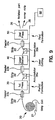
- An overall process apparatus schematic for this embodiment as well as other embodiments is depicted in Fig. 9. Initially, a strip 22 of sheet metal or other formable material is obtained in coil form 20 and for feeding into a first press 30 wherein the part is to be partially mechanically formed while still attached to strip 22.
- the strip used to form the rotary shaver cup in particular is preferably annealed medium carbon steel, although the process of the present invention may be used in general with low, medium or high carbon steel, or other metals and alloys in strip form.
- the coil of strip steel from which the part is to be made is first loaded into a payoff reel 21 and made ready to enter the feed in the first press.
- the feeder 23a which precedes the first die, precisely sets the lead or progression of the strip as it travels through the die. After entering the first progressive die, registration or pilot holes 27, for advancing the strip through the die, and part central holes 28 creating the inner diameter shape are pierced in strip 22 in the first station.
- the portion 29 of the strip around central hole 28 is thinned from its original trip thickness by cold reducing or hammering. This thickness reduction in area 29 is desirable for the central portion of the finished part which eventually forms the slotted comb portion of the shaver head, and will be omitted from subsequent views for clarity of other operations.
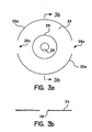
- the next die station in press 30 makes partial lance cuts 25a to substantially form flat blank 24 while uncut sections 26a retain blank 24 in strip 22 (Figs. 1, 3a and 3b). Additional lance cuts 25b with uncut sections 26b rotated 90° from uncut sections 26a are then formed (Fig. 1), so that part blank 24 remains connected to strip 22.
- a subsequent die station in press 30 draws a central concave depression 27 downward (Figs 1, 4a and 4b). Additional lanced cuts 25c again rotated 90° are added outside cuts 25b, leaving uncut sections 26c.
- the partially mechanically formed part 24 begins to shrink in diameter but still remains connected to strip 22 by a connecting web formed by lanced cuts 25a, 25b, 25c and uncut sections 26a, 26b, 26c.
- This connecting web remains to connect the partially formed part to strip 22 throughout the processing until the final die station in the second press, as discussed further below.
- a second draw upward creates what will be the top outer form 31 of rotary shaver part 24 (Figs. 1, 5a and 5b). It is to be understood that the part forming operations described above are progressive and sequential.
- the continuous strip of partially formed parts then leaves the first press, travels through a delay loop in accumulator 35a and then enters a second feeder 23b before entering a multi-head laser machining station 40.
- the laser is capable of creating a burr free through hole and with precise geometry and tight slot width by controlling the width of the laser beam.
- the laser obtains its orientation to the cup from registration holes 27 in the strip to which the cup is attached.
- the laser machining station may have as many laser beam emitting heads as needed coupled in series to create repetitive cutting depending on the number of cups in the strip progression. As the series of parts 24 and strip 22 is fed into laser station 40, a laser beam performs the desired machining operation.
- the laser cuts a series of slots in thinned section 29 to create a series of slots 32, 34 (Figs. 6a, 6b).
- Slots 32 extend radially outward in a somewhat curved fashion along an inner annular portion of part 24 while slots 34 also extend outward in a similarly curved fashion, in the same direction as slots 32, in an outer annular portion of part 24.
- These slots 32, 34 permit the hairs on the user's skin to pass through the shaver cup and be cut by a cutting blade mounted within the cup.
- the remaining metal portions between these slots create the stationary counterblades against which the rotary cutting blade pinches and trims the hairs.
- This slotted portion of the shaver head is also called the comb portion.
- the curved, non-linear slots which create the curved comb portion permits improved cutting geometry of the shaver head.
- the clockwise circular pattern of comb slots enhances whisker entry into the cut zone and permits tall or standing curled whisker hairs into the screen cup.
- the actual slot width is not dictated by any particular cutting saw parameters as in the prior art, but simply by the width and thermal column of the laser beam, thereby creating any size comb slot needed for any beard condition.
- the strip and partially laser machined formed parts After exiting the iaser station, the strip and partially laser machined formed parts enters a second delay loop accumulator 35b and feeder 23c prior to entering the second press 50 (Fig. 9). Both the first and second delay loops 35a, 35b and feeders 23a, 23b, 23c are useful to correct small irregularities in feed timing to ensure continuous function of presses 30 and 50 and laser station 40.
- Computer 60 is connected to and controls all of the machining stations 30, 40, 50, accumulators 35a, 35b and feeders 23a, 23b, 23c, and any other mechanical systems used in processing the present invention.
- this finish forming comprises one or more die stations in press 50 which continues the drawing of the part 24 to a deeper draw, without interfering or reforming the portions of the cup which have been laser machined.
- the series of draw stations establishes the final elevation and outer diameter of the cup.
- the die system first engages the existing laser machined comb portion below the demarcation area of the first draw. By capturing the first draw comb portion before the second draw station is engaged, the comb portion of the cup is securely isolated from any distortion.
- a double bend 33 is created at the periphery of part 24 to create additional hoop strength or stiffening to the part (Figs. 2, 7a and 7b).
- the cup is then drawn to its final elevation and is carried to a pinch trim station where it is blanked through the die and severed from the strip becoming a separate piece 36 (Fig. 2, 8a and 8b).
- the remaining strip 22, minus the formed parts, continues to a scrap chopper which creates the scrap strip 38 which is ejected from the press and then removed for proper disposal.
- the finished formed rotary shaver cup 36 may then be further processed as desired.
- a lapping operation may be performed to reduce the thickness of the cut comb section of the shaver.
- rotary lapping of the cup face may decrease the thickness of the strip from an initial thickness of 0.20 mm (0.008 inches) to a final thickness of 0.08 - 0.117 mm (0.0032-0.0046 inches).
- part 36 may then be pressure washed and a nickel plating applied, for example, with a thickness of 0.15 mm (0.006 inches).
- the process of the present invention may utilize an engraving laser machining process to mark additional features on the product.
- This laser engraving may be used with or without other laser machining for other parts for example identification plates.
- This may be accomplished as shown in Fig. 10 by starting with a strip 70, such as aluminum or steel, which may be supplied in coil form and continuously coated with a plurality of different color paints or coatings, such as three sequential layers 74, 76, 78.
- a first press includes one or more dies for piercing holes and forming a border bead 72 in the coated strip 70.
- the strip then enters the laser station where a laser beam etches or burns through the coating layers to different depths to expose different color layers, for example, two layer etching 80 to expose color layer 74 or single layer etching 82 to expose different color layer 76.
- desired characters or symbols of colors 74 and 76 are created on color background 78.
- the laser machining station will be able to keep up with the high speed mechanical forming operations.
- a subsequent press would then cut the finished part from the strip along edge 84.
- the first machining station 30 comprises a pilot hole cutting station, preferably utilizing a press to mechanically form the pilot hole.
- First laser station 40a preferably is the primary laser cutting station, and there is further provided a second laser cutting station 40b.
- Feeder stations 23b, 23c are associated with laser stations 40a, 40b, respectively. The remaining apparatus is as described in connection with Fig. 9.
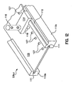
- feeder stations 23b, 23c preferably include a pair of guide rails 110a, 110b which each have a guide slot or notch 111 which receives the edges of strip 122.
- Pilot holes 127 have been previously formed in strip 122, preferably in first press 30 by the process previously described.
- a pilot air cylinder body 116 with air inlets and outlets for connection to a source of pressurized air is mounted on a pilot guide block 114, which extends outward over the strip in the y-direction and is slidable longitudinally in the x-direction of the strip in guide track 112 at the top of guide rail 110a.
- pilot pin 118 Extending from below pilot cylinder 116 is pilot pin 118 which moves upward and downward in the z-direction and is configured to be received within strip pilot holes 127 in sequential fashion. Initially, the strip will typically be manually threaded into and through guide slots 111 and into feeder assembly 23b or 23c. A signal is then sent to the microprocessor-based controller (PC) and the pilot pin is retracted in an up position into the cylinder and disengaged out of the strip holes, which is then signaled to the PC. The servo-controlled feeder feeds the strip a specified length equal to a multiple of the pilot hole 127 distance or pitch and sends a signal to the PC, whereupon pilot pin 118 is brought down and engaged within a particular pilot hole 127.
- PC microprocessor-based controller
- pilot pin 118 is tapered so that if there is a minor mis-registration between the pin and the pilot hole, the entry of the tapered segment within the pilot hole will cause the strip to shift to the correct position.
- the strip is locked and a signal is sent to the PC, which then initiates the laser machining.
- the position of the pilot pin within the cylinder body is determined by a magnetic sensor read switch, which generates the respective engaged and disengaged position signals.
- the pilot pin moves upward, the signal is sent to the PC and the servo feeds the strip a specific feed length, whereupon the process begins again.
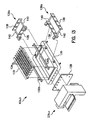
- Laser machining stations 40a, 40b are depicted in exploded view in Fig. 13 and receiving the strip 122 in Fig. 14.
- the feeder stations 23b, 23c may be connected to the respective iaser machining stations 48a, 40b by mounting plate 128.
- Each laser machining station includes an open rectangular frame 130 which receives a work platform 132 which is made up of a plurality of pointed supporting teeth 134 which support the sheet at individual, mutually spaced points. This permits through-laser cutting with a minimum of disruption to the work platform. Of course, at some point the work platform will become excessively damaged by such through-laser machining and will have to be replaced.
- tandem servos e.g. two feeders, may maintain tension on either side of the laser machining station during the laser machining process.
- an outrigger holding arm assembly 136a which comprises members 138 extending in the y-direction connected by members 140 extending in the x-direction and secured by brackets to frame 130. This extends the effective support length of frame 130. If individual, discontinuous sheets of width wider than the feeder are cut using the laser-machining station 40a, 40b, a further side outrigger assembly 136b may be employed utilizing members 138 extending in the x-direction connected by members 140 extending in the y-direction and connected by brackets to frame 130. A pair of laser heads 115a, 115b (Fig. 14) are suspended over the laser machining frame 130 and strip by supporting arm 148, which also connects to frame 130.
- a yttrium/aluminum/garnet (YAG) or other suitable laser is contained in laser power supply 151, and delivers the laser light through fiber optic cable 117 to laser heads 115a, b.
- a microprocessor based x-y controller which may be contained in computer 60 (Fig. 11), controls and directs movement of the laser heads and arm over strip 122 in the desired pattern to laser machine the parts.
- a first laser station may make a partial laser machining of a part 150 which extensively cuts or otherwise laser machines the part, but still permits the part to be retained within and held by the remainder of strip 122.
- finished laser cuts 152 extend around the inner and outer peripheries of the part 150 except at tab sections 154 which remain uncut and provide the connection to and support by the remainder of strip 122.
- the laser machining may be completed by cutting tabs 154 along the outer and inner periphery of part 150, resulting in a final part configuration (Fig. 16) which is separated from the remainder of strip 122 and consists entirely of laser-cut openings and edges.
- some openings or edges on the part may be press formed or cut by first press 30.
- a conventional knock out arm (not shown) may assist in dropping or otherwise separating part 150 from the remainder of strip 122. The remainder of strip 122 may be then discarded to scrap while the finished parts 150 are stored (Fig. 11).
- this example may employ a single laser machining station having one, two or more laser heads for laser machining the strip.
- the strip into the laser station and the laser is brought into a first position with respect to the strip.
- the laser machines substantially all of the outline of the parts in sequence along the strip, leaving at least one tab portion connecting each part to the strip.
- the laser is then brought into a different, second position, downstream or further along the strip, where it laser machines the tab portions connecting the parts to the strip in sequence along the strip, thereby separating the laser machined parts from remaining portions of the strip.
- the lasers may move simultaneously in the same direction with respect to the strip, but each over different portions of the strip, during the laser machining.
- a first laser will laser machine fresh strip to create substantially all of the outline of the parts, leaving at least one tab portion connecting each part to the strip, while a second laser will laser machine the tab portions connecting the parts to the strip to separate the parts from the strip.
- the same x-y controller directs and control both lasers.
- the strip feeder advances the strip so that the partial laser machining created by the first laser (Fig. 15) is below the second laser, and fresh strip is below the first laser. The cycle is then repeated.
- the present invention may be integrated with existing manufacturing systems which utilize one or more die stations to mechanically form a part both before and after the laser machining stage.
- the process is achieved in continuous strip format resulting in progressive part manufacturing that has considerable advantages over individual part handling used prior for laser machining parts.
Landscapes
- Physics & Mathematics (AREA)
- Optics & Photonics (AREA)
- Engineering & Computer Science (AREA)
- Plasma & Fusion (AREA)
- Mechanical Engineering (AREA)
- Laser Beam Processing (AREA)
- Numerical Control (AREA)
Claims (18)
- Procédé pour la fabrication de pièces (36) à partir d'un métal en bande (22), comprenant:la fourniture d'une bande (22) de métal à partir de laquelle des pièces (36) sont à fabriquer;la formation mécanique partielle d'une pluralité de pièces dans une portion de la bande de métal (22);l'usinage au laser des pièces formées mécaniquement partiellement tout en étant dans ladite bande de métal (22);la formation mécanique supplémentaire des pièces formées mécaniquement partiellement, usinées au laser tout en étant dans la bande de métal (22); etla séparation des pièces usinées au laser, formées mécaniquement davantage (36) des portions restantes de ladite bande de métal (22).
- Procédé suivant la revendication 1, dans lequel l'étape de formation mécanique partielle inclut l'introduction de la bande de métal (22) dans une presse (30) pour former mécaniquement partiellement les pièces.
- Procédé suivant la revendication 1 ou 2, dans lequel l'étape d'usinage au laser inclut l'introduction de la bande de métal (22) dans une station d'usinage au laser (40) pour usiner au laser les pièces.
- Procédé suivant l'une quelconque des revendications 1 à 3, dans lequel l'étape de formation mécanique supplémentaire inclut l'introduction de la bande de métal (22) dans une presse (50) pour former mécaniquement davantage les pièces.
- Procédé suivant l'une quelconque des revendications 1 à 4, dans lequel l'étape de formation mécanique partielle comprend l'étirage partiel des pièces.
- Procédé suivant l'une quelconque des revendications 1 à 5, dans lequel l'étape d'usinage au laser comprend l'usinage au laser de trous dans les pièces.
- Procédé suivant l'une quelconque des revendications 1 à 5, dans lequel l'étape d'usinage au laser comprend le décapage au laser des pièces.
- Procédé suivant l'une quelconque des revendications 1 à 7, dans lequel l'étape de formation mécanique supplémentaire comprend l'étirage final des pièces.
- Procédé suivant l'une quelconque des revendications 1 à 8, dans lequel les étapes sont effectuées en continu et par séquences.
- Procédé suivant l'une quelconque des revendications 1 à 9, incluant en outre l'accumulation de la bande de métal (22) dans un accumulateur (35a, 35b) pour réguler les différences de vitesse de procédé entre l'étape de formation mécanique partielle et l'étape d'usinage au laser ou entre l'étape d'usinage au laser et l'étape de formation mécanique supplémentaire.
- Procédé suivant l'une quelconque des revendications 1 à 10, incluant la fourniture de la bande de métal (22) sous une forme embobinée et dans lequel les étapes suivant la formation mécanique partielle d'une pluralité de pièces sont effectuées sans rembobinage de la bande de métal (22).
- Procédé suivant l'une quelconque des revendications 1 à 11, dans lequel l'étape de formation mécanique partielle de la pluralité de pièces comprend l'étirage partiel d'une pluralité de godets de rasoir dans une portion de la bande de métal (22).
- Procédé suivant la revendication 12, dans lequel l'étape d'usinage au laser des pièces formées mécaniquement partiellement comprend l'usinage au laser de fentes (32, 34) dans lesdits godets de rasoir dans ladite bande de métal.
- Procédé suivant la revendication 12, dans lequel l'étape d'usinage au laser des pièces formées mécaniquement partiellement comprend l'usinage au laser de fentes curvilignes (32, 34) dans lesdits godets de rasoir dans ladite bande de métal (22).
- Procédé suivant l'une quelconque des revendications 12 à 14, dans lequel l'étape de formation mécanique supplémentaire des pièces formées mécaniquement partiellement, usinées au laser comprend l'étirage final d'une pluralité desdits godets de rasoir dans ladite bande de métal.
- Appareil (20) pour la fabrication de pièces à partir d'un métal en bande, comprenant:un dérouleur (21) adapté pour dérouler une bande (22) de métal à partir de laquelle des pièces (36) sont à fabriquer;une première presse (30) adaptée pour former mécaniquement partiellement une pluralité de pièces dans une portion de la bande de métal (22);une station d'usinage au laser (40) adaptée pour usiner au laser les pièces formées mécaniquement partiellement tout en étant dans ladite bande de métal (22); etune deuxième presse (50) adaptée pour former mécaniquement davantage les pièces formées mécaniquement partiellement, usinées au laser tout en étant dans ladite bande de métal (22).
- Appareil suivant la revendication 16, dans lequel la deuxième presse (50) est en outre adaptée pour séparer les pièces usinées au laser, formées mécaniquement davantage (36) des portions restantes de ladite bande de métal (22).
- Appareil suivant la revendication 16 ou 17, incluant en outre un accumulateur de bande de métal (35a) entre la première presse (30) et la station d'usinage au laser (40) adapté pour réguler les différences de vitesse de procédé entre la première presse (30) et la station d'usinage au laser (40).
Applications Claiming Priority (3)
| Application Number | Priority Date | Filing Date | Title |
|---|---|---|---|
| US695468 | 2000-10-24 | ||
| US09/695,468 US6515256B1 (en) | 2000-04-13 | 2000-10-24 | Process for laser machining continuous metal strip |
| PCT/US2001/018289 WO2002034454A1 (fr) | 2000-10-24 | 2001-06-05 | Procede d'usinage laser de bande metallique continue |
Publications (3)
| Publication Number | Publication Date |
|---|---|
| EP1328371A1 EP1328371A1 (fr) | 2003-07-23 |
| EP1328371A4 EP1328371A4 (fr) | 2004-10-20 |
| EP1328371B1 true EP1328371B1 (fr) | 2006-08-02 |
Family
ID=24793096
Family Applications (1)
| Application Number | Title | Priority Date | Filing Date |
|---|---|---|---|
| EP01944309A Expired - Lifetime EP1328371B1 (fr) | 2000-10-24 | 2001-06-05 | Procede et appareil pour realiser des pieces a partir bande metallique continue, utilisant une machine laser |
Country Status (8)
| Country | Link |
|---|---|
| US (2) | US6515256B1 (fr) |
| EP (1) | EP1328371B1 (fr) |
| JP (1) | JP2004512179A (fr) |
| CN (1) | CN1269614C (fr) |
| AT (1) | ATE334773T1 (fr) |
| AU (1) | AU2001266734A1 (fr) |
| DE (1) | DE60121982T2 (fr) |
| WO (1) | WO2002034454A1 (fr) |
Cited By (1)
| Publication number | Priority date | Publication date | Assignee | Title |
|---|---|---|---|---|
| CN111098047A (zh) * | 2019-12-17 | 2020-05-05 | 中国电子科技集团公司第十三研究所 | 陶瓷生带料切割设备用的带料传输装置 |
Families Citing this family (44)
| Publication number | Priority date | Publication date | Assignee | Title |
|---|---|---|---|---|
| DE19853366B4 (de) * | 1998-11-19 | 2007-07-19 | Schuler Pressen Gmbh & Co. Kg | Vorrichtung und Verfahren zum Umformen |
| DE10322928B3 (de) * | 2003-05-21 | 2004-10-21 | Thyssenkrupp Automotive Ag | Verfahren zum Herstellen von Formbauteilen |
| DE10352402B4 (de) * | 2003-11-10 | 2015-12-17 | Lasertec Gmbh | Laserbearbeitungsmaschine und Laserbearbeitungsverfahren |
| EP1591547B1 (fr) * | 2004-04-27 | 2007-12-26 | Hitachi Metals, Ltd. | Bande d'acier pour remplacement de lame et méthode de production |
| US8037613B2 (en) | 2004-09-02 | 2011-10-18 | Rovcal, Inc. | Shaving head for rotary shaver and method of manufacturing the same |
| US7866033B2 (en) * | 2004-09-29 | 2011-01-11 | Ged Integrated Solutions, Inc. | Window component system including pusher for scrap removal |
| US8151467B2 (en) * | 2004-11-01 | 2012-04-10 | Koninklijke Philips Electronics N.V. | Cutter member for a rotary shaver, method for making such a member and rotary shaver provided therewith |
| EP1819488B1 (fr) * | 2004-11-01 | 2017-01-04 | Koninklijke Philips N.V. | Unite de coupe destinee a un rasoir rotatif et rasoir rotatif pourvu d'une telle unite de coupe |
| ATE392981T1 (de) * | 2005-01-25 | 2008-05-15 | Bystronic Laser Ag | Verfahren zum laserschneiden von rohblechen und laserschneidemaschine zur durchführung des verfahrens |
| US7600527B2 (en) | 2005-04-01 | 2009-10-13 | Fike Corporation | Reverse acting rupture disc with laser-defined electropolished line of weakness and method of forming the line of weakness |
| JP2007253287A (ja) * | 2006-03-24 | 2007-10-04 | Yamazaki Mazak Corp | 3次元形状を有する板金製品の製造方法及び製品 |
| WO2008048808A2 (fr) * | 2006-10-06 | 2008-04-24 | Applied Medical Resources Corporation | Procédé de fabrication d'un stylet à aiguille pour une insufflation à débit élevé |
| DE102007062784A1 (de) * | 2007-03-03 | 2008-09-04 | Faurecia Autositze Gmbh | Verfahren zum Herstellen eines Lagerbolzen-Bauteils |
| WO2009077987A1 (fr) * | 2007-12-17 | 2009-06-25 | Koninklijke Philips Electronics N.V. | Procédé d'inclusion d'éléments dans un article fabriqué à partir d'acier inoxydable à trempe secondaire martensitique |
| US8931322B2 (en) * | 2008-06-25 | 2015-01-13 | Adc Telecommunications, Inc. | Coil handling system and method |
| CN102216025B (zh) * | 2008-11-18 | 2015-04-08 | 乔治洛德方法研究和开发液化空气有限公司 | 用于高速激光冲裁的支承台架 |
| MX2011013327A (es) * | 2009-06-09 | 2012-02-28 | Shiloh Ind Inc | Aparato, sistema y metodo para fabricar partes de metal. |
| EP2519761A4 (fr) * | 2009-12-29 | 2016-05-04 | Saint Gobain Performance Plast | Ressorts et procédés pour les former |
| CN102632368A (zh) * | 2012-04-26 | 2012-08-15 | 昆山嘉升精密电子工业有限公司 | 冲压线自动攻牙制程及其加工系统 |
| US20130319066A1 (en) * | 2012-06-04 | 2013-12-05 | Jefferey W. Bennett | Manufacturing System and Process Using a Laser Assisted Stamping Die |
| US9007413B2 (en) * | 2012-08-13 | 2015-04-14 | Crown Packaging Technology, Inc. | Laser marking system and method |
| BR112015023960B1 (pt) * | 2013-03-22 | 2020-12-01 | Koninklijke Philips N.V | unidade de corte e aparelho para barbeamento ou depilação |
| CN103394916B (zh) * | 2013-08-07 | 2016-03-02 | 吴振泉 | 采用激光切割技术的开卷落料生产设备及加工方法 |
| DE102013020662B4 (de) * | 2013-12-06 | 2026-01-08 | Feintool International Holding Ag | Verfahren zur Herstellung von Lamellen für ein Lamellenpaket, insbesondere für elektrische Maschinen und Generatoren, Vorrichtung mit wenigstens einer Stanzpresse sowie nach dem Verfahren hergestellte Lamelle und Lamellenpaket |
| US10211443B2 (en) | 2014-09-10 | 2019-02-19 | Cellink Corporation | Battery interconnects |
| US20180093348A1 (en) * | 2016-03-25 | 2018-04-05 | Mitsubishi Electric Corporation | Laser beam machine, machining facility, setting apparatus, program and setting method |
| IE86890B1 (en) * | 2016-06-24 | 2018-04-04 | Severn Innovation Ltd | Foil for an electric razor and an electric razor comprising such a foil |
| US11116070B2 (en) | 2017-07-13 | 2021-09-07 | Cellink Corporation | Interconnect circuit methods and devices |
| CN109954784A (zh) * | 2017-12-25 | 2019-07-02 | 鸿富锦精密工业(武汉)有限公司 | 共模冲压设备及共模冲压方法 |
| JP7456935B2 (ja) * | 2018-04-13 | 2024-03-27 | アイピージー フォトニクス コーポレーション | シート材料のレーザー支援機械加工 |
| WO2019202930A1 (fr) * | 2018-04-20 | 2019-10-24 | 日本電産株式会社 | Dispositif de fabrication d'un produit pressé |
| CN108838525A (zh) * | 2018-07-25 | 2018-11-20 | 杨晟 | 手提式水下钢缆激光切割系统及使用方法 |
| CN113228831A (zh) | 2018-10-29 | 2021-08-06 | 塞林克公司 | 柔性混合互连电路 |
| US10842025B1 (en) * | 2019-09-20 | 2020-11-17 | Manaflex Llc | Reel-to-reel slug removal methods and devices in FPC fabrication |
| EP3804960A1 (fr) * | 2019-10-11 | 2021-04-14 | WM Thermoforming Machines SA | Procédé et machine de thermoformage |
| KR20230074582A (ko) | 2020-10-02 | 2023-05-30 | 셀링크 코포레이션 | 가요성 상호 연결 회로에 대한 연결 형성 |
| CN116325377B (zh) | 2020-10-02 | 2024-07-02 | 塞林克公司 | 用于连接柔性互连电路的方法和系统 |
| KR20230160239A (ko) | 2021-03-24 | 2023-11-23 | 셀링크 코포레이션 | 다층 가요성 배터리 인터커넥트 및 이의 제조 방법 |
| JP7599041B2 (ja) * | 2021-04-28 | 2024-12-12 | サン-ゴバン パフォーマンス プラスティックス コーポレイション | 半径方向に切断されたトーラスばねを有する封止部 |
| CN113231517A (zh) * | 2021-05-20 | 2021-08-10 | 江苏信息职业技术学院 | 一种卷料储料串级进给速度控制方法 |
| EP4442087A1 (fr) | 2022-02-22 | 2024-10-09 | Cellink Corporation | Circuits d'interconnexion flexibles et leurs procédés de fabrication |
| US11950377B1 (en) | 2022-04-15 | 2024-04-02 | Cellink Corporation | Flexible interconnect circuits for battery packs |
| FR3139868B1 (fr) * | 2022-09-16 | 2024-08-23 | Gaztransport Et Technigaz | Bande d’ancrage et procédé de fabrication d’une telle bande d’ancrage |
| US12362437B2 (en) | 2023-11-13 | 2025-07-15 | Cellink Corporation | Multilayered flexible interconnect circuits for battery assemblies and methods of fabricating and installing thereof |
Family Cites Families (44)
| Publication number | Priority date | Publication date | Assignee | Title |
|---|---|---|---|---|
| US1151983A (en) | 1914-04-20 | 1915-08-31 | Amanda Cummins Winfield | Method of making metal barrels and kegs. |
| US3226527A (en) | 1963-10-23 | 1965-12-28 | William H Harding | Apparatus for perforating sheet material |
| US3256524A (en) | 1963-11-29 | 1966-06-14 | Honeywell Inc | Laser recording apparatus |
| US3422246A (en) * | 1965-08-18 | 1969-01-14 | Kearney & Trecker Corp | Laser cutting machine tool |
| GB1474505A (fr) | 1974-12-16 | 1977-05-25 | ||
| US3932967A (en) | 1975-05-07 | 1976-01-20 | Hanes Donald M | Sharpener for rotary electric razor |
| US4180906A (en) | 1977-10-31 | 1980-01-01 | May Russell P | Razor with orbiting discs with sharp-edge slots, and method for making discs |
| US4182084A (en) | 1978-05-02 | 1980-01-08 | Friedenberg Richard C | Blade sharpener |
| US4285754A (en) * | 1979-11-05 | 1981-08-25 | Solid Photography Inc. | Method and apparatus for producing planar elements in the construction of surfaces and bodies |
| US4301593A (en) | 1979-12-28 | 1981-11-24 | May Russell P | Anti-spin coupling for orbiting disc razor |
| US4328411A (en) | 1980-04-28 | 1982-05-04 | General Electric Company | Cutting amorphous metal by crystallization with a laser or electron beam |
| JPS5829598A (ja) * | 1981-08-12 | 1983-02-21 | Toshiba Corp | 順送プレス加工方法 |
| US4676586A (en) * | 1982-12-20 | 1987-06-30 | General Electric Company | Apparatus and method for performing laser material processing through a fiber optic |
| USD279825S (en) | 1983-01-31 | 1985-07-23 | Izumi Seimitsu Kogyo Kabushiki | Electric shaver |
| USD279509S (en) | 1983-03-02 | 1985-07-02 | Matsushita Electric Works, Ltd. | Electric shaver |
| USD284224S (en) | 1984-03-29 | 1986-06-10 | Izumi Seimitsu Kogyo Kabushiki Kaisha | Electric shaver |
| US4707073A (en) | 1985-09-04 | 1987-11-17 | Raytheon Company | Fiber optic beam delivery system for high-power laser |
| JPS63165091A (ja) * | 1986-12-26 | 1988-07-08 | Sanoyasu:Kk | 穴の連続加工方法および装置 |
| US4782208A (en) | 1987-06-01 | 1988-11-01 | Withrow David A | Method and apparatus for slitting metal strips |
| US5089062A (en) | 1988-10-14 | 1992-02-18 | Abb Power T&D Company, Inc. | Drilling of steel sheet |
| US5058413A (en) | 1989-11-07 | 1991-10-22 | Robert Muddiman | Rupture disc |
| JPH03216220A (ja) * | 1990-01-19 | 1991-09-24 | Amada Co Ltd | 複合加工機 |
| FR2657552B1 (fr) * | 1990-01-30 | 1994-10-21 | Elf Aquitaine | Procede et dispositif de decoupe d'un ensemble multicouche constitue d'une pluralite de couches minces. |
| DE4128194C2 (de) | 1991-08-24 | 1994-05-19 | Rohde & Schwarz | Vorrichtung zum automatischen Herstellen von Blechteilen |
| GB9207054D0 (en) | 1992-03-31 | 1992-05-13 | Gillette Co | Methods of manufacturing perforated foils |
| JPH06142995A (ja) | 1992-10-28 | 1994-05-24 | Oki Electric Ind Co Ltd | 板金部品の製造方法および製造システム |
| US5395028A (en) * | 1992-11-18 | 1995-03-07 | Sony Electronics, Inc. | Apparatus for transporting thin metal sheets longitudinally with transverse tension |
| USD356184S (en) | 1993-05-05 | 1995-03-07 | Izumi Products Company | Electric shaver |
| JPH06328276A (ja) * | 1993-05-25 | 1994-11-29 | Toshiba Corp | レーザ加工装置 |
| US5511920A (en) * | 1993-10-14 | 1996-04-30 | Artrip; Donald | System and method for use when forming lift-tab can end assemblies |
| AT405145B (de) * | 1993-12-17 | 1999-05-25 | Felsner Franz | Anordnung und verfahren zur spanlosen bearbeitung von material oder werkstücken |
| DE4435532A1 (de) | 1994-10-05 | 1996-04-11 | Mann & Hummel Filter | Verfahren zur Herstellung von Filtern |
| DE4442137C2 (de) | 1994-11-26 | 1997-04-03 | Herbert Gegenheimer | Modular erweiterbare, dreidimensional verstellbare Vorrichtung mit Greifern |
| US6183064B1 (en) | 1995-08-28 | 2001-02-06 | Lexmark International, Inc. | Method for singulating and attaching nozzle plates to printheads |
| JP3100337B2 (ja) | 1996-01-09 | 2000-10-16 | 江南特殊産業株式会社 | 多孔質電鋳殻及びその製造方法 |
| KR100479962B1 (ko) * | 1996-02-09 | 2005-05-16 | 어드밴스드 레이저 세퍼래이션 인터내셔널 비.브이. | 반도체소자분리방법 |
| JP3638726B2 (ja) * | 1996-07-18 | 2005-04-13 | 株式会社アマダ | 複合加工装置 |
| JPH10156570A (ja) * | 1996-11-20 | 1998-06-16 | Ibiden Co Ltd | レーザ加工装置、多層プリント配線板の製造装置及び製造方法 |
| US5908664A (en) * | 1997-04-25 | 1999-06-01 | Nagayama Electronic Industry Co., Ltd. | Method of working metal member |
| IT1292330B1 (it) * | 1997-05-27 | 1999-01-29 | Crea Srl | Procedimento per la produzione di pezzi di lamiera piegati |
| JP3642930B2 (ja) * | 1997-08-25 | 2005-04-27 | 松下電器産業株式会社 | 複数軸レーザ加工方法およびその装置 |
| US6031199A (en) * | 1997-10-28 | 2000-02-29 | Worthington Machine Technology | Combination laser cutting and blank welding apparatus and method |
| US6080958A (en) * | 1998-07-16 | 2000-06-27 | Ball Corporation | Method and apparatus for marking containers using laser light |
| JP3895054B2 (ja) * | 1998-08-19 | 2007-03-22 | 株式会社小松製作所 | トランスファプレス機におけるトランスファフィーダの3次元駆動装置 |
-
2000
- 2000-10-24 US US09/695,468 patent/US6515256B1/en not_active Expired - Fee Related
-
2001
- 2001-06-05 DE DE60121982T patent/DE60121982T2/de not_active Expired - Lifetime
- 2001-06-05 AT AT01944309T patent/ATE334773T1/de not_active IP Right Cessation
- 2001-06-05 WO PCT/US2001/018289 patent/WO2002034454A1/fr not_active Ceased
- 2001-06-05 AU AU2001266734A patent/AU2001266734A1/en not_active Abandoned
- 2001-06-05 JP JP2002537485A patent/JP2004512179A/ja active Pending
- 2001-06-05 CN CN01817913.4A patent/CN1269614C/zh not_active Expired - Fee Related
- 2001-06-05 EP EP01944309A patent/EP1328371B1/fr not_active Expired - Lifetime
-
2002
- 2002-12-12 US US10/318,310 patent/US6881923B2/en not_active Expired - Fee Related
Cited By (1)
| Publication number | Priority date | Publication date | Assignee | Title |
|---|---|---|---|---|
| CN111098047A (zh) * | 2019-12-17 | 2020-05-05 | 中国电子科技集团公司第十三研究所 | 陶瓷生带料切割设备用的带料传输装置 |
Also Published As
| Publication number | Publication date |
|---|---|
| EP1328371A4 (fr) | 2004-10-20 |
| DE60121982T2 (de) | 2007-07-26 |
| WO2002034454A1 (fr) | 2002-05-02 |
| EP1328371A1 (fr) | 2003-07-23 |
| CN1269614C (zh) | 2006-08-16 |
| AU2001266734A1 (en) | 2002-05-06 |
| US20030116543A1 (en) | 2003-06-26 |
| US6881923B2 (en) | 2005-04-19 |
| DE60121982D1 (de) | 2006-09-14 |
| US6515256B1 (en) | 2003-02-04 |
| ATE334773T1 (de) | 2006-08-15 |
| CN1471449A (zh) | 2004-01-28 |
| JP2004512179A (ja) | 2004-04-22 |
Similar Documents
| Publication | Publication Date | Title |
|---|---|---|
| EP1328371B1 (fr) | Procede et appareil pour realiser des pieces a partir bande metallique continue, utilisant une machine laser | |
| US8471175B2 (en) | Laser blanking from coil strip profile conveyor system | |
| EP2285521B1 (fr) | Dispositif de découpage progressif par laser pour découpe à grande vitesse | |
| US6515253B1 (en) | Process for laser machining continuous metal stamped strip | |
| AU698895B2 (en) | Razor blade manufacture | |
| US5609075A (en) | Razor blade manufacture | |
| US4773293A (en) | Method of and apparatus for manufacturing liner for magnetic disk | |
| PL172278B1 (pl) | Sposób i urzadzenie do wytwarzania czesci z blachy PL | |
| HK188995A (en) | Split ring springs for snap fasteners and method of manufacturing the same | |
| US3854355A (en) | Method of punching sheet segments having substantially annular sector shape | |
| KR102729907B1 (ko) | 차량용 모터의 헤어핀 제조방법 | |
| US6408670B1 (en) | Carrierless progressive die system | |
| US7578217B2 (en) | Manufacturing razor blades | |
| AU701377B2 (en) | Razor blade manufacture | |
| US4744275A (en) | Method of and apparatus for processing strip | |
| EP0514099B1 (fr) | Dispositif de découpage et procédé | |
| SU1368112A1 (ru) | Способ получени полосового материала | |
| JP3844530B2 (ja) | スロッティング加工方法 | |
| JPS63130227A (ja) | プレスによる追切り加工方法および装置 | |
| JPS61103607A (ja) | 圧延材の接合方法 | |
| SU1593741A1 (ru) | Способ малоотходной последовательной штамповки и штамп дл его осуществлени | |
| JPS6123502A (ja) | 圧延材連結方法 | |
| JPH05169153A (ja) | 加工材料の縁さんの補強方法 | |
| JPS62142003A (ja) | 圧延設備 | |
| JP2001071002A (ja) | 連続圧延における後行材の速度制御方法 |
Legal Events
| Date | Code | Title | Description |
|---|---|---|---|
| PUAI | Public reference made under article 153(3) epc to a published international application that has entered the european phase |
Free format text: ORIGINAL CODE: 0009012 |
|
| 17P | Request for examination filed |
Effective date: 20030327 |
|
| AK | Designated contracting states |
Designated state(s): AT BE CH CY DE DK ES FI FR GB GR IE IT LI LU MC NL PT SE TR |
|
| AX | Request for extension of the european patent |
Extension state: AL LT LV MK RO SI |
|
| RIC1 | Information provided on ipc code assigned before grant |
Ipc: 7B 23K 26/08 B Ipc: 7B 23K 26/38 A Ipc: 7B 21D 28/10 B Ipc: 7B 21D 22/20 B Ipc: 7B 23K 26/42 B |
|
| A4 | Supplementary search report drawn up and despatched |
Effective date: 20040902 |
|
| 17Q | First examination report despatched |
Effective date: 20050630 |
|
| GRAP | Despatch of communication of intention to grant a patent |
Free format text: ORIGINAL CODE: EPIDOSNIGR1 |
|
| RTI1 | Title (correction) |
Free format text: PROCESS AND APPARATUS FOR MAKING PARTS FROM A CONTINUOUS METAL STRIP, WITH USE OF LASER MACHINING DEVICE |
|
| GRAS | Grant fee paid |
Free format text: ORIGINAL CODE: EPIDOSNIGR3 |
|
| GRAA | (expected) grant |
Free format text: ORIGINAL CODE: 0009210 |
|
| AK | Designated contracting states |
Kind code of ref document: B1 Designated state(s): AT BE CH CY DE DK ES FI FR GB GR IE IT LI LU MC NL PT SE TR |
|
| PG25 | Lapsed in a contracting state [announced via postgrant information from national office to epo] |
Ref country code: IT Free format text: LAPSE BECAUSE OF FAILURE TO SUBMIT A TRANSLATION OF THE DESCRIPTION OR TO PAY THE FEE WITHIN THE PRESCRIBED TIME-LIMIT;WARNING: LAPSES OF ITALIAN PATENTS WITH EFFECTIVE DATE BEFORE 2007 MAY HAVE OCCURRED AT ANY TIME BEFORE 2007. THE CORRECT EFFECTIVE DATE MAY BE DIFFERENT FROM THE ONE RECORDED. Effective date: 20060802 Ref country code: BE Free format text: LAPSE BECAUSE OF FAILURE TO SUBMIT A TRANSLATION OF THE DESCRIPTION OR TO PAY THE FEE WITHIN THE PRESCRIBED TIME-LIMIT Effective date: 20060802 Ref country code: NL Free format text: LAPSE BECAUSE OF FAILURE TO SUBMIT A TRANSLATION OF THE DESCRIPTION OR TO PAY THE FEE WITHIN THE PRESCRIBED TIME-LIMIT Effective date: 20060802 Ref country code: LI Free format text: LAPSE BECAUSE OF FAILURE TO SUBMIT A TRANSLATION OF THE DESCRIPTION OR TO PAY THE FEE WITHIN THE PRESCRIBED TIME-LIMIT Effective date: 20060802 Ref country code: FI Free format text: LAPSE BECAUSE OF FAILURE TO SUBMIT A TRANSLATION OF THE DESCRIPTION OR TO PAY THE FEE WITHIN THE PRESCRIBED TIME-LIMIT Effective date: 20060802 Ref country code: CH Free format text: LAPSE BECAUSE OF FAILURE TO SUBMIT A TRANSLATION OF THE DESCRIPTION OR TO PAY THE FEE WITHIN THE PRESCRIBED TIME-LIMIT Effective date: 20060802 Ref country code: AT Free format text: LAPSE BECAUSE OF FAILURE TO SUBMIT A TRANSLATION OF THE DESCRIPTION OR TO PAY THE FEE WITHIN THE PRESCRIBED TIME-LIMIT Effective date: 20060802 |
|
| REG | Reference to a national code |
Ref country code: GB Ref legal event code: FG4D |
|
| REG | Reference to a national code |
Ref country code: CH Ref legal event code: EP |
|
| REG | Reference to a national code |
Ref country code: IE Ref legal event code: FG4D |
|
| REF | Corresponds to: |
Ref document number: 60121982 Country of ref document: DE Date of ref document: 20060914 Kind code of ref document: P |
|
| PG25 | Lapsed in a contracting state [announced via postgrant information from national office to epo] |
Ref country code: SE Free format text: LAPSE BECAUSE OF FAILURE TO SUBMIT A TRANSLATION OF THE DESCRIPTION OR TO PAY THE FEE WITHIN THE PRESCRIBED TIME-LIMIT Effective date: 20061102 Ref country code: DK Free format text: LAPSE BECAUSE OF FAILURE TO SUBMIT A TRANSLATION OF THE DESCRIPTION OR TO PAY THE FEE WITHIN THE PRESCRIBED TIME-LIMIT Effective date: 20061102 |
|
| PG25 | Lapsed in a contracting state [announced via postgrant information from national office to epo] |
Ref country code: ES Free format text: LAPSE BECAUSE OF FAILURE TO SUBMIT A TRANSLATION OF THE DESCRIPTION OR TO PAY THE FEE WITHIN THE PRESCRIBED TIME-LIMIT Effective date: 20061113 |
|
| NLV1 | Nl: lapsed or annulled due to failure to fulfill the requirements of art. 29p and 29m of the patents act | ||
| PG25 | Lapsed in a contracting state [announced via postgrant information from national office to epo] |
Ref country code: PT Free format text: LAPSE BECAUSE OF FAILURE TO SUBMIT A TRANSLATION OF THE DESCRIPTION OR TO PAY THE FEE WITHIN THE PRESCRIBED TIME-LIMIT Effective date: 20070102 |
|
| REG | Reference to a national code |
Ref country code: CH Ref legal event code: PL |
|
| EN | Fr: translation not filed | ||
| PLBE | No opposition filed within time limit |
Free format text: ORIGINAL CODE: 0009261 |
|
| STAA | Information on the status of an ep patent application or granted ep patent |
Free format text: STATUS: NO OPPOSITION FILED WITHIN TIME LIMIT |
|
| 26N | No opposition filed |
Effective date: 20070503 |
|
| PG25 | Lapsed in a contracting state [announced via postgrant information from national office to epo] |
Ref country code: MC Free format text: LAPSE BECAUSE OF NON-PAYMENT OF DUE FEES Effective date: 20070630 |
|
| GBPC | Gb: european patent ceased through non-payment of renewal fee |
Effective date: 20070605 |
|
| PG25 | Lapsed in a contracting state [announced via postgrant information from national office to epo] |
Ref country code: GR Free format text: LAPSE BECAUSE OF FAILURE TO SUBMIT A TRANSLATION OF THE DESCRIPTION OR TO PAY THE FEE WITHIN THE PRESCRIBED TIME-LIMIT Effective date: 20061103 Ref country code: FR Free format text: LAPSE BECAUSE OF FAILURE TO SUBMIT A TRANSLATION OF THE DESCRIPTION OR TO PAY THE FEE WITHIN THE PRESCRIBED TIME-LIMIT Effective date: 20070511 |
|
| PG25 | Lapsed in a contracting state [announced via postgrant information from national office to epo] |
Ref country code: GB Free format text: LAPSE BECAUSE OF NON-PAYMENT OF DUE FEES Effective date: 20070605 Ref country code: IE Free format text: LAPSE BECAUSE OF NON-PAYMENT OF DUE FEES Effective date: 20070605 |
|
| PG25 | Lapsed in a contracting state [announced via postgrant information from national office to epo] |
Ref country code: FR Free format text: LAPSE BECAUSE OF FAILURE TO SUBMIT A TRANSLATION OF THE DESCRIPTION OR TO PAY THE FEE WITHIN THE PRESCRIBED TIME-LIMIT Effective date: 20060802 |
|
| PG25 | Lapsed in a contracting state [announced via postgrant information from national office to epo] |
Ref country code: CY Free format text: LAPSE BECAUSE OF FAILURE TO SUBMIT A TRANSLATION OF THE DESCRIPTION OR TO PAY THE FEE WITHIN THE PRESCRIBED TIME-LIMIT Effective date: 20060802 Ref country code: LU Free format text: LAPSE BECAUSE OF NON-PAYMENT OF DUE FEES Effective date: 20070605 |
|
| PG25 | Lapsed in a contracting state [announced via postgrant information from national office to epo] |
Ref country code: TR Free format text: LAPSE BECAUSE OF FAILURE TO SUBMIT A TRANSLATION OF THE DESCRIPTION OR TO PAY THE FEE WITHIN THE PRESCRIBED TIME-LIMIT Effective date: 20060802 |
|
| PGFP | Annual fee paid to national office [announced via postgrant information from national office to epo] |
Ref country code: DE Payment date: 20100602 Year of fee payment: 10 |
|
| REG | Reference to a national code |
Ref country code: DE Ref legal event code: R119 Ref document number: 60121982 Country of ref document: DE Effective date: 20120103 |
|
| PG25 | Lapsed in a contracting state [announced via postgrant information from national office to epo] |
Ref country code: DE Free format text: LAPSE BECAUSE OF NON-PAYMENT OF DUE FEES Effective date: 20120103 |