EP1362931B9 - Procédé et dispositif pour la fabrication d'un système de couches de DLC - Google Patents
Procédé et dispositif pour la fabrication d'un système de couches de DLC Download PDFInfo
- Publication number
- EP1362931B9 EP1362931B9 EP03014612A EP03014612A EP1362931B9 EP 1362931 B9 EP1362931 B9 EP 1362931B9 EP 03014612 A EP03014612 A EP 03014612A EP 03014612 A EP03014612 A EP 03014612A EP 1362931 B9 EP1362931 B9 EP 1362931B9
- Authority
- EP
- European Patent Office
- Prior art keywords
- layer
- carbon
- substrate
- gas
- plasma
- Prior art date
- Legal status (The legal status is an assumption and is not a legal conclusion. Google has not performed a legal analysis and makes no representation as to the accuracy of the status listed.)
- Expired - Lifetime
Links
Images




Classifications
-
- H—ELECTRICITY
- H01—ELECTRIC ELEMENTS
- H01J—ELECTRIC DISCHARGE TUBES OR DISCHARGE LAMPS
- H01J37/00—Discharge tubes with provision for introducing objects or material to be exposed to the discharge, e.g. for the purpose of examination or processing thereof
- H01J37/32—Gas-filled discharge tubes
- H01J37/32009—Arrangements for generation of plasma specially adapted for examination or treatment of objects, e.g. plasma sources
- H01J37/32055—Arc discharge
-
- C—CHEMISTRY; METALLURGY
- C23—COATING METALLIC MATERIAL; COATING MATERIAL WITH METALLIC MATERIAL; CHEMICAL SURFACE TREATMENT; DIFFUSION TREATMENT OF METALLIC MATERIAL; COATING BY VACUUM EVAPORATION, BY SPUTTERING, BY ION IMPLANTATION OR BY CHEMICAL VAPOUR DEPOSITION, IN GENERAL; INHIBITING CORROSION OF METALLIC MATERIAL OR INCRUSTATION IN GENERAL
- C23C—COATING METALLIC MATERIAL; COATING MATERIAL WITH METALLIC MATERIAL; SURFACE TREATMENT OF METALLIC MATERIAL BY DIFFUSION INTO THE SURFACE, BY CHEMICAL CONVERSION OR SUBSTITUTION; COATING BY VACUUM EVAPORATION, BY SPUTTERING, BY ION IMPLANTATION OR BY CHEMICAL VAPOUR DEPOSITION, IN GENERAL
- C23C14/00—Coating by vacuum evaporation, by sputtering or by ion implantation of the coating forming material
- C23C14/22—Coating by vacuum evaporation, by sputtering or by ion implantation of the coating forming material characterised by the process of coating
- C23C14/34—Sputtering
- C23C14/35—Sputtering by application of a magnetic field, e.g. magnetron sputtering
-
- C—CHEMISTRY; METALLURGY
- C23—COATING METALLIC MATERIAL; COATING MATERIAL WITH METALLIC MATERIAL; CHEMICAL SURFACE TREATMENT; DIFFUSION TREATMENT OF METALLIC MATERIAL; COATING BY VACUUM EVAPORATION, BY SPUTTERING, BY ION IMPLANTATION OR BY CHEMICAL VAPOUR DEPOSITION, IN GENERAL; INHIBITING CORROSION OF METALLIC MATERIAL OR INCRUSTATION IN GENERAL
- C23C—COATING METALLIC MATERIAL; COATING MATERIAL WITH METALLIC MATERIAL; SURFACE TREATMENT OF METALLIC MATERIAL BY DIFFUSION INTO THE SURFACE, BY CHEMICAL CONVERSION OR SUBSTITUTION; COATING BY VACUUM EVAPORATION, BY SPUTTERING, BY ION IMPLANTATION OR BY CHEMICAL VAPOUR DEPOSITION, IN GENERAL
- C23C16/00—Chemical coating by decomposition of gaseous compounds, without leaving reaction products of surface material in the coating, i.e. chemical vapour deposition [CVD] processes
- C23C16/02—Pretreatment of the material to be coated
- C23C16/0272—Deposition of sub-layers, e.g. to promote the adhesion of the main coating
- C23C16/029—Graded interfaces
-
- C—CHEMISTRY; METALLURGY
- C23—COATING METALLIC MATERIAL; COATING MATERIAL WITH METALLIC MATERIAL; CHEMICAL SURFACE TREATMENT; DIFFUSION TREATMENT OF METALLIC MATERIAL; COATING BY VACUUM EVAPORATION, BY SPUTTERING, BY ION IMPLANTATION OR BY CHEMICAL VAPOUR DEPOSITION, IN GENERAL; INHIBITING CORROSION OF METALLIC MATERIAL OR INCRUSTATION IN GENERAL
- C23C—COATING METALLIC MATERIAL; COATING MATERIAL WITH METALLIC MATERIAL; SURFACE TREATMENT OF METALLIC MATERIAL BY DIFFUSION INTO THE SURFACE, BY CHEMICAL CONVERSION OR SUBSTITUTION; COATING BY VACUUM EVAPORATION, BY SPUTTERING, BY ION IMPLANTATION OR BY CHEMICAL VAPOUR DEPOSITION, IN GENERAL
- C23C16/00—Chemical coating by decomposition of gaseous compounds, without leaving reaction products of surface material in the coating, i.e. chemical vapour deposition [CVD] processes
- C23C16/22—Chemical coating by decomposition of gaseous compounds, without leaving reaction products of surface material in the coating, i.e. chemical vapour deposition [CVD] processes characterised by the deposition of inorganic material, other than metallic material
- C23C16/26—Deposition of carbon only
-
- C—CHEMISTRY; METALLURGY
- C23—COATING METALLIC MATERIAL; COATING MATERIAL WITH METALLIC MATERIAL; CHEMICAL SURFACE TREATMENT; DIFFUSION TREATMENT OF METALLIC MATERIAL; COATING BY VACUUM EVAPORATION, BY SPUTTERING, BY ION IMPLANTATION OR BY CHEMICAL VAPOUR DEPOSITION, IN GENERAL; INHIBITING CORROSION OF METALLIC MATERIAL OR INCRUSTATION IN GENERAL
- C23C—COATING METALLIC MATERIAL; COATING MATERIAL WITH METALLIC MATERIAL; SURFACE TREATMENT OF METALLIC MATERIAL BY DIFFUSION INTO THE SURFACE, BY CHEMICAL CONVERSION OR SUBSTITUTION; COATING BY VACUUM EVAPORATION, BY SPUTTERING, BY ION IMPLANTATION OR BY CHEMICAL VAPOUR DEPOSITION, IN GENERAL
- C23C28/00—Coating for obtaining at least two superposed coatings either by methods not provided for in a single one of groups C23C2/00 - C23C26/00 or by combinations of methods provided for in subclasses C23C and C25C or C25D
- C23C28/04—Coating for obtaining at least two superposed coatings either by methods not provided for in a single one of groups C23C2/00 - C23C26/00 or by combinations of methods provided for in subclasses C23C and C25C or C25D only coatings of inorganic non-metallic material
- C23C28/044—Coating for obtaining at least two superposed coatings either by methods not provided for in a single one of groups C23C2/00 - C23C26/00 or by combinations of methods provided for in subclasses C23C and C25C or C25D only coatings of inorganic non-metallic material coatings specially adapted for cutting tools or wear applications
-
- C—CHEMISTRY; METALLURGY
- C23—COATING METALLIC MATERIAL; COATING MATERIAL WITH METALLIC MATERIAL; CHEMICAL SURFACE TREATMENT; DIFFUSION TREATMENT OF METALLIC MATERIAL; COATING BY VACUUM EVAPORATION, BY SPUTTERING, BY ION IMPLANTATION OR BY CHEMICAL VAPOUR DEPOSITION, IN GENERAL; INHIBITING CORROSION OF METALLIC MATERIAL OR INCRUSTATION IN GENERAL
- C23C—COATING METALLIC MATERIAL; COATING MATERIAL WITH METALLIC MATERIAL; SURFACE TREATMENT OF METALLIC MATERIAL BY DIFFUSION INTO THE SURFACE, BY CHEMICAL CONVERSION OR SUBSTITUTION; COATING BY VACUUM EVAPORATION, BY SPUTTERING, BY ION IMPLANTATION OR BY CHEMICAL VAPOUR DEPOSITION, IN GENERAL
- C23C28/00—Coating for obtaining at least two superposed coatings either by methods not provided for in a single one of groups C23C2/00 - C23C26/00 or by combinations of methods provided for in subclasses C23C and C25C or C25D
- C23C28/04—Coating for obtaining at least two superposed coatings either by methods not provided for in a single one of groups C23C2/00 - C23C26/00 or by combinations of methods provided for in subclasses C23C and C25C or C25D only coatings of inorganic non-metallic material
- C23C28/046—Coating for obtaining at least two superposed coatings either by methods not provided for in a single one of groups C23C2/00 - C23C26/00 or by combinations of methods provided for in subclasses C23C and C25C or C25D only coatings of inorganic non-metallic material with at least one amorphous inorganic material layer, e.g. DLC, a-C:H, a-C:Me, the layer being doped or not
-
- C—CHEMISTRY; METALLURGY
- C23—COATING METALLIC MATERIAL; COATING MATERIAL WITH METALLIC MATERIAL; CHEMICAL SURFACE TREATMENT; DIFFUSION TREATMENT OF METALLIC MATERIAL; COATING BY VACUUM EVAPORATION, BY SPUTTERING, BY ION IMPLANTATION OR BY CHEMICAL VAPOUR DEPOSITION, IN GENERAL; INHIBITING CORROSION OF METALLIC MATERIAL OR INCRUSTATION IN GENERAL
- C23C—COATING METALLIC MATERIAL; COATING MATERIAL WITH METALLIC MATERIAL; SURFACE TREATMENT OF METALLIC MATERIAL BY DIFFUSION INTO THE SURFACE, BY CHEMICAL CONVERSION OR SUBSTITUTION; COATING BY VACUUM EVAPORATION, BY SPUTTERING, BY ION IMPLANTATION OR BY CHEMICAL VAPOUR DEPOSITION, IN GENERAL
- C23C28/00—Coating for obtaining at least two superposed coatings either by methods not provided for in a single one of groups C23C2/00 - C23C26/00 or by combinations of methods provided for in subclasses C23C and C25C or C25D
- C23C28/04—Coating for obtaining at least two superposed coatings either by methods not provided for in a single one of groups C23C2/00 - C23C26/00 or by combinations of methods provided for in subclasses C23C and C25C or C25D only coatings of inorganic non-metallic material
- C23C28/048—Coating for obtaining at least two superposed coatings either by methods not provided for in a single one of groups C23C2/00 - C23C26/00 or by combinations of methods provided for in subclasses C23C and C25C or C25D only coatings of inorganic non-metallic material with layers graded in composition or physical properties
-
- C—CHEMISTRY; METALLURGY
- C23—COATING METALLIC MATERIAL; COATING MATERIAL WITH METALLIC MATERIAL; CHEMICAL SURFACE TREATMENT; DIFFUSION TREATMENT OF METALLIC MATERIAL; COATING BY VACUUM EVAPORATION, BY SPUTTERING, BY ION IMPLANTATION OR BY CHEMICAL VAPOUR DEPOSITION, IN GENERAL; INHIBITING CORROSION OF METALLIC MATERIAL OR INCRUSTATION IN GENERAL
- C23C—COATING METALLIC MATERIAL; COATING MATERIAL WITH METALLIC MATERIAL; SURFACE TREATMENT OF METALLIC MATERIAL BY DIFFUSION INTO THE SURFACE, BY CHEMICAL CONVERSION OR SUBSTITUTION; COATING BY VACUUM EVAPORATION, BY SPUTTERING, BY ION IMPLANTATION OR BY CHEMICAL VAPOUR DEPOSITION, IN GENERAL
- C23C28/00—Coating for obtaining at least two superposed coatings either by methods not provided for in a single one of groups C23C2/00 - C23C26/00 or by combinations of methods provided for in subclasses C23C and C25C or C25D
- C23C28/40—Coatings including alternating layers following a pattern, a periodic or defined repetition
- C23C28/42—Coatings including alternating layers following a pattern, a periodic or defined repetition characterized by the composition of the alternating layers
-
- B—PERFORMING OPERATIONS; TRANSPORTING
- B82—NANOTECHNOLOGY
- B82Y—SPECIFIC USES OR APPLICATIONS OF NANOSTRUCTURES; MEASUREMENT OR ANALYSIS OF NANOSTRUCTURES; MANUFACTURE OR TREATMENT OF NANOSTRUCTURES
- B82Y30/00—Nanotechnology for materials or surface science, e.g. nanocomposites
-
- F—MECHANICAL ENGINEERING; LIGHTING; HEATING; WEAPONS; BLASTING
- F16—ENGINEERING ELEMENTS AND UNITS; GENERAL MEASURES FOR PRODUCING AND MAINTAINING EFFECTIVE FUNCTIONING OF MACHINES OR INSTALLATIONS; THERMAL INSULATION IN GENERAL
- F16C—SHAFTS; FLEXIBLE SHAFTS; ELEMENTS OR CRANKSHAFT MECHANISMS; ROTARY BODIES OTHER THAN GEARING ELEMENTS; BEARINGS
- F16C33/00—Parts of bearings; Special methods for making bearings or parts thereof
- F16C33/02—Parts of sliding-contact bearings
- F16C33/04—Brasses; Bushes; Linings
- F16C33/043—Sliding surface consisting mainly of ceramics, cermets or hard carbon, e.g. diamond like carbon [DLC]
-
- Y—GENERAL TAGGING OF NEW TECHNOLOGICAL DEVELOPMENTS; GENERAL TAGGING OF CROSS-SECTIONAL TECHNOLOGIES SPANNING OVER SEVERAL SECTIONS OF THE IPC; TECHNICAL SUBJECTS COVERED BY FORMER USPC CROSS-REFERENCE ART COLLECTIONS [XRACs] AND DIGESTS
- Y10—TECHNICAL SUBJECTS COVERED BY FORMER USPC
- Y10T—TECHNICAL SUBJECTS COVERED BY FORMER US CLASSIFICATION
- Y10T428/00—Stock material or miscellaneous articles
- Y10T428/24—Structurally defined web or sheet [e.g., overall dimension, etc.]
- Y10T428/24942—Structurally defined web or sheet [e.g., overall dimension, etc.] including components having same physical characteristic in differing degree
- Y10T428/2495—Thickness [relative or absolute]
- Y10T428/24967—Absolute thicknesses specified
- Y10T428/24975—No layer or component greater than 5 mils thick
-
- Y—GENERAL TAGGING OF NEW TECHNOLOGICAL DEVELOPMENTS; GENERAL TAGGING OF CROSS-SECTIONAL TECHNOLOGIES SPANNING OVER SEVERAL SECTIONS OF THE IPC; TECHNICAL SUBJECTS COVERED BY FORMER USPC CROSS-REFERENCE ART COLLECTIONS [XRACs] AND DIGESTS
- Y10—TECHNICAL SUBJECTS COVERED BY FORMER USPC
- Y10T—TECHNICAL SUBJECTS COVERED BY FORMER US CLASSIFICATION
- Y10T428/00—Stock material or miscellaneous articles
- Y10T428/25—Web or sheet containing structurally defined element or component and including a second component containing structurally defined particles
- Y10T428/252—Glass or ceramic [i.e., fired or glazed clay, cement, etc.] [porcelain, quartz, etc.]
-
- Y—GENERAL TAGGING OF NEW TECHNOLOGICAL DEVELOPMENTS; GENERAL TAGGING OF CROSS-SECTIONAL TECHNOLOGIES SPANNING OVER SEVERAL SECTIONS OF THE IPC; TECHNICAL SUBJECTS COVERED BY FORMER USPC CROSS-REFERENCE ART COLLECTIONS [XRACs] AND DIGESTS
- Y10—TECHNICAL SUBJECTS COVERED BY FORMER USPC
- Y10T—TECHNICAL SUBJECTS COVERED BY FORMER US CLASSIFICATION
- Y10T428/00—Stock material or miscellaneous articles
- Y10T428/26—Web or sheet containing structurally defined element or component, the element or component having a specified physical dimension
- Y10T428/263—Coating layer not in excess of 5 mils thick or equivalent
- Y10T428/264—Up to 3 mils
- Y10T428/265—1 mil or less
-
- Y—GENERAL TAGGING OF NEW TECHNOLOGICAL DEVELOPMENTS; GENERAL TAGGING OF CROSS-SECTIONAL TECHNOLOGIES SPANNING OVER SEVERAL SECTIONS OF THE IPC; TECHNICAL SUBJECTS COVERED BY FORMER USPC CROSS-REFERENCE ART COLLECTIONS [XRACs] AND DIGESTS
- Y10—TECHNICAL SUBJECTS COVERED BY FORMER USPC
- Y10T—TECHNICAL SUBJECTS COVERED BY FORMER US CLASSIFICATION
- Y10T428/00—Stock material or miscellaneous articles
- Y10T428/30—Self-sustaining carbon mass or layer with impregnant or other layer
Definitions
- the present invention relates to a layer system according to claim 1, a method according to claim 10 and a device according to claim 28.
- Preferred embodiments of the invention are disclosed in the dependent claims 2 to 9, 11 to 27 and 29 to 39 and in the description, examples and drawings .
- DLC layers diamond-like carbon layers
- HF high frequency
- Typical wear protection applications include applications in the mechanical engineering sector, such as protection against sliding wear, pitting, cold welding, etc., in particular on components with mutually moving surfaces, such as gears, Pump and bucket tappets, piston rings, injector needles, complete bearing sets or their individual components u.v.a. called, as well as applications in the field of Material processing to protect the tools used for cutting or forming Machining and injection molds.
- inlet layers for example, graphitic carbon and / or a mixture of metal or metal carbide and carbon
- inlet layers could therefore not be taken into account, on the one hand by the Enema effect necessary minimum layer thickness more harmful Strengths were built on the one hand and on the other hand, the liability to clean Carbon layers was problematic. Only such layers can but through the Combination of the very hard carbon layer or diamond layer with it deposited sliding or inlet layer the increasing requirements for components, as required, for example, for individual components in modern engine construction will match.
- EP 87 836 discloses a DLC layer system with a 0.1-49.1% proportion of metallic Components, for example, deposited by means of cathodic sputtering becomes.
- DE 43 43 354 A1 describes a method for producing a multi-layer Ti inconveniencen Layer system with a hard material layer of titanium nitrides titanium carbides and titanium borides and a Reibmindernden C-containing surface layer, wherein the Ti and N content in the direction of the surface is progressively reduced.
- a pulsed plasma jet uses the method described in US 5,078,848 for the production of DLC layers. Due to the directed particle radiation from a Source with a small outlet cross-section, but such methods are only conditionally to uniform coating of larger surfaces.
- EP-A-651 069 describes a friction-reducing wear protection system from 2 to 5000 alternating DLC and SiDLC layers.
- a method for the deposition of a-DLC layers with an Si intermediate layer and subsequent a-SiC: H transition zone for improving the adhesion is described in EP-A-600 533.
- EP-A-885 983 and EP-A-856 592 are various methods of preparation such layers described.
- US 4,728,529 describes a method for the deposition of DLC using an HF plasma in which the layer formation in a pressure range between 103 and 1 mbar from an oxygen-free hydrocarbon plasma, the noble gas or Hydrogen is added takes place.
- DE-C-195 13 614 uses a bipolar substrate voltage with a shorter positive pulse duration in a pressure range between 50-1000 Pa. Thus, layers in the range of 10 nm to 10 microns and a hardness between 15 - 40 GPa deposited.
- a CVD method with substrate voltage generated independently of the coating plasma is described in DE-A-198 26 259, preferably bipolar, but also other Periodic changes in substrate voltages are applied.
- this requires a relative aurwendigen, as to be provided in duplicate, electrical supply unit to carry out the process.
- MeC / C layers with a high C content have proven to be particularly effective, in which the soft cover layer on the one hand achieves an enema effect, and on the other hand, by transferring C particles, a lubricating effect for the entire tribosystem.
- Similar layer combinations with a adhesion enhancing metallic intermediate layer between the hard material layer and the graphitic carbon-containing metal or MeC layer are described in WO 99-55929.
- the article "DLC multilayer coatings for wear protection" by Deng J. et al., Diamond and Related Materials, Elsevier Science Publishers, Amsterdam, NL, vol. 4, no. 7, 15 May 1995, Pp. 936-943 discloses a DLC multilayer coating for wear protection.
- the DLC layer is on a Ti adhesive layer and a multilayer transition layer of a sequence of TiN, TiCN and TiC applied.
- the transitional layer is a complex one Gradient layer in which the nitrogen content decreases and the carbon content to the DLC layer increases.
- the document FR 2 596 775 shows a process for producing a layer system as well as the coating system itself.
- the special plant geometry aims at a possible high ionization of the process gas or metal vapor.
- a third electrode is provided to prevent drifting of electrons to the walls.
- An electron gun is located in the lower part of the housing.
- US 5,709,784 relates to a device for coating by means of a low-voltage arc discharge.
- the device comprises, in addition to the usual components, in particular also a device for applying a Substratbiasschreib to the substrate, as well Helmholtz coils for generating a magnetic field.
- a low-voltage arc process By means of this system can a low-voltage arc process be performed.
- Next to a cathode and an anode is one additional voltage source for generating a positive DC voltage at the anode intended.
- the object of the present invention is relatively thick DLC layer systems to provide with high hardness and excellent adhesion, which also have a sufficiently high conductivity to be deposited without RF bias so that a method and apparatus can be used can, which require little effort and high efficiency for the industrial Use have. Accordingly, it is also an object of the present invention to provide a corresponding method and an apparatus.
- a further object of the invention is to provide a method and a device for producing a DLC sliding layer system according to the invention.
- a DLC layer system according to the invention is achieved by producing a layer with the following layer structure.
- an adhesive layer with at least one element the group of elements of IV, V and VI subgroup as well as Si.
- a Adhesive layer of the elements Cr or Ti used which is particularly suitable for this purpose have proved suitable.
- transition layer which is preferably formed as a gradient layer is, in the course perpendicular to the substrate surface of the metal content - and the C content increases.
- the transition layer essentially comprises carbon and at least one element from the group of elements forming the adhesive layer. Additionally, in a preferred Embodiment be contained hydrogen. In addition, both include Transition layer as well as the adhesive layer unavoidable impurities, as for example given by atoms incorporated into the layer from the surrounding atmosphere are, for example, the noble gases used in the production, such as argon or xenon.
- the increase of the carbon towards the topcoat by increasing, if necessary, different carbide phases, by increasing the free carbon, or by a Mixture of such phases with the metallic phase of the transition layer take place.
- the thickness of the gradient or transition layer can, as known in the art, be set by setting suitable process ramps.
- the increase in C content or decrease of the metallic phase can take place continuously or stepwise, Furthermore, at least in a part of the transition layer, a sequence of metal rich and C-rich monolayers for further degradation of layer stresses become.
- the material properties (For example, modulus of elasticity, structure, etc.) of the adhesive and the final DLC layer substantially continuously matched to each other and thus the danger the crack formation along an otherwise occurring metal or Si / DLC interface counteracted.
- the conclusion of the layer package forms a substantially exclusively of carbon and preferably hydrogen-containing layer, with one compared to the adhesive and transition layer greater layer thickness.
- carbon and hydrogen can also occur here noble gases, such as argon or xenon.
- noble gases such as argon or xenon.
- the hardness of the entire DLC layer system is to a value greater than 15 GPa, preferred greater than or equal to 20 GPa and an adhesive strength better than or equal to HF 3, preferably better or equal to HF 2, in particular equal to HF 1 according to VDI 3824 sheet 4 is reached.
- the Hardness is determined by the Knoop hardness measurement with o, 1 N load, i. HK0,1 correspond.
- the present DLC layer is characterized by the low friction coefficients typical for DLC, preferably ⁇ ⁇ 0.3 in the pin / Scheibetest test, off.
- the layer thicknesses are in total> 1 .mu.m, preferably> 2 .mu.m, wherein the adhesive layer and the transition layer preferably layer thicknesses of 0.05 .mu.m to 1.5 .mu.m, in particular from 0.1 microns to 0.8 microns, while the top layer preferably has a thickness of 0.5 ⁇ m to 20 ⁇ m, in particular 1 ⁇ m to 10 ⁇ m.
- the H content in the outer layer is preferably 5 to 30 atom%, especially 10 to 20 Atom%.
- deposited DLC layer systems according to the invention show fracture surface, unlike conventional DLC layers, not glassy-amorphous but have a fine-grained structure, wherein the grain size preferably ⁇ 300 nm, in particular ⁇ 100 nm.
- the coating shows a multiple lifetime over other DLC layers, such as metal carbon, in particular WC / C layers. So could on a provided with a DLC-layer injector For internal combustion engines in the test after 1000h only a slight wear found whereas, in the same test, a WC / C coated nozzle already appeared after 10 hours Reason for a high surface wear down to the base material precipitated.
- the layer shows due to its Structure and the inventive steps a significantly improved adhesion.
- Conventional layer systems require doping in the functional layer (DLC) to reduce the layer stress, but also reduces the hardness.
- REM fractions of the inventive layer show in contrast to previously known DLC layers containing the typical fracture of an amorphous brittle layer have partly mussel-like eruptions, a fine-grained straight fracture surface.
- Layers with The property profile described above is particularly suitable for applications in the Mechanical engineering, for example for the coating of highly loaded pump or cup tappets and valve trains, cams and camshafts as they are for automotive internal combustion engines and gear are used, but also for the protection of highly loaded Gears, plungers, pump spindles and others. Components in which a special hard and smooth surface with good sliding properties is needed.
- the growth rate of the DLC layer is about 1-3 ⁇ m / h, the layer stress for the whole system at 1-4 GPa and thus in the usual range of hard DLC layers.
- a final, softer, relatively large proportion of graphitic carbon-containing sliding layer can also be advantageously applied to non-inventive DLC layers and layer systems as well as to diamond layers, in particular nanocrystalline diamond layers.
- a DLC sliding layer system according to the invention is described, which advantageously, but by no means restrictively, consists of a DLC layer system as described above with a sliding layer deposited thereon.
- a particularly advantageous embodiment of the friction-reducing layer which is particularly suitable for application to the above-described inventive DLC layer system consists in applying a DLC structure without a metallic additional element, but with an increasing proportion of sp 2 bonds, preferably in a graphitic layer structure Hardness of the top layer reduced, and the sliding and possibly enema properties can be improved.
- Another advantageous embodiment of the sliding layer can take place by forming a second, inverse gradient layer, in which the metal content to the surface increases, but the C content decreases.
- the metal content is increased until the friction coefficient reaches a desired low value.
- one or more metals from the IV, V, VI subgroup, and Si used.
- the metal content of the layers should be between 0.1 and 50 atom%, preferably between 1 and 20 atom%.
- a further preferred embodiment of the friction-reducing layer can be produced by applying a metallic or carbide, in particular a Cr or WC intermediate layer to the layer consisting essentially exclusively of carbon and hydrogen, wherein subsequently again a gradient cover layer formed similarly to the first gradient layer with decreasing metal and increasing C content follows.
- the same or the same metallic elements as in the first gradient layer are used in order to minimize the complexity of the coating apparatus.
- the metal content of the layers should be between 0.1 and 50 atom%, preferably between 1 and 20 atom%.
- metal-containing overlays can also bring about a marked improvement in the performance on conventionally deposited DLC layers.
- One reason for the resulting low impact on the overall adhesion of such systems could be due to the easily adjustable, low additionally introduced layer stresses.
- the hardness of the DLC layer is preferably set to a value greater than 15 GPa, preferably greater than or equal to 20 GPa, the hardness of the overlying softer sliding layer is adjusted as required.
- the integral hydrogen content of the layer system according to the invention is preferably set to a content of between 5 and 30 atom%, in particular between 10 and 20 atom%.
- the layer roughness can be adjusted to a Ra value of less than 0.04, preferably less than 0.01, or an Rz DIN value of less than 0.8, preferably less than 0.5.
- DLC sliding layer system lies in the combination of the high hardness of the DLC layer, coupled with a sliding properties which are again improved by up to one order of magnitude compared with the already good running behavior of the DLC layer.
- DLC layers it is also possible for DLC layers to impart run-in behavior through initial layer removal and graphitic counter-body lubrication, as a result of which the wear of an uncoated counter body can also be significantly reduced.
- a lower Rz or Ra number ie a lower roughness of the coated surfaces, than with conventionally used hard coatings, in particular applied by the Arc method, can be set.
- known hard / overlay combinations can be disturbed by particularly hard roughness peaks often the running of the tribosystem, if not prevented and become, which can lead to the partial or total destruction of the surface of a counter body, especially if it is not itself protected by a hard layer. This is particularly important in tribosystems with high sliding share, such as tilt and slide lever on bucket tappets, different gears, etc. important.
- the superiority of DLC overlay systems has been demonstrated in various applications both over known hard / overlay combinations and over pure DLC layer systems.
- these coatings can also be used advantageously in the tool area, especially for forming (pressing, stamping, deep-drawing, ...) and injection molding tools, but also with certain limitations in the machining of iron materials for cutting tools. in particular if a particularly low coefficient of friction, possibly paired with a defined inlet effect, is desired for the application.
- a polishing effect on the chip discharge surface has already been observed after a single use (a borehole), which is advantageous, for example, for deep hole bores.
- tools can be dispensed with an expensive repolishing the chip flow surfaces.
- DLC sliding layer systems according to the invention can be deposited more smoothly than conventional hard material / lubricant layer combinations (eg TiAlN / / WC / C) deposited with arc evaporators and can be integrated more easily in a continuous process than, for example, likewise known Ti-DLC // MoSx layer combinations.
- conventional hard material / lubricant layer combinations eg TiAlN / / WC / C
- the inventive method for producing the DLC layer system is characterized by the features according to claim 10.
- the parts to be coated are cleaned in particular in a manner known for PVD methods and mounted on a mounting device. Unlike HF methods can do this advantageously holding devices adapted according to particle geometry - 1, 2 or 3 substantially parallel axes of rotation are used, whereby a greater loading density can be achieved.
- the mounting device with the to be coated Parts are brought into the process chamber of a coating plant and after pumping to a starting pressure of less than 10-4 mbar, preferably 10-5 mbar the process sequence is started.
- the first part of the process, cleaning the substrate surfaces is called, for example, Heating process performed to the still adhering to the surface of the parts volatile To remove substances.
- a noble gas plasma is preferably by means of a high current / low voltage discharge between one or more, in one to the process chamber arranged adjacent to the ionization chamber, placed on negative potential filaments and ignited the positive potential set holding devices with the parts. This causes an intense electron bombardment and thus a heating of the parts causes.
- the use of an Ar / H2 mixture has proven to be particularly favorable here, because of the reducing effect of hydrogen at the same time a cleaning effect the part surfaces is achieved.
- the high current / low voltage arc discharge can be variable with a static or advantageously substantially locally be moved magnetic field.
- the ionization chamber described above can also be a hollow cathode or other known ion or electron source used become.
- an etching process can be started as a cleaning process, for example, by a low-voltage arc between the ionization chamber and an auxiliary anode is ignited, and the ions by means of a negative bias voltage of 50-300 V. be pulled on the parts.
- the ions bombard the surface there and remove it remaining impurities. Thus, a clean surface is achieved.
- the process atmosphere may in addition to noble gases, such. Argon also contain hydrogen.
- the etching process is carried out by applying a pulsed substrate bias voltage without or with the support of a low-voltage arc, as just described, wherein a medium frequency bias in the range of 1 to 10,000 kHz, in particular between 20 and 250 kHz is used.
- a preferably metallic, in particular consisting of Cr or Ti adhesive layer with a known PVD or plasma CVD processes for example by means of arc evaporation, different Ionplatingvon, but preferably by cathodic sputtering at least of a target evaporated.
- a applied negative substrate bias voltage To support the vapor deposition on the substrate is a applied negative substrate bias voltage.
- the ion bombardment and the effect of it Layer compaction during the sputtering process can additionally by a parallel operated Low-voltage arc and / or a stabilization or intensification of the plasma applied magnetic field, and / or by applying a DC bias voltage to the substrate or by the application of a middle frequency bias between substrate and process chamber in Range from 1 to 10,000, in particular between 20 to 250 kHz are supported.
- the thickness of the adhesive layer is in a known manner by one of the respective plant geometry appropriate choice of sputtering or evaporation time and power set.
- the application of the transition layer is carried out so that in addition to the plasma-assisted vapor deposition the adhesive layer components at the same time deposited carbon from the gas phase becomes.
- This is preferably done by a plasma CVD method in which a carbon-containing Gas, preferably a hydrocarbon gas, in particular acetylene as the reaction gas is used.
- transition layer a particular "pulsed", Medium frequency applied substrate bias voltage and superimposed on a magnetic field.
- the diamond-like carbon layer then becomes the cover layer produced by plasma CVD deposition of carbon from the gas phase, wherein as the reaction gas, a carbon-containing gas, preferably a carbon dioxide gas, in particular Acetylene is used.
- a substrate bias voltage continues to be applied to the substrate maintain and maintain the superimposed magnetic field.
- reaction gas for the deposition of carbon to form the transition layer and the cover layer of diamond-like Carbon in addition to the carbonaceous gas additionally hydrogen and noble gas, preferably Argon or xenon.
- the set pressure in the process chamber is between 10-4 to 10-2 mbar.
- the proportion of the carbon-containing gas and the proportion of noble gas in particular To lower argon.
- the during the process steps for vapor deposition of the adhesive layer, applying the transition layer and depositing the cap layer on the substrate applied substrate bias voltage can in particular in the formation of the transition layer and the cover layer a Alternating voltage (AC), a DC or superimposed DC voltage (DC) or modulated DC voltage, in particular a unipolar (negative) or bipolar Substratbiasschreib be in a middle frequency range of 1 to 10000 kHz, preferably 20 to 250 kHz is pulsed.
- the pulse shape can be symmetrical, for example sinusoidal, sawtooth, or rectangular or asymmetrical, so long negative and short positive pulse times or large negative and small positive amplitudes applied become.
- a longitudinal Magnetic field set with uniform field line with the magnetic field laterally and / or spatially, continuously or stepwise changeable.
- a DC bias was used to apply the adhesive layer
- a middle frequency generator connected, its sapissersimpulse (regulation via control the introduced power is also possible, but not preferred) in the form of a sinusoidal, or another bi-or unipolar waveform.
- the frequency range used in this case is between 1 to about 10,000 kHz, preferably between 20 and 250 kHz, the amplitude voltage between 100 and 3,000 V, preferably between 500 and 2.500 V.
- the change of the substrate voltage by switching a specially designed for the delivery of DC and medium frequency voltage generator.
- the etching and adhesion coating process a medium frequency voltage to the substrates created.
- a hydrocarbon gas preferably acetylene with a stepwise or preferred continuously rising gas flow is admitted into the recipient.
- the performance of the at least one metallic or Si target stepwise or continuously shut down is preferred up to one, depending on the achieved Hydrocarbon flow shut down by a skilled person at an easily determined minimum power, in the still a stable operation without poisoning by the Reactive gas is possible.
- the at least one target is preferably with a or several movably arranged diaphragms shielded against the process chamber, and shut off. This measure largely prevents occupancy of the target with a DLC layer, with which an otherwise necessary free sputtering between individual DLC coating batches can be waived.
- the next batch to be performed is it sufficient to provide a startup of the at least one target with the shutters closed, again to a completely bare, suitable for the application of the adhesive layer target surface to achieve.
- An essential contribution to the stabilization of the DLC coating process according to the invention is achieved by the formation of a longitudinal magnetic field. This is done - if not already used in the previous process step for applying the adhesive layer - substantially simultaneously with the switching of the substrate voltage to the middle frequency generator.
- the magnetic field is formed so that a possible, uniform field line course is given in the process chamber.
- current is preferably introduced through two electromagnetic coils which essentially bound the process chamber on opposite sides in such a way that a magnetic field which is directed in the same direction and which reinforces one another is formed on both coils. With smaller chamber dimensions, a sufficient effect may also be achieved with only one coil. This achieves an approximately uniform distribution of the medium-frequency plasma over larger chamber volumes.
- sporadic formation of secondary plasmas may still occasionally occur if certain geometric and electromagnetic boundary conditions are fulfilled.
- This can be counteracted by a temporally and spatially variable magnetic field by the coil currents are shifted with each other or preferably against each other.
- the first coil is first flowed through for 120 seconds by a stronger current I than the second coil.
- the current is inverse, ie the second magnetic field is stronger than the first magnetic field.
- the rate of growth depends not only on the process parameters but also on the load and the bracket off. In particular, this affects whether the parts to be coated 1-, Twice or three times rotating, mounted on magnetic mounts, or clamped or plugged become. Also, the total mass and Plasmen misglindikeit the brackets is important for example, with lightly constructed brackets, e.g. through use of Instead of plates made of solid material, higher growth rates and achieved an overall better layer quality.
- the entire process chamber penetrating magnetic field in addition to the longitudinal, the entire process chamber penetrating magnetic field (far field) more local magnetic fields - so-called near fields - are provided.
- the bias voltage is adjusted either stepwise or continuously to a value above 2000 V, preferably between 2000 and 2500 V after applying the pure DLC layer, with otherwise substantially the same or similar set Listeparametem.
- the proportion of carbon atoms growing in graphitic sp 2 bond increases.
- the previously deposited pure DLC layer can be given improved sliding properties.
- an inverse gradient layer can be applied in the simplest case, while retaining the same parameters as in the preceding DLC layer, the process can be carried out with the addition of one or more metallic or metal carbide components.
- the power of the at least one target is increased stepwise or preferably continuously up to a value at which the layer has certain desired layer properties (coefficient of friction,).
- the remaining parameters are preferably left unchanged, but an additional adjustment is possible at any time if desired.
- the process is preferably continued while keeping the setting constant until a desired layer thickness of the inverse gradient layer is reached.
- a further advantageous possibility for forming an inverse gradient layer results if, in addition to or instead of the mentioned hydrocarbon gas, silicon-containing or silicon- and oxygen- or nitrogen-containing gases, for example mono- and disilanes, siloxanes, hexamethyldisiloxane, hexamethyldisilazane, dimethyldiethoxysilane, tetramethysilane, etc
- silicon-containing or silicon- and oxygen- or nitrogen-containing gases for example mono- and disilanes, siloxanes, hexamethyldisiloxane, hexamethyldisilazane, dimethyldiethoxysilane, tetramethysilane, etc
- silicon-containing or silicon- and oxygen- or nitrogen-containing gases for example mono- and disilanes, siloxanes, hexamethyldisiloxane, hexamethyldisilazane, dimethyldiethoxysilane, tetramethysilane,
- a sliding layer as a gradient cover layer can take place either directly on a DLC layer or after application of a metallic or carbide intermediate layer.
- the at least one source used for this purpose is, as described above, but turned on more strongly to 0% lowering of the carbon content of the process gas.
- Carbide or metallic targets can be used to produce the friction-reducing cover layer, with the carbide targets offering the advantage of an overall higher C content, with very high load-bearing capacity of the layers.
- the content of graphitic carbon is in turn adjusted by introducing a C-containing reactive gas, wherein advantageously the gas flow from switching on the targets used to produce the MeC / C layer, or with a time delay, increased by a ramp function and at the end of the coating for a certain time is kept constant.
- a particularly advantageous embodiment of the layer is obtained when a thin (0.01-0.9 ⁇ m) carbidic, such as WC layer, is first deposited on the DLC layer.
- a thin (0.01-0.9 ⁇ m) carbidic such as WC layer
- the layer thickness of the MeC / C layer is chosen to be smaller than that of the pure DLC layer.
- a further preferred embodiment of an inventive DLC sliding layer system results when the final sliding layer is applied to a diamond layer which has been deposited, for example, by means of a high current low voltage arc discharge or the hot filament technique.
- the magnetic field generating means are formed by at least one Helmholtz coil, preferably a pair of Helmholtz coils.
- Helmholtz coils When Helmholtz coils are used, the producible magnetic field or the magnetic flux density can be controlled both locally and temporally by the current intensity in the coils.
- Another possibility for generating a longitudinal magnetic field results, when two magnetrons are placed on opposite sides of the recipient, and this additionally associated with at least one electromagnetic coil.
- the each associated coil is advantageously mounted so that they are substantially limited the entire lateral extent of the magnetron.
- the polish of the opposite magnetron magnet systems are aligned opposite, i. e. the north pole of one system faces a south pole of the other system and vice versa.
- the respective associated coils are connected to a power source connected so that the fields of the magnetic coils according to a Helmholtz arrangement to complement a closed magnetic field and the polarity of the outer poles of Magnetronmagnetsysteme and the magnet coils is in the same direction.
- Such devices can be advantageous both for amplification of the magnetron plasma and for heightening ionization during the plasma CVD process.
- the device comprises a device for generating a substrate bias voltage, which continuously or stepwise change the applied substrate bias voltage can and is accordingly bipolar or unipolar operable.
- the device suitable for generating a substrate bias voltage pulsed in the middle frequency range.
- the vaporization devices used in the device include sputtering targets, in particular Magnetron sputtering targets, arc sources, thermal vaporizers and the like.
- the advantage here is that the evaporator device of the rest of the process chamber, for example can be separated by swiveling panels.
- the device advantageously has a substrate heating in the form of an inductive Heating, radiant heating or the like, in front of the substrates in a heating step to clean the coating.
- a substrate heating in the form of an inductive Heating, radiant heating or the like, in front of the substrates in a heating step to clean the coating.
- the ignition of a plasma is used.
- a low-voltage arc generating device is provided in the device, an ion source with a filament, preferably a refractory filament, in particular from tungsten, tantalum or the like in an ionization chamber and a Anode and a DC power supply includes.
- the ion source is here with the negative pole of the DC power supply connected.
- the positive Pole of Gleichsapnnungsmakers optionally with the anode or the substrate holders be connected so that a low-voltage arc between the ion source and anode or Ion source and substrates can be ignited.
- the ion source is similar to the Evaporator device can be separated from the actual process chamber, e.g. by a Aperture, e.g. tungsten, tantalum or similar refractory metal.
- the substrate holders are movable and preferably can rotate about at least one or more axes.
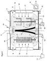
- FIG. 1 shows a schematic cross section through the process chamber 1 of an inventive Coating plant.
- the parts to be coated 2 are on one or more Mounting devices 3 mounted, the means for generating an at least simple 4, If necessary, also includes double 5 rotation of the parts.
- the support devices 3 on an addition to the plant axis 6 rotatable carousel 7 positioned.
- the different process gases, in particular Ar and acetylene, in the process chamber by means of suitable, not shown here control devices be supplied.
- a high vacuum suitable pumping station 9 is flanged to the chamber.
- An ion source 10 is preferably arranged in the region of the system axis, which is connected to the negative output of a DC power supply 11 is connected.
- the positive pole the DC power supply 11 can, depending on the process step via a switch 12 the carousel 7 or to the mounting device 3 and the thus electrically connected Parts 2 (heating process) or to the auxiliary anode 13 (etching process, or if necessary during the coating processes) are created.
- evaporator source 14 On the walls of the process chamber 1 is at least one evaporator source 14, preferably a magnetron or an arc evaporator for applying the adhesion and gradient layer intended.
- evaporator source not shown here 14 this can be used as anodized crucible centrally in the bottom of the process chamber 1 attached.
- the vaporization material is used for producing the transitional or gradient layer by heating through the low-voltage arc 15 in the gas phase converted.
- an additional electrical power supply 16 is provided, with their help to the substrates a periodically varying medium frequency voltage in the range between 1-10,000, preferably between 20 and 250 kHz can be applied.
- the electromagnetic coils 17 for generating a longitudinal, the plasma space penetrating magnetic field are on opposite boundary walls of the process chamber 1 and are separated by at least one, preferably two separate, fed here not shown DC voltage sources in the same direction.
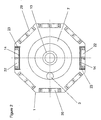
- magnetic systems 20 for forming a plurality of magnetic near fields 21 attached become.
- magnetic systems 20 for forming a plurality of magnetic near fields 21 attached including at least a magnetron magnet system 22, such as shown in FIG. 2, alternately Magnetic systems arranged with NSN or SNS polarity and thus a magnetic tunnel-shaped, looped enclosure of the plasma in the process chamber causes.
- the magnetic systems 20 are formed for near field generation as magnetron magnet systems.
- the individual systems of the coating system are advantageously set in relation to each other by a process control. This makes it possible, in addition to the basic functions of a Vakummbe Anlagenllungsstrom (pump control, safety control loops, etc.), the various plasma-generating systems such as magnetrons with the magnetron supply, ionization chamber 1 and auxiliary anode 13 or carousel 7 and DC power supply 11, and carousel 7 and Medium frequency generator 16, as well as the corresponding adjustment of the gas flows, as well as the control of the optionally different coil currents in a flexible manner to adapt to each other and to optimize for different processes.
- the various plasma-generating systems such as magnetrons with the magnetron supply, ionization chamber 1 and auxiliary anode 13 or carousel 7 and DC power supply 11, and carousel 7 and Medium frequency generator 16, as well as the corresponding adjustment of the gas flows, as well as the control of the optionally different coil currents in a flexible
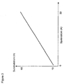
- Figure 3 shows the relationship between substrate current and coil current in use Helmholtz coils to build a magnetic field. It turns out that the substrate current, and thus the plasma intensity directly proportional to the coil current and thus are for magnetic field structure. This clearly shows the positive effect of a superimposed one Magnetic field.
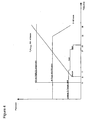
- FIG. 4 shows the course of individual parameters during the application of a Gradient layer shown:
- the substrate bias will be from DC to center frequency with a preferred one Amplitude voltage between 500 and 2500 V and a frequency between 20 and 250 kHz, switched.
- an acetylene ramp is started at 50 sccm and drove over about 30 minutes to 350 sccm.
- the power of the Cr targets used is 7 kW, after another 10 Minutes back to 5 kW, and held there for another 2 minutes constant.
- Apertures are driven in front of the targets and these shut off, bringing the deposition consisting essentially of carbon, small amounts of hydrogen and even lower Quantities of argon atoms built up "pure" DLC layer begins.
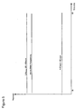
- FIGS. 4 and 5 the course of individual parameters during application is shown by way of example of the pure DLC layer: After switching off the Cr targets used is at constant adjusted medium frequency supply and constant flow of argon the acetylene ramp started during the gradient layer about 10 minutes uniformly increased to a flow between about 200-400 sccm. Subsequently The argon flow is continuously applied to a flow between 5 minutes over a period of 5 minutes about 0 - 100 sccm withdrawn. The next 55 minutes will be added to the process consistent settings completed.
- FIG. 6 shows a scanning electron micrograph of a fracture surface of an inventive device DLC layer system. It can be clearly seen that in the area of the cover layer diamond-like carbon is a fine-grained structure, so that the DLC layer has a polycrystalline character.
- FIG. 7 shows, by way of example, the overall course of individual process parameters during the process Applying an inventive DLC layer system.
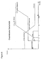
- FIG. 8 shows, by way of example, the overall course of individual process parameters during the application of an inventive DLC sliding layer system with a graphitized sliding layer.
- the pulsed Substratbias set by means of a voltage ramp to a value between 1500 and 2500 V and then deposited an inlet layer under constant conditions.
- FIG. 9 shows an example of the overall course of individual process parameters during the application of an inventive DLC sliding layer system with an inverse gradient layer.
- the acetylene ramp is started, for example, at 350 sccm and driven for about 30 minutes to 50 sccm.
- the process is preferably continued while maintaining the settings until a desired layer thickness of the inlet layer is reached.
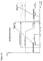
- FIG. 10 shows an example of the course of individual process parameters during the application of a gradient layer as a sliding layer. This can be similar to the transition layer, but also without a metallic adhesive layer, executed.
- FIG. 11 shows, by way of example, the overall course of individual process parameters during the application of an inventive DLC sliding layer system with an H 2 -rich sliding layer.
- a methane ramp is started and, for example, driven from 0 to 100 sccm over about 30 minutes.
- an acetylene ramp is started at 350 sccm and shut down to 120 sccm for about 30 minutes.
- the run-in layer is run as a layer finish with constant parameters.
- the process chamber is pumped down to a pressure of about 10-5 mbar and the process sequence is started.
- a heating process is carried out to bring the substrates to be coated to a higher temperature and to remove volatile substances from the surface.
- an Ar-hydrogen plasma is ignited by means of the low-voltage arc between the ionization chamber and an auxiliary anode.
- Table 1 shows the process parameters of the heating process: Ar flow 75 sccm Substrate Bias Voltage [V] 0 Electricity of low voltage arc 100 A Hydrogen flow 170 sccm Current upper coil Threshold between 20 and 10 A Current lower coil At the same threshold between 20 and 5 A Period between max. and min. coil current 1.5 min heating 20 min
- the Helmholtz coils are used to activate the plasma and become cyclical driven.
- the current of the upper coil is thereby with a period of 1.5 min varies between 20 and 10 A, the current of the lower coil changes in the same clock counterparts between 5 and 20 A.
- the substrates and the annoying adhering to the surfaces heat up Volatile substances are driven into the gas atmosphere, where they are pumped by the vacuum be sucked off.
- an etching process is started by drawing the ions from the low-voltage arc onto the substrates by means of a negative bias voltage of 150V.
- the alignment of the low-voltage arc and the intensity of the plasma are supported by the pair of Helmholtz coils mounted in a horizontal orientation.
- the following table shows the parameters of the etching process.
- the application of the Cr adhesion layer is begun by the Cr magnetron sputtering targets to be activated.
- the Ar gas flow is set at 115 sccm.
- the Cr sputtering targets are driven with a power of 8 kW and become the substrates now rotates past the targets for a time of 6 minutes.
- the self-adjusting pressure range then lies between 10-3 mbar and 10-4 mbar.
- the sputtering process is through the connection of the low-voltage arc and applying a negative DC bias voltage of 75 V supported on the substrate.
- the low voltage arc is turned off and the deposition is active for the remainder of the Cr sputtering time only with the help of the Cr target Plasmas made.
- a plasma is ignited by switching on a sine wave generator.
- Acetylene gas is introduced at an initial pressure of 50 sccm and the flow is increased by 10 sccm every minute.
- the sine plasma generator is set at a frequency of 40 kHz to an amplitude voltage of 2400 V.
- the generator ignites a plasma discharge between the substrate holders and the housing wall.
- the Helmholtz coils attached to the recipient are both activated with a constant current flow of 3 A in the lower coil and 10 A in the upper coil.
- the Cr targets are deactivated.
- the table shows the parameters of the example at a glance: River Argon 50 sccm Flow acetylene 350 sccm Excitation current upper coil 10 A Excitation current lower coil 3 A voltage amplitude 2400 V Excitation frequency f 40 kHz
- the deposition rate is now in the Coating process will range between 0.5 and 4 ⁇ m / h, which also depends on the area to be coated in the process chamber.
- the sine generator and the gas flow are switched off, and the substrates are taken from the process chamber.
- Example 2 provides a procedure similar to Example 1. Unlike example 1, the plasma is generated by a pulse generator.
- the excitation frequency is included 50 kHz with an amplitude voltage of 700V.
- the table shows the parameters of the second example.
- River Argon 50 sccm Flow acetylene 350 sccm Excitation current upper coil 10 A Excitation current lower coil 3 A voltage amplitude 700V Excitation frequency f 40 kHz
- the coating produced has a hardness of 25 GPa, an adhesive strength of HF1 and gives a coefficient of friction of 0.2.
- Properties Example 2 HK about 2400 deposition rate about 1.5 ⁇ m / h liability HF1 resistance > 500k Hydrogen content 13% Coefficient of friction 0.2 Internal tension Approximately 3 GPa
- Example 3 provides a procedure similar to Example 1. In contrast to Example 1, the plasma is excited by a unipolar pulse voltage, the parameters of the experiment are shown in the following table. River Argon 50 sccm Flow acetylene 350 sccm Excitation current upper coil 10 A Excitation current lower coil 3 A voltage amplitude 1150V Excitation frequency f 30 kHz
- the coating produced has the properties described in the following table.
- Example 4 In comparison with Process Example 1, in Example 4, a process without assistance of a longitudinal magnetic field was performed. The current flowing through the two coils was reduced to a value of 0 A.
- the table shows the process parameters. River Argon 50 sccm Flow acetylene 350 sccm Excitation current upper coil 0A Excitation current lower coil 0A voltage amplitude 2400 V Excitation frequency f 40 kHz
- the acetylene ramp can also be delayed by 5-10 minutes Switching on the Cr targets are started. Such a procedure is particularly advantageous if DLC and sliding layer in different process chambers or coating plants be applied. It can also be used instead of the sine wave generator DC voltage source for applying the Suabstratbias be used.
- the Graphitanteil can be switched on by simultaneous or delayed Co-sputtering of carbidic example, WC and / or Graphittargets be increased. If you want the most favorable sliding properties of W or Ta or Nb / C layers It is advantageous to use the Cr targets after the formation of an adhesive or Turn off gradient or downgrade the process and only with the corresponding metal or Metallkarbidtargets to complete.
- the properties of the corresponding DLC layers are Table 8 and ceremoniesNr. 5 6 7 liability HF 1 HF 1 HF 1 resistance ⁇ 100 k ⁇ ⁇ 100 kQ ⁇ 100 k ⁇ Coefficient of friction about 0.10 approx. 0.15 approx. 0.12
- Table 9 shows: protestNr. 8th 9 10 liability HF 1 HF 1 HF 1 resistance ⁇ 1 k ⁇ ⁇ 1 k ⁇ ⁇ 100 k ⁇ Hydrogen content ng ng > 30 atom% Coefficient of friction about 0.08 about 0.07 approx. 0.13
Landscapes
- Chemical & Material Sciences (AREA)
- Engineering & Computer Science (AREA)
- Organic Chemistry (AREA)
- Chemical Kinetics & Catalysis (AREA)
- Materials Engineering (AREA)
- Mechanical Engineering (AREA)
- Metallurgy (AREA)
- Inorganic Chemistry (AREA)
- General Chemical & Material Sciences (AREA)
- Physics & Mathematics (AREA)
- Plasma & Fusion (AREA)
- Analytical Chemistry (AREA)
- Chemical Vapour Deposition (AREA)
- Physical Vapour Deposition (AREA)
- Carbon And Carbon Compounds (AREA)
- Laminated Bodies (AREA)
- Glass Compositions (AREA)
- Lubricants (AREA)
Claims (39)
- Système de couches pour la protection contre l'usure, la protection contre la corrosion et l'amélioration des propriétés de glissement et similaires avec une couche adhésive pour la disposition sur un substrat, une couche de transition pour la disposition sur la couche adhésive et une couche de couverture en carbone similaire au diamant, dans lequel la couche adhésive comprend au moins un élément du groupe contenant les éléments des groupes IV, V et VI et le silicium, la couche de transition contient du carbone et au moins un élément du groupe contenant les éléments des groupes associés IV, V et VI et le silicium, caractérisé en ce que la couche de couverture comprend essentiellement du carbone similaire au diamant, présente une épaisseur de 0,5 µm à 20 µm, et contient exclusivement du carbone ou du carbone et de l'hydrogène, le système de couches présentant une dureté d'au moins 15 GPa, de préférence au moins 20 GPa, et une adhérence d'au moins 3 HF selon le procédé de mesure conforme au document VDI (Association des ingénieurs allemands) 3824, feuillet 4.
- Système de couches selon la revendication 1, caractérisé en ce que la couche de transition est une couche à gradient individuelle ou à plusieurs couches se modifiant continuellement ou par paliers au niveau de la composition, à savoir avec un substrat à l'avant formé d'une part de carbone croissante, et d'une part décroissante d'au moins un élément du groupe contenant les éléments des groupes associés IV, V et VI et le silicium.
- Système de couches selon l'une des revendications précédentes, caractérisé en ce que la couche de couverture présente une épaisseur supérieure à celle de la couche adhésive et de la couche de transition.
- Système de couches selon une des revendications précédentes, caractérisé en ce que la couche de transition et/ou la couche de couverture comprend en plus de l'hydrogène et des impuretés inévitables, les impuretés inévitables contenant des gaz rares, en particulier de l'Argon et du Xénon.
- Système de couches selon la revendication 4, caractérisé en ce que la couche de couverture possède une teneur en hydrogène de 5 à 30 % atomique, de préférence de 10 à 20 % atomique.
- Système de couches selon l'une des revendications précédentes, caractérisé en ce que le au moins un élément du groupe comprenant les éléments des groupes IV, V et VI est du titane et/ou du chrome.
- Système de couches selon l'une des revendications précédentes, caractérisé en ce que la couche adhésive et la couche de transition présentent respectivement une épaisseur de 0,05 µm à 1,5 µm, de préférence de 0,1 µm à 0,8 µm.
- Système de couches selon l'une des revendications précédentes, caractérisé en ce que la couche de couverture présente une épaisseur de 1 µm à 10 µm.
- Système de couches selon l'une des revendications précédentes, caractérisé en ce que la couche de couverture composée de carbone similaire au diamant présente une structure de couches à grain fin avec une valeur de rugosité Rz < 0,8, de préférence Rz < 0,5.
- Procédé de fabrication d'un système de couches, en particulier selon une des revendications 1 à 9, sur un substrat, caractérisé en ce que le procédé comprend :dans lequel au moins pendant les étapes de procédé c), d) et e), une tension de polarisation de substrat unipolaire ou bipolaire est appliquée au substrat, laquelle oscille avec une fréquence moyenne de 1 à 10 000 kHz, de préférence 20 à 250 kHz, et au moins pendant les étapes de procédé d) et e), le plasma est stabilisé par un champ magnétique.a) la pose du substrat dans une chambre à vide et vidage à la pompe jusqu'à obtention d'un vide ayant une pression inférieure à 10-4 mbar, de préférence 10-5 mbar.b) le nettoyage de la surface du substratc) la métallisation sous vide par plasma de la couche adhésive sur le substratd) l'application de la couche de transition sur la couche adhésive par métallisation sous vide par plasma des composants de la couche adhésive et extraction du carbone hors de la phase gazeusee) l'application de la couche de carbone similaire au diamant sur la couche de transition par extraction, soutenue au plasma, du carbone hors de la phase gazeuse,
- Procédé selon la revendication 10, caractérisé en ce que le nettoyage de la surface de substrat comprend une étape de chauffage et/ou une étape de gravure.
- Procédé selon la revendication 11, caractérisé en ce que l'étape de chauffage est réalisée par chauffage par rayonnement, chauffage par induction et/ou par bombardement électronique.
- Procédé selon la revendication 12, caractérisé en ce que le bombardement électronique est provoqué par l'allumage d'un arc électrique basse tension et l'application simultanée d'une tension de polarisation continue, alternative ou alternative superposée, telle que en particulier une tension de polarisation de substrat positive oscillante.
- Procédé selon la revendication 11, caractérisé en ce que l'étape de gravure est réalisée par gravure ionique, un arc électrique basse tension étant allumé avec un gaz rare, de préférence de l'Argon, et/ou de l'hydrogène en tant que gaz de process, et une tension de polarisation de substrat négative continue étant appliquée au substrat.
- Procédé selon la revendication 11, caractérisé en ce que l'étape de gravure est réalisée par gravure ionique avec un gaz rare, de préférence de l'Argon, et/ou de l'hydrogène en tant que gaz de process, une tension de polarisation, alternative ou alternative superposée, telle que en particulier une tension de polarisation de substrat oscillante de préférence de moyenne fréquence, étant appliquée.
- Procédé selon l'une des revendications 10 à 15, caractérisé en ce que la métallisation sous vide de la couche adhésive a lieu par procédé de dépôt chimique en phase vapeur (CVD) par plasma, par procédé physique de dépôt en phase gazeuse, en particulier évaporation d'arc, pulvérisation cathodique, évaporation depuis un creuset au moyen de l'arc basse tension, de préférence au moyen d'un procédé de placage ionique.
- Procédé selon la revendication 16, caractérisé en ce que la métallisation sous vide de la couche adhésive est réalisée avec une décharge d'arc électrique basse tension, et en ce qu'une tension de polarisation de substrat négative est appliquée au substrat.
- Procédé selon la revendication 16, caractérisé en ce que la métallisation sous vide de la couche adhésive est réalisée avec une tension de polarisation de substrat oscillante supplémentaire, en sorte qu'une tension de polarisation alternative ou alternative superposée est appliquée, telle que en particulier une tension de polarisation de substrat oscillante avec une fréquence moyenne de 1 à 20 000 kHz, de préférence de 20 à 250 kHz.
- Procédé selon une des revendications 10 à 18, caractérisé en ce que pour l'allumage d'un plasma, un gaz rare ou un mélange de gaz rare et d'hydrogène, de préférence un mélange d'Argon et d'hydrogène, est introduit dans la chambre à vide.
- Procédé selon une des revendications 10 à 19, caractérisé en ce que la couche de transition est formée par métallisation sous vide simultanée d'au moins un élément du groupe contenant les éléments des groupes IV, V, et VI et le silicium, selon un procédé selon une des revendications 16 à 19 et l'extraction par plasma du carbone hors de la phase gazeuse, un gaz contenant du carbone, de préférence un hydrocarbure à l'état gazeux, en particulier de l'acétylène, étant utilisé comme gaz de réaction supplémentaire.
- Procédé selon la revendication 20, caractérisé en ce que, avec l'épaisseur croissante de la couche de transition, la part d'extraction de carbone est augmentée par paliers ou de manière continue.
- Procédé selon une des revendications 10 à 21, caractérisé en ce que la couche de carbone similaire au diamant formant la couche de couverture est produite par séparation par CVD activée par plasma, du carbone hors de la phase gazeuse, moyennant quoi un gaz carboné, de préférence un hydrocarbure à l'état gazeux, en particulier de l'acétylène, étant utilisé en tant que gaz de réaction.
- Procédé selon une des revendications 20 ou 22, caractérisé en ce que le gaz de réaction comprend pour l'extraction du carbone, en plus du gaz carboné, de l'hydrogène et/ou du gaz rare, de préférence de l'Argon ou/et du Xénon.
- Procédé selon la revendication 23, caractérisé en ce que pendant la séparation de la couche de couverture en carbone similaire au diamant, la part de gaz carboné augmente et/ou la part de gaz rare, en particulier de l'Argon, diminue.
- Procédé selon la revendication 10, caractérisé en ce que la tension de polarisation de substrat est sinusoïdale, ou oscille de telle manière que des temps d'impulsion négatifs longs ou positifs courts ou de grandes amplitudes négatives et de faibles amplitudes positives sont appliqués.
- Procédé selon une des revendications 10 à 25, caractérisé en ce que pendant le nettoyage et/ou l'application de la couche adhésive et/ou de la couche de transition et/ou de la couche de couverture en carbone similaire au diamant, un champ magnétique longitudinal avec tracé de ligne de champ constant est superposé au substrat, le champ magnétique étant modifiable dans le temps et/ou spatialement continuellement ou par paliers.
- Procédé selon une des revendications 10 à 26, caractérisé en ce que l'application de la couche adhésive et/ou de la couche de transition et/ou de la couche de couverture en carbone similaire au diamant a lieu à une pression de 10-4 mbar à 10-2 mbar.
- Dispositif de revêtement d'un ou plusieurs substrats, en particulier pour la réalisation du procédé de revêtement selon une des revendications 10 à 27, avec une chambre à vide (1), avec un système de pompe (9) pour la production d'un vide dans la chambre à vide (1), des supports de substrats (3) pour le logement des substrats à recouvrir, au moins une unité d'alimentation en gaz (8) pour l'addition dosée de gaz de process, au moins un dispositif à évaporation (14) pour la fourniture de matériau de revêtement pour l'évaporation, une installation de production d'arc électrique (10, 143) pour l'allumage d'un arc basse tension à tension continue, un dispositif (16) pour la production d'une tension de polarisation de substrat qui est configurée de telle sorte que la tension de polarisation de substrat peut être exploitée de façon bipolaire, de préférence avec une fréquence située dans une zone de fréquence moyenne, et avec au moins une ou plusieurs installations de production de champ magnétique (17) pour la configuration d'un champ magnétique lointain.
- Dispositif selon la revendication 28, caractérisé en ce que l'installation de production des champs magnétiques (17) est formée par au moins une bobine de Helmholtz.
- Dispositif selon la revendication 29, caractérisé en ce que la bobine de Helmholtz peut être commandée du point de vue de la densité de flux magnétique productible.
- Dispositif selon une des revendications 28 à 30, caractérisé en ce que le dispositif à évaporation (14) comprend des cibles de pulvérisation cathodique, en particulier des cibles de pulvérisation cathodique de magnétron, des sources d'arc, au moyen de creusets chauffés par arc basse tension, d'autres évaporateurs thermiques et similaires.
- Dispositif selon une des revendications 28 à 31, caractérisé en ce que le dispositif à évaporation (14) peut être séparé de l'autre chambre de traitement (1).
- Dispositif selon une des revendications 28 à 32, caractérisé en ce que le dispositif comprend en outre un chauffage de substrat sous la forme d'un chauffage par induction, chauffage à rayonnement ou similaires.
- Dispositif selon une des revendications 28 à 33, caractérisé en ce que l'installation de production d'arc lumineux (10, 13) comprend une source d'ions (10) et une anode (13), ainsi qu'une alimentation en tension continue (11), la source d'ions (10) étant reliée au pôle négatif de l'alimentation en tension continue (11).
- Dispositif selon la revendication 34, caractérisé en ce que le pôle positif de l'alimentation en tension continue (11) peut être relié au choix à l'anode (13) ou aux supports de substrat (3).
- Dispositif selon une des revendications 34 ou 35, caractérisé en ce que la source d'ions (10) comprend un filament, de préférence un filament réfractaire, en particulier en tungstène, en tantale ou similaire, qui est disposé dans une chambre d'ionisation qui peut être séparée de la chambre de traitement (1) par un écran, de préférence un écran réfractaire, en particulier en tungstène, en tantale ou similaire.
- Dispositif selon une des revendications 28 à 36, caractérisé en ce que les supports de substrat (3) sont mobiles, et en effet de préférence rotatifs autour d'au moins un ou plusieurs axes.
- Dispositif selon une des revendications 28 à 37, caractérisé en ce que des aimants permanents (20) sont prévus en plus pour la production d'un champ proche magnétique.
- Dispositif selon la revendication 38, caractérisé en ce que les aimants permanents (20) supplémentaires sont conçus circulaires autour de la chambre à vide (1), de préférence avec une orientation des pôles alternante, et sont configurés en particulier comme des pièges magnétoélectroniques.
Applications Claiming Priority (4)
| Application Number | Priority Date | Filing Date | Title |
|---|---|---|---|
| DE10018143 | 2000-04-12 | ||
| DE10018143A DE10018143C5 (de) | 2000-04-12 | 2000-04-12 | DLC-Schichtsystem sowie Verfahren und Vorrichtung zur Herstellung eines derartigen Schichtsystems |
| PCT/EP2000/013299 WO2001079585A1 (fr) | 2000-04-12 | 2000-12-27 | Systeme de couches dlc et procede pour produire un tel systeme |
| EP00993868.9A EP1272683B2 (fr) | 2000-04-12 | 2000-12-27 | Systeme de couches dlc et procede pour produire un tel systeme |
Related Parent Applications (2)
| Application Number | Title | Priority Date | Filing Date |
|---|---|---|---|
| EP00993868.9A Division-Into EP1272683B2 (fr) | 2000-04-12 | 2000-12-27 | Systeme de couches dlc et procede pour produire un tel systeme |
| EP00993868.9A Division EP1272683B2 (fr) | 2000-04-12 | 2000-12-27 | Systeme de couches dlc et procede pour produire un tel systeme |
Publications (4)
| Publication Number | Publication Date |
|---|---|
| EP1362931A1 EP1362931A1 (fr) | 2003-11-19 |
| EP1362931B1 EP1362931B1 (fr) | 2005-07-20 |
| EP1362931B9 true EP1362931B9 (fr) | 2005-10-05 |
| EP1362931B2 EP1362931B2 (fr) | 2019-08-21 |
Family
ID=7638477
Family Applications (2)
| Application Number | Title | Priority Date | Filing Date |
|---|---|---|---|
| EP00993868.9A Expired - Lifetime EP1272683B2 (fr) | 2000-04-12 | 2000-12-27 | Systeme de couches dlc et procede pour produire un tel systeme |
| EP03014612.0A Expired - Lifetime EP1362931B2 (fr) | 2000-04-12 | 2000-12-27 | Procédé et dispositif pour la fabrication d'un système de couches de DLC |
Family Applications Before (1)
| Application Number | Title | Priority Date | Filing Date |
|---|---|---|---|
| EP00993868.9A Expired - Lifetime EP1272683B2 (fr) | 2000-04-12 | 2000-12-27 | Systeme de couches dlc et procede pour produire un tel systeme |
Country Status (11)
| Country | Link |
|---|---|
| US (5) | US6740393B1 (fr) |
| EP (2) | EP1272683B2 (fr) |
| JP (1) | JP4849759B2 (fr) |
| KR (1) | KR100762346B1 (fr) |
| AT (2) | ATE299956T1 (fr) |
| AU (1) | AU2844001A (fr) |
| BR (1) | BR0017216A (fr) |
| DE (3) | DE10018143C5 (fr) |
| ES (2) | ES2252092T3 (fr) |
| PT (1) | PT1362931E (fr) |
| WO (1) | WO2001079585A1 (fr) |
Cited By (3)
| Publication number | Priority date | Publication date | Assignee | Title |
|---|---|---|---|---|
| DE102013007146A1 (de) * | 2013-04-25 | 2014-10-30 | Oerlikon Trading Ag, Trübbach | DLC Beschichtung mit Einlaufschicht |
| US9534291B2 (en) | 2013-02-21 | 2017-01-03 | Oerlikon Surface Solutions Ag, Pfäffikon | DLC coating with run-in layer |
| US9840779B2 (en) | 2013-02-21 | 2017-12-12 | Oerlikon Surface Solutions Ag, Pfäffikon | Decorative, jet-black coating |
Families Citing this family (199)
| Publication number | Priority date | Publication date | Assignee | Title |
|---|---|---|---|---|
| JP3555844B2 (ja) | 1999-04-09 | 2004-08-18 | 三宅 正二郎 | 摺動部材およびその製造方法 |
| US7250196B1 (en) * | 1999-10-26 | 2007-07-31 | Basic Resources, Inc. | System and method for plasma plating |
| DE10018143C5 (de) * | 2000-04-12 | 2012-09-06 | Oerlikon Trading Ag, Trübbach | DLC-Schichtsystem sowie Verfahren und Vorrichtung zur Herstellung eines derartigen Schichtsystems |
| JP2003231203A (ja) * | 2001-08-21 | 2003-08-19 | Toshiba Corp | 炭素膜被覆部材 |
| EP1486695B1 (fr) * | 2001-09-27 | 2011-04-06 | Kabushiki Kaisha Toyota Chuo Kenkyusho | Element coulissant a coefficient de frottement eleve |
| DE10149588B4 (de) * | 2001-10-08 | 2017-09-07 | Oerlikon Trading Ag, Trübbach | Verfahren zur Diamantbeschichtung von Substraten |
| JP2003206820A (ja) * | 2002-01-17 | 2003-07-25 | Keihin Corp | 電磁式燃料噴射弁 |
| DE10203730B4 (de) * | 2002-01-30 | 2010-09-16 | Fraunhofer-Gesellschaft zur Förderung der angewandten Forschung e.V. | Verfahren zur Abscheidung von metallfreien Kohlenstoffschichten |
| GB0205959D0 (en) * | 2002-03-14 | 2002-04-24 | Teer Coatings Ltd | Apparatus and method for applying diamond-like carbon coatings |
| US20030180450A1 (en) * | 2002-03-22 | 2003-09-25 | Kidd Jerry D. | System and method for preventing breaker failure |
| BR0309661A (pt) * | 2002-04-25 | 2005-02-22 | Unaxis Balzers Ag | Sistema de camadas estruturado |
| DE10223844B4 (de) * | 2002-05-28 | 2013-04-04 | Danfoss A/S | Wasserhydraulische Maschine |
| JP2004138128A (ja) * | 2002-10-16 | 2004-05-13 | Nissan Motor Co Ltd | 自動車エンジン用摺動部材 |
| DE10305159B4 (de) * | 2002-11-02 | 2006-12-07 | Rowapack Gmbh Verpackungsdesign Und Stanztechnik | Stanzverfahren |
| US6969198B2 (en) | 2002-11-06 | 2005-11-29 | Nissan Motor Co., Ltd. | Low-friction sliding mechanism |
| DE10256063A1 (de) * | 2002-11-30 | 2004-06-17 | Mahle Gmbh | Verfahren zum Beschichten von Kolbenringen für Verbrennungsmotoren |
| US7866343B2 (en) | 2002-12-18 | 2011-01-11 | Masco Corporation Of Indiana | Faucet |
| US8220489B2 (en) | 2002-12-18 | 2012-07-17 | Vapor Technologies Inc. | Faucet with wear-resistant valve component |
| DE10259174B4 (de) * | 2002-12-18 | 2006-10-12 | Robert Bosch Gmbh | Verwendung eines tribologisch beanspruchten Bauelements |
| US7866342B2 (en) | 2002-12-18 | 2011-01-11 | Vapor Technologies, Inc. | Valve component for faucet |
| US8555921B2 (en) | 2002-12-18 | 2013-10-15 | Vapor Technologies Inc. | Faucet component with coating |
| SE526481C2 (sv) | 2003-01-13 | 2005-09-20 | Sandvik Intellectual Property | Ythärdat rostfritt stål med förbättrad nötningsbeständighet och låg statisk friktion |
| US20060226003A1 (en) * | 2003-01-22 | 2006-10-12 | John Mize | Apparatus and methods for ionized deposition of a film or thin layer |
| US7416786B2 (en) * | 2003-02-26 | 2008-08-26 | Sumitomo Electric Industries, Ltd. | Amorphous carbon film, process for producing the same and amorphous carbon film-coated material |
| US20040258547A1 (en) * | 2003-04-02 | 2004-12-23 | Kurt Burger | Pump piston and/or elements sealing the pump piston, in particular a sealing ring of elastomeric material, and a device and method for coating an object of elastomeric material |
| JP3891433B2 (ja) | 2003-04-15 | 2007-03-14 | 日産自動車株式会社 | 燃料噴射弁 |
| RU2240376C1 (ru) * | 2003-05-22 | 2004-11-20 | Ооо "Альбатэк" | Способ формирования сверхтвердого аморфного углеродного покрытия в вакууме |
| EP1479946B1 (fr) | 2003-05-23 | 2012-12-19 | Nissan Motor Co., Ltd. | Piston pour un moteur à combustion interne |
| EP1482190B1 (fr) | 2003-05-27 | 2012-12-05 | Nissan Motor Company Limited | Elément de roulement |
| JP2004360649A (ja) | 2003-06-06 | 2004-12-24 | Nissan Motor Co Ltd | エンジン用ピストンピン |
| DE602004004150T2 (de) | 2003-07-25 | 2007-10-11 | Nv Bekaert Sa | Substrat mit zwischenüberzug und hartem kohlenstoffüberzug |
| JP4863152B2 (ja) | 2003-07-31 | 2012-01-25 | 日産自動車株式会社 | 歯車 |
| EP1666573B1 (fr) | 2003-08-06 | 2019-05-15 | Nissan Motor Company Limited | Mecanisme coulissant a faible frottement et procede de reduction de frottement |
| JP2005054617A (ja) | 2003-08-08 | 2005-03-03 | Nissan Motor Co Ltd | 動弁機構 |
| JP4973971B2 (ja) | 2003-08-08 | 2012-07-11 | 日産自動車株式会社 | 摺動部材 |
| JP4117553B2 (ja) | 2003-08-13 | 2008-07-16 | 日産自動車株式会社 | チェーン駆動装置 |
| DE602004008547T2 (de) | 2003-08-13 | 2008-05-21 | Nissan Motor Co., Ltd., Yokohama | Struktur zur Verbindung von einem Kolben mit einer Kurbelwelle |
| JP4539205B2 (ja) | 2003-08-21 | 2010-09-08 | 日産自動車株式会社 | 冷媒圧縮機 |
| US7771821B2 (en) | 2003-08-21 | 2010-08-10 | Nissan Motor Co., Ltd. | Low-friction sliding member and low-friction sliding mechanism using same |
| EP1508611B1 (fr) | 2003-08-22 | 2019-04-17 | Nissan Motor Co., Ltd. | Boîte de vitesse comprenant une composition d`huile de transmission |
| WO2005029538A2 (fr) * | 2003-09-22 | 2005-03-31 | Seok Kyun Song | Generateur de plasma et procede d'alignement destine a des ecrans a cristaux liquides, utilisant ce generateur |
| US20050126497A1 (en) * | 2003-09-30 | 2005-06-16 | Kidd Jerry D. | Platform assembly and method |
| US7824498B2 (en) | 2004-02-24 | 2010-11-02 | Applied Materials, Inc. | Coating for reducing contamination of substrates during processing |
| US20050193852A1 (en) * | 2004-03-05 | 2005-09-08 | Cooper Clark V. | Transmission system with increased power density |
| JP4572688B2 (ja) * | 2004-04-27 | 2010-11-04 | 株式会社豊田中央研究所 | 低摩擦摺動部材 |
| WO2005106065A1 (fr) * | 2004-04-29 | 2005-11-10 | Oc Oerlikon Balzers Ag | Revetement en un materiau dur dlc sur des materiaux a teneur en cuivre pour paliers |
| JP4543373B2 (ja) * | 2004-06-03 | 2010-09-15 | 三菱マテリアル株式会社 | 非鉄材料の高速切削加工ですぐれた耐摩耗性を発揮する表面被覆超硬合金製切削工具の製造方法 |
| EP1771596A1 (fr) * | 2004-07-09 | 2007-04-11 | OC Oerlikon Balzers AG | MATERIAU CONDUCTEUR A BASE DE CUIVRE PRESENTANT UN REVETEMENT EN MATERIAU DUR Me-DLC |
| JP2006116633A (ja) * | 2004-10-20 | 2006-05-11 | Osg Corp | 硬質被膜被覆工具、コーティング被膜、および被膜のコーティング方法 |
| JP2006138404A (ja) * | 2004-11-12 | 2006-06-01 | Kobe Steel Ltd | 水系環境下での耐摩耗性に優れた摺動部材 |
| CH697552B1 (de) * | 2004-11-12 | 2008-11-28 | Oerlikon Trading Ag | Vakuumbehandlungsanlage. |
| EP1698713A1 (fr) * | 2005-03-01 | 2006-09-06 | Ceco Ltd | Material anti-rayures et son procédé de production |
| US9659758B2 (en) * | 2005-03-22 | 2017-05-23 | Honeywell International Inc. | Coils utilized in vapor deposition applications and methods of production |
| US9997338B2 (en) * | 2005-03-24 | 2018-06-12 | Oerlikon Surface Solutions Ag, Pfäffikon | Method for operating a pulsed arc source |
| CN101233598B (zh) * | 2005-05-04 | 2013-05-01 | 奥尔利康贸易股份公司(特吕巴赫) | 用于等离子体处理设备的等离子体增强器 |
| US8033550B2 (en) * | 2005-05-26 | 2011-10-11 | Sulzer Metaplas Gmbh | Piston ring having hard multi-layer coating |
| US20060278520A1 (en) * | 2005-06-13 | 2006-12-14 | Lee Eal H | Use of DC magnetron sputtering systems |
| CN1899992A (zh) * | 2005-07-19 | 2007-01-24 | 鸿富锦精密工业(深圳)有限公司 | 模仁及其制备方法 |
| EP1915472B1 (fr) * | 2005-08-18 | 2018-09-05 | Oerlikon Surface Solutions AG, Pfäffikon | Substrat revêtu d une structure stratifiée comprenant une couche de carbone tétraédrique et une couche extérieure plus molle |
| ATE452218T1 (de) * | 2005-09-10 | 2010-01-15 | Schaeffler Kg | VERSCHLEIßFESTE BESCHICHTUNG UND VERFAHREN ZUR HERSTELLUNG DERSELBEN |
| CN100482379C (zh) * | 2005-10-27 | 2009-04-29 | 鸿富锦精密工业(深圳)有限公司 | 一种压铸模仁及其制备方法 |
| DE102005054132B4 (de) * | 2005-11-14 | 2020-03-26 | Robert Bosch Gmbh | Ventil zum Steuern eines Fluids mit Tribosystem |
| WO2007064332A1 (fr) * | 2005-12-02 | 2007-06-07 | United Technologies Corporation | Revetements de carbone sous forme de diamant exempts de metal |
| EP1960564A1 (fr) * | 2005-12-13 | 2008-08-27 | United Technologies Corporation | Procede pour le depot de carbone amorphe |
| JP2007162099A (ja) * | 2005-12-15 | 2007-06-28 | Toyota Motor Corp | 硬質炭素膜及びその製造方法並びに摺動部材 |
| KR100656955B1 (ko) * | 2005-12-30 | 2006-12-14 | 삼성전자주식회사 | 이온 임플랜터의 이온 발생 장치 |
| JP4735309B2 (ja) * | 2006-02-10 | 2011-07-27 | トヨタ自動車株式会社 | 耐キャビテーションエロージョン用部材及びその製造方法 |
| US9526814B2 (en) * | 2006-02-16 | 2016-12-27 | Boston Scientific Scimed, Inc. | Medical balloons and methods of making the same |
| JP5030439B2 (ja) * | 2006-02-28 | 2012-09-19 | 株式会社リケン | 摺動部材 |
| JP2007246996A (ja) * | 2006-03-16 | 2007-09-27 | Tdk Corp | 保護膜及び該保護膜付き内燃機関用部品 |
| EP1999292B1 (fr) * | 2006-03-28 | 2014-01-22 | Sulzer Metaplas GmbH | Appareil de pulvérisation cathodique |
| EP1999776A1 (fr) * | 2006-03-28 | 2008-12-10 | NV Bekaert SA | Appareil pour revêtement |
| JP4704950B2 (ja) | 2006-04-27 | 2011-06-22 | 株式会社神戸製鋼所 | 非晶質炭素系硬質多層膜及びこの膜を表面に備えた硬質表面部材 |
| US8273222B2 (en) * | 2006-05-16 | 2012-09-25 | Southwest Research Institute | Apparatus and method for RF plasma enhanced magnetron sputter deposition |
| US7939172B2 (en) * | 2006-05-17 | 2011-05-10 | G & H Technologies, Llc | Wear resistant vapor deposited coating, method of coating deposition and applications therefor |
| AT503288B1 (de) * | 2006-07-26 | 2007-09-15 | Bosch Gmbh Robert | Verfahren zum aufbringen eines beschichtungsmaterials sowie beschichtung für eine metallische oberfläche |
| EP1884978B1 (fr) * | 2006-08-03 | 2011-10-19 | Creepservice S.à.r.l. | Procédé pour la revêtement des substrats avec des couches de carbone de type diamant |
| DE102006037774A1 (de) * | 2006-08-11 | 2008-02-14 | Polysius Ag | Walzen- oder Rollenmühle |
| FR2907470B1 (fr) * | 2006-10-20 | 2009-04-17 | Hef Soc Par Actions Simplifiee | Piece en contact glissant, en regime lubrifie, revetue d'une couche mince. |
| DE102006049974A1 (de) * | 2006-10-24 | 2008-04-30 | Oerlikon Leybold Vacuum Gmbh | Turbomaschine |
| DE102006058078A1 (de) * | 2006-12-07 | 2008-06-19 | Systec System- Und Anlagentechnik Gmbh & Co. Kg | Vakuumbeschichtungsanlage zur homogenen PVD-Beschichtung |
| JP2008163430A (ja) * | 2006-12-28 | 2008-07-17 | Jtekt Corp | 高耐食性部材およびその製造方法 |
| DE102007047629A1 (de) * | 2007-04-13 | 2008-10-16 | Stein, Ralf | Verfahren zum Aufbringen einer hochfesten Beschichtung auf Werkstücke und/oder Werkstoffe |
| DE102007019994A1 (de) * | 2007-04-27 | 2008-10-30 | Fraunhofer-Gesellschaft zur Förderung der angewandten Forschung e.V. | Transparente Barrierefolie und Verfahren zum Herstellen derselben |
| BRPI0811241B1 (pt) * | 2007-05-25 | 2019-06-25 | Oerlikon Trading Ag, Trübbach | Instalação e método de tratamento a vácuo |
| KR100897323B1 (ko) * | 2007-05-30 | 2009-05-14 | 한국생산기술연구원 | 플라즈마 화학기상증착과 물리기상증착을 복합한 박막 코팅방법 |
| JP2008310849A (ja) * | 2007-06-12 | 2008-12-25 | Fuji Electric Device Technology Co Ltd | 保護膜形成法及び保護膜を備えた磁気記録媒体 |
| US8105660B2 (en) * | 2007-06-28 | 2012-01-31 | Andrew W Tudhope | Method for producing diamond-like carbon coatings using PECVD and diamondoid precursors on internal surfaces of a hollow component |
| US20090029067A1 (en) * | 2007-06-28 | 2009-01-29 | Sciamanna Steven F | Method for producing amorphous carbon coatings on external surfaces using diamondoid precursors |
| US8277617B2 (en) * | 2007-08-14 | 2012-10-02 | Southwest Research Institute | Conformal magnetron sputter deposition |
| JP2009127059A (ja) * | 2007-11-20 | 2009-06-11 | Tokyo Denki Univ | ダイヤモンドライクカーボン膜の形成方法 |
| US20090194414A1 (en) * | 2008-01-31 | 2009-08-06 | Nolander Ira G | Modified sputtering target and deposition components, methods of production and uses thereof |
| DE102008011921A1 (de) * | 2008-02-29 | 2009-09-10 | Ks Kolbenschmidt Gmbh | Beschichtung von Bauteilen einer Brennkraftmaschine zur Verminderung von Reibung, Verschleiß und Adhäsionsneigung |
| DE102008016864B3 (de) * | 2008-04-02 | 2009-10-22 | Federal-Mogul Burscheid Gmbh | Kolbenring |
| TW200942633A (en) * | 2008-04-14 | 2009-10-16 | Yu-Hsueh Lin | Method for plating film on surface of drill and structure of film-plated drill |
| US8343593B2 (en) * | 2008-05-13 | 2013-01-01 | Sub-One Technology, Inc. | Method of coating inner and outer surfaces of pipes for thermal solar and other applications |
| DE102008028542B4 (de) * | 2008-06-16 | 2012-07-12 | Fraunhofer-Gesellschaft zur Förderung der angewandten Forschung e.V. | Verfahren und Vorrichtung zum Abscheiden einer Schicht auf einem Substrat mittels einer plasmagestützten chemischen Reaktion |
| JP5244495B2 (ja) * | 2008-08-06 | 2013-07-24 | 三菱重工業株式会社 | 回転機械用の部品 |
| TWI399451B (zh) * | 2008-09-05 | 2013-06-21 | Yu Hsueh Lin | 傳動機構之表面鍍膜方法 |
| DE102008042896A1 (de) * | 2008-10-16 | 2010-04-22 | Federal-Mogul Burscheid Gmbh | Verfahren zur Beschichtung eines Gleitelements und Gleitelement, insbesondere Kolbenring oder Zylinderlaufbuchse eines Verbrennungsmotors |
| US8332314B2 (en) | 2008-11-05 | 2012-12-11 | Kent Griffin | Text authorization for mobile payments |
| US7939367B1 (en) * | 2008-12-18 | 2011-05-10 | Crystallume Corporation | Method for growing an adherent diamond layer atop an interlayer bonded to a compound semiconductor substrate |
| JP4755262B2 (ja) * | 2009-01-28 | 2011-08-24 | 株式会社神戸製鋼所 | ダイヤモンドライクカーボン膜の製造方法 |
| JP5222764B2 (ja) * | 2009-03-24 | 2013-06-26 | 株式会社神戸製鋼所 | 積層皮膜および積層皮膜被覆部材 |
| JP5741891B2 (ja) * | 2009-06-19 | 2015-07-01 | 株式会社ジェイテクト | Dlc膜形成方法 |
| RU2553803C2 (ru) * | 2009-08-07 | 2015-06-20 | Эрликон Трейдинг Аг, Трюббах | Трибология в сочетании с коррозионной стойкостью: новое семейство pvd- и pacvd-покрытий |
| DE102009028504C5 (de) * | 2009-08-13 | 2014-10-30 | Federal-Mogul Burscheid Gmbh | Kolbenring mit einer Beschichtung |
| US9208999B2 (en) * | 2009-11-20 | 2015-12-08 | Oerlikon Surface Solultions Ag, Trubbach | Coil section assembly for simulating circular coils for vacuum devices |
| US8715789B2 (en) | 2009-12-18 | 2014-05-06 | Sub-One Technology, Inc. | Chemical vapor deposition for an interior of a hollow article with high aspect ratio |
| JP5628893B2 (ja) * | 2010-03-03 | 2014-11-19 | 太陽化学工業株式会社 | 非晶質炭素膜からなる層への固定化方法及び積層体 |
| US8747631B2 (en) * | 2010-03-15 | 2014-06-10 | Southwest Research Institute | Apparatus and method utilizing a double glow discharge plasma for sputter cleaning |
| US9169551B2 (en) * | 2010-04-15 | 2015-10-27 | DePuy Synthes Products, Inc. | Coating for a CoCrMo substrate |
| KR101779776B1 (ko) * | 2010-04-15 | 2017-09-19 | 신세스 게엠바하 | 코발트크롬몰리브덴 기재를 위한 코팅 |
| EP2385259A1 (fr) * | 2010-05-06 | 2011-11-09 | Protec Surface Technologies S.r.L. | Cylindre actionné par un fluide pour un véhicule de manutention |
| JP5649333B2 (ja) * | 2010-06-01 | 2015-01-07 | 株式会社神戸製鋼所 | イオンボンバードメント装置及びこの装置を用いた基材表面のクリーニング方法 |
| PL2585622T3 (pl) * | 2010-06-22 | 2018-07-31 | Oerlikon Surface Solutions Ag, Pfäffikon | Źródło odparowania łukowego o określonym polu elektrycznym |
| DE112011102310B4 (de) * | 2010-07-09 | 2017-01-26 | Daido Metal Company Ltd. | Gleitlager |
| KR101436109B1 (ko) * | 2010-07-09 | 2014-09-01 | 다이도 메탈 고교 가부시키가이샤 | 슬라이딩 부재 |
| JP5665409B2 (ja) * | 2010-08-06 | 2015-02-04 | 株式会社ジェイテクト | 被膜の成膜方法 |
| DE102010062114B4 (de) * | 2010-11-29 | 2014-12-11 | Federal-Mogul Burscheid Gmbh | Gleitelement, insbesondere Kolbenring, mit einer Beschichtung |
| DE102011009347B4 (de) | 2010-11-29 | 2016-05-12 | Fraunhofer-Gesellschaft zur Förderung der angewandten Forschung e.V. | Verfahren zur Herstellung eines kohlenstoffhaltigen Schichtsystems sowie Vorrichtung zur Durchführung des Verfahrens |
| DE102010052971A1 (de) | 2010-11-30 | 2012-05-31 | Amg Coating Technologies Gmbh | Werkstück mit Si-DLC Beschichtung und Verfahren zur Herstellung von Beschichtungen |
| CN102108484B (zh) * | 2011-01-18 | 2012-07-04 | 厦门建霖工业有限公司 | 一种双层抗菌镀层的制备方法 |
| CN102108485B (zh) * | 2011-01-28 | 2012-03-28 | 厦门建霖工业有限公司 | 塑胶表面抗菌镀层的制备方法 |
| BRPI1100176A2 (pt) * | 2011-02-10 | 2013-04-24 | Mahle Metal Leve Sa | componente de motor |
| EP2673497B1 (fr) * | 2011-02-11 | 2019-01-23 | Sphenic Technologies Inc. | Système, circuit et procédé permettant de réguler la combustion |
| EP2681346B1 (fr) * | 2011-03-02 | 2017-09-06 | Oerlikon Surface Solutions AG, Pfäffikon | Composant coulissant revêtu d'une couche de carbone comprenant du métal pour l'amélioration de l'usure et du comportement de frottement par des applications tribologiques dans des conditions lubrifiées |
| JP5904537B2 (ja) * | 2011-04-20 | 2016-04-13 | Ntn株式会社 | 非晶質炭素膜の成膜方法 |
| US9909365B2 (en) | 2011-04-29 | 2018-03-06 | Baker Hughes Incorporated | Downhole tools having mechanical joints with enhanced surfaces |
| FR2975404B1 (fr) * | 2011-05-19 | 2014-01-24 | Hydromecanique & Frottement | Piece avec revetement dlc et procede d'application du revetement dlc |
| DE102011077556A1 (de) | 2011-06-15 | 2012-12-20 | Schaeffler Technologies AG & Co. KG | Gleitlager |
| US9340854B2 (en) * | 2011-07-13 | 2016-05-17 | Baker Hughes Incorporated | Downhole motor with diamond-like carbon coating on stator and/or rotor and method of making said downhole motor |
| JP2011225999A (ja) * | 2011-07-21 | 2011-11-10 | Yamaguchi Prefectural Industrial Technology Institute | プラズマ処理装置及び成膜方法 |
| CN103814150B (zh) * | 2011-09-22 | 2015-11-25 | Ntn株式会社 | 硬质膜、硬质膜形成体及滚动轴承 |
| DE102011116576A1 (de) * | 2011-10-21 | 2013-04-25 | Oerlikon Trading Ag, Trübbach | Bohrer mit Beschichtung |
| JP5689051B2 (ja) * | 2011-11-25 | 2015-03-25 | 株式会社神戸製鋼所 | イオンボンバードメント装置 |
| AT511605B1 (de) * | 2011-12-12 | 2013-01-15 | High Tech Coatings Gmbh | Kohlenstoffbasierende beschichtung |
| KR101382997B1 (ko) * | 2012-02-08 | 2014-04-08 | 현대자동차주식회사 | 코팅층 표면 처리 방법 |
| EP2628817B1 (fr) | 2012-02-15 | 2016-11-02 | IHI Hauzer Techno Coating B.V. | Article revêtu d'acier martensitique et procédé de formation d'un article revêtu d'acier |
| ES2543579T3 (es) | 2012-02-15 | 2015-08-20 | Ihi Hauzer Techno Coating B.V. | Componentes de cojinete y cojinetes aislados frente a corriente |
| DE102012007763A1 (de) | 2012-04-20 | 2013-10-24 | Ulrich Schmidt | Modularer Rahmen für Steckdosen und Schalter |
| EP2924142B1 (fr) | 2012-05-15 | 2016-11-16 | ZhongAo HuiCheng Technology Co. Ltd. | Film nano-multicouche |
| RU2494172C1 (ru) * | 2012-08-07 | 2013-09-27 | Федеральное государственное бюджетное образовательное учреждение высшего профессионального образования "Казанский национальный исследовательский технологический университет" (ФГБОУ ВПО "КНИТУ") | Способ получения износостойкого покрытия |
| DE102012214284B4 (de) * | 2012-08-10 | 2014-03-13 | Federal-Mogul Burscheid Gmbh | Gleitelement, insbesondere Kolbenring, mit einer widerstandsfähigen Beschichtung |
| US9793098B2 (en) | 2012-09-14 | 2017-10-17 | Vapor Technologies, Inc. | Low pressure arc plasma immersion coating vapor deposition and ion treatment |
| US9412569B2 (en) | 2012-09-14 | 2016-08-09 | Vapor Technologies, Inc. | Remote arc discharge plasma assisted processes |
| US10056237B2 (en) | 2012-09-14 | 2018-08-21 | Vapor Technologies, Inc. | Low pressure arc plasma immersion coating vapor deposition and ion treatment |
| KR101439131B1 (ko) * | 2012-09-21 | 2014-09-11 | 현대자동차주식회사 | 흡배기 밸브용 코팅재 및 이의 제조방법 |
| TWI565353B (zh) * | 2012-10-19 | 2017-01-01 | 逢甲大學 | 可撓性電熱發熱體及其製作方法 |
| JP5564099B2 (ja) * | 2012-12-28 | 2014-07-30 | 株式会社リケン | シリンダとピストンリングの組合せ |
| JP6076112B2 (ja) * | 2013-02-07 | 2017-02-08 | 株式会社神戸製鋼所 | イオンボンバードメント装置及びこの装置を用いた基材の表面のクリーニング方法 |
| US9308090B2 (en) | 2013-03-11 | 2016-04-12 | DePuy Synthes Products, Inc. | Coating for a titanium alloy substrate |
| US20160281216A1 (en) * | 2013-03-19 | 2016-09-29 | Taiyo Yuden Chemical Technology Co., Ltd. | Structure having stain-proofing amorphous carbon film and method of forming stain-proofing amorphous carbon film |
| JP5780689B2 (ja) * | 2013-03-22 | 2015-09-16 | 日鍛バルブ株式会社 | Dlc被覆膜 |
| JP6103040B2 (ja) * | 2013-03-29 | 2017-03-29 | 日立金属株式会社 | 被覆工具の製造方法 |
| JP2014237890A (ja) * | 2013-05-10 | 2014-12-18 | 国立大学法人電気通信大学 | ダイヤモンドライクカーボン膜の成膜装置および形成方法 |
| US20150004362A1 (en) * | 2013-07-01 | 2015-01-01 | General Electric Company | Multilayered coatings with diamond-like carbon |
| DE102013213454B3 (de) * | 2013-07-09 | 2015-01-15 | Friedrich-Alexander-Universität Erlangen - Nürnberg | Werkzeug zum Einsatz beim Aluminiumguss |
| KR102240656B1 (ko) * | 2013-07-19 | 2021-04-16 | 외를리콘 서피스 솔루션즈 아게, 페피콘 | 성형 공구용 코팅 |
| JP6533374B2 (ja) * | 2013-11-06 | 2019-06-19 | Dowaサーモテック株式会社 | Dlc皮膜の成膜方法 |
| DE102013225608A1 (de) * | 2013-12-11 | 2015-06-11 | Apo Gmbh Massenkleinteilbeschichtung | Vorrichtung und Verfahren zur Oberflächenbehandlung von Kleinteilen mittels Plasma |
| WO2015161469A1 (fr) * | 2014-04-23 | 2015-10-29 | 中奥汇成科技股份有限公司 | Cupule articulaire artificielle, dispositif de pulvérisation de film de revêtement à commande magnétique dispositif et procédé de préparation associé |
| FR3022560B1 (fr) * | 2014-06-18 | 2022-02-25 | Hydromecanique & Frottement | Procede de revetement en carbone dlc du nez des cames d'un arbre a came, arbre a cames ainsi obtenu et installation pour la mise en oeuvre de ce procede |
| JP6044602B2 (ja) | 2014-07-11 | 2016-12-14 | トヨタ自動車株式会社 | 成膜装置 |
| WO2016017375A1 (fr) * | 2014-08-01 | 2016-02-04 | 日立金属株式会社 | Procédé de production d'un outil revêtu |
| US10612123B2 (en) * | 2015-02-04 | 2020-04-07 | The University Of Akron | Duplex surface treatment for titanium alloys |
| CN107532723B (zh) | 2015-04-16 | 2019-11-22 | 伊格尔工业股份有限公司 | 滑动部件 |
| JP6612864B2 (ja) * | 2015-05-28 | 2019-11-27 | 京セラ株式会社 | 切削工具 |
| JP6014941B2 (ja) * | 2015-07-31 | 2016-10-26 | 地方独立行政法人山口県産業技術センター | プラズマ処理装置及び成膜方法 |
| EP3374541B1 (fr) * | 2015-11-12 | 2023-11-29 | National Oilwell DHT, L.P. | Trépan de forage de fond avec un élément de coupe revêtu d'un revêtement contenant du nanodiamant polycristallin |
| CN105734527B (zh) * | 2016-03-08 | 2019-01-18 | 仪征亚新科双环活塞环有限公司 | 一种用于活塞环表面的类金刚石镀层、活塞环及制备工艺 |
| KR101828508B1 (ko) * | 2016-07-13 | 2018-03-29 | 제이와이테크놀로지(주) | Dlc 박막 제조 장치 |
| JP6380483B2 (ja) | 2016-08-10 | 2018-08-29 | トヨタ自動車株式会社 | 成膜装置 |
| DE102016116123B4 (de) * | 2016-08-30 | 2018-07-19 | Federal-Mogul Valvetrain Gmbh | Verschleißarmes Kegelstück |
| US10377508B2 (en) | 2016-11-29 | 2019-08-13 | The Boeing Company | Enhanced tooling for interference-fit fasteners |
| WO2019059054A1 (fr) * | 2017-09-25 | 2019-03-28 | 住友電気工業株式会社 | Procédé pour la fabrication d'un revêtement à base de carbone dur et élément pourvu d'un revêtement |
| US11183373B2 (en) | 2017-10-11 | 2021-11-23 | Honeywell International Inc. | Multi-patterned sputter traps and methods of making |
| KR102055046B1 (ko) * | 2017-12-29 | 2019-12-12 | 트인로드 주식회사 | Dlc 및 다이아몬드 박막이 이중 코팅된 펀칭공구 및 그 제조방법 |
| CN108374154B (zh) * | 2018-02-26 | 2023-06-13 | 温州职业技术学院 | 带有复合磁场的类金刚石涂层制备装置及其应用 |
| US10702862B2 (en) * | 2018-04-13 | 2020-07-07 | U.S. Department Of Energy | Superlubricious carbon films derived from natural gas |
| FR3082527B1 (fr) * | 2018-06-18 | 2020-09-18 | Hydromecanique & Frottement | Piece revetue par un revetement de carbone amorphe non-hydrogene sur une sous-couche comportant du chrome, du carbone et du silicium |
| FR3082526B1 (fr) * | 2018-06-18 | 2020-09-18 | Hydromecanique & Frottement | Piece revetue par un revetement de carbone amorphe hydrogene sur une sous-couche comportant du chrome, du carbone et du silicium |
| DE102018125464B4 (de) * | 2018-10-15 | 2022-09-29 | PiKa GbR (Vertretungsberechtigter Gesellschafter: Markus Pittroff, 91278 Pottenstein) | Sägekette zur Holz- und Kunststoffbearbeitung und Verfahren zur Herstellung eines Sägegliedes |
| EP3650583A1 (fr) | 2018-11-08 | 2020-05-13 | Nanofilm Technologies International Pte Ltd | Revêtements a base de carbone amorphe ta-c à dureté améliorée |
| CN110066982A (zh) * | 2019-04-17 | 2019-07-30 | 厦门阿匹斯智能制造系统有限公司 | 一种pvd镀膜产线磁控溅射的磁场分布方法 |
| DE102019116000A1 (de) * | 2019-06-12 | 2020-12-17 | Schaeffler Technologies AG & Co. KG | Schichtsystem zum Beschichten einer Bipolarplatte, sowie Bipolarplatte und Brennstoffzelle |
| CN114207178B (zh) * | 2019-07-31 | 2024-06-04 | 欧瑞康表面处理解决方案股份公司普费菲孔 | 涂覆于基材上的梯级无氢碳基硬材料层 |
| US11664226B2 (en) | 2020-06-29 | 2023-05-30 | Applied Materials, Inc. | Methods for producing high-density carbon films for hardmasks and other patterning applications |
| US11664214B2 (en) | 2020-06-29 | 2023-05-30 | Applied Materials, Inc. | Methods for producing high-density, nitrogen-doped carbon films for hardmasks and other patterning applications |
| CN111676452A (zh) * | 2020-06-29 | 2020-09-18 | 哈尔滨奥瑞德光电技术有限公司 | 一种高效镀超硬膜的方法 |
| CN111748789B (zh) * | 2020-07-10 | 2022-06-24 | 哈尔滨工业大学 | 一种石墨阴极弧增强辉光放电沉积纯dlc的装置及其方法 |
| EP3964356A1 (fr) * | 2020-09-03 | 2022-03-09 | Boegli-Gravures SA | Procédé et système de fabrication d'un dispositif de gaufrage à l'aide d'un masque de gravure |
| WO2022171697A1 (fr) * | 2021-02-09 | 2022-08-18 | Oerlikon Surface Solutions Ag, Pfäffikon | Contrôle de position et commande de position de faisceau d'arc dans des systèmes de revêtement picvd |
| RU2763357C1 (ru) * | 2021-04-13 | 2021-12-28 | Александр Васильевич Вахрушев | Способ получения высококачественных пленок методом механической вибрации подложки |
| US20240287668A1 (en) * | 2023-02-16 | 2024-08-29 | Samsung Electronics Co., Ltd. | Dlc film deposition apparatus, semiconductor manufacturing system including the dlc film deposition apparatus, and semiconducor manufacturing method using the dlc film deposition apparatus |
| CN116770248A (zh) * | 2023-07-03 | 2023-09-19 | 兰州空间技术物理研究所 | 一种梯度复合碳基薄膜的制备方法 |
| US20250075335A1 (en) * | 2023-08-30 | 2025-03-06 | Ii-Vi Delaware, Inc. | Method and System for Co-Deposited Diamond-Like Carbon Coatings |
| CN117660880A (zh) * | 2023-12-07 | 2024-03-08 | 深圳市金洲精工科技股份有限公司 | 一种用于刀具表面的复合碳层、其制备方法及刀具 |
| DE102024124488A1 (de) * | 2024-08-28 | 2026-03-05 | Schaeffler Technologies AG & Co. KG | Radlageeinheit zur Lagerung eines Fahrzeugrades |
Family Cites Families (182)
| Publication number | Priority date | Publication date | Assignee | Title |
|---|---|---|---|---|
| US50689A (en) * | 1865-10-31 | Improvement in gaging and ullaging casks | ||
| US91154A (en) * | 1869-06-08 | Improvement in attaching- handles to picks | ||
| US50681A (en) * | 1865-10-31 | Improvement in photographic lenses | ||
| US3287630A (en) * | 1964-03-02 | 1966-11-22 | Varian Associates | Apparatus for improving the uniformity of magnetic fields |
| US3458426A (en) * | 1966-05-25 | 1969-07-29 | Fabri Tek Inc | Symmetrical sputtering apparatus with plasma confinement |
| DD133688A1 (de) † | 1977-08-04 | 1979-01-17 | Klaus Bewilogua | Verfahren zur herstellung diamanthaltiger schichten hoher haftfestigkeit |
| US4276570A (en) * | 1979-05-08 | 1981-06-30 | Nancy Burson | Method and apparatus for producing an image of a person's face at a different age |
| DE3260505D1 (en) * | 1981-01-23 | 1984-09-13 | Takeda Chemical Industries Ltd | Alicyclic compounds, their production and use |
| DE3246361A1 (de) * | 1982-02-27 | 1983-09-08 | Philips Patentverwaltung Gmbh, 2000 Hamburg | Kohlenstoff enthaltende gleitschicht |
| US4486286A (en) * | 1982-09-28 | 1984-12-04 | Nerken Research Corp. | Method of depositing a carbon film on a substrate and products obtained thereby |
| US4602280A (en) * | 1983-12-05 | 1986-07-22 | Maloomian Laurence G | Weight and/or measurement reduction preview system |
| US4698256A (en) * | 1984-04-02 | 1987-10-06 | American Cyanamid Company | Articles coated with adherent diamondlike carbon films |
| US4877677A (en) * | 1985-02-19 | 1989-10-31 | Matsushita Electric Industrial Co., Ltd. | Wear-protected device |
| FR2583250B1 (fr) * | 1985-06-07 | 1989-06-30 | France Etat | Procede et dispositif d'excitation d'un plasma par micro-ondes a la resonance cyclotronique electronique |
| CH664768A5 (de) * | 1985-06-20 | 1988-03-31 | Balzers Hochvakuum | Verfahren zur beschichtung von substraten in einer vakuumkammer. |
| DD243514B1 (de) * | 1985-12-17 | 1989-04-26 | Karl Marx Stadt Tech Hochschul | Hartstoffschichten fuer mechanisch und korrosiv beanspruchte teile |
| JPS62188776A (ja) * | 1986-01-14 | 1987-08-18 | Sumitomo Electric Ind Ltd | 対向タ−ゲツト式スパツタ装置 |
| FR2596775B1 (fr) | 1986-04-07 | 1992-11-13 | Univ Limoges | Revetement dur multicouches elabore par depot ionique de nitrure de titane, carbonitrure de titane et i-carbone |
| JPS63195266A (ja) * | 1987-02-10 | 1988-08-12 | Semiconductor Energy Lab Co Ltd | 炭素膜がコーティングされた時計 |
| KR900008505B1 (ko) * | 1987-02-24 | 1990-11-24 | 세미콘덕터 에너지 라보라터리 캄파니 리미티드 | 탄소 석출을 위한 마이크로파 강화 cvd 방법 |
| DE3706340A1 (de) * | 1987-02-27 | 1988-09-08 | Winter & Sohn Ernst | Verfahren zum auftragen einer verschleissschutzschicht und danach hergestelltes erzeugnis |
| WO1990002216A1 (fr) † | 1988-08-25 | 1990-03-08 | Vac-Tec Systems, Inc. | Appareil et procede de revetement double par deposition en phase gazeuse par procede physique |
| DE3708716C2 (de) * | 1987-03-18 | 1993-11-04 | Hans Prof Dr Rer Nat Oechsner | Hochfrequenz-ionenquelle |
| EP0286306B1 (fr) * | 1987-04-03 | 1993-10-06 | Fujitsu Limited | Méthode et appareil de déposition en phase gazeuse de diamant |
| US4926791A (en) * | 1987-04-27 | 1990-05-22 | Semiconductor Energy Laboratory Co., Ltd. | Microwave plasma apparatus employing helmholtz coils and ioffe bars |
| US5113493A (en) * | 1987-05-11 | 1992-05-12 | Liberty Life Insurance Co. | Full speed animation system for low-speed computers and method |
| JPS63286334A (ja) * | 1987-05-19 | 1988-11-24 | Idemitsu Petrochem Co Ltd | 積層体およびその製造法 |
| KR920002864B1 (ko) * | 1987-07-20 | 1992-04-06 | 가부시기가이샤 히다찌세이사꾸쇼 | 플라즈마 처리방법 및 그 장치 |
| ES2022946T5 (es) † | 1987-08-26 | 1996-04-16 | Balzers Hochvakuum | Procedimiento para la aportacion de capas sobre sustratos. |
| NL8800345A (nl) * | 1988-02-12 | 1989-09-01 | Philips Nv | Knipeenheid voor een scheerapparaat en scheerapparaat voorzien van deze knipeenheid. |
| JP2610469B2 (ja) * | 1988-02-26 | 1997-05-14 | 株式会社 半導体エネルギー研究所 | 炭素または炭素を主成分とする被膜を形成する方法 |
| US5411797A (en) * | 1988-04-18 | 1995-05-02 | Board Of Regents, The University Of Texas System | Nanophase diamond films |
| US4952273A (en) * | 1988-09-21 | 1990-08-28 | Microscience, Inc. | Plasma generation in electron cyclotron resonance |
| US4918031A (en) * | 1988-12-28 | 1990-04-17 | American Telephone And Telegraph Company,At&T Bell Laboratories | Processes depending on plasma generation using a helical resonator |
| US4919974A (en) * | 1989-01-12 | 1990-04-24 | Ford Motor Company | Making diamond composite coated cutting tools |
| US4992153A (en) † | 1989-04-26 | 1991-02-12 | Balzers Aktiengesellschaft | Sputter-CVD process for at least partially coating a workpiece |
| US5266409A (en) * | 1989-04-28 | 1993-11-30 | Digital Equipment Corporation | Hydrogenated carbon compositions |
| CZ278295B6 (en) † | 1989-08-14 | 1993-11-17 | Fyzikalni Ustav Avcr | Process of sputtering layers and apparatus for making the same |
| EP0413853B1 (fr) † | 1989-08-21 | 1996-01-31 | Balzers Aktiengesellschaft | Pièce pourvue d'une couche cristalline mixte, procédé et dispositif pour sa production |
| GB9006073D0 (en) † | 1990-03-17 | 1990-05-16 | D G Teer Coating Services Limi | Magnetron sputter ion plating |
| EP0721998B1 (fr) * | 1990-08-03 | 1999-01-13 | Fujitsu Limited | Procédé dépÔt chimique en phase vapeur de diamant |
| DE4029270C1 (fr) * | 1990-09-14 | 1992-04-09 | Balzers Ag, Balzers, Li | |
| KR930011413B1 (ko) * | 1990-09-25 | 1993-12-06 | 가부시키가이샤 한도오따이 에네루기 겐큐쇼 | 펄스형 전자파를 사용한 플라즈마 cvd 법 |
| DE4035131C2 (de) * | 1990-11-05 | 1995-09-21 | Balzers Hochvakuum | Verfahren und Vorrichtung zum gleichmäßigen Erwärmen von Heizgut, insbes. von zu beschichtenden Substraten, in einer Vakuumkammer |
| DE4126852A1 (de) * | 1991-08-14 | 1993-02-18 | Krupp Widia Gmbh | Werkzeug mit verschleissfester diamantschneide, verfahren zu dessen herstellung sowie dessen verwendung |
| US6692359B1 (en) * | 1991-02-15 | 2004-02-17 | America Online, Inc. | Method of interfacing on a computer network by visual representations of users, method of interacting and computer network |
| JPH07109034B2 (ja) * | 1991-04-08 | 1995-11-22 | ワイケイケイ株式会社 | 硬質多層膜形成体およびその製造方法 |
| US5147687A (en) * | 1991-05-22 | 1992-09-15 | Diamonex, Inc. | Hot filament CVD of thick, adherent and coherent polycrystalline diamond films |
| DE69232403T2 (de) * | 1991-08-06 | 2002-08-22 | Canon K.K., Tokio/Tokyo | Dreidimensionales Modellverarbeitungsverfahren und -gerät |
| US5541003A (en) * | 1991-10-31 | 1996-07-30 | Tdk Corporation | Articles having diamond-like protective thin film |
| EP0542628B1 (fr) * | 1991-11-12 | 2001-10-10 | Fujitsu Limited | Système de synthèse de parole |
| US5989511A (en) * | 1991-11-25 | 1999-11-23 | The University Of Chicago | Smooth diamond films as low friction, long wear surfaces |
| US5555426A (en) * | 1992-01-08 | 1996-09-10 | International Business Machines Corporation | Method and apparatus for disseminating messages to unspecified users in a data processing system |
| US5416899A (en) * | 1992-01-13 | 1995-05-16 | Massachusetts Institute Of Technology | Memory based method and apparatus for computer graphics |
| US5680481A (en) * | 1992-05-26 | 1997-10-21 | Ricoh Corporation | Facial feature extraction method and apparatus for a neural network acoustic and visual speech recognition system |
| US5537662A (en) * | 1992-05-29 | 1996-07-16 | Casio Computer Co., Ltd. | Electronic montage composing apparatus |
| US5439492A (en) * | 1992-06-11 | 1995-08-08 | General Electric Company | Fine grain diamond workpieces |
| US5306408A (en) † | 1992-06-29 | 1994-04-26 | Ism Technologies, Inc. | Method and apparatus for direct ARC plasma deposition of ceramic coatings |
| JP3336682B2 (ja) * | 1992-07-02 | 2002-10-21 | 住友電気工業株式会社 | 硬質炭素膜 |
| JPH06111287A (ja) * | 1992-09-30 | 1994-04-22 | Matsushita Electric Ind Co Ltd | 磁気記録媒体 |
| US5420801A (en) * | 1992-11-13 | 1995-05-30 | International Business Machines Corporation | System and method for synchronization of multimedia streams |
| US5640590A (en) * | 1992-11-18 | 1997-06-17 | Canon Information Systems, Inc. | Method and apparatus for scripting a text-to-speech-based multimedia presentation |
| EP0598598B1 (fr) * | 1992-11-18 | 2000-02-02 | Canon Information Systems, Inc. | Processeur de conversion texte-parole et utilisation d'un analyseur dans un tel processeur |
| US5637373A (en) * | 1992-11-19 | 1997-06-10 | Semiconductor Energy Laboratory Co., Ltd. | Magnetic recording medium |
| US5387178A (en) * | 1992-11-23 | 1995-02-07 | Moses; Gary L. | Multi-stimuli chair |
| BE1006711A3 (nl) * | 1992-12-02 | 1994-11-22 | Vito | Werkwijze voor het aanbrengen van een diamantachtige koolstoflaag op staal, ijzer of legeringen daarvan. |
| US5638502A (en) * | 1992-12-25 | 1997-06-10 | Casio Computer Co., Ltd. | Device for creating a new object image relating to plural object images |
| US5249554A (en) * | 1993-01-08 | 1993-10-05 | Ford Motor Company | Powertrain component with adherent film having a graded composition |
| US5237967A (en) * | 1993-01-08 | 1993-08-24 | Ford Motor Company | Powertrain component with amorphous hydrogenated carbon film |
| US5431963A (en) * | 1993-02-01 | 1995-07-11 | General Electric Company | Method for adhering diamondlike carbon to a substrate |
| US5645900A (en) * | 1993-04-22 | 1997-07-08 | The United States Of America As Represented By The Administrator Of The National Aeronautics And Space Administration | Diamond composite films for protective coatings on metals and method of formation |
| SE9301596L (sv) * | 1993-05-10 | 1994-05-24 | Televerket | Anordning för att öka talförståelsen vid översätttning av tal från ett första språk till ett andra språk |
| US5860064A (en) * | 1993-05-13 | 1999-01-12 | Apple Computer, Inc. | Method and apparatus for automatic generation of vocal emotion in a synthetic text-to-speech system |
| US5387288A (en) * | 1993-05-14 | 1995-02-07 | Modular Process Technology Corp. | Apparatus for depositing diamond and refractory materials comprising rotating antenna |
| US5626963A (en) * | 1993-07-07 | 1997-05-06 | Sanyo Electric Co., Ltd. | Hard-carbon-film-coated substrate and apparatus for forming the same |
| DE4421144C2 (de) * | 1993-07-21 | 2003-02-13 | Unaxis Balzers Ag | Beschichtetes Werkzeug mit erhöhter Standzeit |
| AU7381594A (en) † | 1993-07-29 | 1995-02-28 | Institute Of Physics Academy Of Sciences Of The Czech Republic | Method and device for magnetron sputtering |
| BE1008229A3 (nl) * | 1993-10-29 | 1996-02-20 | Vito | Werkwijze voor het aanbrengen van een tegen slijtage beschermende laag op een substraat. |
| US5347306A (en) * | 1993-12-17 | 1994-09-13 | Mitsubishi Electric Research Laboratories, Inc. | Animated electronic meeting place |
| DE4343354C2 (de) * | 1993-12-18 | 2002-11-14 | Bosch Gmbh Robert | Verfahren zur Herstellung einer Hartstoffschicht |
| JPH07175710A (ja) * | 1993-12-20 | 1995-07-14 | Canon Inc | データ管理方法及び装置 |
| US5657426A (en) * | 1994-06-10 | 1997-08-12 | Digital Equipment Corporation | Method and apparatus for producing audio-visual synthetic speech |
| KR0136632B1 (ko) * | 1994-07-26 | 1998-05-15 | 김은영 | 다이아몬드상 경질 카본 필름이 이중 코팅된 vtr 헤드 드럼과 그 코팅층 형성방법 및 장치 |
| US5779925A (en) * | 1994-10-14 | 1998-07-14 | Fujitsu Limited | Plasma processing with less damage |
| EP0813923A4 (fr) * | 1995-03-09 | 2004-07-21 | Citizen Watch Co Ltd | Douille de guidage et procede de formation d'un film de carbone dur sur la surface circonferentielle interne de ladite douille |
| DE19513614C1 (de) * | 1995-04-10 | 1996-10-02 | Fraunhofer Ges Forschung | Verfahren zur Abscheidung von Kohlenstoffschichten, Kohlenstoffschichten auf Substraten und deren Verwendung |
| US5688557A (en) * | 1995-06-07 | 1997-11-18 | Lemelson; Jerome H. | Method of depositing synthetic diamond coatings with intermediates bonding layers |
| US5647834A (en) * | 1995-06-30 | 1997-07-15 | Ron; Samuel | Speech-based biofeedback method and system |
| US5745360A (en) * | 1995-08-14 | 1998-04-28 | International Business Machines Corp. | Dynamic hypertext link converter system and process |
| US5712000A (en) † | 1995-10-12 | 1998-01-27 | Hughes Aircraft Company | Large-scale, low pressure plasma-ion deposition of diamondlike carbon films |
| US5818461A (en) * | 1995-12-01 | 1998-10-06 | Lucas Digital, Ltd. | Method and apparatus for creating lifelike digital representations of computer animated objects |
| SE519244C2 (sv) * | 1995-12-06 | 2003-02-04 | Telia Ab | Anordning och metod vid talsyntes |
| US5880731A (en) * | 1995-12-14 | 1999-03-09 | Microsoft Corporation | Use of avatars with automatic gesturing and bounded interaction in on-line chat session |
| FR2743089B1 (fr) * | 1995-12-28 | 1998-04-17 | Commissariat Energie Atomique | Procede de depot d'un revetement par couplage des techniques de depot physique en phase vapeur et de depot chimique en phase vapeur assiste par plasma, revetement ainsi obtenu et substrat recouvert de ce revetement |
| US5781186A (en) * | 1996-02-02 | 1998-07-14 | Lucent Technologies Inc. | Arrangement for specifying presentation of multimedia message components |
| US6069622A (en) * | 1996-03-08 | 2000-05-30 | Microsoft Corporation | Method and system for generating comic panels |
| DE29615190U1 (de) * | 1996-03-11 | 1996-11-28 | Balzers Verschleissschutz GmbH, 55411 Bingen | Anlage zur Beschichtung von Werkstücken |
| JPH09266096A (ja) * | 1996-03-28 | 1997-10-07 | Hitachi Ltd | プラズマ処理装置及びこれを用いたプラズマ処理方法 |
| US5923337A (en) * | 1996-04-23 | 1999-07-13 | Image Link Co., Ltd. | Systems and methods for communicating through computer animated images |
| JP2947170B2 (ja) * | 1996-05-29 | 1999-09-13 | 日本電気株式会社 | 線対称図形整形装置 |
| US6233544B1 (en) * | 1996-06-14 | 2001-05-15 | At&T Corp | Method and apparatus for language translation |
| US6075905A (en) * | 1996-07-17 | 2000-06-13 | Sarnoff Corporation | Method and apparatus for mosaic image construction |
| JPH1082390A (ja) * | 1996-07-18 | 1998-03-31 | Sanyo Electric Co Ltd | 摺動部材、圧縮機及び回転圧縮機 |
| DE19635736C2 (de) * | 1996-09-03 | 2002-03-07 | Saxonia Umformtechnik Gmbh | Diamantähnliche Beschichtung |
| EP1067210A3 (fr) * | 1996-09-06 | 2002-11-13 | Sanyo Electric Co., Ltd. | Méthode pour déposer un film dur de carbone sur un substrat et lame de rasoir électrique |
| US5732232A (en) * | 1996-09-17 | 1998-03-24 | International Business Machines Corp. | Method and apparatus for directing the expression of emotion for a graphical user interface |
| US5857099A (en) * | 1996-09-27 | 1999-01-05 | Allvoice Computing Plc | Speech-to-text dictation system with audio message capability |
| US6064383A (en) * | 1996-10-04 | 2000-05-16 | Microsoft Corporation | Method and system for selecting an emotional appearance and prosody for a graphical character |
| US6343141B1 (en) * | 1996-10-08 | 2002-01-29 | Lucent Technologies Inc. | Skin area detection for video image systems |
| JPH10137861A (ja) † | 1996-11-05 | 1998-05-26 | Sky Alum Co Ltd | 絞りしごき加工法 |
| US5963217A (en) * | 1996-11-18 | 1999-10-05 | 7Thstreet.Com, Inc. | Network conference system using limited bandwidth to generate locally animated displays |
| US6122606A (en) * | 1996-12-10 | 2000-09-19 | Johnson; William J. | System and method for enhancing human communications |
| CA2278709A1 (fr) * | 1997-01-27 | 1998-08-13 | Benjamin Slotznick | Systeme permettant de delivrer et d'afficher simultanement des informations primaires et secondaires, et de n'afficher que les informations secondaires dans l'espace interstitiel |
| US5942317A (en) * | 1997-01-31 | 1999-08-24 | International Business Machines Corporation | Hydrogenated carbon thin films |
| JP4256938B2 (ja) * | 1997-02-04 | 2009-04-22 | ナムローゼ・フェンノートシャップ・ベーカート・ソシエテ・アノニム | ダイヤモンド状カーボン及びダイヤモンド状ナノコンポジット組成物の層を有するコーティング物 |
| US6078700A (en) * | 1997-03-13 | 2000-06-20 | Sarachik; Karen B. | Method and apparatus for location and inspecting a two-dimensional image including co-linear features |
| JP3609591B2 (ja) * | 1997-09-25 | 2005-01-12 | 三洋電機株式会社 | 硬質炭素薄膜及びその製造方法 |
| JPH10259482A (ja) * | 1997-03-19 | 1998-09-29 | Sanyo Electric Co Ltd | 硬質炭素被膜の形成方法 |
| US6066399A (en) † | 1997-03-19 | 2000-05-23 | Sanyo Electric Co., Ltd. | Hard carbon thin film and method of forming the same |
| JP3378758B2 (ja) * | 1997-03-19 | 2003-02-17 | 三洋電機株式会社 | 非晶質炭素系被膜の形成方法 |
| US5933151A (en) * | 1997-03-26 | 1999-08-03 | Lucent Technologies Inc. | Simulated natural movement of a computer-generated synthesized talking head |
| JP3848723B2 (ja) * | 1997-03-31 | 2006-11-22 | 株式会社日立製作所 | 半導体装置の実装構造体及びその検査方法 |
| US6175857B1 (en) * | 1997-04-30 | 2001-01-16 | Sony Corporation | Method and apparatus for processing attached e-mail data and storage medium for processing program for attached data |
| US6014689A (en) * | 1997-06-03 | 2000-01-11 | Smith Micro Software Inc. | E-mail system with a video e-mail player |
| DE19825983C2 (de) * | 1997-06-11 | 2002-12-12 | Fraunhofer Ges Forschung | Verfahren zum Aufbringen von Diamant- und karbidische Phasen enthaltenden Komposit-Gradienten-Schichten |
| DE19826259A1 (de) * | 1997-06-16 | 1998-12-17 | Bosch Gmbh Robert | Verfahren und Einrichtung zum Vakuumbeschichten eines Substrates |
| US6215505B1 (en) * | 1997-06-20 | 2001-04-10 | Nippon Telegraph And Telephone Corporation | Scheme for interactive video manipulation and display of moving object on background image |
| US6018774A (en) * | 1997-07-03 | 2000-01-25 | Yobaby Productions, Llc | Method and system for creating messages including image information |
| JP3224760B2 (ja) * | 1997-07-10 | 2001-11-05 | インターナショナル・ビジネス・マシーンズ・コーポレーション | 音声メールシステム、音声合成装置およびこれらの方法 |
| JPH1149506A (ja) * | 1997-07-31 | 1999-02-23 | Kyocera Corp | 装飾部材 |
| US6075857A (en) * | 1997-09-11 | 2000-06-13 | Ooltewah Manufacturing, Inc. | Motor cycle helmet headset |
| DE19740793C2 (de) * | 1997-09-17 | 2003-03-20 | Bosch Gmbh Robert | Verfahren zur Beschichtung von Oberflächen mittels einer Anlage mit Sputterelektroden und Verwendung des Verfahrens |
| JPH1192935A (ja) * | 1997-09-19 | 1999-04-06 | Daido Steel Co Ltd | 耐摩耗性硬質炭素被膜 |
| CA2312315A1 (fr) * | 1997-12-01 | 1999-06-10 | Arsev H. Eraslan | Systeme tridimensionnel d'identification de visage |
| US6726993B2 (en) † | 1997-12-02 | 2004-04-27 | Teer Coatings Limited | Carbon coatings, method and apparatus for applying them, and articles bearing such coatings |
| US6417853B1 (en) * | 1998-02-05 | 2002-07-09 | Pinnacle Systems, Inc. | Region based moving image editing system and method |
| US6466213B2 (en) * | 1998-02-13 | 2002-10-15 | Xerox Corporation | Method and apparatus for creating personal autonomous avatars |
| US6433784B1 (en) * | 1998-02-26 | 2002-08-13 | Learn2 Corporation | System and method for automatic animation generation |
| US6195631B1 (en) * | 1998-04-15 | 2001-02-27 | At&T Corporation | Method and apparatus for automatic construction of hierarchical transduction models for language translation |
| US6690830B1 (en) * | 1998-04-29 | 2004-02-10 | I.Q. Bio Metrix, Inc. | Method and apparatus for encoding/decoding image data |
| BE1011927A3 (nl) † | 1998-05-20 | 2000-03-07 | Vito | Plasmamethode voor de afzetting van deklagen. |
| US6173250B1 (en) * | 1998-06-03 | 2001-01-09 | At&T Corporation | Apparatus and method for speech-text-transmit communication over data networks |
| US6405225B1 (en) * | 1998-06-17 | 2002-06-11 | Microsoft Corporation | Integrating email functionality into a word processor by incorporating an email GUI within the word processor |
| JP2000008155A (ja) * | 1998-06-25 | 2000-01-11 | Sumitomo Electric Ind Ltd | 硬質炭素膜被覆部材 |
| US6366949B1 (en) * | 1998-07-30 | 2002-04-02 | Maila Nordic Ab | Method and arrangement relating to communication in a network |
| US6230111B1 (en) * | 1998-08-06 | 2001-05-08 | Yamaha Hatsudoki Kabushiki Kaisha | Control system for controlling object using pseudo-emotions and pseudo-personality generated in the object |
| US6782431B1 (en) * | 1998-09-30 | 2004-08-24 | International Business Machines Corporation | System and method for dynamic selection of database application code execution on the internet with heterogenous clients |
| IT1315446B1 (it) * | 1998-10-02 | 2003-02-11 | Cselt Centro Studi Lab Telecom | Procedimento per la creazione di modelli facciali tridimensionali apartire da immagini di volti. |
| US6163794A (en) * | 1998-10-23 | 2000-12-19 | General Magic | Network system extensible by users |
| US6219638B1 (en) * | 1998-11-03 | 2001-04-17 | International Business Machines Corporation | Telephone messaging and editing system |
| JP2000209425A (ja) * | 1998-11-09 | 2000-07-28 | Canon Inc | 画像処理装置及び方法並びに記憶媒体 |
| KR100311234B1 (ko) * | 1999-01-18 | 2001-11-02 | 학교법인 인하학원 | 고품위 유도결합 플라즈마 리액터 |
| US6385586B1 (en) * | 1999-01-28 | 2002-05-07 | International Business Machines Corporation | Speech recognition text-based language conversion and text-to-speech in a client-server configuration to enable language translation devices |
| US6449634B1 (en) * | 1999-01-29 | 2002-09-10 | Digital Impact, Inc. | Method and system for remotely sensing the file formats processed by an E-mail client |
| JP3711411B2 (ja) * | 1999-04-19 | 2005-11-02 | 沖電気工業株式会社 | 音声合成装置 |
| US6553341B1 (en) * | 1999-04-27 | 2003-04-22 | International Business Machines Corporation | Method and apparatus for announcing receipt of an electronic message |
| US6393107B1 (en) * | 1999-05-25 | 2002-05-21 | Lucent Technologies Inc. | Method and apparatus for creating and sending structured voicemail messages |
| US7149690B2 (en) * | 1999-09-09 | 2006-12-12 | Lucent Technologies Inc. | Method and apparatus for interactive language instruction |
| US6522333B1 (en) * | 1999-10-08 | 2003-02-18 | Electronic Arts Inc. | Remote communication through visual representations |
| US6384829B1 (en) * | 1999-11-24 | 2002-05-07 | Fuji Xerox Co., Ltd. | Streamlined architecture for embodied conversational characters with reduced message traffic |
| US6680934B1 (en) * | 1999-12-02 | 2004-01-20 | Nortel Networks Limited | System, device and method for expediting control flow in a communication system |
| DE19960092A1 (de) † | 1999-12-14 | 2001-07-12 | Bosch Gmbh Robert | Beschichtungsverfahren |
| US6377925B1 (en) * | 1999-12-16 | 2002-04-23 | Interactive Solutions, Inc. | Electronic translator for assisting communications |
| US6766299B1 (en) * | 1999-12-20 | 2004-07-20 | Thrillionaire Productions, Inc. | Speech-controlled animation system |
| WO2001061456A2 (fr) * | 2000-02-14 | 2001-08-23 | Geophoenix, Inc. | Procede et appareil pour visualiser des informations dans un espace virtuel |
| US6593539B1 (en) * | 2000-02-25 | 2003-07-15 | George Miley | Apparatus and methods for controlling charged particles |
| US6539354B1 (en) * | 2000-03-24 | 2003-03-25 | Fluent Speech Technologies, Inc. | Methods and devices for producing and using synthetic visual speech based on natural coarticulation |
| DE10018143C5 (de) * | 2000-04-12 | 2012-09-06 | Oerlikon Trading Ag, Trübbach | DLC-Schichtsystem sowie Verfahren und Vorrichtung zur Herstellung eines derartigen Schichtsystems |
| WO2001084275A2 (fr) * | 2000-05-01 | 2001-11-08 | Lifef/X Networks, Inc. | Representants virtuels a utiliser comme outils de communications |
| US6784901B1 (en) * | 2000-05-09 | 2004-08-31 | There | Method, system and computer program product for the delivery of a chat message in a 3D multi-user environment |
| US6545682B1 (en) * | 2000-05-24 | 2003-04-08 | There, Inc. | Method and apparatus for creating and customizing avatars using genetic paradigm |
| US6453294B1 (en) * | 2000-05-31 | 2002-09-17 | International Business Machines Corporation | Dynamic destination-determined multimedia avatars for interactive on-line communications |
| TW517210B (en) * | 2000-08-31 | 2003-01-11 | Bextech Inc | A method for generating speaking expression variation without distortion in 2D picture using polygon computation |
| US6990452B1 (en) * | 2000-11-03 | 2006-01-24 | At&T Corp. | Method for sending multi-media messages using emoticons |
| US7203648B1 (en) * | 2000-11-03 | 2007-04-10 | At&T Corp. | Method for sending multi-media messages with customized audio |
| US6976082B1 (en) * | 2000-11-03 | 2005-12-13 | At&T Corp. | System and method for receiving multi-media messages |
| US7091976B1 (en) * | 2000-11-03 | 2006-08-15 | At&T Corp. | System and method of customizing animated entities for use in a multi-media communication application |
| US7035803B1 (en) * | 2000-11-03 | 2006-04-25 | At&T Corp. | Method for sending multi-media messages using customizable background images |
| US7085259B2 (en) * | 2001-07-31 | 2006-08-01 | Comverse, Inc. | Animated audio messaging |
| US20030046348A1 (en) * | 2001-08-29 | 2003-03-06 | Pinto Albert Gregory | System and method of converting video to bitmap animation for use in electronic mail |
| US20030046160A1 (en) * | 2001-09-06 | 2003-03-06 | Paz-Pujalt Gustavo R. | Animated electronic message and method of producing |
| US6919892B1 (en) * | 2002-08-14 | 2005-07-19 | Avaworks, Incorporated | Photo realistic talking head creation system and method |
-
2000
- 2000-04-12 DE DE10018143A patent/DE10018143C5/de not_active Expired - Lifetime
- 2000-04-18 US US09/551,883 patent/US6740393B1/en not_active Expired - Lifetime
- 2000-12-27 DE DE50010785T patent/DE50010785D1/de not_active Expired - Lifetime
- 2000-12-27 ES ES00993868T patent/ES2252092T3/es not_active Expired - Lifetime
- 2000-12-27 ES ES03014612T patent/ES2244870T3/es not_active Expired - Lifetime
- 2000-12-27 EP EP00993868.9A patent/EP1272683B2/fr not_active Expired - Lifetime
- 2000-12-27 PT PT03014612T patent/PT1362931E/pt unknown
- 2000-12-27 KR KR1020027013744A patent/KR100762346B1/ko not_active Expired - Lifetime
- 2000-12-27 WO PCT/EP2000/013299 patent/WO2001079585A1/fr not_active Ceased
- 2000-12-27 AU AU28440/01A patent/AU2844001A/en not_active Abandoned
- 2000-12-27 AT AT03014612T patent/ATE299956T1/de active
- 2000-12-27 EP EP03014612.0A patent/EP1362931B2/fr not_active Expired - Lifetime
- 2000-12-27 JP JP2001576965A patent/JP4849759B2/ja not_active Expired - Lifetime
- 2000-12-27 DE DE50011775T patent/DE50011775D1/de not_active Expired - Lifetime
- 2000-12-27 US US10/257,678 patent/US7160616B2/en not_active Expired - Lifetime
- 2000-12-27 BR BR0017216-2A patent/BR0017216A/pt not_active IP Right Cessation
- 2000-12-27 AT AT00993868T patent/ATE311483T1/de active
-
2004
- 2004-02-05 US US10/771,331 patent/US20040219294A1/en not_active Abandoned
-
2008
- 2008-01-11 US US12/013,003 patent/US7601405B2/en not_active Expired - Fee Related
-
2009
- 2009-08-19 US US12/543,869 patent/US20100018464A1/en not_active Abandoned
Cited By (3)
| Publication number | Priority date | Publication date | Assignee | Title |
|---|---|---|---|---|
| US9534291B2 (en) | 2013-02-21 | 2017-01-03 | Oerlikon Surface Solutions Ag, Pfäffikon | DLC coating with run-in layer |
| US9840779B2 (en) | 2013-02-21 | 2017-12-12 | Oerlikon Surface Solutions Ag, Pfäffikon | Decorative, jet-black coating |
| DE102013007146A1 (de) * | 2013-04-25 | 2014-10-30 | Oerlikon Trading Ag, Trübbach | DLC Beschichtung mit Einlaufschicht |
Also Published As
| Publication number | Publication date |
|---|---|
| US20040219294A1 (en) | 2004-11-04 |
| ATE311483T1 (de) | 2005-12-15 |
| JP2004501793A (ja) | 2004-01-22 |
| US20080311310A1 (en) | 2008-12-18 |
| US20100018464A1 (en) | 2010-01-28 |
| KR100762346B1 (ko) | 2007-10-02 |
| JP4849759B2 (ja) | 2012-01-11 |
| US6740393B1 (en) | 2004-05-25 |
| BR0017216A (pt) | 2003-06-10 |
| EP1272683A1 (fr) | 2003-01-08 |
| US7601405B2 (en) | 2009-10-13 |
| ES2252092T3 (es) | 2006-05-16 |
| ATE299956T1 (de) | 2005-08-15 |
| DE10018143A1 (de) | 2001-10-25 |
| KR20030063109A (ko) | 2003-07-28 |
| EP1272683B2 (fr) | 2025-03-26 |
| EP1272683B1 (fr) | 2005-11-30 |
| HK1050553A1 (en) | 2003-06-27 |
| PT1362931E (pt) | 2005-09-30 |
| DE50010785D1 (de) | 2005-08-25 |
| AU2844001A (en) | 2001-10-30 |
| DE50011775D1 (de) | 2006-01-05 |
| US20040038033A1 (en) | 2004-02-26 |
| EP1362931A1 (fr) | 2003-11-19 |
| DE10018143B4 (de) | 2006-05-04 |
| US7160616B2 (en) | 2007-01-09 |
| WO2001079585A1 (fr) | 2001-10-25 |
| DE10018143C5 (de) | 2012-09-06 |
| ES2244870T3 (es) | 2005-12-16 |
| EP1362931B1 (fr) | 2005-07-20 |
| EP1362931B2 (fr) | 2019-08-21 |
Similar Documents
| Publication | Publication Date | Title |
|---|---|---|
| EP1362931B9 (fr) | Procédé et dispositif pour la fabrication d'un système de couches de DLC | |
| EP0990061B1 (fr) | Procede et dispositif pour revetir un substrat par depot sous vide | |
| EP2148939B1 (fr) | Installation et procédé de traitement sous vide | |
| EP1863947B1 (fr) | Couche de materiau solide | |
| CN101501813B (zh) | 表面修饰用方法和设备 | |
| EP1423551B1 (fr) | Procede pour produire un revetement fonctionnel nanostructure et revetement pouvant etre produit par ce procede | |
| EP2236641B1 (fr) | Procédé de traitement préalable de substrats pour le procédé de PVD | |
| EP1120473B1 (fr) | Outil de coupe avec un revêtement de carbonitrure | |
| EP0748395B1 (fr) | Procede de fabrication de couches de nitrure de bore cubique | |
| EP0744472B1 (fr) | Pièce composite de matériau fritté, revêtue sous vide et son procédé de fabrication | |
| EP2165003A1 (fr) | Procédé de pvd et dispositif de pvd pour produire des couches fonctionnelles à faible frottement, résistant à l'usure et revêtements ainsi produits | |
| EP3423609A1 (fr) | Revêtement en carbone exempt d'hydrogène comprenant une couche adhésive de zirconium | |
| HK1050553B (en) | Dlc layer system and method for producing said layer system | |
| HK1060375A (en) | Diamond-like carbon (dlc) coating system with improved antifriction properties and method for producing a coating system of this kind | |
| DD275264A1 (de) | Cvd-verfahren zur abscheidung von siliciumnitridschichten unterschiedlicher modifikationen |
Legal Events
| Date | Code | Title | Description |
|---|---|---|---|
| PUAI | Public reference made under article 153(3) epc to a published international application that has entered the european phase |
Free format text: ORIGINAL CODE: 0009012 |
|
| 17P | Request for examination filed |
Effective date: 20030915 |
|
| AC | Divisional application: reference to earlier application |
Ref document number: 1272683 Country of ref document: EP Kind code of ref document: P |
|
| AK | Designated contracting states |
Kind code of ref document: A1 Designated state(s): AT BE CH CY DE DK ES FI FR GB GR IE IT LI LU MC NL PT SE TR |
|
| 17Q | First examination report despatched |
Effective date: 20040309 |
|
| REG | Reference to a national code |
Ref country code: HK Ref legal event code: DE Ref document number: 1060375 Country of ref document: HK |
|
| AKX | Designation fees paid |
Designated state(s): AT BE CH CY DE DK ES FI FR GB GR IE IT LI LU MC NL PT SE TR |
|
| GRAP | Despatch of communication of intention to grant a patent |
Free format text: ORIGINAL CODE: EPIDOSNIGR1 |
|
| GRAA | (expected) grant |
Free format text: ORIGINAL CODE: 0009210 |
|
| GRAS | Grant fee paid |
Free format text: ORIGINAL CODE: EPIDOSNIGR3 |
|
| AC | Divisional application: reference to earlier application |
Ref document number: 1272683 Country of ref document: EP Kind code of ref document: P |
|
| AK | Designated contracting states |
Kind code of ref document: B1 Designated state(s): AT BE CH CY DE DK ES FI FR GB GR IE IT LI LU MC NL PT SE TR |
|
| PG25 | Lapsed in a contracting state [announced via postgrant information from national office to epo] |
Ref country code: IE Free format text: LAPSE BECAUSE OF FAILURE TO SUBMIT A TRANSLATION OF THE DESCRIPTION OR TO PAY THE FEE WITHIN THE PRESCRIBED TIME-LIMIT Effective date: 20050720 |
|
| REG | Reference to a national code |
Ref country code: GB Ref legal event code: FG4D Free format text: NOT ENGLISH |
|
| REG | Reference to a national code |
Ref country code: CH Ref legal event code: NV Representative=s name: TROESCH SCHEIDEGGER WERNER AG Ref country code: CH Ref legal event code: EP |
|
| REG | Reference to a national code |
Ref country code: IE Ref legal event code: FG4D Free format text: LANGUAGE OF EP DOCUMENT: GERMAN |
|
| REF | Corresponds to: |
Ref document number: 50010785 Country of ref document: DE Date of ref document: 20050825 Kind code of ref document: P |
|
| REG | Reference to a national code |
Ref country code: PT Ref legal event code: SC4A Effective date: 20050810 |
|
| REG | Reference to a national code |
Ref country code: SE Ref legal event code: TRGR |
|
| PG25 | Lapsed in a contracting state [announced via postgrant information from national office to epo] |
Ref country code: DK Free format text: LAPSE BECAUSE OF FAILURE TO SUBMIT A TRANSLATION OF THE DESCRIPTION OR TO PAY THE FEE WITHIN THE PRESCRIBED TIME-LIMIT Effective date: 20051020 Ref country code: GR Free format text: LAPSE BECAUSE OF FAILURE TO SUBMIT A TRANSLATION OF THE DESCRIPTION OR TO PAY THE FEE WITHIN THE PRESCRIBED TIME-LIMIT Effective date: 20051020 |
|
| GBT | Gb: translation of ep patent filed (gb section 77(6)(a)/1977) | ||
| REG | Reference to a national code |
Ref country code: ES Ref legal event code: FG2A Ref document number: 2244870 Country of ref document: ES Kind code of ref document: T3 |
|
| PG25 | Lapsed in a contracting state [announced via postgrant information from national office to epo] |
Ref country code: CY Free format text: LAPSE BECAUSE OF FAILURE TO SUBMIT A TRANSLATION OF THE DESCRIPTION OR TO PAY THE FEE WITHIN THE PRESCRIBED TIME-LIMIT Effective date: 20051227 |
|
| PG25 | Lapsed in a contracting state [announced via postgrant information from national office to epo] |
Ref country code: MC Free format text: LAPSE BECAUSE OF NON-PAYMENT OF DUE FEES Effective date: 20051231 |
|
| REG | Reference to a national code |
Ref country code: IE Ref legal event code: FD4D |
|
| PLBI | Opposition filed |
Free format text: ORIGINAL CODE: 0009260 |
|
| PLAB | Opposition data, opponent's data or that of the opponent's representative modified |
Free format text: ORIGINAL CODE: 0009299OPPO |
|
| 26 | Opposition filed |
Opponent name: FRAUNHOFER-GESELLSCHAFT ZUR FOERDERUNG DER ANGEWAN Effective date: 20060220 |
|
| R26 | Opposition filed (corrected) |
Opponent name: FRAUNHOFER-GESELLSCHAFT ZUR FOERDERUNG DER ANGEWAN Effective date: 20060220 |
|
| ET | Fr: translation filed | ||
| PLBI | Opposition filed |
Free format text: ORIGINAL CODE: 0009260 |
|
| PLAX | Notice of opposition and request to file observation + time limit sent |
Free format text: ORIGINAL CODE: EPIDOSNOBS2 |
|
| NLR1 | Nl: opposition has been filed with the epo |
Opponent name: FRAUNHOFER-GESELLSCHAFT ZUR FOERDERUNG DER ANGEWAN |
|
| 26 | Opposition filed |
Opponent name: IONBOND AG OLTEN Effective date: 20060420 Opponent name: HAUZER TECHNO-COATING B.V. Effective date: 20060419 Opponent name: NV BEKAERT SA Effective date: 20060420 Opponent name: FRAUNHOFER-GESELLSCHAFT ZUR FOERDERUNG DER ANGEWAN Effective date: 20060220 Opponent name: METAPLAS IONON OBERFLAECHENVEREDELUNGSTECHNIK GMBH Effective date: 20060420 |
|
| NLR1 | Nl: opposition has been filed with the epo |
Opponent name: FRAUNHOFER-GESELLSCHAFT ZUR FOERDERUNG DER ANGEWAN |
|
| NLR1 | Nl: opposition has been filed with the epo |
Opponent name: NV BEKAERT SA Opponent name: IONBOND AG OLTEN Opponent name: METAPLAS IONON OBERFLAECHENVEREDELUNGSTECHNIK GMBH Opponent name: HAUZER TECHNO-COATING B.V. Opponent name: FRAUNHOFER-GESELLSCHAFT ZUR FOERDERUNG DER ANGEWAN |
|
| PLAF | Information modified related to communication of a notice of opposition and request to file observations + time limit |
Free format text: ORIGINAL CODE: EPIDOSCOBS2 |
|
| PLAF | Information modified related to communication of a notice of opposition and request to file observations + time limit |
Free format text: ORIGINAL CODE: EPIDOSCOBS2 |
|
| REG | Reference to a national code |
Ref country code: CH Ref legal event code: PFA Owner name: OC OERLIKON BALZERS AG Free format text: UNAXIS BALZERS AKTIENGESELLSCHAFT# #FL-9496 BALZERS (LI) -TRANSFER TO- OC OERLIKON BALZERS AG#PATENTABTEILUNG POSTFACH 1000#9496 BALZERS (LI) |
|
| PLBB | Reply of patent proprietor to notice(s) of opposition received |
Free format text: ORIGINAL CODE: EPIDOSNOBS3 |
|
| REG | Reference to a national code |
Ref country code: CH Ref legal event code: PUE Owner name: OERLIKON TRADING AG, TRUEBBACH Free format text: OC OERLIKON BALZERS AG#PATENTABTEILUNG POSTFACH 1000#9496 BALZERS (LI) -TRANSFER TO- OERLIKON TRADING AG, TRUEBBACH#HAUPTSTRASSE#9477 TRUEBBACH (CH) |
|
| RAP2 | Party data changed (patent owner data changed or rights of a patent transferred) |
Owner name: OC OERLIKON BALZERS AG |
|
| NLT2 | Nl: modifications (of names), taken from the european patent patent bulletin |
Owner name: OC OERLIKON BALZERS AG Effective date: 20070321 |
|
| PLAB | Opposition data, opponent's data or that of the opponent's representative modified |
Free format text: ORIGINAL CODE: 0009299OPPO |
|
| PLAB | Opposition data, opponent's data or that of the opponent's representative modified |
Free format text: ORIGINAL CODE: 0009299OPPO |
|
| RAP2 | Party data changed (patent owner data changed or rights of a patent transferred) |
Owner name: OERLIKON TRADING AG, TRUEBBACH |
|
| REG | Reference to a national code |
Ref country code: HK Ref legal event code: WD Ref document number: 1060375 Country of ref document: HK |
|
| REG | Reference to a national code |
Ref country code: GB Ref legal event code: 732E Free format text: REGISTERED BETWEEN 20101125 AND 20101201 |
|
| PLAB | Opposition data, opponent's data or that of the opponent's representative modified |
Free format text: ORIGINAL CODE: 0009299OPPO |
|
| R26 | Opposition filed (corrected) |
Opponent name: SULZER METAPLAS GMBH Effective date: 20060420 |
|
| PLAB | Opposition data, opponent's data or that of the opponent's representative modified |
Free format text: ORIGINAL CODE: 0009299OPPO |
|
| R26 | Opposition filed (corrected) |
Opponent name: IHI IONBOND AG Effective date: 20060420 |
|
| PLAB | Opposition data, opponent's data or that of the opponent's representative modified |
Free format text: ORIGINAL CODE: 0009299OPPO |
|
| PLBP | Opposition withdrawn |
Free format text: ORIGINAL CODE: 0009264 |
|
| R26 | Opposition filed (corrected) |
Opponent name: FRAUNHOFER-GESELLSCHAFT ZUR FOERDERUNG DER ANGEWAN Effective date: 20060220 |
|
| REG | Reference to a national code |
Ref country code: FR Ref legal event code: PLFP Year of fee payment: 16 |
|
| RAP2 | Party data changed (patent owner data changed or rights of a patent transferred) |
Owner name: OERLIKON SURFACE SOLUTIONS AG, TRUEBBACH |
|
| PLAB | Opposition data, opponent's data or that of the opponent's representative modified |
Free format text: ORIGINAL CODE: 0009299OPPO |
|
| PLAY | Examination report in opposition despatched + time limit |
Free format text: ORIGINAL CODE: EPIDOSNORE2 |
|
| R26 | Opposition filed (corrected) |
Opponent name: HAUZER TECHNO-COATING B.V. Effective date: 20060419 |
|
| PLBC | Reply to examination report in opposition received |
Free format text: ORIGINAL CODE: EPIDOSNORE3 |
|
| RIC2 | Information provided on ipc code assigned after grant |
Ipc: C23C 28/04 20060101AFI20160422BHEP Ipc: C23C 16/26 20060101ALI20160422BHEP Ipc: H01J 37/32 20060101ALI20160422BHEP Ipc: C23C 28/00 20060101ALI20160422BHEP Ipc: F16C 33/04 20060101ALI20160422BHEP Ipc: C23C 16/02 20060101ALI20160422BHEP |
|
| PLAB | Opposition data, opponent's data or that of the opponent's representative modified |
Free format text: ORIGINAL CODE: 0009299OPPO |
|
| R26 | Opposition filed (corrected) |
Opponent name: FRAUNHOFER-GESELLSCHAFT ZUR FOERDERUNG DER ANGEWAN Effective date: 20060220 |
|
| REG | Reference to a national code |
Ref country code: FR Ref legal event code: PLFP Year of fee payment: 17 |
|
| REG | Reference to a national code |
Ref country code: FR Ref legal event code: PLFP Year of fee payment: 18 |
|
| PLAH | Information related to despatch of examination report in opposition + time limit modified |
Free format text: ORIGINAL CODE: EPIDOSCORE2 |
|
| PLAY | Examination report in opposition despatched + time limit |
Free format text: ORIGINAL CODE: EPIDOSNORE2 |
|
| PGFP | Annual fee paid to national office [announced via postgrant information from national office to epo] |
Ref country code: TR Payment date: 20171206 Year of fee payment: 18 |
|
| PLAB | Opposition data, opponent's data or that of the opponent's representative modified |
Free format text: ORIGINAL CODE: 0009299OPPO |
|
| R26 | Opposition filed (corrected) |
Opponent name: FRAUNHOFER-GESELLSCHAFT ZUR FOERDERUNG DER ANGEWAN Effective date: 20060220 |
|
| PLBC | Reply to examination report in opposition received |
Free format text: ORIGINAL CODE: EPIDOSNORE3 |
|
| REG | Reference to a national code |
Ref country code: CH Ref legal event code: PK Free format text: BERICHTIGUNGEN |
|
| RIC2 | Information provided on ipc code assigned after grant |
Ipc: F16C 33/04 20060101ALI20160422BHEP Ipc: C23C 16/02 20060101ALI20160422BHEP Ipc: H01J 37/32 20060101ALI20160422BHEP Ipc: C23C 28/00 20060101ALI20160422BHEP Ipc: C23C 16/26 20060101ALI20160422BHEP Ipc: C23C 28/04 20060101AFI20160422BHEP |
|
| PGFP | Annual fee paid to national office [announced via postgrant information from national office to epo] |
Ref country code: NL Payment date: 20181221 Year of fee payment: 19 Ref country code: ES Payment date: 20190131 Year of fee payment: 19 |
|
| PUAH | Patent maintained in amended form |
Free format text: ORIGINAL CODE: 0009272 |
|
| STAA | Information on the status of an ep patent application or granted ep patent |
Free format text: STATUS: PATENT MAINTAINED AS AMENDED |
|
| REG | Reference to a national code |
Ref country code: CH Ref legal event code: AELC |
|
| 27A | Patent maintained in amended form |
Effective date: 20190821 |
|
| AK | Designated contracting states |
Kind code of ref document: B2 Designated state(s): AT BE CH CY DE DK ES FI FR GB GR IE IT LI LU MC NL PT SE TR |
|
| REG | Reference to a national code |
Ref country code: DE Ref legal event code: R102 Ref document number: 50010785 Country of ref document: DE |
|
| REG | Reference to a national code |
Ref country code: NL Ref legal event code: MP Effective date: 20050720 |
|
| PG25 | Lapsed in a contracting state [announced via postgrant information from national office to epo] |
Ref country code: NL Free format text: LAPSE BECAUSE OF FAILURE TO SUBMIT A TRANSLATION OF THE DESCRIPTION OR TO PAY THE FEE WITHIN THE PRESCRIBED TIME-LIMIT Effective date: 20050720 Ref country code: FI Free format text: LAPSE BECAUSE OF FAILURE TO SUBMIT A TRANSLATION OF THE DESCRIPTION OR TO PAY THE FEE WITHIN THE PRESCRIBED TIME-LIMIT Effective date: 20190821 |
|
| PGFP | Annual fee paid to national office [announced via postgrant information from national office to epo] |
Ref country code: SE Payment date: 20191223 Year of fee payment: 20 Ref country code: PT Payment date: 20191206 Year of fee payment: 20 |
|
| PG25 | Lapsed in a contracting state [announced via postgrant information from national office to epo] |
Ref country code: ES Free format text: LAPSE BECAUSE OF FAILURE TO SUBMIT A TRANSLATION OF THE DESCRIPTION OR TO PAY THE FEE WITHIN THE PRESCRIBED TIME-LIMIT Effective date: 20190821 |
|
| PGFP | Annual fee paid to national office [announced via postgrant information from national office to epo] |
Ref country code: BE Payment date: 20191223 Year of fee payment: 20 Ref country code: LU Payment date: 20191223 Year of fee payment: 20 Ref country code: FR Payment date: 20191223 Year of fee payment: 20 |
|
| PGFP | Annual fee paid to national office [announced via postgrant information from national office to epo] |
Ref country code: AT Payment date: 20191220 Year of fee payment: 20 |
|
| PGFP | Annual fee paid to national office [announced via postgrant information from national office to epo] |
Ref country code: DE Payment date: 20200227 Year of fee payment: 20 Ref country code: IT Payment date: 20191223 Year of fee payment: 20 Ref country code: GB Payment date: 20191226 Year of fee payment: 20 |
|
| PGFP | Annual fee paid to national office [announced via postgrant information from national office to epo] |
Ref country code: CH Payment date: 20200113 Year of fee payment: 20 |
|
| REG | Reference to a national code |
Ref country code: DE Ref legal event code: R071 Ref document number: 50010785 Country of ref document: DE |
|
| REG | Reference to a national code |
Ref country code: GB Ref legal event code: PE20 Expiry date: 20201226 |
|
| PG25 | Lapsed in a contracting state [announced via postgrant information from national office to epo] |
Ref country code: GB Free format text: LAPSE BECAUSE OF EXPIRATION OF PROTECTION Effective date: 20201226 |
|
| REG | Reference to a national code |
Ref country code: BE Ref legal event code: MK Effective date: 20201227 |
|
| REG | Reference to a national code |
Ref country code: AT Ref legal event code: MK07 Ref document number: 299956 Country of ref document: AT Kind code of ref document: T Effective date: 20201227 |
|
| PG25 | Lapsed in a contracting state [announced via postgrant information from national office to epo] |
Ref country code: PT Free format text: LAPSE BECAUSE OF EXPIRATION OF PROTECTION Effective date: 20210108 |
|
| REG | Reference to a national code |
Ref country code: SE Ref legal event code: EUG |
|
| PG25 | Lapsed in a contracting state [announced via postgrant information from national office to epo] |
Ref country code: TR Free format text: LAPSE BECAUSE OF NON-PAYMENT OF DUE FEES Effective date: 20201227 |