EP1380479A2 - Diebstahlschutzvorrichtung, insbesondere für Kraftfahrzeuge - Google Patents
Diebstahlschutzvorrichtung, insbesondere für Kraftfahrzeuge Download PDFInfo
- Publication number
- EP1380479A2 EP1380479A2 EP03022091A EP03022091A EP1380479A2 EP 1380479 A2 EP1380479 A2 EP 1380479A2 EP 03022091 A EP03022091 A EP 03022091A EP 03022091 A EP03022091 A EP 03022091A EP 1380479 A2 EP1380479 A2 EP 1380479A2
- Authority
- EP
- European Patent Office
- Prior art keywords
- vehicle
- transmitter
- motor vehicle
- unit
- vicinity
- Prior art date
- Legal status (The legal status is an assumption and is not a legal conclusion. Google has not performed a legal analysis and makes no representation as to the accuracy of the status listed.)
- Granted
Links
Images


Classifications
-
- B—PERFORMING OPERATIONS; TRANSPORTING
- B60—VEHICLES IN GENERAL
- B60R—VEHICLES, VEHICLE FITTINGS, OR VEHICLE PARTS, NOT OTHERWISE PROVIDED FOR
- B60R25/00—Fittings or systems for preventing or indicating unauthorised use or theft of vehicles
- B60R25/30—Detection related to theft or to other events relevant to anti-theft systems
- B60R25/31—Detection related to theft or to other events relevant to anti-theft systems of human presence inside or outside the vehicle
-
- B—PERFORMING OPERATIONS; TRANSPORTING
- B60—VEHICLES IN GENERAL
- B60R—VEHICLES, VEHICLE FITTINGS, OR VEHICLE PARTS, NOT OTHERWISE PROVIDED FOR
- B60R25/00—Fittings or systems for preventing or indicating unauthorised use or theft of vehicles
- B60R25/20—Means to switch the anti-theft system on or off
- B60R25/24—Means to switch the anti-theft system on or off using electronic identifiers containing a code not memorised by the user
-
- B—PERFORMING OPERATIONS; TRANSPORTING
- B60—VEHICLES IN GENERAL
- B60R—VEHICLES, VEHICLE FITTINGS, OR VEHICLE PARTS, NOT OTHERWISE PROVIDED FOR
- B60R25/00—Fittings or systems for preventing or indicating unauthorised use or theft of vehicles
- B60R25/01—Fittings or systems for preventing or indicating unauthorised use or theft of vehicles operating on vehicle systems or fittings, e.g. on doors, seats or windscreens
- B60R25/04—Fittings or systems for preventing or indicating unauthorised use or theft of vehicles operating on vehicle systems or fittings, e.g. on doors, seats or windscreens operating on the propulsion system, e.g. engine or drive motor
- B60R25/045—Fittings or systems for preventing or indicating unauthorised use or theft of vehicles operating on vehicle systems or fittings, e.g. on doors, seats or windscreens operating on the propulsion system, e.g. engine or drive motor by limiting or cutting the electrical supply to the propulsion unit
-
- B—PERFORMING OPERATIONS; TRANSPORTING
- B60—VEHICLES IN GENERAL
- B60R—VEHICLES, VEHICLE FITTINGS, OR VEHICLE PARTS, NOT OTHERWISE PROVIDED FOR
- B60R25/00—Fittings or systems for preventing or indicating unauthorised use or theft of vehicles
- B60R25/10—Fittings or systems for preventing or indicating unauthorised use or theft of vehicles actuating a signalling device
-
- B—PERFORMING OPERATIONS; TRANSPORTING
- B60—VEHICLES IN GENERAL
- B60R—VEHICLES, VEHICLE FITTINGS, OR VEHICLE PARTS, NOT OTHERWISE PROVIDED FOR
- B60R25/00—Fittings or systems for preventing or indicating unauthorised use or theft of vehicles
- B60R25/10—Fittings or systems for preventing or indicating unauthorised use or theft of vehicles actuating a signalling device
- B60R25/1003—Alarm systems characterised by arm or disarm features
-
- B—PERFORMING OPERATIONS; TRANSPORTING
- B60—VEHICLES IN GENERAL
- B60W—CONJOINT CONTROL OF VEHICLE SUB-UNITS OF DIFFERENT TYPE OR DIFFERENT FUNCTION; CONTROL SYSTEMS SPECIALLY ADAPTED FOR HYBRID VEHICLES; ROAD VEHICLE DRIVE CONTROL SYSTEMS FOR PURPOSES NOT RELATED TO THE CONTROL OF A PARTICULAR SUB-UNIT
- B60W50/00—Details of control systems for road vehicle drive control not related to the control of a particular sub-unit, e.g. process diagnostic or vehicle driver interfaces
- B60W50/08—Interaction between the driver and the control system
Definitions
- the present invention relates to the art of anti-theft devices - especially for motor vehicles and more particularly to a device which will thwart attempts by criminal elements to forcibly commandeer a vehicle from an authorized operator.
- the invention has particular application to preventing the escalating incidences of physical commandeering of motor vehicles occurring primarily in urban areas and it will be described with particular reference thereto; however, the invention has broader applications and is extremely effective in preventing theft of a vehicle after it has been parked by an authorized operator. Also the invention allows programmed operation of accessories associated with the vehicle upon approach and retreat of the authorized operator of the motor vehicle or when the vehicle is parked and unattended. Consequently, it is appreciated that the invention has these broader applications even though particular emphasis is applied to its primary goal of hampering or thwarting commandeering of motor vehicles.
- an anti-theft device which can be easily attached to an object like to a motor vehicle, which device will thwart or hamper hijacking, as well as prevent theft of an unattended object, especially of an unattended vehicle.
- the anti-theft device is a passive system which will be armed and disarmed without physical intervention of the operator owner This type of system is considered beneficial and premium reducing to some insurance carriers.
- motor vehicles such reference will apply - at the same time - to other objects as well, while the subject invention is preferably applied to motor vehicles.
- an anti-theft device for a motor vehicle, which device comprises a personal identification unit (PID) to be carried by an authorized operator of the motor vehicle.
- This personal identification device (PID) has means for identifying its location in the vicinity of the motor vehicle.
- the PID is used to indicate when an authorized operator is in the vicinity of the vehicle.
- the present invention further includes a vehicle control unit mounted onto the motor vehicle so that the vehicle control unit can be shifted between a first condition and a second condition. The first condition will allow operation of the motor vehicle, whereas the second condition will inhibit operation of the motor vehicle. The control unit on the vehicle is shifted into the second, or inhibiting, mode of operation at a time subsequent to removal of the PID from the vicinity of the motor vehicle.
- the vehicle mounted control unit shifts to a first condition as the operator approaches the vehicle.
- the control unit automatically shifts into its second condition.
- This shifting of the control unit occurs after a time delay which, in practice, is approximately two minutes.
- the control unit automatically inhibits operation of the vehicle. Consequently, hijacking of the vehicle is prevented. If the person carrying the PID is physically ejected from the vehicle, the person commandeering the vehicle can not drive the vehicle a substantial distance. The control unit will be shifted into the second condition inhibiting operation of the vehicle.
- the preferred embodiment of the invention includes a time delay, in practice two minutes, as the vehicle is commandeered and the operator is removed, the vehicle operates for a short period of time.
- the control unit shifts into the second condition and the vehicle can not be operated. This prevents theft of the vehicle while it is unattended.
- a vehicle equipped with the invention could be unattended with the keys in the ignition switch and the doors open. Although this scenario would be unwise and could invite an attempt to steal the vehicle, such attempt would be unsuccessful.
- the anti-theft device can be installed on a motor vehicle merely by cutting a lead to the ignition coil and installing the unit in series with the ignition coil.
- the first condition of the anti-theft control unit connects the ignition coil in a normal fashion. This occurs when the personal identification device is in the vicinity of the vehicle. Vicinity means less than about 50 feet.
- the second condition of the anti-theft device opens the circuit to the ignition coil, thus preventing operation of the vehicle.
- the personal identification device is a small transmitter carried by an authorized operator of the motor vehicle.
- the transmitter has means for periodically transmitting an electromagnetic signal having a series of coded pulses, which arrangement of pulses is unique to the particular transmitter.
- the transmitter identifies an authorized operator of the vehicle.
- the control unit mounted onto the vehicle includes a receiver that has a decoding network for recognizing the unique coded pattern of the signal from the transmitter carried with the authorized operator of the vehicle. In this manner, as the operator approaches the vehicle, the coded signal is transmitted to the receiver on the vehicle. This signal shifts the control unit into the first condition. Consequently, the motor vehicle can be operated normally.
- the transmitted signal is no longer received by the decoder.
- the control unit on the vehicle creates a signal indicating that the transmitter has been removed. This signal inhibits the operation of the motor vehicle by ultimately disabling the vehicle.
- the vehicle is inhibited after a given time following removal of the PID from the vicinity of the vehicle.
- This given time is generally greater than one minute and is preferably in the range of two minutes.
- another aspect of the invention includes a programmed stall sequence system wherein the vehicle inhibiting means gradually shifts to an absolute inhibit condition for the vehicle.
- the ignition coil is first deactivated for about 65 ms. Thereafter, the ignition coil is activated for 10.0 seconds. The stall sequence cycles between coil off and coil on. The first time, i.e.
- the time of coil deactivation or off is gradually increased in the subsequent stall sequence.
- the time of activation when the ignition coil is connected to the battery and on, is progressively decreased.
- the first time By increasing the first time and deceasing the second time alternately, ultimately the first time prevails and the vehicle is inhibited.
- this stall sequence which lasts for about one minute, all vehicles will gradually come to a stop. Consequently, the vehicle is not immediately shut down. Such immediate vehicle shut down could result in loss of brakes, loss of steering, loss of lights, and just general havoc to a normal operation of the vehicle.
- the commandeered motor vehicle gradually becomes inoperative and the person stealing the vehicle has no option but to leave the vehicle on foot and risk apprehension.
- the preferred embodiment of the invention includes a time delay from shifting from the operating condition to the inhibit condition, it is possible to employ the present invention without such time delay.
- an anti-theft device for a motor vehicle comprising a unique device (PID) adapted to be carried by an authorized operator of the motor vehicle, means for creating a vehicle inhibit signal when the unique device has been removed from the vicinity of the motor vehicle for a given time and means for inhibiting operation of the vehicle upon creation of the signal by removal of the PID from the area or vicinity of the vehicle.
- the unique device is a transmitter for transmitting a coded signal to the vehicle while the transmitter is in the vicinity of the vehicle.
- the coded signal is transmitted periodically.
- the period of transmission of the coded signal from the transmitter, or PID is 10.1 seconds.
- a monitoring reset timer or timer sequence of a microprocessor times out and shifts the system from a first condition allowing operation of the vehicle to a second condition inhibiting operation of the vehicle.
- This second condition is processed by a microprocessor that implements the stall sequence, which operates a breaker in the ignition coil circuit to activate and deactivate the coil in accordance with the stall sequence as previously described.
- the anti-theft device is passive. Removal of the transmitter carried by the operator from the vicinity of the vehicle prevents operation of the vehicle. If the vehicle is being commandeered it can be operated for a period of time until the stall sequence has progressed to completely deactivate the ignition coil of the vehicle.
- the vehicle is driven away from the victim and shuts down at a location substantially removed from the crime scene. For this reason, the timer stage is set for approximately 2.0 minutes and the stall function occurs within approximately one minute. Since hijacking normally involves a speedy escape by the criminal element, this timing allows the vehicle to remove itself substantially from the victim and then shut down.
- the vehicle mounted control unit can be programmed to include more than one authorized PID transmitters.
- it can be used to operate windows, lights, sirens, and other accessories.
- the primary object of the present invention is the provision of an anti-theft device for a motor vehicle, which device is passive in operation and deactivates the car when an authorized operator is out of the vicinity of the vehicle.
- Still a further object of the present invention is the provision of a control unit to be mounted on a motor vehicle, which control unit can be easily installed by a person, other than a professional.
- Still a further object of the present invention is the provision of an anti-theft device, and method of operating the same, which device and method allow a car to be removed from an authorized operator but stalled in a short distance.
- Still a further object of the present invention is the provision of a device and method, as defined above, which device and method are somewhat inexpensive, can be universally adapted for a variety of accessories and is easily installed by a Do-It-Yourself person having limited skills and tools.
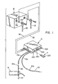
- FIGURE 1 illustrates a connection of the preferred embodiment of the present invention wherein the anti-theft control unit 10 is connected in a system including a standard motor vehicle battery 12 and an ignition coil 14.
- Battery cables 20, 22 provide power to coil 14 for the purpose of operating the motor vehicle.
- control unit 10 includes a microprocessor and is powered by leads 30, 32 form standard battery 12. Connection of control unit 10 on a motor vehicle includes mounting the unit by bolts in an inaccessible location.
- the battery cable 20 is then cut adjacent coil 14 to provide spaced ends 20a, 20b. These spaced ends are provided with electrical fasteners and to leads 10a, 10b forming the output of control unit 10, as shown in FIGURE 1.
- unit 10 is easily installed. This installation can be done by a person with relatively minor knowledge of the electrical system of a motor vehicle.
- Battery cables 20, 22 are removed from battery terminals 12a, 12b for connection of power leads 30, 32. In this manner, the anti-theft device, constituting control unit 10, is easily installed in a motor vehicle with very few tools and a minor amount of technical knowledge.
- Transmitter T is carried by an authorized operator of the motor vehicle onto which unit 10 is mounted and includes an antenna 50 and a clip 52 for mounting the transmitter onto the person of the authorized operator.
- transmitter T could be carried in the clothing of the operator or otherwise carried by the operator to maintain signal S transmitting to unit 10 when the transmitter T is in the vicinity of the motor vehicle.
- Vicinity is a relative term and is meant to mean preferably approximately 5-20 feet or generally less than about 50 feet from the motor vehicle. After the transmitter T is beyond the vicinity of the vehicle, signal S is no longer available for detection by unit 10.
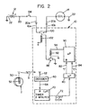
- the vehicle mounted unit 10 includes a decoder 60 having an antenna 62 and an output 64.
- Signal S has a unique multiple bit digital signal which is transmitted serially and periodically to unit 10. Only this unique coded signal can be recognized and acknowledged by decoder 60. This concept is standard digital practice.
- a signal having the desired unique code set into decoder 60 is received by the decoder, a signal is transmitted by the output 64 to a reset timer 70.
- the timer is formed as part of the microprocessor used in control unit 10.
- the timer 70 could be a reset timer formed of discrete circuit components.
- the timer in accordance with the preferred embodiment of the invention, produces a logic 1 in output 72 when the timer expires without a reset signal in line 64.
- Expiration time of timer 70 is, in practice, 2.0 minutes. Consequently, if a signal in line 64 is not received within 2.0 minutes, the output line 72 shifts from a first condition allowing operation of the motor vehicle to a second condition indicated as a logic 1. This second condition inhibits operation of the motor vehicle in accordance with the present invention.
- Output 72 is directed to stage 80 of the microprocessor which identifies whether the motor vehicle is to be operated.
- a logic 0 in line 72 is a reset signal resetting stage 90 of the microprocessor by a logic 1 in line 82.
- stage 80 has a logic 1 output in line 82 which resets stage 90 of the microprocessor in unit 10.
- a logic 1 appears in line 84 instead of a logic 1 in line 82.
- a logic 0 appears in line 82
- a logic 1 appears in line 84 when a logic 1 appears in line 72.
- This digital condition initiates the stall sequence described in more detail in FIGURE 3 and implemented in stage 90 of the microprocessor.
- the stall sequence as will be described later, opens and closes the power to coil 14. This is done in the microprocessor.
- This function is schematically illustrated as a relay RE having a coil 92 controlled by output 94 from microprocessor stage 90.
- Microprocessor stage 90 is the inhibit arrangement for inhibiting the operation of the motor vehicle by gradually stalling the motor vehicle through operation of stage 90 in the manner illustrated in FIGURE 3.
- Relay RE is normally closed when the vehicle is to be operated.
- Relay RE operates breaker 100 through a coil 102 adjacent lines 20a, 20b.
- This power breaker 100 is mounted, in the preferred embodiment, within control unit 10. Of course, it could be a separate, discrete component outside unit 10 if desired.
- Breaker 100 is normally opened as shown in FIGURE 2. When relay RE is closed, breaker 100 is closed to allow operation of the coil 14 as long as ignition switch SW is closed.
- a reset signal periodically appears in line 64.
- This maintains reset timer stage 70 in its reset condition with a logic 0 in line 72.
- a logic 1 appears in line 82 from stage 80 to maintain the stall sequence in stage 90 of the microprocessor in the reset condition.
- a logic 1 appears on line 94 closing relay RE and, thus, closing breaker 100.
- the motor vehicle operates normally.
- Reset timer stage 70 times out shifting output 72 from a first condition allowing operation of the vehicle to a second condition inhibiting operation of the vehicle.
- This second condition is represented by logic 1 in line 72, which logic causes a logic 1 to appear in line 84.
- the stall sequence as disclosed in FIGURE 3, ultimately causes a logic 1 to appear in line 94.
- This permanent or sustained logic 1 opens relay RE.
- breaker 100 is opened since it assumes its normal position.
- a normally opened breaker could be employed if desired.
- the normal position would be indicative of a logic 1 or second condition in line 72.
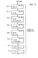
- the stall sequence of stage 90 is schematically illustrated in FIGURE 3 wherein a logic 1 in line 84 commences the sequence for stalling the vehicle gradually.
- block 120 creates a logic 0 in line 94. This occurs for 65.6 milliseconds.
- Such signal opens breaker 100 as shown in FIGURE 2 for a very short period of time.
- a logic 1 appears in line 94 for 10.0 seconds.
- coil 14 can operate normally for 10 seconds.
- a logic 0 appears in block 120a for a time X 1 . This time is greater than 65.6 milliseconds.
- a logic 1 appears in line 94 causing coil 14 to be activated for 9.5 seconds.
- This sequence between block 120 and block 122 continues gradually increasing the time that the coil is inactive and gradually decreasing the time when the coil is active, until reaching blocks 130, 132 where the logic 0 remains on line 94 and breaker 100 is maintained opened.
- the stall sequence could take a variety of configurations. By using the stall sequence, the vehicle shuts down gradually. The vehicle gradually loses power until the vehicle can no longer operate. This allows brakes, power steering, and other accessories to be operative for the purposes of steering the vehicle off the roadway and gradually stopping the vehicle. The person stealing the vehicle and leaving transmitter T behind merely experiences a gradual shut-down of the motor vehicle. This is sufficient to allow parking the vehicle at the side of the roadway. Under no circumstance can the vehicle be moved further.
- the vehicle After two minutes without the transmitter in the vicinity of unit 10, the vehicle starts into the stall sequence.
- the stall sequence in practice, lasts 1.0 minutes. Since the vehicle is normally driven away quite rapidly, the person commandeering the vehicle in a high tension situation will be many blocks from the victim before the vehicle is stalled.
- the present invention is particularly applicable for preventing hijacking of a vehicle by stalling the vehicle at a remote location from the actual hijacking location.
- the personal identification device or transmitter T is removed.
- unit 10 to shut down the motor vehicle in the parked unattended condition. Consequently, device 10 also performs an anti-theft prevention function.
- unit 10 can be combined with a device for sensing whether the alternator is operating to know whether the vehicle is operating or parked. In normal entry, the transmitter signal is received by unit 10 and the alternator is off. In this instance, an auxiliary system is employed for unlocking the doors and enabling the ignition system by unit 10.
- device 10 enables and maintains the ignition system as illustrated in FIGURE 2.
- the PID or transmitter is removed.
- the alternator had been operating; therefore, after two minutes, the ignition is progressively shut down in accordance with the stall sequence of FIGURE 3. It is possible to apply auxiliary accessories to lock the doors in this situation. If the automobile is hijacked, which indicates a removal of the transmitter while the alternator is operating, the vehicle waits for two minutes before it is stalled in accordance with the sequence of FIGURE 3.
- FIGURE 4 in some instances it is necessary to operate control unit 10 by more than one transmitter.
- the several transmitters could be for use with other products manufactured and/or distributed by the entity distributing the present invention.
- Each of these transmitters T A , T B , T C and T D is illustrated in FIGURE 4.
- Four decoders 200-206 are provided to give periodic signals in line 64 upon receipt of the specific signal for which the decoders are each set.
- a decoder will create an output in one of the lines 200a, 202a, 204a or 206a according to the transmitter in the vicinity of unit 10.
- a key decoder 210 identifies the proper key K inserted into one of the key ports 120, 122, 124 or 126 as shown in FIGURES 1 and 5.
- Key K inserted into port 120 is first identified as a proper key by decoder 210. If the proper key is present, a signal light 230 is activated and a coded signal is received on line 240 from a particular one of the several transmitters or personal identification devices, as shown in FIGURE 4. By using the proper key K an enable signal appears on one of the lines 250, 252, 254, 256 to enable one of the decoders 200-206. The enable lines condition the decoders for receipt of the next decoded signal and for setting of the decoder to that signal code. When the decoder has been programmed with a new code, light 230 is activated indicating that there has been a coding of the unit 10 to the particular transmitter in the vicinity of the motor vehicle. Unit 10 operates in accordance with the previous discussion. As one of the transmitters having a code set into one of the decoders 200-206 is brought into the vicinity of the vehicle, the signal S causes periodic pulses in line 64.
- FIGURE 6 Another key arrangement is illustrated in FIGURE 6, wherein key K' has physical decoding dimples or recesses and a light 230' powered by leads 230a, 230b.
- a key is placed into one of the ports shown in FIGURE 5 which activates a selected one of the decoders 200-206 corresponding to the port receiving the key.
- the key must be identified with a particular unit 10 by the code on the key.
- the decoder corresponding to the key port is loaded with the particular code of one of the transmitters shown in FIGURE 4. Consequently, several transmitters can be employed for operating the anti-theft device constructed in accordance with the present invention.
- the small personal identification unit or transmitter T is illustrated in FIGURE 7 wherein the first stage is the "message” stage which creates a continuous signal in line 300a. This stage 300 could also be employed for use with the key K for learning the particular code of transmitter T. Under normal conditions, continuous power is applied through line 300a to the pulse timer 302. This pulse timer creates a signal in line 302a each 10.1 seconds. This signal is converted to the desired unique coded signal by encoder 304 to produce a series of binary signals which are directed to the 100 kHz oscillator 306. The output of the oscillator is a series of small or long pulses indicative of the logic 0 and a logic 1, respectively, of a binary coded signal.
- the coded signal is directed through line 306a to the antenna driver isolator 308 so that each 10.1 seconds an electromagnetic coded signal unique to transmitter T is transmitted from antenna 310, illustrated in FIGURE 2 as antenna 50.
- the signal on antenna 310 is provided with a carrier having a frequency of 418 MHz.
- the resulting signal is a 100 kHz decoded serial signal with a 418 MHz carrier.
- This signal occurs each 10.1 seconds to reset timing stage 70 periodically as transmitter T is in the vicinity of unit 10 on the motor vehicle being controlled. It is possible that other transmitting devices could be employed to periodically reset the timer 70.
- the transmitter T as illustrated in FIGURE 5 produces signal S as shown in FIGURE 8 and is the preferred embodiment. This signal has a series of binary numbers defined by short pulses S1, S3 and long pulses S2 and S4.
Landscapes
- Engineering & Computer Science (AREA)
- Mechanical Engineering (AREA)
- Automation & Control Theory (AREA)
- Human Computer Interaction (AREA)
- Transportation (AREA)
- Lock And Its Accessories (AREA)
- Burglar Alarm Systems (AREA)
- Protection Of Generators And Motors (AREA)
- Lens Barrels (AREA)
- Transition And Organic Metals Composition Catalysts For Addition Polymerization (AREA)
Applications Claiming Priority (3)
| Application Number | Priority Date | Filing Date | Title |
|---|---|---|---|
| US08/014,560 US5604384A (en) | 1993-02-08 | 1993-02-08 | Anti-theft device for motor vehicle |
| US14560 | 1993-02-08 | ||
| EP94101934A EP0610902B1 (de) | 1993-02-08 | 1994-02-08 | Diebstahlschutzvorrichtung, insbesondere für Kraftfahrzeuge |
Related Parent Applications (1)
| Application Number | Title | Priority Date | Filing Date |
|---|---|---|---|
| EP94101934A Division EP0610902B1 (de) | 1993-02-08 | 1994-02-08 | Diebstahlschutzvorrichtung, insbesondere für Kraftfahrzeuge |
Publications (3)
| Publication Number | Publication Date |
|---|---|
| EP1380479A2 true EP1380479A2 (de) | 2004-01-14 |
| EP1380479A3 EP1380479A3 (de) | 2004-01-21 |
| EP1380479B1 EP1380479B1 (de) | 2009-04-29 |
Family
ID=21766205
Family Applications (2)
| Application Number | Title | Priority Date | Filing Date |
|---|---|---|---|
| EP94101934A Expired - Lifetime EP0610902B1 (de) | 1993-02-08 | 1994-02-08 | Diebstahlschutzvorrichtung, insbesondere für Kraftfahrzeuge |
| EP03022091A Expired - Lifetime EP1380479B1 (de) | 1993-02-08 | 1994-02-08 | Diebstahlschutzvorrichtung, insbesondere für Kraftfahrzeuge |
Family Applications Before (1)
| Application Number | Title | Priority Date | Filing Date |
|---|---|---|---|
| EP94101934A Expired - Lifetime EP0610902B1 (de) | 1993-02-08 | 1994-02-08 | Diebstahlschutzvorrichtung, insbesondere für Kraftfahrzeuge |
Country Status (13)
| Country | Link |
|---|---|
| US (2) | US5604384A (de) |
| EP (2) | EP0610902B1 (de) |
| JP (1) | JP2838478B2 (de) |
| KR (1) | KR0160318B1 (de) |
| AT (2) | ATE430072T1 (de) |
| AU (1) | AU666601B2 (de) |
| CA (1) | CA2114612C (de) |
| DE (2) | DE69435207D1 (de) |
| DK (1) | DK1380479T3 (de) |
| ES (2) | ES2213145T3 (de) |
| NO (1) | NO940394L (de) |
| PH (1) | PH30844A (de) |
| UY (1) | UY24095A1 (de) |
Families Citing this family (56)
| Publication number | Priority date | Publication date | Assignee | Title |
|---|---|---|---|---|
| DE4440975C2 (de) * | 1994-11-17 | 1997-06-12 | Daimler Benz Ag | Fremdnutzungsschutzeinrichtung für ein Kraftfahrzeug |
| IT1276081B1 (it) * | 1995-11-06 | 1997-10-24 | Ducati Energia Spa | Accensione elettronica con antifurto combinato |
| US5811886A (en) * | 1995-12-06 | 1998-09-22 | Alertcall, Inc. | Anti-carjacking apparatus |
| JP3292025B2 (ja) * | 1996-02-27 | 2002-06-17 | 日産自動車株式会社 | 車両用キーレスシステムの自動ロック装置 |
| US5977654A (en) * | 1997-09-25 | 1999-11-02 | Johnson Controls Technology Company | Anti-theft System for disabling a vehicle engine that includes a multi-contact switch for disconnecting the battery and loading the vehicle electrical system |
| US5965954A (en) * | 1997-09-25 | 1999-10-12 | Johnson Controls Technology Company | Anti-theft system for disabling a vehicle engine |
| FR2771534B1 (fr) * | 1997-11-24 | 2000-06-09 | Valeo Systemes De Fermetures | Vehicule automobile equipe d'un systeme de detection de l'approche d'un utilisateur |
| US5937823A (en) * | 1998-01-05 | 1999-08-17 | Reeder; Allan | Safely disabling a land vehicle using a selective call radio signal |
| US6265787B1 (en) * | 1999-01-28 | 2001-07-24 | Richard T. Downey | Vehicle anti-theft system |
| EP1028041A3 (de) * | 1999-02-10 | 2001-10-24 | Michael Martin Machala | Verfahren und Vorrichtung zum elektronischen Verzögern oder Anhalten von Fahrzeugen |
| US20030169150A1 (en) * | 1999-03-23 | 2003-09-11 | Brendzel Henry Tzvi | Arrangement for prevention of motor vehicle thefts |
| US6531955B1 (en) * | 1999-03-23 | 2003-03-11 | Henry Tzvi Brendzel | Arrangement for prevention of motor vehicle thefts |
| US6109076A (en) * | 1999-05-06 | 2000-08-29 | Master Lock Company | Automobile and airbag anti-theft device |
| US6819009B2 (en) | 2000-04-12 | 2004-11-16 | Carl Ellingsworth | Method and apparatus for preventing unauthorized access to a vehicle |
| DE10059991A1 (de) * | 2000-12-02 | 2002-06-06 | Bosch Gmbh Robert | Vorrichtung zum schlüssellosen Betrieb eines Kraftfahrzeugs |
| US7071819B2 (en) | 2001-07-05 | 2006-07-04 | Honda Giken Kogyo Kabushiki Kaisha | Remote control lock operation system for vehicles |
| US6679089B2 (en) | 2001-10-19 | 2004-01-20 | Robert A. Vito | Type of automobile anti-theft device |
| USD493692S1 (en) | 2001-10-19 | 2004-08-03 | Robert A. Vito | Lock assembly component |
| USD493354S1 (en) | 2001-10-19 | 2004-07-27 | Robert A. Vito | Lock assembly component |
| JP3847140B2 (ja) * | 2001-10-30 | 2006-11-15 | 株式会社モリック | 乗り物における盗難防止装置 |
| USD465721S1 (en) | 2001-12-07 | 2002-11-19 | Robert A. Vito | Anti-theft device |
| US6460385B1 (en) | 2001-12-07 | 2002-10-08 | Robert A. Vito | Column lock device |
| USD458529S1 (en) | 2001-12-07 | 2002-06-11 | Robert A. Vito | Anti-theft device |
| US6516642B1 (en) | 2001-12-07 | 2003-02-11 | Robert A. Vito | Column security device |
| CA2491662C (en) * | 2002-07-12 | 2015-11-24 | Privaris, Inc. | Personal authentication software and systems for travel privilege assignation and verification |
| US6857496B2 (en) * | 2002-09-03 | 2005-02-22 | Trw Inc. | Vehicle steering apparatus with anti-steer security device |
| US7973649B2 (en) * | 2002-09-10 | 2011-07-05 | Lojack Operating Company Lp | Method of an apparatus for sensing the unauthorized movement of vehicles and the like and generating an alarm or warning of vehicle theft |
| ES2207411B1 (es) * | 2002-11-11 | 2005-02-01 | Javier Lopez Berlanga | Dispositivo antirrobo de vehiculos. |
| GB2396238B (en) * | 2002-12-11 | 2006-05-24 | Nippon Yusoki Co Ltd | Unqualified person driving prevention apparatus for vehicle |
| EP1606149B1 (de) * | 2003-03-25 | 2014-05-07 | Milton Thompson | Sicherheitsberechtigungssystem |
| GB2399924A (en) * | 2003-03-25 | 2004-09-29 | Milton Thompson | Security authorisation system requires wireless communication link between complentary parts |
| WO2004096603A2 (en) * | 2003-04-25 | 2004-11-11 | Jackson Donald Wqyne | Anti-theft device for motorized vehicles |
| US7551064B2 (en) | 2003-08-13 | 2009-06-23 | Idas Informations-Daten- und Automationssysteme GmbH | Method and device for securing a vehicle against theft |
| ATE413993T1 (de) * | 2003-08-13 | 2008-11-15 | Idas Informations Daten Und Au | Verfahren und vorrichtung zur sicherung eines fahrzeugs gegen diebstahl |
| CN1299937C (zh) * | 2003-12-30 | 2007-02-14 | 厦门雅迅网络股份有限公司 | 一种汽车防盗报警系统自动布防撤防的方法 |
| EP1730005B1 (de) * | 2004-01-12 | 2008-02-27 | LoJack Corporation | Detektieren einer fahrzeugbewegung |
| US20060238299A1 (en) * | 2005-04-22 | 2006-10-26 | Downey Richard T | Electrical enabling device |
| CA2509804A1 (fr) * | 2005-06-15 | 2006-12-15 | Kolombo Technologies Ltee | Systeme de gestion et d'intervention a distance et en temps reel pour vehicules industriels de transport routier |
| WO2007007640A1 (ja) | 2005-07-13 | 2007-01-18 | Komatsu Utility Co., Ltd. | 運転許可制御装置およびそれを搭載した機械 |
| JP4783643B2 (ja) * | 2006-02-06 | 2011-09-28 | 株式会社小松製作所 | 移動体監視装置および移動体監視システム |
| JP4835239B2 (ja) * | 2006-04-06 | 2011-12-14 | スズキ株式会社 | 自動二輪車 |
| JP2011126293A (ja) * | 2008-03-28 | 2011-06-30 | Yamaha Motor Electronics Co Ltd | 盗難抑止装置 |
| DE102009011088A1 (de) * | 2009-03-03 | 2010-09-09 | Volkswagen Ag | Verfahren und Vorrichtung zur Steuerung einer Fahrzeugbewegungsmöglichkeit und/oder einer Verschlussvorrichtung |
| KR101927217B1 (ko) * | 2011-05-03 | 2018-12-10 | 엘지이노텍 주식회사 | 도어락을 위한 스마트키 시스템의 제어 방법 |
| US20130033369A1 (en) * | 2011-08-02 | 2013-02-07 | Burnett Ronald A | Electronic anti-theft apparatus and system for vehicles |
| ITGE20130026A1 (it) | 2013-02-28 | 2014-08-29 | Salvatore Guarneri | Dispositivo di allarme per veicoli |
| KR20160032004A (ko) * | 2013-04-23 | 2016-03-23 | 카나리 컨넥트 인코퍼레이티드 | 보안 및/또는 감시 장치 및 시스템 |
| DE102013020333A1 (de) * | 2013-12-04 | 2015-06-11 | Daimler Ag | System und Verfahren zum Stilllegen eines unrechtmäßig benutzten Fahrzeuges |
| US10239476B2 (en) * | 2013-12-23 | 2019-03-26 | Lippert Components, Inc. | System for inhibiting operation of a vehicle-based device while the vehicle is in motion |
| US9663113B2 (en) * | 2014-10-06 | 2017-05-30 | Preventext Llc | Integrated vehicle monitoring and control |
| CN106740683B (zh) * | 2017-03-03 | 2019-05-17 | 铁将军汽车电子股份有限公司 | 基于can总线的车辆解锁方法及其系统 |
| US11194350B2 (en) * | 2018-10-17 | 2021-12-07 | International Business Machines Corporation | Navigation of an autonomous vehicle for following individuals |
| US20200231119A1 (en) * | 2019-01-22 | 2020-07-23 | Ali Mahmood | Anti-Theft Vehicle Shutdown Kit |
| DE102019131946A1 (de) * | 2019-11-26 | 2021-05-27 | Bayerische Motoren Werke Aktiengesellschaft | Verfahren zum Betreiben eines Fahrzeugs, Vorrichtung und Fahrzeug |
| US12474714B2 (en) | 2021-06-10 | 2025-11-18 | Stop Technologies, Inc. | System and methodology that facilitates taking control of a vehicle from a remote device |
| JP2025034745A (ja) * | 2023-08-31 | 2025-03-13 | スズキ株式会社 | 車両の盗難防止システム |
Family Cites Families (55)
| Publication number | Priority date | Publication date | Assignee | Title |
|---|---|---|---|---|
| US3646515A (en) * | 1970-03-02 | 1972-02-29 | Frank Vodehnal | Vehicular safety and remote control system |
| US3665386A (en) * | 1970-12-18 | 1972-05-23 | Dynamics Corp America | Anti-hijack system for vehicles |
| US3788422A (en) * | 1972-10-27 | 1974-01-29 | Gmc Co | Anti-theft system including a pushbutton electronic combination ignition lock and transmission shift control |
| US4004273A (en) * | 1975-08-28 | 1977-01-18 | Kalogerson Thomas A | Engine speed responsive anti-theft device for vehicle |
| US4023138A (en) * | 1975-11-17 | 1977-05-10 | Joseph Ballin | Vehicle theft prevention system |
| US4101873A (en) * | 1976-01-26 | 1978-07-18 | Benjamin Ernest Anderson | Device to locate commonly misplaced objects |
| US4143368A (en) * | 1977-12-05 | 1979-03-06 | General Motors Corporation | Vehicle operator security system |
| FR2423015A1 (fr) * | 1978-04-14 | 1979-11-09 | M B Ste Civile | Dispositifs de telecommande automatique de l'enclenchement et de la neutralisation d'une alarme |
| US4292620A (en) * | 1979-06-13 | 1981-09-29 | Pagane Warren H | Fuel level monitoring engine control and vehicle theft inhibiting device |
| US4260982A (en) * | 1979-10-25 | 1981-04-07 | Debenedictis Angelo P | Pulse code modulation responsive alarm system |
| DE3048861A1 (de) * | 1980-07-14 | 1982-07-15 | John L. Denver Col. Royster | Sicherheitssystem |
| FR2493246A1 (fr) * | 1980-11-03 | 1982-05-07 | Prost Albert | Appareil automatique de blocage et deblocage des ouvertures, associes a la mise en oeuvre et a l'arret d'un systeme de securite |
| JPS58174357U (ja) * | 1982-05-18 | 1983-11-21 | 橋爪 外信 | 自動車の盗難防止装置 |
| US4452197A (en) * | 1982-08-11 | 1984-06-05 | Weber Harold J | Vehicle anti-theft ignition foiling device |
| US4598275A (en) * | 1983-05-09 | 1986-07-01 | Marc Industries Incorporated | Movement monitor |
| US4754255A (en) * | 1984-03-12 | 1988-06-28 | Sanders Rudy T | User identifying vehicle control and security device |
| US4675656A (en) * | 1984-03-16 | 1987-06-23 | Narcisse Bernadine O | Out-of-range personnel monitor and alarm |
| US4598272A (en) * | 1984-08-06 | 1986-07-01 | Cox Randall P | Electronic monitoring apparatus |
| JPS61215457A (ja) * | 1985-03-22 | 1986-09-25 | Aisin Seiki Co Ltd | 車上イグニツシヨン装置 |
| JPS61161056U (de) * | 1985-03-28 | 1986-10-06 | ||
| JPH0727508B2 (ja) * | 1985-07-23 | 1995-03-29 | 富士通株式会社 | バスオ−ダの滞留制御方式 |
| JPS6222170U (de) * | 1985-07-25 | 1987-02-10 | ||
| JPS6237479A (ja) * | 1985-08-12 | 1987-02-18 | 日産自動車株式会社 | 無線式施解錠制御装置 |
| JPS6271070U (de) * | 1985-10-24 | 1987-05-06 | ||
| GR861382B (en) * | 1985-11-13 | 1987-02-06 | Pelta Elettronica S P A | System for remote control of the antitheft protection devices of a property |
| JPS62203854A (ja) * | 1986-03-03 | 1987-09-08 | Matsushita Electric Works Ltd | 自動車用カ−ドシステム |
| JPS63130900U (de) * | 1987-02-16 | 1988-08-26 | ||
| US4785291A (en) * | 1987-03-06 | 1988-11-15 | Hawthorne Candy C | Distance monitor especially for child surveillance |
| US4987406A (en) * | 1987-04-13 | 1991-01-22 | Reid Philip L | Security system for electrical appliances and other items with electrical circuitry |
| JPS6474145A (en) * | 1987-09-17 | 1989-03-20 | Nippon Kikaku Kk | Driver's license inserting engine starting control device |
| US4898010A (en) * | 1987-10-28 | 1990-02-06 | Nissan Motor Company, Limited | Keyless entry system for automotive vehicles |
| JPH01165750U (de) * | 1988-05-13 | 1989-11-20 | ||
| US4942393A (en) * | 1988-05-27 | 1990-07-17 | Lectron Products, Inc. | Passive keyless entry system |
| JPH0223383A (ja) * | 1988-07-12 | 1990-01-25 | Japan Metaritsuku:Kk | 複写機を用いた秘密漏洩防止システムと複写用紙 |
| JPH0291864A (ja) * | 1988-09-27 | 1990-03-30 | Nec Ibaraki Ltd | 磁気ディスク装置 |
| US4924206A (en) * | 1988-12-05 | 1990-05-08 | Ayers Robert F | Car security system and method |
| US4866296A (en) * | 1988-12-09 | 1989-09-12 | Thomas Stephen R | Circuit interrupt system |
| JPH0291864U (de) * | 1988-12-29 | 1990-07-20 | ||
| US4992670A (en) * | 1989-04-03 | 1991-02-12 | Pastor David E | Ignition disabling anti-theft device |
| JPH02299955A (ja) * | 1989-05-15 | 1990-12-12 | Motohiro Gotanda | 自動車の盗難防止装置 |
| DE4019478A1 (de) * | 1989-06-20 | 1991-01-10 | Honda Motor Co Ltd | Elektrische spannungsversorgungs-kontrolleinheit fuer ein kraftfahrzeug |
| JPH0386869A (ja) * | 1989-08-30 | 1991-04-11 | Kanebo Ltd | キナゾリン誘導体の製造法 |
| JP2507815B2 (ja) * | 1989-11-02 | 1996-06-19 | 日産自動車株式会社 | 車両用キ―レス制御装置 |
| JPH03148352A (ja) * | 1989-11-02 | 1991-06-25 | Nissan Motor Co Ltd | 車両用キーレス制御装置 |
| JP2593566B2 (ja) * | 1989-12-18 | 1997-03-26 | アルパイン株式会社 | 車載用セキュリティ装置 |
| JPH03208974A (ja) * | 1990-01-10 | 1991-09-12 | Oki Electric Ind Co Ltd | 自動車の施錠装置 |
| US5229375A (en) * | 1990-08-01 | 1993-07-20 | Scripps Clinic And Research Foundation | Phosphene oxide-terminated allene-ene-yne dna-cleaving, antitumor and antibiotic molecules |
| IT221193Z2 (it) * | 1990-08-10 | 1994-02-16 | Girotto Pietro | Dispositivo di comando automatico di un impianto antifurto |
| DE4030880A1 (de) * | 1990-09-29 | 1992-04-09 | Fischer Lagertechnik | Verfahren zur sicherung von elektro-transportgeraeten und anordnung zur durchfuehrung des verfahrens |
| US5132660A (en) * | 1991-01-09 | 1992-07-21 | Nutek Corporation | Vehicle security system |
| JPH04331647A (ja) * | 1991-04-30 | 1992-11-19 | Honda Motor Co Ltd | 車両用電源制御装置 |
| US5412370A (en) * | 1992-10-23 | 1995-05-02 | Berman; Leonard C. | Car theft prevention device |
| US5444430A (en) * | 1993-01-04 | 1995-08-22 | Mcshane; Richard | Motor vehicle security system |
| US5349329B1 (en) * | 1993-05-07 | 1996-09-10 | Ideaz International Inc | Vehicle security apparatus and method |
| JP3086869U (ja) * | 2001-12-21 | 2002-07-05 | ユーザー株式会社 | フロアマット |
-
1993
- 1993-02-08 US US08/014,560 patent/US5604384A/en not_active Expired - Lifetime
-
1994
- 1994-01-14 PH PH47616A patent/PH30844A/en unknown
- 1994-01-31 CA CA002114612A patent/CA2114612C/en not_active Expired - Fee Related
- 1994-02-03 AU AU54907/94A patent/AU666601B2/en not_active Ceased
- 1994-02-04 JP JP4299994A patent/JP2838478B2/ja not_active Expired - Fee Related
- 1994-02-05 KR KR1019940002146A patent/KR0160318B1/ko not_active Expired - Fee Related
- 1994-02-07 NO NO940394A patent/NO940394L/no not_active Application Discontinuation
- 1994-02-08 EP EP94101934A patent/EP0610902B1/de not_active Expired - Lifetime
- 1994-02-08 ES ES94101934T patent/ES2213145T3/es not_active Expired - Lifetime
- 1994-02-08 DE DE69435207T patent/DE69435207D1/de not_active Expired - Lifetime
- 1994-02-08 ES ES03022091T patent/ES2326524T3/es not_active Expired - Lifetime
- 1994-02-08 DK DK03022091T patent/DK1380479T3/da active
- 1994-02-08 DE DE69433417T patent/DE69433417T2/de not_active Expired - Lifetime
- 1994-02-08 AT AT03022091T patent/ATE430072T1/de not_active IP Right Cessation
- 1994-02-08 EP EP03022091A patent/EP1380479B1/de not_active Expired - Lifetime
- 1994-02-08 AT AT94101934T patent/ATE256582T1/de not_active IP Right Cessation
-
1995
- 1995-08-07 US US08/512,065 patent/US6400042B1/en not_active Expired - Fee Related
- 1995-11-21 UY UY24095A patent/UY24095A1/es not_active IP Right Cessation
Also Published As
| Publication number | Publication date |
|---|---|
| DE69433417D1 (de) | 2004-01-29 |
| US5604384A (en) | 1997-02-18 |
| ATE430072T1 (de) | 2009-05-15 |
| PH30844A (en) | 1997-11-05 |
| CA2114612A1 (en) | 1994-08-09 |
| EP0610902A3 (de) | 1995-07-05 |
| JPH06340245A (ja) | 1994-12-13 |
| EP1380479B1 (de) | 2009-04-29 |
| DE69433417T2 (de) | 2004-10-21 |
| KR940019534A (ko) | 1994-09-14 |
| NO940394L (no) | 1994-08-09 |
| UY24095A1 (es) | 1996-01-15 |
| AU5490794A (en) | 1994-09-22 |
| CA2114612C (en) | 1998-09-22 |
| DK1380479T3 (da) | 2009-08-24 |
| AU666601B2 (en) | 1996-02-15 |
| ATE256582T1 (de) | 2004-01-15 |
| NO940394D0 (no) | 1994-02-07 |
| US6400042B1 (en) | 2002-06-04 |
| ES2326524T3 (es) | 2009-10-14 |
| EP0610902B1 (de) | 2003-12-17 |
| KR0160318B1 (ko) | 1998-12-15 |
| DE69435207D1 (de) | 2009-06-10 |
| EP1380479A3 (de) | 2004-01-21 |
| JP2838478B2 (ja) | 1998-12-16 |
| ES2213145T3 (es) | 2004-08-16 |
| EP0610902A2 (de) | 1994-08-17 |
Similar Documents
| Publication | Publication Date | Title |
|---|---|---|
| EP1380479B1 (de) | Diebstahlschutzvorrichtung, insbesondere für Kraftfahrzeuge | |
| US5382948A (en) | Vehicular security system with remote signalling for auto carjacking functions | |
| KR940002682B1 (ko) | 사용자 식별이 가능한 차량용 도난방지시스템 | |
| US6028505A (en) | Electronic vehicle security system with remote control | |
| US5307048A (en) | Vehicle security system including an anti-carjacking system | |
| US6781507B1 (en) | Remote start, passive anti theft security system | |
| KR100345886B1 (ko) | 차량경보시스템 | |
| US5811886A (en) | Anti-carjacking apparatus | |
| US20030222757A1 (en) | Countermeasure system and method for vehicle passive entry system | |
| US7859129B2 (en) | Vehicle antitheft device and control method of a vehicle | |
| US5412378A (en) | Antitheft protection of devices | |
| US5473200A (en) | Frequency modulation digital code anti-theft system | |
| US5850173A (en) | Vehicle alarm system | |
| US5539377A (en) | Vehicle security system | |
| GB2286634A (en) | Vehicle theft prevention system | |
| US5760680A (en) | Vehicle security device | |
| HK1010713A (en) | Anti-theft device especially for motor vehicles | |
| US4297674A (en) | Passive security device | |
| RU2179122C1 (ru) | Способ предотвращения несанкционированного пользования транспортным средством | |
| CN1125671A (zh) | 汽车防盗装置 | |
| KR100501363B1 (ko) | 차량 도난 방지 장치 | |
| WO1993004899A1 (en) | Passive vehicular theft deterrent system and method | |
| KR19980060122A (ko) | 화상전송을 이용한 차량도난 방지장치 | |
| CA2142500A1 (en) | Anti-theft or anti-hijacking device for vehicles | |
| HUP0201036A2 (hu) | Rendszer és eszköz gépjármżvek lopás, illetve jogosulatlan használat elleni védelmére |
Legal Events
| Date | Code | Title | Description |
|---|---|---|---|
| PUAI | Public reference made under article 153(3) epc to a published international application that has entered the european phase |
Free format text: ORIGINAL CODE: 0009012 |
|
| PUAL | Search report despatched |
Free format text: ORIGINAL CODE: 0009013 |
|
| 17P | Request for examination filed |
Effective date: 20031002 |
|
| AC | Divisional application: reference to earlier application |
Ref document number: 0610902 Country of ref document: EP Kind code of ref document: P |
|
| AK | Designated contracting states |
Kind code of ref document: A2 Designated state(s): AT BE CH DE DK ES FR GB GR IE IT LI LU MC NL PT SE |
|
| AK | Designated contracting states |
Kind code of ref document: A3 Designated state(s): AT BE CH DE DK ES FR GB GR IE IT LI LU MC NL PT SE |
|
| XX | Miscellaneous (additional remarks) |
Free format text: THIS APPLICATION WAS FILED ON 02-10-2003 AS A DIVISIONAL APPLICATION TO THE APPLICATION MENTIONED UNDER INID CODE 62. |
|
| AKX | Designation fees paid |
Designated state(s): AT BE CH DE DK ES FR GB GR IE IT LI LU MC NL PT SE |
|
| 17Q | First examination report despatched |
Effective date: 20050419 |
|
| GRAP | Despatch of communication of intention to grant a patent |
Free format text: ORIGINAL CODE: EPIDOSNIGR1 |
|
| GRAS | Grant fee paid |
Free format text: ORIGINAL CODE: EPIDOSNIGR3 |
|
| GRAA | (expected) grant |
Free format text: ORIGINAL CODE: 0009210 |
|
| AC | Divisional application: reference to earlier application |
Ref document number: 0610902 Country of ref document: EP Kind code of ref document: P |
|
| AK | Designated contracting states |
Kind code of ref document: B1 Designated state(s): AT BE CH DE DK ES FR GB GR IE IT LI LU MC NL PT SE |
|
| REG | Reference to a national code |
Ref country code: GB Ref legal event code: FG4D |
|
| XX | Miscellaneous (additional remarks) |
Free format text: THIS APPLICATION WAS FILED ON 02-10-2003 AS A DIVISIONAL APPLICATION TO THE APPLICATION MENTIONED UNDER INID CODE 62. |
|
| REG | Reference to a national code |
Ref country code: CH Ref legal event code: EP |
|
| REF | Corresponds to: |
Ref document number: 69435207 Country of ref document: DE Date of ref document: 20090610 Kind code of ref document: P |
|
| REG | Reference to a national code |
Ref country code: IE Ref legal event code: FG4D |
|
| REG | Reference to a national code |
Ref country code: DK Ref legal event code: T3 |
|
| REG | Reference to a national code |
Ref country code: GR Ref legal event code: EP Ref document number: 20090401879 Country of ref document: GR Ref country code: SE Ref legal event code: TRGR |
|
| REG | Reference to a national code |
Ref country code: CH Ref legal event code: NV Representative=s name: E. BLUM & CO. AG PATENT- UND MARKENANWAELTE VSP |
|
| NLV1 | Nl: lapsed or annulled due to failure to fulfill the requirements of art. 29p and 29m of the patents act | ||
| REG | Reference to a national code |
Ref country code: ES Ref legal event code: FG2A Ref document number: 2326524 Country of ref document: ES Kind code of ref document: T3 |
|
| PG25 | Lapsed in a contracting state [announced via postgrant information from national office to epo] |
Ref country code: PT Free format text: LAPSE BECAUSE OF FAILURE TO SUBMIT A TRANSLATION OF THE DESCRIPTION OR TO PAY THE FEE WITHIN THE PRESCRIBED TIME-LIMIT Effective date: 20090829 Ref country code: AT Free format text: LAPSE BECAUSE OF FAILURE TO SUBMIT A TRANSLATION OF THE DESCRIPTION OR TO PAY THE FEE WITHIN THE PRESCRIBED TIME-LIMIT Effective date: 20090429 |
|
| PG25 | Lapsed in a contracting state [announced via postgrant information from national office to epo] |
Ref country code: NL Free format text: LAPSE BECAUSE OF FAILURE TO SUBMIT A TRANSLATION OF THE DESCRIPTION OR TO PAY THE FEE WITHIN THE PRESCRIBED TIME-LIMIT Effective date: 20090429 |
|
| PGFP | Annual fee paid to national office [announced via postgrant information from national office to epo] |
Ref country code: SE Payment date: 20091222 Year of fee payment: 17 |
|
| PLBE | No opposition filed within time limit |
Free format text: ORIGINAL CODE: 0009261 |
|
| STAA | Information on the status of an ep patent application or granted ep patent |
Free format text: STATUS: NO OPPOSITION FILED WITHIN TIME LIMIT |
|
| 26N | No opposition filed |
Effective date: 20100201 |
|
| PGFP | Annual fee paid to national office [announced via postgrant information from national office to epo] |
Ref country code: DK Payment date: 20100222 Year of fee payment: 17 Ref country code: ES Payment date: 20100219 Year of fee payment: 17 Ref country code: CH Payment date: 20100222 Year of fee payment: 17 Ref country code: IE Payment date: 20100219 Year of fee payment: 17 |
|
| PGFP | Annual fee paid to national office [announced via postgrant information from national office to epo] |
Ref country code: FR Payment date: 20100315 Year of fee payment: 17 Ref country code: IT Payment date: 20100224 Year of fee payment: 17 |
|
| PGFP | Annual fee paid to national office [announced via postgrant information from national office to epo] |
Ref country code: GB Payment date: 20100219 Year of fee payment: 17 Ref country code: BE Payment date: 20100224 Year of fee payment: 17 |
|
| PGFP | Annual fee paid to national office [announced via postgrant information from national office to epo] |
Ref country code: DE Payment date: 20100428 Year of fee payment: 17 |
|
| PG25 | Lapsed in a contracting state [announced via postgrant information from national office to epo] |
Ref country code: MC Free format text: LAPSE BECAUSE OF NON-PAYMENT OF DUE FEES Effective date: 20100301 |
|
| PGFP | Annual fee paid to national office [announced via postgrant information from national office to epo] |
Ref country code: GR Payment date: 20100219 Year of fee payment: 17 |
|
| BERE | Be: lapsed |
Owner name: WINNER INTERNATIONAL ROYALTY LLC Effective date: 20110228 |
|
| REG | Reference to a national code |
Ref country code: CH Ref legal event code: PL |
|
| REG | Reference to a national code |
Ref country code: DK Ref legal event code: EBP |
|
| REG | Reference to a national code |
Ref country code: SE Ref legal event code: EUG |
|
| GBPC | Gb: european patent ceased through non-payment of renewal fee |
Effective date: 20110208 |
|
| PG25 | Lapsed in a contracting state [announced via postgrant information from national office to epo] |
Ref country code: LI Free format text: LAPSE BECAUSE OF NON-PAYMENT OF DUE FEES Effective date: 20110228 Ref country code: CH Free format text: LAPSE BECAUSE OF NON-PAYMENT OF DUE FEES Effective date: 20110228 |
|
| REG | Reference to a national code |
Ref country code: FR Ref legal event code: ST Effective date: 20111102 |
|
| REG | Reference to a national code |
Ref country code: IE Ref legal event code: MM4A |
|
| PG25 | Lapsed in a contracting state [announced via postgrant information from national office to epo] |
Ref country code: GR Free format text: LAPSE BECAUSE OF NON-PAYMENT OF DUE FEES Effective date: 20110902 Ref country code: BE Free format text: LAPSE BECAUSE OF NON-PAYMENT OF DUE FEES Effective date: 20110228 |
|
| PG25 | Lapsed in a contracting state [announced via postgrant information from national office to epo] |
Ref country code: IT Free format text: LAPSE BECAUSE OF NON-PAYMENT OF DUE FEES Effective date: 20110208 |
|
| REG | Reference to a national code |
Ref country code: DE Ref legal event code: R119 Ref document number: 69435207 Country of ref document: DE Effective date: 20110901 |
|
| PG25 | Lapsed in a contracting state [announced via postgrant information from national office to epo] |
Ref country code: IE Free format text: LAPSE BECAUSE OF NON-PAYMENT OF DUE FEES Effective date: 20110208 Ref country code: FR Free format text: LAPSE BECAUSE OF NON-PAYMENT OF DUE FEES Effective date: 20110228 |
|
| PG25 | Lapsed in a contracting state [announced via postgrant information from national office to epo] |
Ref country code: GB Free format text: LAPSE BECAUSE OF NON-PAYMENT OF DUE FEES Effective date: 20110208 |
|
| REG | Reference to a national code |
Ref country code: ES Ref legal event code: FD2A Effective date: 20120411 |
|
| PG25 | Lapsed in a contracting state [announced via postgrant information from national office to epo] |
Ref country code: ES Free format text: LAPSE BECAUSE OF NON-PAYMENT OF DUE FEES Effective date: 20110209 |
|
| PG25 | Lapsed in a contracting state [announced via postgrant information from national office to epo] |
Ref country code: LU Free format text: LAPSE BECAUSE OF NON-PAYMENT OF DUE FEES Effective date: 20100208 |
|
| PG25 | Lapsed in a contracting state [announced via postgrant information from national office to epo] |
Ref country code: SE Free format text: LAPSE BECAUSE OF NON-PAYMENT OF DUE FEES Effective date: 20110209 |
|
| PG25 | Lapsed in a contracting state [announced via postgrant information from national office to epo] |
Ref country code: DE Free format text: LAPSE BECAUSE OF NON-PAYMENT OF DUE FEES Effective date: 20110831 |