EP1404555B1 - Servofrein - Google Patents
Servofrein Download PDFInfo
- Publication number
- EP1404555B1 EP1404555B1 EP02731709A EP02731709A EP1404555B1 EP 1404555 B1 EP1404555 B1 EP 1404555B1 EP 02731709 A EP02731709 A EP 02731709A EP 02731709 A EP02731709 A EP 02731709A EP 1404555 B1 EP1404555 B1 EP 1404555B1
- Authority
- EP
- European Patent Office
- Prior art keywords
- chamber
- bore
- fluid
- operational
- piston
- Prior art date
- Legal status (The legal status is an assumption and is not a legal conclusion. Google has not performed a legal analysis and makes no representation as to the accuracy of the status listed.)
- Expired - Lifetime
Links
Images


Classifications
-
- B—PERFORMING OPERATIONS; TRANSPORTING
- B60—VEHICLES IN GENERAL
- B60T—VEHICLE BRAKE CONTROL SYSTEMS OR PARTS THEREOF; BRAKE CONTROL SYSTEMS OR PARTS THEREOF, IN GENERAL; ARRANGEMENT OF BRAKING ELEMENTS ON VEHICLES IN GENERAL; PORTABLE DEVICES FOR PREVENTING UNWANTED MOVEMENT OF VEHICLES; VEHICLE MODIFICATIONS TO FACILITATE COOLING OF BRAKES
- B60T8/00—Arrangements for adjusting wheel-braking force to meet varying vehicular or ground-surface conditions, e.g. limiting or varying distribution of braking force
- B60T8/32—Arrangements for adjusting wheel-braking force to meet varying vehicular or ground-surface conditions, e.g. limiting or varying distribution of braking force responsive to a speed condition, e.g. acceleration or deceleration
- B60T8/321—Arrangements for adjusting wheel-braking force to meet varying vehicular or ground-surface conditions, e.g. limiting or varying distribution of braking force responsive to a speed condition, e.g. acceleration or deceleration deceleration
- B60T8/328—Systems sharing components with other fluid systems onboard the vehicle
-
- B—PERFORMING OPERATIONS; TRANSPORTING
- B60—VEHICLES IN GENERAL
- B60T—VEHICLE BRAKE CONTROL SYSTEMS OR PARTS THEREOF; BRAKE CONTROL SYSTEMS OR PARTS THEREOF, IN GENERAL; ARRANGEMENT OF BRAKING ELEMENTS ON VEHICLES IN GENERAL; PORTABLE DEVICES FOR PREVENTING UNWANTED MOVEMENT OF VEHICLES; VEHICLE MODIFICATIONS TO FACILITATE COOLING OF BRAKES
- B60T13/00—Transmitting braking action from initiating means to ultimate brake actuator with power assistance or drive; Brake systems incorporating such transmitting means, e.g. air-pressure brake systems
- B60T13/10—Transmitting braking action from initiating means to ultimate brake actuator with power assistance or drive; Brake systems incorporating such transmitting means, e.g. air-pressure brake systems with fluid assistance, drive, or release
- B60T13/12—Transmitting braking action from initiating means to ultimate brake actuator with power assistance or drive; Brake systems incorporating such transmitting means, e.g. air-pressure brake systems with fluid assistance, drive, or release the fluid being liquid
- B60T13/14—Transmitting braking action from initiating means to ultimate brake actuator with power assistance or drive; Brake systems incorporating such transmitting means, e.g. air-pressure brake systems with fluid assistance, drive, or release the fluid being liquid using accumulators or reservoirs fed by pumps
- B60T13/142—Systems with master cylinder
- B60T13/145—Master cylinder integrated or hydraulically coupled with booster
- B60T13/146—Part of the system directly actuated by booster pressure
-
- B—PERFORMING OPERATIONS; TRANSPORTING
- B60—VEHICLES IN GENERAL
- B60T—VEHICLE BRAKE CONTROL SYSTEMS OR PARTS THEREOF; BRAKE CONTROL SYSTEMS OR PARTS THEREOF, IN GENERAL; ARRANGEMENT OF BRAKING ELEMENTS ON VEHICLES IN GENERAL; PORTABLE DEVICES FOR PREVENTING UNWANTED MOVEMENT OF VEHICLES; VEHICLE MODIFICATIONS TO FACILITATE COOLING OF BRAKES
- B60T8/00—Arrangements for adjusting wheel-braking force to meet varying vehicular or ground-surface conditions, e.g. limiting or varying distribution of braking force
- B60T8/32—Arrangements for adjusting wheel-braking force to meet varying vehicular or ground-surface conditions, e.g. limiting or varying distribution of braking force responsive to a speed condition, e.g. acceleration or deceleration
- B60T8/34—Arrangements for adjusting wheel-braking force to meet varying vehicular or ground-surface conditions, e.g. limiting or varying distribution of braking force responsive to a speed condition, e.g. acceleration or deceleration having a fluid pressure regulator responsive to a speed condition
- B60T8/343—Systems characterised by their lay-out
- B60T8/344—Hydraulic systems
- B60T8/348—4 Channel systems
-
- B—PERFORMING OPERATIONS; TRANSPORTING
- B60—VEHICLES IN GENERAL
- B60T—VEHICLE BRAKE CONTROL SYSTEMS OR PARTS THEREOF; BRAKE CONTROL SYSTEMS OR PARTS THEREOF, IN GENERAL; ARRANGEMENT OF BRAKING ELEMENTS ON VEHICLES IN GENERAL; PORTABLE DEVICES FOR PREVENTING UNWANTED MOVEMENT OF VEHICLES; VEHICLE MODIFICATIONS TO FACILITATE COOLING OF BRAKES
- B60T8/00—Arrangements for adjusting wheel-braking force to meet varying vehicular or ground-surface conditions, e.g. limiting or varying distribution of braking force
- B60T8/32—Arrangements for adjusting wheel-braking force to meet varying vehicular or ground-surface conditions, e.g. limiting or varying distribution of braking force responsive to a speed condition, e.g. acceleration or deceleration
- B60T8/34—Arrangements for adjusting wheel-braking force to meet varying vehicular or ground-surface conditions, e.g. limiting or varying distribution of braking force responsive to a speed condition, e.g. acceleration or deceleration having a fluid pressure regulator responsive to a speed condition
- B60T8/44—Arrangements for adjusting wheel-braking force to meet varying vehicular or ground-surface conditions, e.g. limiting or varying distribution of braking force responsive to a speed condition, e.g. acceleration or deceleration having a fluid pressure regulator responsive to a speed condition co-operating with a power-assist booster means associated with a master cylinder for controlling the release and reapplication of brake pressure through an interaction with the power assist device, i.e. open systems
- B60T8/441—Arrangements for adjusting wheel-braking force to meet varying vehicular or ground-surface conditions, e.g. limiting or varying distribution of braking force responsive to a speed condition, e.g. acceleration or deceleration having a fluid pressure regulator responsive to a speed condition co-operating with a power-assist booster means associated with a master cylinder for controlling the release and reapplication of brake pressure through an interaction with the power assist device, i.e. open systems using hydraulic boosters
-
- B—PERFORMING OPERATIONS; TRANSPORTING
- B60—VEHICLES IN GENERAL
- B60T—VEHICLE BRAKE CONTROL SYSTEMS OR PARTS THEREOF; BRAKE CONTROL SYSTEMS OR PARTS THEREOF, IN GENERAL; ARRANGEMENT OF BRAKING ELEMENTS ON VEHICLES IN GENERAL; PORTABLE DEVICES FOR PREVENTING UNWANTED MOVEMENT OF VEHICLES; VEHICLE MODIFICATIONS TO FACILITATE COOLING OF BRAKES
- B60T8/00—Arrangements for adjusting wheel-braking force to meet varying vehicular or ground-surface conditions, e.g. limiting or varying distribution of braking force
- B60T8/32—Arrangements for adjusting wheel-braking force to meet varying vehicular or ground-surface conditions, e.g. limiting or varying distribution of braking force responsive to a speed condition, e.g. acceleration or deceleration
- B60T8/34—Arrangements for adjusting wheel-braking force to meet varying vehicular or ground-surface conditions, e.g. limiting or varying distribution of braking force responsive to a speed condition, e.g. acceleration or deceleration having a fluid pressure regulator responsive to a speed condition
- B60T8/48—Arrangements for adjusting wheel-braking force to meet varying vehicular or ground-surface conditions, e.g. limiting or varying distribution of braking force responsive to a speed condition, e.g. acceleration or deceleration having a fluid pressure regulator responsive to a speed condition connecting the brake actuator to an alternative or additional source of fluid pressure, e.g. traction control systems
- B60T8/4809—Traction control, stability control, using both the wheel brakes and other automatic braking systems
- B60T8/4827—Traction control, stability control, using both the wheel brakes and other automatic braking systems in hydraulic brake systems
- B60T8/4836—Traction control, stability control, using both the wheel brakes and other automatic braking systems in hydraulic brake systems wherein a booster output pressure is used for normal or anti lock braking
Definitions
- This invention relates to a hydraulic brake booster for use in a brake system having manual actuation to effect a primary brake application and hydraulic actuation to effect a secondary brake application to alleviate or at least attenuate a resultant of situations which may contribute to wheel skid, wheel spin or dynamic control of a vehicle.
- a valve member In hydraulic brake boosters of the type disclosed in U.S. Patent 4,441,319, a valve member is moved by an input force applied by an operator to a brake pedal to regulate the flow of pressurize fluid from a source to an operational chamber.
- the regulated pressurized fluid acts on and provides a force to move pistons in a master cylinder and effect a brake application.
- the input force In order to move the valve member, the input force must first overcome the resistance of a spring that urges the valve member into engagement with a seat to seal a source of pressurized fluid.
- This type brake booster includes a housing with a first and second bores connected to a pressure chamber, with a power piston located in the first bore and a control valve located in the second bore.
- the control valve is connected to an input member by a lever arrangement.
- An input force, applied to the input member through a brake pedal, moves the power piston and control valve to allow pressurized fluid to flow into the pressurize chamber and act on the power piston to correspondingly move a piston in a master cylinder and develop an operational force to effect a brake application.
- this brake booster while functioning in an adequate manner, the control valve, fever arrangement, input member and powers piston are all exposed to the pressurized fluid during a brake application.
- a hydraulic booster of the closed-center type is comprising a housing containing a working chamber, an actuating piston slidable in the working chamber, a set of a high-pressure valve and an exhaust valve of the ball valve type controlling fluid connections between an accumulator, the working chamber and an exhaust orifice.
- the high-pressure valve is controlled by a tappet including a sleeve having a central passage therein communicating with the working chamber and the exhaust orifice.
- the exhaust valve controls the fluid flow through the central passage. Both valves are actuated by movement of a sliding block adapted to engage the exhaust valve member.
- a primary object of the present invention is to provide a brake booster having a balanced control valve arrangement for regulating pressurized supply fluid to power a first piston which in turn pressurizes operational fluid in a master cylinder to effect braking in a first set of wheel brakes and to directly supply the regulated pressurized supply fluid to effect braking in a second set of wheel brakes in response to either an operator input or a secondary input requesting a brake application.
- said hydraulic brake booster is characterized by a second housing that holds said control valve in said second bore while enclosing said control valve, lever arrangement and a projection that extends from said power piston to define a relief
- An advantage of the hydraulic brake booster of the present invention resides in a separate development of pressurized fluid for effecting a brake application in a first set of wheel brakes by regulated pressurized supply fluid which directly effects a brake application in a second set of wheel brakes.
- a further advantage of the invention resides in a structural relationship of components for a hydraulic brake booster whereby a second housing engages a first housing to hold a control valve arrangement in the first housing such that a balanced pressure is maintained across the control valve arrangement and in that an input member, lever arrangement and a portion of the control valve arrangement are all located in a low pressure relief chamber.
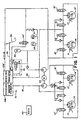
- the brake system 10 as shown in Figure 1 includes a hydraulic brake booster or regulator 12 connected to a first set of wheel brakes 14,14' by a first conduit 16 and to a second set of wheel brakes 18,18' by a second conduit 20.
- the hydraulic brake booster 12 receives pressurized supply fluid from a source that may include an accumulator 22 and a motor pump 24.
- the hydraulic brake booster 12 is selectively activated by either a manual force applied to an input arrangement 49 that includes brake pedal 28, input rod 30 and lever arrangement 50, to effect a first brake application or by a hydraulic force developed as a function of a signal received from an electronic control member (ECU) 40 to activate a solenoid valve 34 connected to with the pressurized supply fluid and effect a second brake application.
- ECU electronice control member
- the brake system 10 also includes a build solenoid valve 15, a decay solenoid valve 15' and a wheel speed sensor 17 for each wheel in the first set of wheel brakes 14,14' and in the second set of wheel brakes 18,18' to provide the electronic control unit (ECU) 40 with an input signals to provide information or data relating to a current functional operational of the vehicle.
- the ECU 40 also receives and evaluates other inputs and data relating to the vehicle including but not limited to: the operation of the motor pump; the pressure of the pressurized supply fluid; dynamic forces experienced by the vehicle; accumulator fluid supply pressure, the level of fluid in a reservoir and etc. all inputs which relate to the operation of the vehicle and may effect a brake application.
- the hydraulic brake booster 12 responds to an operator input force (manual input) applied to brake pedal 28 to directly communicate regulated pressurized supply fluid to wheel brakes 18,18' and indirectly by way of the development of operational pressurized fluid by a power piston 118 provided to wheel brakes 14,14' to effect a brake application.
- the operation of the brake booster On termination of the operator input force to brake pedal 28, the operation of the brake booster is returned to a rest state as illustrated in Figure 2.
- the ECU 40 is programmed to transmit an operating signal that activates a solenoid 34 to allow the flow of pressurized supply fluid from the accumulator 22 and hydraulically activate the hydraulic brake booster 12.
- supply regulated pressurized fluid When hydraulically activated, supply regulated pressurized fluid is directly communicated to wheel brakes 18,18' and depending on a current situation, the supply pressurized fluid may be selectively communicated to develop operational pressurized fluid by the power piston 118 which is supplied to wheel brakes 14,14' and effect a brake application that is designed to attenuate an undesirable operating condition which could effect the safe operation of the vehicle.
- the hydraulic brake booster 12 as shown in detail in Figure 2 includes a first housing 100 that is joined to a second housing 200.
- the first housing has a first bore 102 that is separated from a second bore 104.
- the second housing 200 engages the first housing 100 to define a cavity 202 which is located adjacent the first bore 102 and second bore 104.
- Cavity 202 is designed to be connected to reservoir 108 and as such is maintained at essentially a same low pressure as reservoir 108.
- the first bore 102 of housing 100 is connected to the first set of wheel brakes 14,14' by way of conduit 16 which is connected through to an operational or output port 110 in end plug member 116, to cavity 202 and replenishing supply fluid available in fluid reservoir 108 by way of a flow path from compensation port 106 and to the second bore 104 by a supply port 114 in passage 128 for receiving metered pressurized fluid from an operational chamber 190.
- Power piston 118 is located in the first bore 102 and with end wall 101 defines an actuation chamber 125 therein.
- a first annular projection 117 on power piston 118 extends through end wall 101 into the cavity 202 while a second annular projection 117' extends into a bore 112 formed in end plug member 116.
- the second annular projection 117' carries a seal 119 which in a rest position is located adjacent compensation port 106 to allow for free communication of fluid available in reservoir 108 to be communicated to conduit 16.
- a return spring 122 located between end plug member 116 and the second annular projection 117', urges the power piston 118 toward a rest position defined by end wall 101.
- a first seal 124 carried by power piston 118 engages bore 102 and a second seal 124' retained in end wall 101 is designed seal actuation chamber 125 from cavity 202 which has a fluid pressure substantially equal to the fluid pressure in reservoir 108.
- the first annular projection 117 has a bore 128' that extends from end 118' to receives a piston 140 attached to the end extension 30' of push rod 30 of the input arrangement 49. Bore 128' is connected with actuation chamber 125 by a cross bore 114 and receives piston 140 to define a reaction chamber 142 within the power piston 118.
- the second bore 104 is connected to receive pressurized supply fluid from the accumulator 22 by way of port 21' connected to supply conduit 21.
- the second bore 104 has several steps therein to receive and retains a control valve arrangement 170. Regulated pressurized supply fluid from the second bore 104 is simultaneously communicated to the first bore 102 for developing an operational fluid pressure by the power piston 118 which is communicated to the first set of wheel brakes 14,14' and directly to the second passage 130 in housing 100 for supplying the second set of wheel brakes 18,18' to effect a brake application.
- the control valve arrangement 170 is located in the second bore 104 and defined by a cylindrical member 172 which is fixed in the second bore 104, a movable closure arrangement 180, a movable plunger 188; a return or closure spring 185; a sleeve or collar 248; a return spring 194; and a bearing 196.
- the cylindrical member 172 is held in the second bore 104 by the second housing 200 to define a supply chamber 174 within the second bore 104.
- the supply chamber 174 is connected to accumulator 22 by way of port 21' and may freely receive pressurized supply fluid available from either accumulator 22 or motor pump 24.
- the cylindrical member 172 has a wall 171 with a tapered opening 171' which is surrounded by a seat 173, an axial bore 178 and a cross bore 176, 176' which connects axial bore 178 to the actuation chamber 125 by way of the first passage 128 and to the second set of wheel brakes 18,18' by way of the second passage 130.
- the closure arrangement 180 includes a stem 180' designed to axially slide in bore 104, a head 181 formed on the end of stem 180' which retains a ball 182 and a return spring 184.
- the return or closure spring 184 acts on head 181 to urge ball 182 toward wall 171 of cylindrical member 172 and into engagement with seat 173 to seal the supply chamber 174 and retain the pressurized supply fluid therein.
- Bore 104 is also connected to the second passage 130 by a passage 175 to provide a flow path through which fluid available in the second passage 130 is communicated to act on stem 180' and assist in balancing the fluid pressure across the ball 182.
- the plunger 188 is defined by a cylindrical body 188' that has a peripheral surface 186 which engages bore 178 in the cylindrical member 172 to define an operational chamber 190 within the second bore 104.
- a hollow stem 192 connected to the cylindrical body 188' extends into the operational chamber 190 and connects the operational chamber 190 with a relief chamber formed by cavity 202 between the first 100 and second 200 housings.
- Cylindrical body 188' also has a bore 94 formed therein which is connected to the operational chamber 190 by a third passage 132 and a peripheral surface 186 thereon has a shoulder 186' that separates a diameter 186" from a diameter 186"'.
- a port 192' in diameter 186" forms an exit for a passage 191 from the hollow stem 192 through which the operational chamber 190 is connected to the cavity or relief chamber 202 while diameter 186''' provides a surface for receiving sleeve or collar 248 through which input forces are received from the lever arrangement 50.
- a bearing 196 which surrounds diameter 186''' of cylindrical body 188 is sealingly located in an indentation 206 formed in a second piston 208.
- the second piston 208 being located in a bore 210 of the second housing 200.
- the sealing engagement of bearing 196 with indentation 206 in the second piston 208 defines a reaction chamber 195 within the bore 94 of plunger 186.
- the second piston 208 also carries a seal 209 that engages bore 210 to define a secondary actuation chamber 212 in the second housing 200.
- the secondary actuation chamber 212 is connected to conduit 23 and selectively receives pressurized supply fluid from a source (either accumulator 22 or motor pump 24) on activation of solenoid 34 by an input signal from the ECU 40.
- the second piston 208 has a projection 208' that extends therefrom and engages bore 94 of plunger 188 to assist in aligning the control valve arrangement 170 in the second bore 104.
- the lever arrangement 50 while functionally similar to levers disclosed in the prior art is distinguished therefrom by a base 250 having an annular collar 252 which is located on the peripheral surface of the first annular projection 117 by a snap ring 254 to define an extension of the power piston 118.
- the lever arrangement 50 as additionally illustrated in Figure 7, includes first and second arms 256, 256' and is of a type more fully disclosed in the prior art including U. S.
- Patent 4,625,515 wherein arm 256 has a first end 258 and arm 256' has a first end 258' fixed to the base 250 by a pivot pin 260 and a second end 262 with a nib or button 264 that is located in groove 247 of sleeve or collar 248 carried on peripheral surface 186''' of plunger 188.
- a bracket 52 carried by push rod extension 30' has a base 54 which is urged into engagement with piston 140 by a spring 56.
- Parallel side walls 58,58' that extend away from base 54 each have a vertical slot 266 (only one of which is shown) for receiving a corresponding nib 31 located on arm 256,256' to form a connection with input push rod extension 30'.
- the functional operation of the sleeve or collar 248 with the lever arrangement 50 defines over the prior lever arrangements to permit independent movement of the power piston 118 and control valve arrangement 170 such that movement of the input push rod 30 is coordinated with the movement of plunger 188 and balancing of the position of the plunger 188 with respect to seat 173 on wall 171 to meter flow into the operational chamber 190 is not adversely effect the development of the operational fluid pressure by the power piston 118.
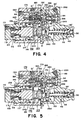
- the hydraulic booster 12 for the brake system 10 of Figure 1 is shown in Figure 2 in a rest position with the power piston 118 and control valve arrangement 170 respectively urged toward stops by return springs 122, 184.
- pressurized supply fluid available in accumulator 22 is communicated to supply chamber 174 by way of inlet port 21' and conduit 21.
- base 250 of the lever arrangement 50 attached to annular projection 117 of power piston 118 engages housing 200 such that bore 112 therein is connected to cavity 202 and reservoir 108 by compensation port 106.
- actuation chamber 125 is also connected to cavity or relief chamber 202 by way of passage 128, cross bore 176,176', operational chamber 190, stem 192, passage 191 and port 192'.
- the fluid pressure of the fluid in reservoir 108 and relief chamber 202 is the same and as illustrated are connected to each other for replenishing purposes, however, structure is envisioned which could provided independence and separate operation of each system when the fluid level in the reservoir 108 drops to a predetermined level.
- the fluid pressure across the power piston 118 is also the same and as a result return spring 122 maintains the input arrangement 49 in a rest position, as illustrated in Figure 2.
- control valve arrangement 170 is also balanced as passages 175 and 130 are connected to the operational chamber 190 and communicate equal fluid pressure across the closure arrangement 180 such that spring 184 urges ball 182 into engagement with seat 173 to seal chamber 174.
- return spring 185 acts on cylindrical body 188' of plunger 188 to urge the plunger 188 toward the second piston 208 and maintain the lever arrangement 50 in a substantially vertical position.
- an input force is applied to brake pedal 28.
- the input force is transmitted by input push rod 30 and extension 30' to move piston 140 within bore 141 and the power piston 118 in bore 102. Movement of power piston 118 within bore 102 closes bore 112 as seal 119 on annular projection 117' moves past compensation port 106.
- the input force as applied to push rod 30 is transmitted into lever arms 256 from bracket 52 by way of pins 31 and since end 258 is fixed on pin 260, end 262 pivots to exert a corresponding force on plunger 188 by way of pins 264 acting through collar 248.
- the regulated pressurized supply fluid is simultaneously communicated to the operational chamber 125 to initiate braking of the first set of wheel brakes 14,14' by way of operational fluid pressurized by movement of the power piston 118 and to passage 130 to directly initiate braking of the second set of wheel brakes 18,18'.
- the regulated pressurized supply fluid presented to chamber 125 acts on power piston 118 and after overcoming return spring 122 moves the power piston 118 and annular projection 117' toward the end cap 116 to pressurize operational fluid in bore 112.
- This pressurized operational fluid is communicated to the first set of wheel brakes 14,14' to effect a brake application therein and is coordinated with the regulated pressurized supply fluid which is directly communicated to the second set of wheel brakes 18,18' to effect a brake application therein.
- the regulated pressurized supply fluid is communicated to reaction chamber 142 and acts on piston 140 to provide push rod 30 of the input arrangement 49 with a feed back indicative of the regulated pressurized supply fluid being supplied to the wheel brakes to effect a brake application.
- a balance effect is achieved in the control valve arrangement 170, as regulated pressurized supply fluid from operational chamber 190 is communicated through passage 132 into bore 94 and equally acts across plunger 188 and bearing 196 to mitigate any effect the pressurized supply fluid may have on the input force acting on plunger 188 through sleeve 248.
- control valve arrangement 170 functions in a smooth and substantially frictionless manner as the closure arrangement 180 and plunger 188 are arranged such the pressurized supply fluid and regulated pressurized supply fluid do not directly act on seals associated with the control valve arrangement 170.
- the secondary actuation feature of the hydraulic booster 12 for the brake system 10 is under the control of the ECU 40.
- the ECU 40 is responsive to situations that may adversely effect a desired operation of the vehicle, and in particular wheel skid, wheel spin or sway of the vehicle. In such situations, sensors such the wheel speed sensors 17 provide the ECU 40 with input signals that are evaluated to determine if a brake application would be justified in order to achieve a safer or more effective operation of the vehicle.
- an operational signal is sent to activate solenoid 34 which allows pressurized supply fluid to flow from accumulator 22 (a second and independent accumulator may be utilized for some applications) into secondary actuation chamber 212 by way of conduit 23 and inlet port 23' in the second housing 200.
- the pressurized supply fluid in secondary actuation chamber 212 acts on and moves the second piston 208 in bore 210 to provide a secondary actuation force that acts on end 187 of plunger 188 and after overcoming return spring 185 moves stem 192 into engagement with ball 182.
- the lever arrangement 50 remains stationary as surface 186''' on plunger 188 slides in sleeve 248 and as a result brake pedal 28 remains stationary after an initial drop corresponding to movement of power piston 118 sufficiently past compensatory port 106 to close bore 102.
- stem 192 engages ball 182
- communication is terminated between the operational chamber 190 and relief chamber 202 and with further movement of plunger 188 by the second piston 208, ball 182 is now moved off seat 173 to allow regulated pressurized supply fluid to flow from supply chamber 174 into the operational chamber 190 in a manner as shown in Figure 6.
- the regulated pressurized supply fluid presented to operational chamber 190 is immediately communicated to the second set of wheel brakes 18,18' by way of passage 130 to effect a brake application.
- the regulated pressurized supply fluid communicated to the operational chamber 190 through the movement of plunger 188 by the secondary actuation piston 208 is also supplied to actuation chamber 125 and moves the power piston 118 in bore 102 such that seal 119 carried by projection 117' moves past compensation port 106 to pressurize fluid in bore 112.
- the pressurized supply fluid continues to act on the power piston 118 and move the projection 117' in bore 112 to pressurize operational fluid which is supplied to the first set of wheel brakes 14,14' to effect a corresponding brake application of a wheel brake by the selective actuation of the build solenoid valve 15 or the hold solenoid valve 15' to correct the situation.
- a hydraulic lock is created in bore 112 by closing the build solenoid valves 15 for each of the first set of wheel brakes 14,14' such that power piston 118 remains in a stationary position within bore 102 and braking is limited to the wheel brakes in the second set of wheel brakes 18,18' which are supplied pressurized supply fluid by conduit 20 connected to passage 130.
- the ECU 40 will selectively activate an individual build solenoid valve 15 or hold solenoid valve 15' associated with each the wheel brakes 18,18' to correct the situation.
- a relief solenoid 34' opens to allow the pressurized supply fluid in chamber 212 to flow to reservoir 108' for the motor pump 24.
- return spring 184 moves ball 182 on stem 180' into engagement with seat 173 to seal the supply chamber 174 and return spring 185 returns plunger 188 and the second piston 200 to a rest position, as best shown in Figure 2, such that bore 112 and the operational chamber 190 in the first housing 100 are connected to cavity 202 for replenishing any fluid need to maintain the system.
Landscapes
- Engineering & Computer Science (AREA)
- Transportation (AREA)
- Mechanical Engineering (AREA)
- Physics & Mathematics (AREA)
- Fluid Mechanics (AREA)
- Regulating Braking Force (AREA)
- Braking Systems And Boosters (AREA)
Abstract
Claims (8)
- Servofrein hydraulique (12) destiné à être utilisé dans un système de freins (10), comportant un premier boítier (100) muni d'un premier alésage (102) séparé d'un second alésage (104), le premier alésage (102) contenant un piston de puissance (118) et le second alésage (104) contenant une soupape de commande (170), un élément d'entrée (49) étant connecté au piston de puissance (118) et lié à la soupape de commande (170) par un dispositif de levier (50), le second alésage (104) étant connecté à une source de fluide d'alimentation sous pression et le premier alésage (102) étant connecté à un premier ensemble de freins de roues (14, 14') d'un véhicule, le dispositif de levier (50) fournissant à la soupape de commande (170) une force d'entrée répondant à une force de freinage appliquée à l'élément d'entrée (49) pour mesurer le fluide d'alimentation sous pression et créer un fluide d'alimentation comprimé régulé qui est transmis par un premier passage (128) pour agir sur le piston de puissance (118) et déplacer celui-ci de manière à développer un fluide opérationnel qui est mis en communication avec le premier ensemble de freins de roues (14, 14'), et par un second passage (130) pour arriver directement à un second ensemble de freins de roues de manière à effectuer une application de freinage, ce servofrein hydraulique (12) étant
caractérisé par
un second boítier (200) qui maintient la soupape de commande (170) dans le second alésage (104) tout en enfermant la soupape de commande (170), le dispositif de levier (50) et une saillie (117) partant du piston de puissance (118), pour définir une chambre de décharge (202) présentant une pression de fluide permanente inférieure à celle de la source de fluide d'alimentation sous pression, le premier alésage (102) et le second alésage (104) étant connectés à la chambre de décharge (202) en l'absence d'application d'une force d'entrée à la soupape de commande (170). - Servofrein hydraulique (12) selon la revendication 1,
dans lequel
la soupape de commande (170) est caractérisée par un élément cylindrique (172) fixé dans le second alésage (104) par le second boítier (200) pour définir une chambre d'alimentation (174) à l'intérieur du second alésage (104), un premier élément de tige (180') placé dans le second alésage (104) et poussé en contact avec un siège (173) formé sur l'élément cylindrique (172) pour fermer la chambre d'alimentation (174), un plongeur (188) placé dans un alésage central à l'intérieur de l'élément cylindrique (172) pour définir une chambre opérationnelle (190) à l'intérieur du second alésage (104), et comportant sur celui-ci une seconde tige (192) qui pénètre dans la chambre opérationnelle (190), cette chambre opérationnelle (190) étant connectée à la chambre de décharge (202) par la seconde tige (192), le plongeur (188) répondant à une force d'entrée provenant du dispositif de levier (50) en se déplaçant initialement à l'intérieur de la chambre opérationnelle (190) pour amener la seconde tige (192) en contact avec la première tige (180') afin de couper la communication entre la chambre opérationnelle (190) et la chambre de décharge (202), puis en écartant la première tige (180') du siège (173) pour mesurer le fluide d'alimentation qui passe de la chambre d'alimentation (174) dans la chambre opérationnelle (190) sous forme de fluide d'alimentation comprimé régulé. - Servofrein hydraulique (12) selon la revendication 2,
dans lequel
le second boítier (200) est en outre caractérisé par un troisième alésage (210) qui reçoit un second piston (208) pour définir une chambre d'actionnement secondaire (212), ce second piston (208) étant connecté au plongeur (188) et répondant au fluide comprimé secondaire fourni à la chambre d'actionnement secondaire (212) pour déplacer initialement le plongeur (188) dans la chambre opérationnelle (190) de manière à amener la seconde tige (192) en contact avec la première tige (180') pour couper la communication entre la chambre opérationnelle (190) et la chambre de décharge (202), puis pour écarter la première tige (180') du siège (173) de manière à mesurer le fluide d'alimentation passant de la chambre d'alimentation (174) dans la chambre opérationnelle (190), et à fournir au second ensemble de freins de roues (18, 18') du fluide d'alimentation comprimé régulé pour effectuer une application de freinage. - Servofrein hydraulique (12) selon la revendication 3,
caractérisé en outre en ce que
le fluide d'alimentation comprimé régulé déplace le premier piston (118) pour fermer la communication entre le premier alésage (102) et la chambre de décharge (202) lorsque le fluide comprimé secondaire est fourni à la chambre d'actionnement secondaire (212) et à des moyens destinés à empêcher le mouvement du premier piston (118) après fermeture de la communication avec la chambre d'échappement (202) de manière à maintenir l'élément d'entrée (49) dans une position fixe. - Servofrein hydraulique (12) selon la revendication 4,
dans lequel
les moyens pour empêcher le mouvement du premier piston (118) sont caractérisés par une électrovanne (15, 15') qui ferme la communication avec le premier ensemble de freins de roues (14, 14') pour créer un verrouillage hydraulique dans le premier alésage (102). - Servofrein hydraulique (12) selon la revendication 5,
dans lequel
la chambre opérationnelle (190) et une chambre de réaction (195) sont caractérisées en ce qu'elles sont formées entre un plongeur (180) et le second piston (208) pour équilibrer les forces de part et d'autre du plongeur (188) lorsqu'une entrée est reçue du dispositif de levier (50). - Servofrein hydraulique (12) selon la revendication 6,
dans lequel
la soupape de commande (170) est en outre caractérisée par un premier ressort (185) placé dans la chambre opérationnelle (190) pour assister le déplacement du plongeur (188) vers une position de repos lorsque la communication est établie entre le second passage (130) et la chambre de décharge (202), ainsi que par un second ressort (194) placé entre un manchon (264) et le second piston (208) pour pousser le second piston (208) vers la seconde chambre d'actionnement (212) de manière à définir une position de repos pour le second piston (208). - Servofrein hydraulique (12) selon la revendication 3,
caractérisé en outre en ce que
le fluide d'alimentation comprimé régulé déplace le premier piston (118) pour fermer la communication entre le premier alésage (102) et la chambre de décharge (202) lorsque le fluide comprimé secondaire est fourni à la chambre d'actionnement secondaire (212) pour développer le fluide opérationnel qui est mis en communication avec un premier ensemble de freins de roues (14, 14') pendant une application de freinage secondaire.
Applications Claiming Priority (3)
| Application Number | Priority Date | Filing Date | Title |
|---|---|---|---|
| US894106 | 2001-06-28 | ||
| US09/894,106 US6561596B2 (en) | 2001-06-28 | 2001-06-28 | Brake booster |
| PCT/US2002/014451 WO2003002393A1 (fr) | 2001-06-28 | 2002-05-07 | Servofrein |
Publications (2)
| Publication Number | Publication Date |
|---|---|
| EP1404555A1 EP1404555A1 (fr) | 2004-04-07 |
| EP1404555B1 true EP1404555B1 (fr) | 2005-06-08 |
Family
ID=25402614
Family Applications (1)
| Application Number | Title | Priority Date | Filing Date |
|---|---|---|---|
| EP02731709A Expired - Lifetime EP1404555B1 (fr) | 2001-06-28 | 2002-05-07 | Servofrein |
Country Status (6)
| Country | Link |
|---|---|
| US (1) | US6561596B2 (fr) |
| EP (1) | EP1404555B1 (fr) |
| JP (1) | JP2004521825A (fr) |
| DE (1) | DE60204570T2 (fr) |
| ES (1) | ES2242025T3 (fr) |
| WO (1) | WO2003002393A1 (fr) |
Families Citing this family (4)
| Publication number | Priority date | Publication date | Assignee | Title |
|---|---|---|---|---|
| US6732518B1 (en) * | 2002-12-02 | 2004-05-11 | Robert Bosch Corporation | Hydraulic brake booster |
| US6981438B1 (en) | 2004-01-29 | 2006-01-03 | Robert Bosch Corporation | Hydraulic brake booster |
| US6990812B2 (en) * | 2004-04-29 | 2006-01-31 | Robert Bosch Gmbh | Control valve for a hydraulic brake booster |
| DE102023209910A1 (de) | 2023-10-10 | 2025-04-10 | Robert Bosch Gesellschaft mit beschränkter Haftung | Rechnervorrichtung und Verfahren zum Ermitteln einer auf zumindest ein Getriebe einer motorisierten Bremsdruckaufbauvorrichtung eines Fahrzeugs extern einwirkenden Kraft |
Family Cites Families (23)
| Publication number | Priority date | Publication date | Assignee | Title |
|---|---|---|---|---|
| JPS5813379B2 (ja) * | 1974-10-31 | 1983-03-14 | アイシンセイキ カブシキガイシヤ | ハイドロリツクブ−スタ |
| FR2332445A1 (fr) * | 1975-11-21 | 1977-06-17 | Dba | Amplificateur hydraulique |
| US4281585A (en) | 1978-03-13 | 1981-08-04 | The Bendix Corporation | Hydraulic brake booster and valve member |
| US4441319A (en) | 1982-09-01 | 1984-04-10 | The Bendix Corporation | Brake booster |
| DE3240680A1 (de) * | 1982-11-04 | 1984-05-10 | Robert Bosch Gmbh, 7000 Stuttgart | Hauptbremszylinder |
| DE3320822A1 (de) * | 1983-06-09 | 1984-12-13 | Alfred Teves Gmbh, 6000 Frankfurt | Hydraulische bremsanlage |
| FR2559724B1 (fr) * | 1984-02-22 | 1990-06-29 | Dba | Dispositif generateur de pression de freinage pour installation de freinage a double circuit |
| US4539892A (en) * | 1984-03-12 | 1985-09-10 | Allied Corporation | Hydraulic brake booster |
| DE3420687A1 (de) * | 1984-06-02 | 1985-12-05 | Robert Bosch Gmbh, 7000 Stuttgart | Bremsdrucksteuerventil insbesondere fuer einen bremskraftverstaerker |
| DE3420689A1 (de) * | 1984-06-02 | 1985-12-05 | Robert Bosch Gmbh, 7000 Stuttgart | Bremskraftverstaerker |
| US4625515A (en) | 1984-09-20 | 1986-12-02 | Allied Corporation | Brake booster |
| DE3527317A1 (de) * | 1985-07-31 | 1987-02-05 | Teves Gmbh Alfred | Hydraulische bremsanlage mit schlupfregelung, insbesondere fuer kraftfahrzeuge |
| DE3538763A1 (de) * | 1985-10-31 | 1987-05-07 | Teves Gmbh Alfred | Fremdenergiegespeiste bremsschlupfregelanlage eines hydraulischen fahrzeugbremssystems |
| DE3605997A1 (de) * | 1986-02-25 | 1987-08-27 | Teves Gmbh Alfred | Blockiergeschuetzte hydraulische bremsanlage |
| DE3612944A1 (de) * | 1986-04-17 | 1987-10-22 | Teves Gmbh Alfred | Hydraulikanlage, insbesondere fuer kraftfahrzeuge |
| DE3700461A1 (de) * | 1987-01-09 | 1988-07-21 | Teves Gmbh Alfred | Hydraulische bremsanlage fuer kraftfahrzeuge |
| JP2581065B2 (ja) * | 1987-03-31 | 1997-02-12 | アイシン精機株式会社 | 液圧ブレ−キ装置 |
| JPH0825440B2 (ja) * | 1988-07-30 | 1996-03-13 | アイシン精機株式会社 | 液圧ブレーキ装置 |
| JPH0717612Y2 (ja) * | 1989-02-04 | 1995-04-26 | アイシン精機株式会社 | 液圧ブレーキ装置 |
| JPH0357760A (ja) * | 1989-07-25 | 1991-03-13 | Toyota Motor Corp | 液圧ブースタ装置 |
| JPH03118267A (ja) * | 1989-09-30 | 1991-05-20 | Aisin Seiki Co Ltd | 液圧ブレーキ装置 |
| JPH0687418A (ja) * | 1992-09-04 | 1994-03-29 | Toyota Motor Corp | 液圧ブレーキ装置 |
| US6203119B1 (en) | 1999-08-02 | 2001-03-20 | Robert Bosch Corporation | Control apparatus for a brake system |
-
2001
- 2001-06-28 US US09/894,106 patent/US6561596B2/en not_active Expired - Lifetime
-
2002
- 2002-05-07 ES ES02731709T patent/ES2242025T3/es not_active Expired - Lifetime
- 2002-05-07 DE DE60204570T patent/DE60204570T2/de not_active Expired - Fee Related
- 2002-05-07 WO PCT/US2002/014451 patent/WO2003002393A1/fr not_active Ceased
- 2002-05-07 JP JP2003508591A patent/JP2004521825A/ja active Pending
- 2002-05-07 EP EP02731709A patent/EP1404555B1/fr not_active Expired - Lifetime
Also Published As
| Publication number | Publication date |
|---|---|
| EP1404555A1 (fr) | 2004-04-07 |
| DE60204570T2 (de) | 2006-03-16 |
| DE60204570D1 (de) | 2005-07-14 |
| WO2003002393B1 (fr) | 2003-03-06 |
| WO2003002393A1 (fr) | 2003-01-09 |
| JP2004521825A (ja) | 2004-07-22 |
| ES2242025T3 (es) | 2005-11-01 |
| US6561596B2 (en) | 2003-05-13 |
| US20030067218A1 (en) | 2003-04-10 |
Similar Documents
| Publication | Publication Date | Title |
|---|---|---|
| US4598955A (en) | Slip control system master cylinder with piston sleeve | |
| US4072011A (en) | Hydraulic brake booster | |
| US6343469B1 (en) | Hydraulic system regulator for a brake and steering system | |
| US4196592A (en) | Hydraulic brake booster | |
| EP1404555B1 (fr) | Servofrein | |
| US8366205B1 (en) | Blended hydraulic brake booster | |
| US5316378A (en) | Brake fluid pressure control apparatus | |
| JPH01273761A (ja) | 液圧ブレーキシステム用タンデム型マスターシリンダ | |
| US6203119B1 (en) | Control apparatus for a brake system | |
| JPH04131566U (ja) | 液圧ブレーキシステム | |
| EP1569833B1 (fr) | Servofrein hydraulique | |
| US6280002B1 (en) | Hydraulic braking system | |
| US6591611B2 (en) | Hydraulic brake booster | |
| US6990812B2 (en) | Control valve for a hydraulic brake booster | |
| US4858737A (en) | Hydraulic braking device for automobile vehicle | |
| US6981438B1 (en) | Hydraulic brake booster | |
| US6038857A (en) | Control apparatus for a brake booster | |
| US6668552B1 (en) | Hydraulic brake booster | |
| US5052182A (en) | Hydraulic brake booster system with check valve in brake fluid reservoir line | |
| US6050089A (en) | Remotely located brake booster | |
| JPH0631257Y2 (ja) | 圧力制御弁 | |
| JPS6243347A (ja) | アンチスキツド制御装置 | |
| JPH01223061A (ja) | 車両ブレーキ装置 | |
| JPS5855022B2 (ja) | 流体ブレ−キブ−スタ | |
| JPH11245797A (ja) | ブレーキ液圧制御装置 |
Legal Events
| Date | Code | Title | Description |
|---|---|---|---|
| PUAI | Public reference made under article 153(3) epc to a published international application that has entered the european phase |
Free format text: ORIGINAL CODE: 0009012 |
|
| 17P | Request for examination filed |
Effective date: 20040128 |
|
| AK | Designated contracting states |
Kind code of ref document: A1 Designated state(s): AT BE CH CY DE DK ES FI FR GB GR IE IT LI LU MC NL PT SE TR |
|
| 17Q | First examination report despatched |
Effective date: 20040429 |
|
| GRAP | Despatch of communication of intention to grant a patent |
Free format text: ORIGINAL CODE: EPIDOSNIGR1 |
|
| GRAS | Grant fee paid |
Free format text: ORIGINAL CODE: EPIDOSNIGR3 |
|
| GRAA | (expected) grant |
Free format text: ORIGINAL CODE: 0009210 |
|
| AK | Designated contracting states |
Kind code of ref document: B1 Designated state(s): DE ES FR GB IT |
|
| REG | Reference to a national code |
Ref country code: GB Ref legal event code: FG4D |
|
| REF | Corresponds to: |
Ref document number: 60204570 Country of ref document: DE Date of ref document: 20050714 Kind code of ref document: P |
|
| REG | Reference to a national code |
Ref country code: ES Ref legal event code: FG2A Ref document number: 2242025 Country of ref document: ES Kind code of ref document: T3 |
|
| ET | Fr: translation filed | ||
| PLBE | No opposition filed within time limit |
Free format text: ORIGINAL CODE: 0009261 |
|
| STAA | Information on the status of an ep patent application or granted ep patent |
Free format text: STATUS: NO OPPOSITION FILED WITHIN TIME LIMIT |
|
| 26N | No opposition filed |
Effective date: 20060309 |
|
| PGFP | Annual fee paid to national office [announced via postgrant information from national office to epo] |
Ref country code: ES Payment date: 20080523 Year of fee payment: 7 |
|
| PGFP | Annual fee paid to national office [announced via postgrant information from national office to epo] |
Ref country code: IT Payment date: 20080526 Year of fee payment: 7 |
|
| PGFP | Annual fee paid to national office [announced via postgrant information from national office to epo] |
Ref country code: DE Payment date: 20080728 Year of fee payment: 7 |
|
| PGFP | Annual fee paid to national office [announced via postgrant information from national office to epo] |
Ref country code: GB Payment date: 20080522 Year of fee payment: 7 |
|
| GBPC | Gb: european patent ceased through non-payment of renewal fee |
Effective date: 20090507 |
|
| REG | Reference to a national code |
Ref country code: FR Ref legal event code: ST Effective date: 20100129 |
|
| PG25 | Lapsed in a contracting state [announced via postgrant information from national office to epo] |
Ref country code: FR Free format text: LAPSE BECAUSE OF NON-PAYMENT OF DUE FEES Effective date: 20090602 |
|
| PGFP | Annual fee paid to national office [announced via postgrant information from national office to epo] |
Ref country code: FR Payment date: 20080519 Year of fee payment: 7 |
|
| PG25 | Lapsed in a contracting state [announced via postgrant information from national office to epo] |
Ref country code: GB Free format text: LAPSE BECAUSE OF NON-PAYMENT OF DUE FEES Effective date: 20090507 |
|
| PG25 | Lapsed in a contracting state [announced via postgrant information from national office to epo] |
Ref country code: DE Free format text: LAPSE BECAUSE OF NON-PAYMENT OF DUE FEES Effective date: 20091201 |
|
| REG | Reference to a national code |
Ref country code: ES Ref legal event code: FD2A Effective date: 20090508 |
|
| PG25 | Lapsed in a contracting state [announced via postgrant information from national office to epo] |
Ref country code: ES Free format text: LAPSE BECAUSE OF NON-PAYMENT OF DUE FEES Effective date: 20090508 |
|
| PG25 | Lapsed in a contracting state [announced via postgrant information from national office to epo] |
Ref country code: IT Free format text: LAPSE BECAUSE OF NON-PAYMENT OF DUE FEES Effective date: 20090507 |