EP1447720A2 - Tonerbehälter - Google Patents
Tonerbehälter Download PDFInfo
- Publication number
- EP1447720A2 EP1447720A2 EP04010327A EP04010327A EP1447720A2 EP 1447720 A2 EP1447720 A2 EP 1447720A2 EP 04010327 A EP04010327 A EP 04010327A EP 04010327 A EP04010327 A EP 04010327A EP 1447720 A2 EP1447720 A2 EP 1447720A2
- Authority
- EP
- European Patent Office
- Prior art keywords
- toner
- toner container
- container
- air
- tubular body
- Prior art date
- Legal status (The legal status is an assumption and is not a legal conclusion. Google has not performed a legal analysis and makes no representation as to the accuracy of the status listed.)
- Granted
Links
Images










Classifications
-
- G—PHYSICS
- G03—PHOTOGRAPHY; CINEMATOGRAPHY; ANALOGOUS TECHNIQUES USING WAVES OTHER THAN OPTICAL WAVES; ELECTROGRAPHY; HOLOGRAPHY
- G03G—ELECTROGRAPHY; ELECTROPHOTOGRAPHY; MAGNETOGRAPHY
- G03G15/00—Apparatus for electrographic processes using a charge pattern
- G03G15/06—Apparatus for electrographic processes using a charge pattern for developing
- G03G15/08—Apparatus for electrographic processes using a charge pattern for developing using a solid developer, e.g. powder developer
- G03G15/0822—Arrangements for preparing, mixing, supplying or dispensing developer
- G03G15/0877—Arrangements for metering and dispensing developer from a developer cartridge into the development unit
- G03G15/0879—Arrangements for metering and dispensing developer from a developer cartridge into the development unit for dispensing developer from a developer cartridge not directly attached to the development unit
-
- G—PHYSICS
- G03—PHOTOGRAPHY; CINEMATOGRAPHY; ANALOGOUS TECHNIQUES USING WAVES OTHER THAN OPTICAL WAVES; ELECTROGRAPHY; HOLOGRAPHY
- G03G—ELECTROGRAPHY; ELECTROPHOTOGRAPHY; MAGNETOGRAPHY
- G03G15/00—Apparatus for electrographic processes using a charge pattern
- G03G15/06—Apparatus for electrographic processes using a charge pattern for developing
- G03G15/08—Apparatus for electrographic processes using a charge pattern for developing using a solid developer, e.g. powder developer
-
- G—PHYSICS
- G03—PHOTOGRAPHY; CINEMATOGRAPHY; ANALOGOUS TECHNIQUES USING WAVES OTHER THAN OPTICAL WAVES; ELECTROGRAPHY; HOLOGRAPHY
- G03G—ELECTROGRAPHY; ELECTROPHOTOGRAPHY; MAGNETOGRAPHY
- G03G15/00—Apparatus for electrographic processes using a charge pattern
- G03G15/06—Apparatus for electrographic processes using a charge pattern for developing
- G03G15/08—Apparatus for electrographic processes using a charge pattern for developing using a solid developer, e.g. powder developer
- G03G15/0822—Arrangements for preparing, mixing, supplying or dispensing developer
- G03G15/0848—Arrangements for testing or measuring developer properties or quality, e.g. charge, size, flowability
- G03G15/0849—Detection or control means for the developer concentration
- G03G15/0855—Detection or control means for the developer concentration the concentration being measured by optical means
-
- G—PHYSICS
- G03—PHOTOGRAPHY; CINEMATOGRAPHY; ANALOGOUS TECHNIQUES USING WAVES OTHER THAN OPTICAL WAVES; ELECTROGRAPHY; HOLOGRAPHY
- G03G—ELECTROGRAPHY; ELECTROPHOTOGRAPHY; MAGNETOGRAPHY
- G03G15/00—Apparatus for electrographic processes using a charge pattern
- G03G15/06—Apparatus for electrographic processes using a charge pattern for developing
- G03G15/08—Apparatus for electrographic processes using a charge pattern for developing using a solid developer, e.g. powder developer
- G03G15/0822—Arrangements for preparing, mixing, supplying or dispensing developer
- G03G15/0865—Arrangements for supplying new developer
-
- G—PHYSICS
- G03—PHOTOGRAPHY; CINEMATOGRAPHY; ANALOGOUS TECHNIQUES USING WAVES OTHER THAN OPTICAL WAVES; ELECTROGRAPHY; HOLOGRAPHY
- G03G—ELECTROGRAPHY; ELECTROPHOTOGRAPHY; MAGNETOGRAPHY
- G03G15/00—Apparatus for electrographic processes using a charge pattern
- G03G15/06—Apparatus for electrographic processes using a charge pattern for developing
- G03G15/08—Apparatus for electrographic processes using a charge pattern for developing using a solid developer, e.g. powder developer
- G03G15/0822—Arrangements for preparing, mixing, supplying or dispensing developer
- G03G15/0865—Arrangements for supplying new developer
- G03G15/0874—Arrangements for supplying new developer non-rigid containers, e.g. foldable cartridges, bags
-
- G—PHYSICS
- G03—PHOTOGRAPHY; CINEMATOGRAPHY; ANALOGOUS TECHNIQUES USING WAVES OTHER THAN OPTICAL WAVES; ELECTROGRAPHY; HOLOGRAPHY
- G03G—ELECTROGRAPHY; ELECTROPHOTOGRAPHY; MAGNETOGRAPHY
- G03G2215/00—Apparatus for electrophotographic processes
- G03G2215/06—Developing structures, details
- G03G2215/066—Toner cartridge or other attachable and detachable container for supplying developer material to replace the used material
- G03G2215/0682—Bag-type non-rigid container
-
- Y—GENERAL TAGGING OF NEW TECHNOLOGICAL DEVELOPMENTS; GENERAL TAGGING OF CROSS-SECTIONAL TECHNOLOGIES SPANNING OVER SEVERAL SECTIONS OF THE IPC; TECHNICAL SUBJECTS COVERED BY FORMER USPC CROSS-REFERENCE ART COLLECTIONS [XRACs] AND DIGESTS
- Y10—TECHNICAL SUBJECTS COVERED BY FORMER USPC
- Y10S—TECHNICAL SUBJECTS COVERED BY FORMER USPC CROSS-REFERENCE ART COLLECTIONS [XRACs] AND DIGESTS
- Y10S222/00—Dispensing
- Y10S222/01—Xerography
Definitions
- the toner conta i ner is removably mounted to the body or the developing unit of the image forming apparatus and replaced when it runs out of toner. After the toner container has been packed with toner, it is put on the market as a product independent of the apparatus body.
- Japanese Patent Laid-Open Publication No. 7-20705 discloses a toner container formed with a spiral groove in its inner periphery toward a toner outlet or mouth. When the toner container is rotated about its axis, toner is fed out via the spiral groove.
- This toner container is formed of, e.g. , plastics.
- Japanese Patent Laid-Open Publication No. 7-281519 teaches a toner container having thereinside an agitator for delivering toner and formed with plastics or paper. The agitator is rotated to feed out toner while agitating it.
- the toner containers taught in the above documents both are hard toner containers each having a toner discharging mechanism thereinside.
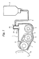
- a toner replenishing system embodying the present invention includes a developing section 1 arranged in the body of an image forming apparatus.
- a toner container 2 is communicated to the developing section 1 by toner delivering means 3 and stores toner to be replenished to the developing section 1.
- the developing section 1 includes a casing 4 storing a two-ingredient type developer D, i.e., a toner and carrier mixture.
- a first and a second screw or agitator 5 and 6, respectively, and a developing roller 7 are disposed in the casing 4.
- the developing roller 7 faces a photoconductive drum or image carrier 8.
- a latent image is electrostatically formed on the drum 8 while the drum 8 is rotated in a direction indicated by an arrow in FIG. 1.
- the two screws 5 and 6 each are rotated in a particular direction indicated by an arrow in FIG. 1, agitating the developer D and thereby charging the toner and carrier to opposite polarities.
- the charged developer D is deposited on the surface of the developing roller 7 being rotated in a direction indicated by an arrow in FIG. 1
- the developing roller 7 conveys the developer D to a developing position where the drum 8 and roller 7 face each other.
- a doctor blade 9 regulates the amount of the developer D being conveyed toward the developing position.
- the toner of the developer D is electrostatically transferred from the developing roller 7 to the latent image formed on the drum 8, thereby producing a corresponding toner image.
- the toner container 2 is removably mounted to the apparatus body.
- the air stream generating means includes an air pump or similar means for sending air into the toner container 2 (air sending means hereinafter) or a suction pump or similar means for sucking air out of the toner container 2 (air sucking means hereinafter).
- air sending means hereinafter
- suction pump or similar means for sucking air out of the toner container 2
- the operation of the air stream generating means is controllable to control the intensity of the air stream and therefore the amount of toner to be replenished.
- FIGS. 3-1 and 3-2 show a specific configuration of the nozzle 11.
- the nozzle 11 is a columnar member formed of, e.g . plastics or metal.
- the nozzle 11 has a tubular toner outlet portion 16 and a tubular air inlet portion 16 extending in the lengthwise direction of the column and each protruding from the opposite ends or the side of the column, as illustrated.
- a hole or toner outlet 15 is formed in one end of the toner outlet portion 16
- the air inlet portion 18 surrounds the toner outlet portion 16.
- the nozzle 11 has its outermost wall 17 connected to the toner outlet portion or mouth of the toner container 2, not shown, such that the hole 15 is disposed in the container 2, as will be described more specifically later.
- the nozzle 11 is connected to a toner outlet portion or mouth 13 (see FIG. 2) included in the toner container 2 while the toner outlet portion 16 is connected to the connecting member 24 by the toner conduit 12, completing the delivery passage.
- the toner container itself is formed with two holes, one for toner delivery and the other for air feed.
- a tubular structural body positioned in one hole for toner delivery is directly connected to the toner conduit 12 while the other hole is connected to an air pump via an air conduit. Air is sent into the toner container via the air feed hole by an air pump, so that toner is delivered to the developing section via the toner outlet hole.
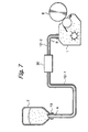
- FIG. 7 for describing the suction system in which the air sucking means is implemented by a suction pump.
- a suction pump 30 intervenes between the toner container 2 and the developing section 1, i.e., it is connected to the toner container 2 and developing section 1 by toner condu i ts 12-1 and 12-2, respectively.
- the suction pump 30 sucks the toner out of the toner container 2 and delivers it to the developing section 1 together with air.
- the suction system is similar to the blow system.
- FIG. 8 shows a specific configuration of the suction pump 30 that is generally referred to as a Mono pump.
- the pump 30 includes a pump body 30 having a casing 31 and a twisted rotary shaft 32 disposed in the casing 31. A shallow spiral groove is formed in the inner periphery of the casing 31.
- a delivery section 35 is positioned at the outlet side of the pump body 30 and includes an air inlet tube 33 and a delivery tube 34.
- a toner suction tube 36 is positioned at the suction side of the pump body 30 and connected to the mouth 13 of the toner container 2 by the toner conduit 12-1.
- the delivery tube 34 is connected to the developing sect i on 1 by the other toner conduit 12-2.
- the pump body 30 and developing section 1 may be directly connected to each other without the intermediary of the toner conduit 12-2.
- the pump 30 can sufficiently function even when it is located at a remote position from the toner container 2.
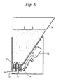
- a specific form of the toner container in accordance with the present invention is implemented by a flexible sack and a mouth or toner outlet portion affixed thereto.
- the sack is deformable due to air pressure in such a manner as to reduce its volume.
- the air sucking means starts operating, it first sucks the center portion of the container and forces the toner out of the center portion.
- toner container in accordance with the present invention will be described in detail hereinafter. While the toner container to be described was devised in relation to the above toner replenishing system of the present invention, it is similarly applicable to any other toner replenishing system. Also, various technical schemes devised for the toner container itself and the toner container filled with toner are usable to achieve the object of the present invention at a higher level and can be used alone or in combination. While the toner container will be described as being used with its mouth facing downward, it can, of course, be mounted to an image forming apparatus in any other desired position.
- the toner container of the present invention includes at least a toner storing portion and a mouth or toner outlet portion.
- the mouth includes a tubular portion capable of mating with an elongate matter.
- This kind of mouth is representative of the characteristic function of the previously described mouth connectable to one end of the toner delivering means.
- the elongate matter should only be a relatively thin columnar or tubular matter and is not limited to the toner delivering means of the toner replenishing system described above.
- the toner container with such a mouth may be implemented as a hard toner container entirely formed of a hard material or as a soft sack formed of a flexible material.
- a hard container use may be made of polyethylene, polypropylene, polyethylene terephthalate or similar resin or thick paper.
- the toner container of the present invention is characterized in that the container does not include a toner discharging mechanism because of the use of an air stream, in that the container, whether it be hard or soft, is connected to the nozzle or the toner outlet tube forming one end of the toner delivering means by mating in order to be applicable to the above toner replenishing system, and in that at least part of the mouth capable of mating with, e. g., the nozzle is provided with the previously described characteristic function.
- the tubular body When the tubular body is hard, it is usually molded integrally with a toner storing portion.
- the hard toner container of the present invention may even be one having a toner storing portion and a mouth prepared separately and removably connected together and/or having a toner storing portion connected together and/or having a toner stonng portion implemented by at least two separable parts prepared separately. In such a case, it is preferable to implement the hermetically closed condition by, e.g., threaded engagement or insertion.
- the soft toner container will be described specifically later.
- the delivery passage be closed as hermetically as possible, as stated earlier.
- the mating portion is provided with a mechanism for maintaining the engaged condition of the tubular body and, e.g., the nozzle and further enhancing the tight contact thereof. This implements the processed tubular body as distinguished from simple tubular body.
- the tight contact enhancing mechanism will be described more specifically on the assumption that it is arranged in the tubular body.
- the flat elastic member formed with slits and sized to cover the opening of the tubular body is fitted in the tubular body.
- the elastic member should preferably be adhered to the inner periphery of the tubular body.
- two elastic members which are air-permeable and not air-permeable, respectively, may be fitted in the tubular body with the air-permeable member facing the inside of the toner container.
- the prerequisite is that the slits of the two elastic members do not coincide with each other.
- the toner container is soft and emptied due to the consumption of the toner.
- the volume of the toner container decreases and sends out the toner via the slits.
- the air-permeable elastic member catches such toner and noticeably reduces the scattering of the toner.
- FIG. 11-2 shows another specific configuration in which the toner outlet 13-1 of the toner container 2 has a diameter D3 smaller than the length L of one slit 26-a of the elastic member 26.
- the elastic member 26 is formed with four slits, as illustrated.
- the slits 26-a are apt to rise and stop, e.g., the hole of the nozzle 11 when the nozzle 11 is inserted into the toner container 2
- the diameter D3 smaller than the length L solves this problem.
- FIGS. 12-1 and 12-2 and FIGS. 13-1 and 13-2 each show another specific configuration of the tight contact enhancing mechanism.
- the elastic member 26 is implemented by a packing in the form of a plate or a sheet having any desired width a.
- the elastic member 26 is affixed to the inner periphery of the tubular body 13, as shown in FIGS. 12-1 and 12-2, or to the outer periphery of the same, as shown in FIGS. 13-1 and 13-2. If desired, a plurality of elastic members 26 may be fitted on the tubular body 13.
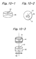
- FIGS. 14-1 through 14-3 show another specific configuration of the tight contact enhancing mechanism.
- the toner outlet of the toner container 2 is sealed by some sealing means in order to prevent the toner from leaking.
- a sheet 33 is adhered to the toner outlet of the toner container 2.
- the nozzle 11 is pressed against the sheet 33.
- the nozzle 11 enters the toner container 11 by piercing the sheet 33.
- the sheet 33 is sandwiched between the tubular body 13 and the nozzle 11, enhancing tight contact.
- the above sheet or seal 33 may be formed of rubber, aluminum or foam urethane by way of example.
- a recess may be formed at the center of the sheet 33 beforehand, so that the sheet 33 easily breaks when the nozzle 11 is inserted into the tubular body 13. It is essential with this scheme that the sheet 33 be firmly adhered to the outlet of the tubular body.
- the shoulder 13-1 may be formed in the tubular body 13 such that the tip of the nozzle 11 abuts against the shoulder 13-1. This will further promote tight contact.
- the soft toner container available with the present invention includes at least a flexible sack or toner storing portion and a rigid mouth or toner outlet portion, as stated earlier.
- the sack is designated by the reference numeral 2a in FIGS. 16-1 and 16-3. It is to be noted that the soft container of the present invention may even be one whose sack is partly flexible and partly rigid.
- the mouth expected to mate with the mating portion having the previously stated function should preferably be formed of a relatively rigid material.
- the soft toner container is deformable due to air pressure introduced thereinto, i.e., has its volume sequentially reduced by suction or sequentially increased by blow.
- the cubic shape mentioned earlier refers to the shape of the container filled with air.
- the soft toner container Before the toner container is packed with toner, the sack of the container can be substantially evacuated, i.e., reduced in volume. This allows a minimum of air to exist between toner particles dropped from a hopper, not shown, and therefore causes the toner to rapidly sink in the toner container. As a result, the total packing time is reduced, and contamination ascribable to toner is minimized.
- the toner container is protected from damage ascribable to shocks and impacts during delivery to a user. In addition, the storage and transport of such a toner container does not need a shock absorbing material which would increase costs
- FIG. 16-3 shows a specific device for allowing the air stream to easily deliver the toner from the toner container.
- the open portion of the sack 2a is fitted on the fitting portion B of the mouth.
- the open portion of the sack 2a includes a portion D having a surface substantially parallel to the surface of the fitting portion B, so that the toner easily gathers at the portion D and can be stably delivered.
- the portion D has substantially the same length as the fitting portion B although it is open to choice.
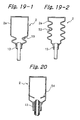
- FIG. 19-1 shows a toner conta i ner including a squeezed portion adjoining a portion of the sack 2a connected to the mouth 13.
- FIG. 19-2 shows a toner container including a plurality of squeezed portions 53 formed in the side of the sack 2a. The or each squeezed portion 53 prevents the weight of the toner above it from being transferred to the mouth 13 and thereby prevents the toner adjoining the mouth 13 from cohering while stopping relatively large masses of toner. Consequently, the toner conduit 12 and toner outlet are prevented from being stopped by the toner.
- FIGS. 25-1 and 25-2 show a modified toner container 40 similar to the toner container of FIG. 15-2.
- the toner container 40 has a sack provided with a rectangular bottom.
- One or two sides of the sack are inclined by an angle of less than 90 degrees relative to the section of the tubular body.
- the toner container 40 with this configuration has desirable volume efficiency.
- the soft toner container supported by the above position preserving means may be transported or stored alone, depending on the structure of the position preserving means.
- the present invention was closely related to the low-temperature fixing ability of toner that is the internal thermal characteristic of toner.
- toner having a flow start temperature at which the toner melts or softens is as low as about 85°C, i.e., toner with a low temperature fixing ability.
- the degree of cohesion of this kind of toner was found to depend on the kind of a toner container more than the degree of cohesion of other toner and coheres more easily.
- toner having a flow start temperature of 105°C or above depended on the kind of a toner container little. This difference presumably relates to the fact that toner with a low temperature fixing ability coheres more easily than other toner.
- Toner applicable to the toner container of the present invention has a volume mean particle size of 4.0 ⁇ m to 12.0 ⁇ m, preferably 5.0 ⁇ m to 0.9 ⁇ m. Particle sizes less than 4.0 ⁇ m would bring about problems in image transferring and cleaning steps following development. Particle sizes greater than 12.0 ⁇ m would make it difficult to maintain the resolution of an image high. For high definition images, the volume mean particles size of toner should preferably be 9.0 ⁇ m or less.
- toner with a volume mean particle size of 7.5 ⁇ m the number of fine particles of 4.0 ⁇ m or below is 18 % of the total number of particles while the weight of rough particles of 7.0 ⁇ m or above is 1.5 % of the total amount.
- toner with a volume mean particle size of 9.0 ⁇ m the number of fine particles of 4.0 ⁇ m or below is 15 % of the total number of particles while the weight of rough particles of 7.0 ⁇ m or above is 2.0 % of the total weight.
- the number of particles and weight mean particle size were measured by using Coulter TA-2 available from Coulter.
- the toner from the hopper 63 drops into air existing in the container.
- air ex i sts between toner particles and prevents them from rapidly sinking. This is apt to increase the packing time and contaminate the toner.
- the soft toner container is free from this problem because it is substantially evacuated before packing.
- pressure can be applied to the toner via the flexible sack so as to loosen the toner. It follows that while the hard container needs suction at the time of packing, the soft container can be packed with a sufficient amount of toner without any suction, in any case, the toner container packed with the toner is sealed by some method, as stated earlier.
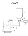
- FIG. 29 shows a specific arrangement for executing Example 1 As shown, the arrangement includes the nozzle 11 shown in FIGS. 3-1 and 3-2.
- the toner outlet port i on 16 of the nozzle 11 has an inside diameter of 6 mm and a thickness of 0.5 mm.
- the air inlet portion 18 is spaced from the toner outlet portion 16 by a gap of 1 mm and has a th i ckness of 0. 5 mm and an outs i de diameter of 9 mm.
- the toner conduit 12 is formed of EPDM to be flexibly deformable and provided with an inside diameter of 7 mm.
- the toner conduit 12 is air-tightly connected to the end of the toner outlet portion 16.
- the toner conduit 12 is 1,000 mm long and provided with a difference in level or he i ght of 300 mm between its opposite ends.
- the other end of the toner conduit 12 is fixed in place above a beaker 66 set on an electronic balance 65 (FA-2000 (trade name) available from A & D).
- FA-2000 trade name
- the air pump 10 is air-tightly connected to one end of the air inlet portion 18 by a flexible tube having an inside diameter of 5 mm and formed of EPDM.
- the air pump 10 was implemented by a diaphragm pump with a flow rate of 1. 5 1/min. (SR-01 (trade name) available from Shinmei Electric).
- a timer is connected to the air pump 10 in order to control the duration and interval of suction.
- the toner container 2 packed with toner is positioned with its mouth facing downward and connected to the nozzle 11.
- the mouth has an outlet with a diameter of 14 mm and has a tubular body with an inside diameter of 22 mm and a depth of 10 mm above the outlet.
- the nozzle 11 is inserted into the tone container 2 via the sponge such that the hole 15 of the air inlet portion 18 is positioned in the container 2.
- the toner container 2 has a hard columnar configuration formed of dense polyethylene and having a thickness of 1 mm, an outside diameter of 65 mm and a capacity of 210 cc.
- the air pump 10 is operated to deliver the toner from the toner container 2 to the beaker 66 until toner delivery from the container 2 ends.
- the weight of toner transferred to the beaker 66 was measured by the balance 60 in order to determine the amount of residual toner left in the toner container 2. It is to be noted that the air pump 10 was intermittently driven for 1 second at the intervals of 5 seconds.
- toner containers 2 respectively having pack i ng densities (g/cm 3 ) of 0.4, 0.5, 0.6, 0.7, 0.8 and 0.9.
- Toner was introduced into each container 2 by use of a spoon via a funnel inserted into the outlet of the container 2. The amount of toner is adjusted by manually vibrating the bottom of the container 2 with a metal rod.
- the above toner consisted of resin particles containing a magnetic material implemented by ion oxide and a polarity control agent, and an additive applied to the outer surfaces of the particles.
- This kind of toner is extensively used with a laser printer PC-LASER SP-10 available from Ricoh Co., Ltd.
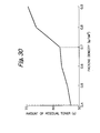
- FIG. 30 indicates, when the packing density of the toner container 2 exceeds 0.7 g/cm 3 , the amount of residual toner left in the toner container 2 at the end of delivery increases. It will therefore be seen that if the packing density is 0.7 g/cm 3 or less, the toner can be stably delivered to the developing section 1, FIG. 1, and the amount of residual toner can be minimized or practically reduced to zero. This frees the user from needless expenses.
- the amounts of residual toner appear to be substantial because they are compared with each other. In practice, the amount of residual toner can be further reduced if, e.g., the container 2 is tapered, as stated previously. This was confirmed by experiments.
- the Mono pump 30 was intermittently driven for 1 second at the intervals of 5 seconds until the toner delivery from the toner container 2 ended. Then, the amount of residual toner left in the toner container 2 was calculated. The experiment showed that the combined blow and suction type toner replenishing system was effective. As FIG. 32 indicates, when the packing density of the toner container 2 decreases below 0.7 g/cm 3 , the amount of residual toner sharply decreases.
- FIG. 33 shows the cubic shape of the above soft toner container 2
- the toner container 2 has a rectangular bottom sized 110 mm longitudinally and 80 mm laterally and has its sides inclined by an angle of about 60 degrees relative to the section of the mouth.
- the toner container 2 is 130 mm high and provided with a capacity of about 700 cc.
- the toner container 2 is foldable at the bottom and foldable vertically at the centers of two sides.
- the urethane sponge included in each of the samples [I] and [II] had a diameter of 22 mm and a thickness of 10 mm and was formed with two 12 mm wide slits intersecting each other at the center perpendicularly to each other.
- Example 5 The toner container of Example 3, FIG. 33, was also used in Example 5. The difference is that in Example 5 the 3 ⁇ m filter or pressure adjusting means 26 having a diameter of 12 mm was adhered to the bottom of the toner container 26.
- the sponge 20 was affixed to the mouth by a two-sided adhesive tape (5000N available from Nitto Denko Corp.).
- the toner container 20 was packed with 300 g of toner type S Yellow available e from Ricoh Co., Ltd.
- the toner was delivered from the toner container 2 by the combined blow and suction system.
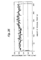
- the toner delivery from the sample [I] for a second is sometimes zero and not stable and leaves about 3. 5g of toner therein at the end.
- the toner is constantly delivered from the sample [II] by about 0.6 g for a second and left little at the end (substantially zero gram).
- the toner delivery from the sample [I] noticeably varies and causes a great amount of toner to be left in the toner container.
- FIG. 36 the toner delivery from the sample [II] is stable and causes a minimum of toner to be left in the toner container.
- the open cell sponge 20 failed to enhance tight contact between the nozzle 11 and the toner container; in fact, when the conta i ner was removed from the nozzle 11, contamination ascribable to the toner was found in the portion around the sponge 20.
- the sponge 20 with the film prevented air from leaking and thereby enhanced tight contact between the nozzle 11 and the toner container; the portion around the sponge was free from contamination.
- a toner container and a developing section can be freely laid out in an image forming apparatus, saving a limited space available in the apparatus. Further, toner can be stably replenished to the developing section at all times and is left in the toner container only in a minimum of amount.
Landscapes
- Physics & Mathematics (AREA)
- General Physics & Mathematics (AREA)
- Dry Development In Electrophotography (AREA)
Applications Claiming Priority (7)
| Application Number | Priority Date | Filing Date | Title |
|---|---|---|---|
| JP36510898 | 1998-12-22 | ||
| JP36510898 | 1998-12-22 | ||
| JP8057799 | 1999-03-24 | ||
| JP8057799 | 1999-03-24 | ||
| JP10846499 | 1999-04-15 | ||
| JP10846499 | 1999-04-15 | ||
| EP99125582A EP1014214B1 (de) | 1998-12-22 | 1999-12-21 | Tonerbehälter für Bilderzeugungsgerät |
Related Parent Applications (2)
| Application Number | Title | Priority Date | Filing Date |
|---|---|---|---|
| EP99125582A Division EP1014214B1 (de) | 1998-12-22 | 1999-12-21 | Tonerbehälter für Bilderzeugungsgerät |
| EP99125582.9 Division | 1999-12-21 |
Publications (3)
| Publication Number | Publication Date |
|---|---|
| EP1447720A2 true EP1447720A2 (de) | 2004-08-18 |
| EP1447720A3 EP1447720A3 (de) | 2007-12-05 |
| EP1447720B1 EP1447720B1 (de) | 2012-02-08 |
Family
ID=27303335
Family Applications (4)
| Application Number | Title | Priority Date | Filing Date |
|---|---|---|---|
| EP04010328A Expired - Lifetime EP1447721B1 (de) | 1998-12-22 | 1999-12-21 | Tonerbehälter und Verfahren zum Befüllen des Tonerbehälters |
| EP99125582A Expired - Lifetime EP1014214B1 (de) | 1998-12-22 | 1999-12-21 | Tonerbehälter für Bilderzeugungsgerät |
| EP04010327A Expired - Lifetime EP1447720B1 (de) | 1998-12-22 | 1999-12-21 | Tonerbehälter |
| EP04010329A Expired - Lifetime EP1445665B1 (de) | 1998-12-22 | 1999-12-21 | Elektrofotografisches Bilderzeugungsverfahren und Gerät hiermit |
Family Applications Before (2)
| Application Number | Title | Priority Date | Filing Date |
|---|---|---|---|
| EP04010328A Expired - Lifetime EP1447721B1 (de) | 1998-12-22 | 1999-12-21 | Tonerbehälter und Verfahren zum Befüllen des Tonerbehälters |
| EP99125582A Expired - Lifetime EP1014214B1 (de) | 1998-12-22 | 1999-12-21 | Tonerbehälter für Bilderzeugungsgerät |
Family Applications After (1)
| Application Number | Title | Priority Date | Filing Date |
|---|---|---|---|
| EP04010329A Expired - Lifetime EP1445665B1 (de) | 1998-12-22 | 1999-12-21 | Elektrofotografisches Bilderzeugungsverfahren und Gerät hiermit |
Country Status (10)
| Country | Link |
|---|---|
| US (4) | US6678492B1 (de) |
| EP (4) | EP1447721B1 (de) |
| JP (1) | JP4257386B2 (de) |
| KR (1) | KR100348411B1 (de) |
| CN (1) | CN1119715C (de) |
| DE (1) | DE69925701T2 (de) |
| ES (1) | ES2243029T3 (de) |
| MX (1) | MXPA00000209A (de) |
| SG (3) | SG93854A1 (de) |
| TW (6) | TWI272461B (de) |
Families Citing this family (80)
| Publication number | Priority date | Publication date | Assignee | Title |
|---|---|---|---|---|
| TWI272461B (en) * | 1998-12-22 | 2007-02-01 | Ricoh Kk | Toner container and image forming method and apparatus using the same |
| JP4157681B2 (ja) | 2000-02-14 | 2008-10-01 | 株式会社リコー | トナー収納容器 |
| CN1900837B (zh) * | 2000-02-17 | 2012-10-03 | 株式会社理光 | 墨粉收纳容器、补给墨粉的方法及墨粉补给装置 |
| US6591077B2 (en) | 2000-05-08 | 2003-07-08 | Ricoh Company, Ltd. | Image forming apparatus and toner container therefor |
| EP1607078A3 (de) * | 2000-07-18 | 2006-03-22 | Coloplast A/S | Pflaster |
| CN100422865C (zh) * | 2000-07-21 | 2008-10-01 | 株式会社理光 | 图像形成装置及墨粉收纳容器 |
| JP4351814B2 (ja) * | 2000-07-21 | 2009-10-28 | 株式会社リコー | カラー画像形成装置 |
| JP3958511B2 (ja) * | 2000-09-28 | 2007-08-15 | 株式会社リコー | トナー補給装置および画像形成装置 |
| US6665508B2 (en) * | 2001-01-31 | 2003-12-16 | Ricoh Company, Ltd. | Toner container and image forming apparatus using the same |
| US6679301B2 (en) * | 2001-03-13 | 2004-01-20 | Ricoh Company, Ltd. | Powder packing method and apparatus therefor |
| JP2002296825A (ja) * | 2001-03-30 | 2002-10-09 | Kyocera Mita Corp | 補充用トナー |
| JP4095875B2 (ja) * | 2001-10-30 | 2008-06-04 | 株式会社リコー | 現像剤収納容器及び画像形成装置 |
| US7133629B2 (en) * | 2002-04-12 | 2006-11-07 | Ricoh Company, Ltd. | Image forming method and apparatus including as easy-to-handle large capacity toner container |
| JP3741691B2 (ja) * | 2002-04-12 | 2006-02-01 | 株式会社リコー | 画像形成装置 |
| JP2003330218A (ja) * | 2002-05-17 | 2003-11-19 | Ricoh Co Ltd | トナー、トナー搬送装置及び画像形成装置 |
| US7542703B2 (en) * | 2002-05-20 | 2009-06-02 | Ricoh Company, Ltd. | Developing device replenishing a toner or a carrier of a two-ingredient type developer and image forming apparatus including the developing device |
| DE10223231A1 (de) * | 2002-05-24 | 2003-12-24 | Oce Printing Systems Gmbh | Verfahren und Vorrichtung zum Fördern von Tonermaterial aus einem Vorratsbehälter |
| JP3684212B2 (ja) | 2002-06-05 | 2005-08-17 | 株式会社リコー | 現像剤収納容器の減容方法及び現像剤補給装置並びに画像形成装置 |
| JP3974463B2 (ja) * | 2002-07-03 | 2007-09-12 | 株式会社リコー | トナーおよびこれを用いた二成分現像剤 |
| JP2004037889A (ja) * | 2002-07-04 | 2004-02-05 | Ricoh Co Ltd | 定着装置、画像形成装置およびカラー画像形成装置 |
| US7116928B2 (en) | 2002-12-18 | 2006-10-03 | Ricoh Company, Ltd. | Powder discharging device and image forming apparatus using the same |
| JP4241172B2 (ja) * | 2003-05-06 | 2009-03-18 | 株式会社リコー | トナー補給装置および画像形成装置 |
| JP2005017787A (ja) | 2003-06-27 | 2005-01-20 | Ricoh Co Ltd | トナー補給装置 |
| JP3985753B2 (ja) * | 2003-08-19 | 2007-10-03 | コニカミノルタビジネステクノロジーズ株式会社 | 画像形成装置 |
| DE10342742A1 (de) * | 2003-09-16 | 2005-05-12 | Braun Melsungen Ag | Behälter für Infusionsflüssigkeiten |
| JP2005091797A (ja) * | 2003-09-18 | 2005-04-07 | Ricoh Co Ltd | 現像方法および現像装置 |
| JP4330962B2 (ja) * | 2003-09-18 | 2009-09-16 | 株式会社リコー | 現像剤収納容器、現像剤供給装置および画像形成装置 |
| EP1584990A1 (de) * | 2004-04-05 | 2005-10-12 | Ricoh Co., Ltd. | Tonerzufuhrvorrichtung mit Gas-Zuführung |
| JP4535807B2 (ja) * | 2004-08-25 | 2010-09-01 | 株式会社リコー | 画像形成装置 |
| JP4584701B2 (ja) * | 2004-12-22 | 2010-11-24 | 株式会社リコー | 画像形成用粉体を内包する易変形性容器用容器収納箱 |
| MXPA06012659A (es) * | 2005-04-27 | 2007-01-16 | Ricoh Kk | Recipiente de toner y aparato formador de imagen. |
| WO2006132259A1 (ja) * | 2005-06-07 | 2006-12-14 | Ricoh Company, Limited | トナー容器及び画像形成装置 |
| KR100895801B1 (ko) * | 2005-10-04 | 2009-05-08 | 가부시키가이샤 리코 | 분체 공급 장치, 화상 형성 장치 및 감시 장치 |
| US8086146B2 (en) * | 2005-11-09 | 2011-12-27 | Ricoh Company, Ltd. | Image forming method and apparatus for effectively supplying developer |
| USD559893S1 (en) * | 2005-11-17 | 2008-01-15 | Casio Keisanki Kabushiki Kaisha | Pouch for retrieved waste toner |
| JP2007155841A (ja) | 2005-11-30 | 2007-06-21 | Ricoh Co Ltd | 粉体容器、トナー補給装置及び画像形成装置 |
| US7680435B2 (en) * | 2006-01-26 | 2010-03-16 | Ricoh Company, Ltd. | Flange, flange processing device, and method of processing flange |
| JP4392844B2 (ja) * | 2006-02-14 | 2010-01-06 | 株式会社リコー | 粉体供給装置及び画像形成装置 |
| JP4566147B2 (ja) * | 2006-03-06 | 2010-10-20 | シャープ株式会社 | トナー容器及びトナー充填方法 |
| JP2007238167A (ja) * | 2006-03-13 | 2007-09-20 | Ricoh Co Ltd | ストレッチラベル装着治具 |
| JP2007322916A (ja) * | 2006-06-02 | 2007-12-13 | Ricoh Co Ltd | 現像剤供給装置、現像剤容器、現像剤、及び、画像形成装置 |
| JP4990040B2 (ja) * | 2006-11-01 | 2012-08-01 | 株式会社リコー | 現像剤補給装置、画像形成装置 |
| US8050597B2 (en) * | 2006-11-09 | 2011-11-01 | Ricoh Company, Limited | Toner container having a gear portion and image forming apparatus |
| JP2008129288A (ja) * | 2006-11-20 | 2008-06-05 | Sharp Corp | トナー搬送装置および画像形成装置 |
| JP5132161B2 (ja) * | 2007-02-02 | 2013-01-30 | キヤノン株式会社 | 画像形成装置 |
| JP4680232B2 (ja) * | 2007-05-07 | 2011-05-11 | 株式会社リコー | プロセスユニット及び画像形成装置 |
| US7853173B2 (en) | 2007-10-27 | 2010-12-14 | Wazana Brothers International | Excess toner evacuation process |
| US7974557B2 (en) * | 2007-12-19 | 2011-07-05 | Xerox Corporation | Carrier replenishment and image mottle reduction system |
| JP5321112B2 (ja) * | 2008-09-11 | 2013-10-23 | 株式会社リコー | 現像装置及び画像形成装置 |
| CN103853012B (zh) | 2009-03-30 | 2017-10-24 | 佳能株式会社 | 显影剂供给容器和显影剂供给系统 |
| AU2014216008B2 (en) * | 2009-03-30 | 2015-12-03 | Canon Kabushiki Kaisha | Developer supply container and developer supplying system |
| CN102947762B (zh) * | 2010-04-27 | 2016-06-08 | 株式会社理光 | 粉体收纳容器、粉体输送装置及图像形成装置 |
| MX356824B (es) | 2011-03-30 | 2018-06-15 | Ricoh Co Ltd | Recipiente de almacenamiento de polvo y aparato de formación de imágenes. |
| JP5822061B2 (ja) | 2011-06-21 | 2015-11-24 | 株式会社リコー | 光沢付与装置、画像形成装置、カラー画像形成装置 |
| JP2013003517A (ja) | 2011-06-21 | 2013-01-07 | Ricoh Co Ltd | 光沢付与装置、定着装置、及び画像形成装置 |
| JP2013007801A (ja) | 2011-06-22 | 2013-01-10 | Ricoh Co Ltd | 光沢付与装置、及び画像形成装置 |
| KR102367636B1 (ko) | 2011-11-25 | 2022-02-28 | 가부시키가이샤 리코 | 분체 수납 용기 및 화상 형성 장치 |
| US8768223B2 (en) | 2011-12-30 | 2014-07-01 | Lexmark International, Inc. | Imaging apparatus assembly with pressure equalization |
| JP5861489B2 (ja) * | 2012-02-15 | 2016-02-16 | 株式会社リコー | 現像剤容器、現像装置、プロセスカートリッジ及び画像形成装置 |
| JP5857783B2 (ja) * | 2012-02-17 | 2016-02-10 | 株式会社リコー | ノズル、画像形成装置、及び粉体導出方法 |
| JP6019799B2 (ja) * | 2012-06-22 | 2016-11-02 | 株式会社リコー | トナー補給容器 |
| JP2014029475A (ja) * | 2012-07-06 | 2014-02-13 | Ricoh Co Ltd | トナー補給容器及びトナー補給システム |
| CN105209978B (zh) | 2013-03-14 | 2019-08-09 | 株式会社理光 | 调色剂容器和图像形成设备 |
| US8774685B1 (en) * | 2013-06-14 | 2014-07-08 | Lexmark International, Inc. | Venting system for a toner cartridge for use with an image forming device |
| US9128412B2 (en) | 2013-06-14 | 2015-09-08 | Lexmark International, Inc. | Venting system for a toner cartridge for use with an image forming device |
| JP2015041001A (ja) * | 2013-08-22 | 2015-03-02 | 株式会社リコー | 現像剤搬送装置、現像装置及び画像形成装置 |
| CN110780563B (zh) | 2014-03-17 | 2022-04-19 | 株式会社理光 | 粉末容器和图像形成设备 |
| US9217956B1 (en) * | 2014-09-15 | 2015-12-22 | Xerox Corporation | Dispense-end seal for toner containers |
| US9594331B2 (en) | 2015-02-27 | 2017-03-14 | Ricoh Company, Ltd. | Powder container and image forming apparatus incorporating same |
| US9494909B1 (en) * | 2015-08-12 | 2016-11-15 | Xerox Corporation | Toner micro-container |
| US9665064B1 (en) * | 2015-12-29 | 2017-05-30 | Grs Korea Inc. | Output apparatus with an external toner supplying device |
| JP6546559B2 (ja) * | 2016-03-31 | 2019-07-17 | 株式会社沖データ | 現像処理装置、現像装置および画像形成装置 |
| KR101827259B1 (ko) * | 2016-06-13 | 2018-02-08 | 김영준 | 레이저 프린터용 토너 커트리지 및 이를 구비한 레이저 프린터 그리고 레이저 프린터의 토너 자동 공급 시스템 |
| CN108107695B (zh) * | 2017-11-29 | 2020-09-25 | 苏州市信睦知识产权服务有限公司 | 一种碳粉填充装置 |
| KR20190125106A (ko) * | 2018-04-27 | 2019-11-06 | 휴렛-팩커드 디벨롭먼트 컴퍼니, 엘.피. | 장착된 토너 카트리지에 리필 토너 공급 |
| KR102390147B1 (ko) * | 2018-08-30 | 2022-04-25 | 휴렛-팩커드 디벨롭먼트 컴퍼니, 엘.피. | 현상 카트리지와 본체 간의 인터페이스를 통해 본체에 연결되는 토너 리필 카트리지 |
| KR20200025336A (ko) * | 2018-08-30 | 2020-03-10 | 휴렛-팩커드 디벨롭먼트 컴퍼니, 엘.피. | 토너 충전부의 유입 셔터를 선택적으로 로킹하는 구조 |
| CN111497523B (zh) * | 2019-01-31 | 2025-04-01 | 郑州三华科技实业有限公司 | 一种转盘调色机 |
| JP7646340B2 (ja) * | 2020-12-15 | 2025-03-17 | キヤノン株式会社 | トナー容器及び画像形成システム |
| JP2025091693A (ja) * | 2023-12-07 | 2025-06-19 | キヤノン株式会社 | トナー容器及び画像形成装置 |
Family Cites Families (92)
| Publication number | Priority date | Publication date | Assignee | Title |
|---|---|---|---|---|
| FR1314002A (fr) * | 1961-11-24 | 1963-01-04 | Procédé et dispositif pour distribuer une substance non compacte | |
| US4274455A (en) * | 1979-04-13 | 1981-06-23 | Tbs, Inc. | Toner loading device |
| JPS5699364A (en) | 1980-01-11 | 1981-08-10 | Olympus Optical Co Ltd | Magnet roll developing device |
| JPS5757451A (en) | 1980-09-25 | 1982-04-06 | Hitachi Ltd | Cathode-ray tube tester |
| JPS58174769A (ja) | 1982-04-07 | 1983-10-13 | Hitachi Ltd | 静止誘導電器用自動復帰形放圧装置 |
| JPS599360A (ja) | 1982-07-07 | 1984-01-18 | Nissan Motor Co Ltd | トルクコンバ−タの伝達トルク容量制御装置 |
| JPS5927558A (ja) | 1982-08-03 | 1984-02-14 | Toshiba Corp | 半導体装置用リ−ドフレ−ム |
| JPS5938459A (ja) | 1982-08-27 | 1984-03-02 | 株式会社南星 | コンクリ−トバケツトの自動着脱装置 |
| DE3232369C1 (de) * | 1982-08-31 | 1984-03-01 | Siemens AG, 1000 Berlin und 8000 München | Fixiereinrchtung zum Fixieren von Tonerbildern in einer mit Fixiermitteldampf angereicherten Atmosphaere |
| JPS6082651A (ja) | 1983-10-07 | 1985-05-10 | Sumitomo Metal Ind Ltd | 合金化溶融亜鉛めつき鋼板の製法 |
| JPS60232578A (ja) * | 1984-05-02 | 1985-11-19 | Canon Inc | 粉粒体補給用容器 |
| JPS6159464A (ja) * | 1984-08-31 | 1986-03-26 | Matsushita Electric Ind Co Ltd | トナ−補給装置 |
| JPS6159465A (ja) | 1984-08-31 | 1986-03-26 | Matsushita Electric Ind Co Ltd | トナ−補給装置 |
| JPS61122673A (ja) * | 1984-11-20 | 1986-06-10 | Fuji Xerox Co Ltd | トナ−供給装置 |
| FI72775C (fi) | 1985-08-08 | 1987-07-10 | Yhtyneet Paperitehtaat Oy | Foerfarande och anordning foer att foerbaettra en torrbandsprocess. |
| DE3633599A1 (de) | 1986-10-02 | 1988-04-07 | Siemens Ag | Vorrichtung zum einfuellen von toner aus einem transportbehaelter in einen tonervorratsbehaelter |
| DE3633593A1 (de) * | 1986-10-02 | 1988-04-07 | Siemens Ag | Vorrichtung zum verschmutzungsfreien wechseln eines tonerbehaelters in einer tonerfoerdereinrichtung eines nichtmechanischen druck- oder kopiergeraetes |
| JPS63271378A (ja) | 1987-04-30 | 1988-11-09 | Toshiba Corp | 複写機のトナ−補給装置 |
| JPH0820805B2 (ja) | 1987-08-24 | 1996-03-04 | 新電元工業株式会社 | 電子写真装置の現像装置 |
| JPS6452181U (de) | 1987-09-28 | 1989-03-30 | ||
| GB2214486A (en) * | 1988-01-20 | 1989-09-06 | John David Yair | Container |
| JPH0253055A (ja) | 1988-08-17 | 1990-02-22 | Dainippon Screen Mfg Co Ltd | 製版用画像処理装置のための接続ライン選択切換装置 |
| JPH0254392A (ja) | 1988-08-18 | 1990-02-23 | Mitsubishi Electric Corp | プリペイドカードシステム |
| JPH0269627A (ja) | 1988-09-06 | 1990-03-08 | Toyota Motor Corp | 熱電対用保護管 |
| JPH02134554U (de) * | 1989-04-12 | 1990-11-08 | ||
| JPH03156482A (ja) * | 1989-11-15 | 1991-07-04 | Seikosha Co Ltd | 磁気記録装置 |
| JPH03176303A (ja) * | 1989-11-30 | 1991-07-31 | Mita Ind Co Ltd | 粉体充填方法 |
| JPH03241372A (ja) * | 1990-02-20 | 1991-10-28 | Ricoh Co Ltd | 電子写真装置の現像器 |
| JPH049082A (ja) | 1990-04-26 | 1992-01-13 | Mita Ind Co Ltd | トナー補給装置 |
| JPH0487901A (ja) | 1990-07-18 | 1992-03-19 | Canon Inc | 粉体充填方法 |
| US5074344A (en) * | 1990-10-22 | 1991-12-24 | Eastman Kodak Company | Toner container and latchable cover |
| JPH04190267A (ja) * | 1990-11-24 | 1992-07-08 | Mita Ind Co Ltd | トナーカートリッジ |
| JPH0546022A (ja) | 1991-08-09 | 1993-02-26 | Matsushita Electric Ind Co Ltd | 現像装置 |
| JPH0588546A (ja) * | 1991-09-27 | 1993-04-09 | Ricoh Co Ltd | トナー容器 |
| JPH05170271A (ja) * | 1991-12-20 | 1993-07-09 | Ricoh Co Ltd | 補充用トナー容器 |
| JPH05232810A (ja) | 1992-02-19 | 1993-09-10 | Ricoh Co Ltd | トナー容器 |
| KR0127279B1 (ko) * | 1992-07-24 | 1997-12-29 | 사또 후미오 | 전자사진장치용 용기 및 현상장치 |
| JP2804684B2 (ja) * | 1992-08-25 | 1998-09-30 | アルプス電気株式会社 | インクカートリッジ |
| JPH06130812A (ja) * | 1992-10-22 | 1994-05-13 | Ricoh Co Ltd | トナー供給装置 |
| JPH06175490A (ja) | 1992-12-08 | 1994-06-24 | Ricoh Co Ltd | 画像形成装置 |
| JPH06175430A (ja) | 1992-12-11 | 1994-06-24 | Ricoh Co Ltd | 画像形成装置 |
| JPH06191049A (ja) * | 1992-12-25 | 1994-07-12 | Canon Inc | インクタンク、インクジェットカートリッジおよびインクジェット記録装置とインクタンクへのインク注入装置ならびにその注入方法 |
| JP3347201B2 (ja) | 1992-12-30 | 2002-11-20 | 株式会社リコー | 現像剤収納容器及び画像形成装置 |
| JPH06208301A (ja) * | 1993-01-08 | 1994-07-26 | Konica Corp | トナーカートリッジ |
| JPH06222669A (ja) | 1993-01-26 | 1994-08-12 | Ricoh Co Ltd | 画像形成装置 |
| JPH06250520A (ja) * | 1993-02-23 | 1994-09-09 | Ricoh Co Ltd | 画像形成装置 |
| US5380469A (en) | 1993-03-18 | 1995-01-10 | Calgene Chemical, Inc. | Polyglycerol esters as functional fluids and functional fluid modifiers |
| JP3225136B2 (ja) | 1993-07-31 | 2001-11-05 | 花王株式会社 | トナー補給用治具およびトナーカートリッジ |
| JP2500054B2 (ja) | 1993-10-15 | 1996-05-29 | ヤマキ工業株式会社 | 屋根材の接続構造 |
| US5474111A (en) * | 1993-10-22 | 1995-12-12 | Degussa Corporation | Fine particle handling |
| US5570170A (en) * | 1993-12-27 | 1996-10-29 | Moore Business Forms, Inc. | Electrostatic printing apparatus with a hopper and applicator roller with method of applying toner to and declumping the applicator roller |
| JP3245512B2 (ja) | 1994-03-03 | 2002-01-15 | 京セラ株式会社 | 画像形成装置 |
| US5614996A (en) | 1994-03-03 | 1997-03-25 | Kyocera Corporation | Toner storage unit, residual toner collect unit, toner container with these units and image forming apparatus with such toner container |
| JPH07261529A (ja) | 1994-03-18 | 1995-10-13 | Katsuragawa Electric Co Ltd | トナー補給装置 |
| JPH07261531A (ja) | 1994-03-19 | 1995-10-13 | Kao Corp | トナーカートリッジ |
| US5655180A (en) * | 1994-03-19 | 1997-08-05 | Kao Corporation | Toner cartridge with a rotary element which is attachable to and detachable from a developing apparatus |
| JP3904246B2 (ja) | 1994-04-08 | 2007-04-11 | 株式会社リコー | トナー補給装置及び現像装置 |
| JPH07295355A (ja) * | 1994-04-25 | 1995-11-10 | Konica Corp | トナー補給装置を備えた画像形成装置及びトナー補充容器 |
| JPH07333964A (ja) * | 1994-06-10 | 1995-12-22 | Union Kemikaa Kk | トナーカートリッジ及び詰め替え方法 |
| TW342105U (en) | 1994-07-15 | 1998-10-01 | Ricoh Co Ltd | Toner cartridge for a developing device included in an image forming apparatus |
| JPH0844174A (ja) * | 1994-07-29 | 1996-02-16 | Fujitsu Ltd | シリアル型電子写真装置 |
| US5595223A (en) * | 1994-10-21 | 1997-01-21 | Mitsubishi Pencil Corporation Of America | Ink refilling assembly |
| JP2685002B2 (ja) | 1994-11-11 | 1997-12-03 | 日本電気株式会社 | 電子写真装置のトナー補給機構 |
| MX9602780A (es) * | 1994-11-16 | 1997-06-28 | Legend Inc Ltd | Envases de fluido y metodos de fabricacion de los mismos. |
| JPH08171281A (ja) * | 1994-12-16 | 1996-07-02 | Canon Inc | 画像形成装置、プロセスカートリッジ、現像装置及び現像剤補給容器 |
| JPH08171331A (ja) * | 1994-12-16 | 1996-07-02 | Canon Inc | 画像形成装置、プロセスカートリッジ、現像装置及び現像剤補給容器 |
| JP2806848B2 (ja) * | 1995-02-22 | 1998-09-30 | 日本電気データ機器株式会社 | トナー補給機構 |
| CA2146102C (en) * | 1995-03-31 | 2000-07-25 | Hermann Ophardt | Bag fluid dispenser |
| JP3784454B2 (ja) | 1995-04-07 | 2006-06-14 | 株式会社リコー | 充填トナー補給容器及びその製造方法 |
| JPH08314272A (ja) | 1995-05-19 | 1996-11-29 | Canon Inc | 画像形成装置、プロセスカートリッジ、現像装置及び現像剤補給容器 |
| JPH096108A (ja) | 1995-06-15 | 1997-01-10 | Canon Inc | 画像形成装置のトナー補給装置 |
| JP3437332B2 (ja) | 1995-07-10 | 2003-08-18 | キヤノン株式会社 | 粉体供給用容器と該粉体供給用容器の製造方法及び粉体供給方法 |
| JPH0985962A (ja) * | 1995-09-25 | 1997-03-31 | Canon Inc | インクジェット記録装置 |
| JPH09106156A (ja) | 1995-10-09 | 1997-04-22 | Canon Inc | 現像剤容器、袋状シート及び現像剤充填装置 |
| JP3403594B2 (ja) * | 1995-11-15 | 2003-05-06 | 株式会社リコー | 画像形成装置 |
| JPH09152764A (ja) * | 1995-11-28 | 1997-06-10 | Mita Ind Co Ltd | トナーカートリッジ |
| JPH09166912A (ja) | 1995-12-18 | 1997-06-24 | Fuji Xerox Co Ltd | 画像形成装置および現像剤容器 |
| US5576816A (en) * | 1996-01-11 | 1996-11-19 | Xerox Corporation | Toner cartridge internal plug |
| JPH09305080A (ja) * | 1996-05-16 | 1997-11-28 | Mitsubishi Electric Corp | 廃トナー回収容器及び廃トナー回収装置 |
| JP3572500B2 (ja) | 1996-08-21 | 2004-10-06 | コニカミノルタホールディングス株式会社 | 現像剤補給装置及び現像剤カートリッジ |
| TW330907B (en) * | 1996-09-09 | 1998-05-01 | Riso Kagaku Corp | The ink container and ink supplied device for packing ink container |
| US5848326A (en) * | 1996-10-18 | 1998-12-08 | Ricoh Company, Ltd. | Toner conveying method and device for an image forming apparatus |
| JPH10123814A (ja) | 1996-10-24 | 1998-05-15 | Nec Niigata Ltd | トナー補給方式 |
| DE19652860C2 (de) * | 1996-12-18 | 2002-03-21 | Oce Printing Systems Gmbh | Vorrichtung zum Fördern von Tonermaterial aus einem Vorratsbehälter |
| JPH10268641A (ja) * | 1997-03-24 | 1998-10-09 | Ricoh Co Ltd | 粉体移送装置 |
| JPH10274877A (ja) * | 1997-03-31 | 1998-10-13 | Ricoh Co Ltd | 現像剤収納器及び該現像剤収納器を用いる現像剤貯蔵装置 |
| US5950055A (en) * | 1997-04-18 | 1999-09-07 | Ricoh Company, Ltd. | Powder pump and image forming apparatus having the powder pump and method therefor |
| JP3373143B2 (ja) | 1997-08-19 | 2003-02-04 | 株式会社昭和丸筒 | トナーカートリッジ |
| KR100307584B1 (ko) * | 1998-02-27 | 2001-12-12 | 윤종용 | 습식전자사진방식인쇄기용잉크공급장치 |
| US6201941B1 (en) * | 1998-06-25 | 2001-03-13 | Ricoh Company, Ltd. | Developer container for an image forming apparatus and method of conveying a developer |
| TWI272461B (en) * | 1998-12-22 | 2007-02-01 | Ricoh Kk | Toner container and image forming method and apparatus using the same |
| US6591077B2 (en) | 2000-05-08 | 2003-07-08 | Ricoh Company, Ltd. | Image forming apparatus and toner container therefor |
-
1999
- 1999-12-17 TW TW093102719A patent/TWI272461B/zh not_active IP Right Cessation
- 1999-12-17 TW TW093102715A patent/TWI272460B/zh not_active IP Right Cessation
- 1999-12-17 TW TW093102717A patent/TWI243292B/zh not_active IP Right Cessation
- 1999-12-17 TW TW093102716A patent/TWI243293B/zh not_active IP Right Cessation
- 1999-12-17 TW TW088122300A patent/TWI227815B/zh not_active IP Right Cessation
- 1999-12-17 SG SG9906411A patent/SG93854A1/en unknown
- 1999-12-17 SG SG200201573A patent/SG128420A1/en unknown
- 1999-12-17 TW TW093102718A patent/TWI251725B/zh not_active IP Right Cessation
- 1999-12-17 SG SG200201583-2A patent/SG156515A1/en unknown
- 1999-12-17 US US09/465,674 patent/US6678492B1/en not_active Expired - Lifetime
- 1999-12-21 EP EP04010328A patent/EP1447721B1/de not_active Expired - Lifetime
- 1999-12-21 EP EP99125582A patent/EP1014214B1/de not_active Expired - Lifetime
- 1999-12-21 ES ES99125582T patent/ES2243029T3/es not_active Expired - Lifetime
- 1999-12-21 DE DE69925701T patent/DE69925701T2/de not_active Expired - Lifetime
- 1999-12-21 EP EP04010327A patent/EP1447720B1/de not_active Expired - Lifetime
- 1999-12-21 EP EP04010329A patent/EP1445665B1/de not_active Expired - Lifetime
- 1999-12-22 CN CN99122934A patent/CN1119715C/zh not_active Expired - Lifetime
- 1999-12-22 KR KR1019990060272A patent/KR100348411B1/ko not_active Expired - Lifetime
-
2000
- 2000-01-04 MX MXPA00000209A patent/MXPA00000209A/es active IP Right Grant
-
2001
- 2001-07-17 US US09/907,326 patent/US6608983B2/en not_active Expired - Lifetime
-
2003
- 2003-10-24 US US10/692,547 patent/US7039346B2/en not_active Expired - Lifetime
-
2004
- 2004-03-23 US US10/806,656 patent/US7277665B2/en not_active Expired - Fee Related
-
2008
- 2008-05-23 JP JP2008135452A patent/JP4257386B2/ja not_active Expired - Lifetime
Also Published As
Similar Documents
| Publication | Publication Date | Title |
|---|---|---|
| EP1014214B1 (de) | Tonerbehälter für Bilderzeugungsgerät | |
| EP1475674B1 (de) | Bag-in-Box-Anordnung zum Speichern von Toner | |
| JP3523129B2 (ja) | トナー収納容器 | |
| JPH07261492A (ja) | 現像剤ユニット | |
| US20070122204A1 (en) | Powder container and toner replenishing device and image forming apparatus including the same | |
| JP4359482B2 (ja) | トナー収納容器及びトナー充填方法 | |
| US5907747A (en) | Prefilled, presealed toner cartridge insert | |
| JP2002002833A (ja) | 粉体収納容器および画像形成装置 | |
| JP4359483B2 (ja) | 電子写真画像形成装置 | |
| JP4113830B2 (ja) | 画像形成装置 | |
| JP4132406B2 (ja) | 画像形成装置 | |
| JP2002116612A (ja) | 現像剤補給容器 |
Legal Events
| Date | Code | Title | Description |
|---|---|---|---|
| PUAI | Public reference made under article 153(3) epc to a published international application that has entered the european phase |
Free format text: ORIGINAL CODE: 0009012 |
|
| AC | Divisional application: reference to earlier application |
Ref document number: 1014214 Country of ref document: EP Kind code of ref document: P |
|
| AK | Designated contracting states |
Kind code of ref document: A2 Designated state(s): DE ES FR GB IT NL |
|
| RIN1 | Information on inventor provided before grant (corrected) |
Inventor name: KUSANO, TETSUYA Inventor name: OGATA, FUMIO Inventor name: MURAMATSU, SATOSHI Inventor name: TERAZAWA, SEIJI Inventor name: KASAHARA, NOBUO Inventor name: TAMARU, TAKESHI |
|
| PUAL | Search report despatched |
Free format text: ORIGINAL CODE: 0009013 |
|
| AK | Designated contracting states |
Kind code of ref document: A3 Designated state(s): DE ES FR GB IT NL |
|
| 17P | Request for examination filed |
Effective date: 20080408 |
|
| AKX | Designation fees paid |
Designated state(s): DE ES FR GB IT NL |
|
| 17Q | First examination report despatched |
Effective date: 20090319 |
|
| GRAP | Despatch of communication of intention to grant a patent |
Free format text: ORIGINAL CODE: EPIDOSNIGR1 |
|
| GRAS | Grant fee paid |
Free format text: ORIGINAL CODE: EPIDOSNIGR3 |
|
| GRAA | (expected) grant |
Free format text: ORIGINAL CODE: 0009210 |
|
| AC | Divisional application: reference to earlier application |
Ref document number: 1014214 Country of ref document: EP Kind code of ref document: P |
|
| AK | Designated contracting states |
Kind code of ref document: B1 Designated state(s): DE ES FR GB IT NL |
|
| REG | Reference to a national code |
Ref country code: GB Ref legal event code: FG4D |
|
| REG | Reference to a national code |
Ref country code: DE Ref legal event code: R096 Ref document number: 69944034 Country of ref document: DE Effective date: 20120405 |
|
| REG | Reference to a national code |
Ref country code: NL Ref legal event code: VDEP Effective date: 20120208 |
|
| PG25 | Lapsed in a contracting state [announced via postgrant information from national office to epo] |
Ref country code: NL Free format text: LAPSE BECAUSE OF FAILURE TO SUBMIT A TRANSLATION OF THE DESCRIPTION OR TO PAY THE FEE WITHIN THE PRESCRIBED TIME-LIMIT Effective date: 20120208 |
|
| PG25 | Lapsed in a contracting state [announced via postgrant information from national office to epo] |
Ref country code: IT Free format text: LAPSE BECAUSE OF FAILURE TO SUBMIT A TRANSLATION OF THE DESCRIPTION OR TO PAY THE FEE WITHIN THE PRESCRIBED TIME-LIMIT Effective date: 20120208 |
|
| PLBE | No opposition filed within time limit |
Free format text: ORIGINAL CODE: 0009261 |
|
| STAA | Information on the status of an ep patent application or granted ep patent |
Free format text: STATUS: NO OPPOSITION FILED WITHIN TIME LIMIT |
|
| 26N | No opposition filed |
Effective date: 20121109 |
|
| REG | Reference to a national code |
Ref country code: DE Ref legal event code: R097 Ref document number: 69944034 Country of ref document: DE Effective date: 20121109 |
|
| PG25 | Lapsed in a contracting state [announced via postgrant information from national office to epo] |
Ref country code: ES Free format text: LAPSE BECAUSE OF FAILURE TO SUBMIT A TRANSLATION OF THE DESCRIPTION OR TO PAY THE FEE WITHIN THE PRESCRIBED TIME-LIMIT Effective date: 20120519 |
|
| REG | Reference to a national code |
Ref country code: FR Ref legal event code: PLFP Year of fee payment: 17 |
|
| REG | Reference to a national code |
Ref country code: FR Ref legal event code: PLFP Year of fee payment: 18 |
|
| REG | Reference to a national code |
Ref country code: FR Ref legal event code: PLFP Year of fee payment: 19 |
|
| PGFP | Annual fee paid to national office [announced via postgrant information from national office to epo] |
Ref country code: DE Payment date: 20181210 Year of fee payment: 20 |
|
| PGFP | Annual fee paid to national office [announced via postgrant information from national office to epo] |
Ref country code: GB Payment date: 20181218 Year of fee payment: 20 Ref country code: FR Payment date: 20181219 Year of fee payment: 20 |
|
| REG | Reference to a national code |
Ref country code: DE Ref legal event code: R071 Ref document number: 69944034 Country of ref document: DE |
|
| REG | Reference to a national code |
Ref country code: GB Ref legal event code: PE20 Expiry date: 20191220 |
|
| PG25 | Lapsed in a contracting state [announced via postgrant information from national office to epo] |
Ref country code: GB Free format text: LAPSE BECAUSE OF EXPIRATION OF PROTECTION Effective date: 20191220 |