EP1455413B1 - Procédé pour changer l'inclinaison du faisceau d'une antenne, en particulier d'une antenne d'une station de base - Google Patents
Procédé pour changer l'inclinaison du faisceau d'une antenne, en particulier d'une antenne d'une station de base Download PDFInfo
- Publication number
- EP1455413B1 EP1455413B1 EP04013187A EP04013187A EP1455413B1 EP 1455413 B1 EP1455413 B1 EP 1455413B1 EP 04013187 A EP04013187 A EP 04013187A EP 04013187 A EP04013187 A EP 04013187A EP 1455413 B1 EP1455413 B1 EP 1455413B1
- Authority
- EP
- European Patent Office
- Prior art keywords
- antenna
- depression angle
- spindle
- mobile radio
- base station
- Prior art date
- Legal status (The legal status is an assumption and is not a legal conclusion. Google has not performed a legal analysis and makes no representation as to the accuracy of the status listed.)
- Expired - Lifetime
Links
- 238000000034 method Methods 0.000 title claims abstract description 9
- 230000006870 function Effects 0.000 claims description 3
- 230000001681 protective effect Effects 0.000 abstract description 26
- 230000005855 radiation Effects 0.000 abstract description 3
- 230000005540 biological transmission Effects 0.000 description 10
- 230000001419 dependent effect Effects 0.000 description 3
- 238000001514 detection method Methods 0.000 description 2
- 238000011156 evaluation Methods 0.000 description 2
- 238000012544 monitoring process Methods 0.000 description 2
- 238000009420 retrofitting Methods 0.000 description 2
- 238000004891 communication Methods 0.000 description 1
- 238000010276 construction Methods 0.000 description 1
- 238000013461 design Methods 0.000 description 1
- 238000010586 diagram Methods 0.000 description 1
- 238000006073 displacement reaction Methods 0.000 description 1
- 230000002349 favourable effect Effects 0.000 description 1
- 238000009434 installation Methods 0.000 description 1
- 238000004519 manufacturing process Methods 0.000 description 1
Images


Classifications
-
- H—ELECTRICITY
- H01—ELECTRIC ELEMENTS
- H01Q—ANTENNAS, i.e. RADIO AERIALS
- H01Q3/00—Arrangements for changing or varying the orientation or the shape of the directional pattern of the waves radiated from an antenna or antenna system
- H01Q3/02—Arrangements for changing or varying the orientation or the shape of the directional pattern of the waves radiated from an antenna or antenna system using mechanical movement of antenna or antenna system as a whole
- H01Q3/08—Arrangements for changing or varying the orientation or the shape of the directional pattern of the waves radiated from an antenna or antenna system using mechanical movement of antenna or antenna system as a whole for varying two co-ordinates of the orientation
-
- H—ELECTRICITY
- H01—ELECTRIC ELEMENTS
- H01Q—ANTENNAS, i.e. RADIO AERIALS
- H01Q3/00—Arrangements for changing or varying the orientation or the shape of the directional pattern of the waves radiated from an antenna or antenna system
- H01Q3/26—Arrangements for changing or varying the orientation or the shape of the directional pattern of the waves radiated from an antenna or antenna system varying the relative phase or relative amplitude of energisation between two or more active radiating elements; varying the distribution of energy across a radiating aperture
- H01Q3/267—Phased-array testing or checking devices
-
- H—ELECTRICITY
- H01—ELECTRIC ELEMENTS
- H01Q—ANTENNAS, i.e. RADIO AERIALS
- H01Q1/00—Details of, or arrangements associated with, antennas
- H01Q1/12—Supports; Mounting means
- H01Q1/22—Supports; Mounting means by structural association with other equipment or articles
- H01Q1/24—Supports; Mounting means by structural association with other equipment or articles with receiving set
- H01Q1/241—Supports; Mounting means by structural association with other equipment or articles with receiving set used in mobile communications, e.g. GSM
- H01Q1/246—Supports; Mounting means by structural association with other equipment or articles with receiving set used in mobile communications, e.g. GSM specially adapted for base stations
-
- H—ELECTRICITY
- H01—ELECTRIC ELEMENTS
- H01Q—ANTENNAS, i.e. RADIO AERIALS
- H01Q3/00—Arrangements for changing or varying the orientation or the shape of the directional pattern of the waves radiated from an antenna or antenna system
- H01Q3/02—Arrangements for changing or varying the orientation or the shape of the directional pattern of the waves radiated from an antenna or antenna system using mechanical movement of antenna or antenna system as a whole
- H01Q3/04—Arrangements for changing or varying the orientation or the shape of the directional pattern of the waves radiated from an antenna or antenna system using mechanical movement of antenna or antenna system as a whole for varying one co-ordinate of the orientation
- H01Q3/06—Arrangements for changing or varying the orientation or the shape of the directional pattern of the waves radiated from an antenna or antenna system using mechanical movement of antenna or antenna system as a whole for varying one co-ordinate of the orientation over a restricted angle
-
- H—ELECTRICITY
- H01—ELECTRIC ELEMENTS
- H01Q—ANTENNAS, i.e. RADIO AERIALS
- H01Q3/00—Arrangements for changing or varying the orientation or the shape of the directional pattern of the waves radiated from an antenna or antenna system
- H01Q3/26—Arrangements for changing or varying the orientation or the shape of the directional pattern of the waves radiated from an antenna or antenna system varying the relative phase or relative amplitude of energisation between two or more active radiating elements; varying the distribution of energy across a radiating aperture
- H01Q3/30—Arrangements for changing or varying the orientation or the shape of the directional pattern of the waves radiated from an antenna or antenna system varying the relative phase or relative amplitude of energisation between two or more active radiating elements; varying the distribution of energy across a radiating aperture varying the relative phase between the radiating elements of an array
- H01Q3/32—Arrangements for changing or varying the orientation or the shape of the directional pattern of the waves radiated from an antenna or antenna system varying the relative phase or relative amplitude of energisation between two or more active radiating elements; varying the distribution of energy across a radiating aperture varying the relative phase between the radiating elements of an array by mechanical means
Definitions
- the invention relates to a method for changing a Absenkwinkels an antenna, in particular a belonging to a base station mobile radio antenna.
- the mobile radio network is designed in the form of a cell, wherein each cell is assigned a corresponding base station with at least one mobile radio antenna for transmission and reception.
- the antennas are constructed so that they usually radiate downward at a certain angle relative to the horizontal, whereby a certain cell size is determined.
- the so-called UMTS network acquires importance for the next generation of the mobile radio network, the so-called UMTS network, the 2000 MHz band.
- the antennas must be set with different angles of inclination.
- the lowering or inclination angle which is also sometimes referred to below as the downtilt angle with which a mobile radio antenna of a base station radiates downwards relative to the horizontal
- the inclination angle of the radiation pattern is changed.
- the phase shifters can be adjusted accordingly, which usually requires that the setting must be made manually on the mobile radio antenna.
- existing protective devices must be dismantled or re-assembled. This is naturally associated with a considerable installation effort.
- WO 96/14670 A1 it has also been proposed to be able to set the downtilt angle differently by means of an electrical control device, wherein the controller of such a control device can be mounted, for example, in the base of such an antenna device or used as a mobile control device, which can be connected via a plug connection, if necessary, led out of the antenna control lines to the below the protective housing built-in adjustment for adjusting the downtilt angle to press.
- the adjusting device has to be adjusted at least in the direction of a stop, in order then to travel therefrom for a predetermined distance. Due to the traveled distance then a downtilt angle is set differently depending on it.
- An antenna with a remotely controllable unit for changing the lowering angle (downtilt angle) has also become known from EP 1 067 626 A2. According to this prior publication, a sensor is used which detects the detection position of the antenna in each case in order to ultimately read from a memory the corresponding data and make the antenna setting.
- a satellite receiving antenna with an alignment capability of the antenna to a satellite for receiving programs has basically also become known from US Pat. No. 5,983,071 A. Also in this Vorverö pretung the use of memory units and interpolation is described to store certain data for controlling the satellite here and read.
- Antennas with differently adjustable Absenkwinkeln are basically also known from US 5,512,914. From US Pat. No. 6,078,824, an electromagnetic circuit device for carrying out a reduction of the emission angle can also be seen.
- the object of the present invention is therefore to provide an improved method for changing the downtilt angle.
- the method according to the invention can be used in particular in connection with an antenna control device which can be retrofitted to a corresponding mobile radio base station outside the protective housing for the radiator elements (radome).
- the manual adjustment from the outside is fundamentally state of the art.
- the control device according to the invention is preferably characterized by the fact that it interacts with cultivation outside the protective housing of the antenna exactly with that control element, via which otherwise the adjustment can be made manually.
- the antenna described in more detail with reference to embodiments uses a basically known transmission element, which can be manually operated outside the antenna protective cover, and which extends through a corresponding opening into the interior below the protective housing of the antenna to there, for example via a transmission linkage the one or to actuate the plurality of phase shifters for adjusting the downtilt angle.
- This guided from the outside to the inside through the protective housing or a part of the rear or side plate of the support and / or protective cover of the antenna actuator preferably consists of a spindle which is rotatably guided in a corresponding threaded sleeve. By turning thus the threaded spindle can be adjusted in the axial direction between two end or extreme positions.
- the method according to the invention can therefore be used in particular in connection with an antenna control device use, which is designed wholly or essentially as a complete unit or complete module. Therefore, this control device can be easily handled and mounted, and not only, as described above, in cooperation with an actuator provided outside the cover housing of the antenna device. Rather, the invention also provides that the complete unit or the complete module can also be mounted below the protective cover as a simple and easily manageable complete module if necessary and can be retrofitted if necessary. Also in this case, the retrofittable antenna control device is coupled to a corresponding actuator below the protective cover to adjust the phase angle of the antennas differently. As a significant advantage, it turns out that the antenna control device according to the invention can be mounted as a complete solution simply outside or inside the protective cover of the antenna. An assembly of a plurality of individual components possibly even at different locations below the protective cover of the antenna, as in the prior art, so falls away.
- a corresponding electronic or electrical control device is retrofitted, it is preferably mounted only outside the protective housing of the antenna. This then acts directly with the actuation transmitter, i. in particular the spindle gear provided for the manual adjustment, via which a rotation of the spindle gear can be made via the motor drive belonging to the control device.
- control electronics allocate two absolute position values to the two end stops.
- the absolute positioning can then be carried out at least in one of these two positions.
- the actuator should preferably be moved in the form of the spindle only in the respective direction until reaching the end stop. Reaching the end stop can also be detected and evaluated electrically / electronically by the control electronics.
- the transmission or actuator is preferably initially moved in the form of the spindle to at least one of the two end stops and then moved back to the other end stop, the maximum displacement path can be detected by way detection, preferably in the form of the counted rotational pulses, via the two end stops a maximum Lowering angle assigned and above each interim angle, if necessary, also be interpolated by means stored in a table support values. As a result, any positions between the extreme positions can be absolutely controlled.
- the respective current setting value can be stored in a non-volatile memory, in order then to carry out the relative adjustment when the adjustment is made again from this value.
- a control device with an outgoing interface is used. All setting and monitoring functions can be performed at the command level via this interface.
- a special controller or a computer with appropriate control software or even, for. the base station will be used.
- the mechanical and electrical / electronic parts of the control device used are coupled in a fixed relationship with each other. This requires no special addressing the control unit. Preferably, however, the control unit can also operate in a mode "with addressing”. This opens up the possibility of controlling a plurality of electronic control units from a central point via only one command interface, ie to set several angles correspondingly to different antennas.
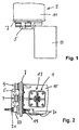
- FIG. 1 shows a schematic extractively perspective view of a mobile radio antenna for a base station. Usually arranged in a corresponding vertical orientation or slightly inclined downward in the circumferential direction lying several antenna cells radiating into different cells on a not shown in the drawings antenna mast.
- Such a mobile radio antenna may have a plurality of radiators which can radiate in different frequency bands, wherein a different angle of inclination, a so-called downtilt angle, can be adjusted by changing the phase distances between the individual vertically stacked radiators 1, with which the mobile radio antenna 3 opposite the horizontal radiates downwards. As is known, this takes place via corresponding settings of phase shifter elements, reference being made in this respect to the previously known solutions.
- a base station 71 with an antenna mast 73 is shown, to which a corresponding mobile radio antenna 3 is attached, which via Lines 75 is controlled by the base station or the command device, and about which the emission direction in an angular range ⁇ electronically more or less can be lowered.
- a corresponding mobile radio antenna 3 includes, for example, a mounting or mounting plate 5, which may also include a reflector with or at least carry a reflector, the mounting or mounting plate preferably in on its coming to lie down side with a transverse thereto terminal plate 7 is provided at which the corresponding terminals 9 are provided for connecting coaxial cables for the operation of the plurality of individual radiators.
- a generally made of FRP plastic protective cover 11 is further attached, below which the individual radiator elements are arranged sitting in front of a reflector.
- control device 13 which can be retrofitted outside the protective cover 11 is also already shown, with which the radiation angle of the antennas can be controlled or set automatically.
- FIG. 2 Before going into detail on the control device 13 shown in FIG. 1 in the installed state, reference is first made to the schematic plan view according to FIG. 2, in which a first radiator 17 is seated in front of a reflector 15 at the lower end of the reflector 15, with the protective cover 11 removed to the connection plate 7 can be seen, with the side to the 9 is provided in the terminal plate 7, an actuating opening 19, and formed by a connecting plate 7 passing through and tightly and tightly connected thereto connecting piece 23.
- This connection piece 23 is penetrated by a threaded sleeve 21, that is, in other words, the corresponding opening 19th penetrated in the connection plate 7.
- a threaded sleeve 21 is rotatably mounted about its axial axis, but held axially immovable.
- an adjusting element 25 is provided, which is formed in the embodiment shown in the form of a spindle gear 25 '.
- the threaded sleeve 21 is penetrated by an actuating element 29, which in the embodiment shown consists of a spindle 29 '.
- the external thread 29 "of the spindle 29 ' cooperates with the internal thread of the threaded sleeve 21, ie the internal thread of the spindle gear 25' together, so that by rotating the spindle gear 25 'depending on the direction of rotation, the non-rotatable spindle 29' further into the interior of the protective cover 11 axially in or out is adjusted.
- the inner end of the formed in the form of a spindle 29 'actuating element 29 is connected to a corresponding transmission means 31 in the form of a transmission linkage, wherein at the other not shown end of the transmission linkage then one or the a plurality of phase shifters for changing the inclination angle of the antennas can be set.
- a non-rotatable connection 33 is also ensured that the spindle 29 'can not turn itself.
- the adjusting member 25 in the form of the spindle gear 25 'on the outwardly facing side to the longitudinal axial axis offset radially outwardly with a first actuating end stop 35 and below the protective cover 11, ie on the inside the connecting plate 7 is equipped with an oppositely oriented also to the central axis of the spindle radially offset second actuating end stop 35 '.
- These end stops are each aligned in circumferential and thus rotational direction, wherein the outer adjustment end stop 35 with the outer on the spindle 29 'formed actuating end stop 37 and the inner adjustment end stop 35' with the inner actuating end stop 37 'cooperates , which are also aligned in the radial direction.
- the spindle is in the one end stop position, namely in the most extended position, in which the two stops 35 ', 37' abut each other.
- the downtilt angle of such an antenna can thus be easily changed manually and reset by the setting element 25, in other words, the spindle gear 25 'is rotated accordingly in the circumferential direction, thereby adjusting the spindle in the axial direction.
- the phase shifters and thus the downtilt angle can be adjusted accordingly.
- Such an antenna is also easily retrofitted with a described control device for motorized lowering of the mobile radio antenna 3, for example by means of remote control.
- control device 13 which may be equipped with the corresponding electrical or electronic components and, above all, includes the necessary drive elements for mechanical adjustment.
- the control device 13 comprises (FIG. 6) a control housing 43 with a connecting piece 45, whose connection cap ring 47, which is held over the housing 43 or the connecting piece 45 and provided with an internal thread, is firmly screwed onto a raised ring portion 23 'of the connecting piece 23 of the connecting plate 7 ,
- the mentioned spindle gear 25 'then comes to lie in the interior of the control housing 43, namely immediately adjacent to a corresponding drive gear 49, which can be driven by an electric motor 51 is.
- control electronics 41 are provided with various control boards 53 comprising the electric / electronic components for control, the operation of which will be described below.
- the control device 13 are operated accordingly.
- the spindle gear 25 ' which meshes with the drive gear 49 driven by the electric motor, is set in rotation by the electric motor 51 until the spindle 29' retracts, for example, into its innermost, ie into the protective housing 11 furthest Position is adjusted until so with the spindle gear 25 'co-moving, outer adjustment stop 35 abuts in the circumferential direction for rotation on the outer mounted on the spindle actuating end stop 37.
- the drive motor 51 is actuated in the reverse direction until the inner with the threaded sleeve 21 and the spindle gear 25 'co-rotating adjustment end stop 35' on the inner mounted on the spindle and thus axially co-moving actuating end stop 37 'abuts.
- These two end positions are assigned by the electronics two angle settings. A back and forth movement between the end stops can not lead to a blockage, since no wedging and clamping forces between the end stops occur, which strike each other virtually at 90 ° angle to each other.
- the control can be carried out in the sense of an absolute control by first moved back in the direction of an end stop and then in the opposite direction, a corresponding adjustment to the desired absolute position of the spindle 29 'is made.
- a relative adjustment can also be made in such a way that the relative value last set in each case, which corresponds to a specific lowering angle of the antenna, is preferably stored in a non-volatile intermediate memory.
- the electronics then calculate, with respect to a next value, which distance is to be taken based on the current setting got to.
- the control device 13 thus comprises in particular with the electric motor 51 electromechanical control elements and also an electronic control unit 41 for evaluation, calculation, etc.
- This so-called “intelligent" control electronics 41 preferably has an interface over which all setting / monitoring functions can be performed on a command level ,
- a special control unit or a computer with suitable control software can be used.
- the communication can be wired or wireless between a command device (such as a computer) and the control device 13, or by the base station itself.
- the address modes can be changed at any time during operation. Possibly. can also be provided that addresses can even be configured later.
- the command interface to the control electronics 41 is accessible from the outside, for example via plug or cable or it is wirelessly accessible.
- the invention has been described for an antenna control device as a complete device or as a complete module can be retrofitted outside the protective cover of the antenna.
- the same device with basically the same structure can also be mounted as a complete unit or as a complete unit or complete module within the antenna device, ie below the protective device of the antennas and coupled in the same or comparable manner with a transmission device to adjust the phase angle of the antenna elements differently , Due to the modular design or complete construction, easy and problem-free retrofitting is possible in both cases.
Landscapes
- Engineering & Computer Science (AREA)
- Computer Networks & Wireless Communication (AREA)
- Variable-Direction Aerials And Aerial Arrays (AREA)
- Details Of Aerials (AREA)
- Support Of Aerials (AREA)
- Transceivers (AREA)
Claims (18)
- Procédé pour changer l'angle d'inclinaison descendante d'une antenne radiotéléphonique mobile faisant partie d'une station de base, présentant les éléments suivants :- on exécute un auto-calibrage par rapport à la plage de réglage de l'angle d'inclinaison descendante,- on exécute l'auto-calibrage de telle sorte qu'un dispositif d'actionnement pilotable (29) est déplacé entre deux positions extrêmes ou positions terminales à l'aide d'un moteur électrique, via lequel le trajet de déplacement maximal est détecté de préférence sous forme d'impulsions rotatives comptées,- lorsqu'une position terminale correspondante est atteinte, on associe à cette position une valeur déterminée d'un angle d'inclinaison descendante maximal ou minimal, et- en fonction de la course entre les deux positions extrêmes ou positions terminales, on interpole des positions relatives intermédiaires au moyen d'une unité électronique de commande (41).
- Procédé selon la revendication 1, caractérisé en ce que l'on dépose dans une mémoire de préférence non volatile la valeur réglée respective de l'élément d'actionnement (29) et ainsi un angle d'inclinaison descendante prédéterminé de l'antenne radiotéléphonique mobile (3), et en ce qu'en cas d'une définition d'un angle d'inclinaison descendante changé, on détermine au moyen de l'unité électronique de commande (41) une valeur de pilotage relative correspondante, afin d'exécuter un déplacement à partir de la position actuelle directement vers la nouvelle position de consigne.
- Procédé selon l'une ou l'autre des revendications 1 et 2, caractérisé en ce que l'on exécute le déplacement, dépendant de la course, de l'élément d'actionnement (29) sous la forme d'une mesure de la vitesse de rotation.
- Procédé selon l'une des revendications 1 à 3, caractérisé en ce que l'on exécute toutes les fonctions de réglage et/ou de surveillance à partir
Applications Claiming Priority (3)
| Application Number | Priority Date | Filing Date | Title |
|---|---|---|---|
| DE10104564A DE10104564C1 (de) | 2001-02-01 | 2001-02-01 | Steuerungsvorrichtung zum Einstellen eines unterschiedlichen Absenkwinkels insbesondere von zu einer Basisstation gehörenden Mobilfunkantennen sowie eine zugehörige Antenne und Verfahren zur Veränderung eines Absenkwinkels |
| DE10104564 | 2001-02-01 | ||
| EP02716706A EP1356539B1 (fr) | 2001-02-01 | 2002-01-31 | Antenne de radiotelephonie mobile pour fixer un angle d'inclination different |
Related Parent Applications (1)
| Application Number | Title | Priority Date | Filing Date |
|---|---|---|---|
| EP02716706A Division EP1356539B1 (fr) | 2001-02-01 | 2002-01-31 | Antenne de radiotelephonie mobile pour fixer un angle d'inclination different |
Publications (2)
| Publication Number | Publication Date |
|---|---|
| EP1455413A1 EP1455413A1 (fr) | 2004-09-08 |
| EP1455413B1 true EP1455413B1 (fr) | 2006-06-14 |
Family
ID=7672517
Family Applications (2)
| Application Number | Title | Priority Date | Filing Date |
|---|---|---|---|
| EP02716706A Expired - Lifetime EP1356539B1 (fr) | 2001-02-01 | 2002-01-31 | Antenne de radiotelephonie mobile pour fixer un angle d'inclination different |
| EP04013187A Expired - Lifetime EP1455413B1 (fr) | 2001-02-01 | 2002-01-31 | Procédé pour changer l'inclinaison du faisceau d'une antenne, en particulier d'une antenne d'une station de base |
Family Applications Before (1)
| Application Number | Title | Priority Date | Filing Date |
|---|---|---|---|
| EP02716706A Expired - Lifetime EP1356539B1 (fr) | 2001-02-01 | 2002-01-31 | Antenne de radiotelephonie mobile pour fixer un angle d'inclination different |
Country Status (14)
| Country | Link |
|---|---|
| US (2) | US7031751B2 (fr) |
| EP (2) | EP1356539B1 (fr) |
| JP (1) | JP3913678B2 (fr) |
| KR (1) | KR100609205B1 (fr) |
| CN (1) | CN100372175C (fr) |
| AT (2) | ATE330337T1 (fr) |
| AU (1) | AU2002247672B2 (fr) |
| BR (1) | BRPI0203845B1 (fr) |
| CA (1) | CA2434369C (fr) |
| DE (3) | DE10104564C1 (fr) |
| ES (2) | ES2266959T3 (fr) |
| NZ (1) | NZ526457A (fr) |
| WO (1) | WO2002061877A2 (fr) |
| ZA (1) | ZA200207136B (fr) |
Cited By (5)
| Publication number | Priority date | Publication date | Assignee | Title |
|---|---|---|---|---|
| DE102008053851A1 (de) | 2008-10-30 | 2010-05-06 | Kathrein-Werke Kg | Antennenanlage, insbesondere Mobilfunk-Antennenanlage sowie zugehörige Übertragungs- und Steuerungseinrichtung |
| DE102008053850A1 (de) | 2008-10-30 | 2010-05-06 | Kathrein-Werke Kg | Antennenanlage, insbesondere Mobilfunk-Antennenanlage sowie zugehörige Übertragungs- und Steuerungseinrichtung |
| WO2010049094A1 (fr) | 2008-10-30 | 2010-05-06 | Kathrein-Werke Kg | Installation d'antenne à distance pour plusieurs stations de base se partageant une seule ligne d'alimentation hf pour la transmission des signaux de haute fréqneuce, de commande et de surveillance ainsi que tension continue d'alimentation |
| DE102008059333A1 (de) | 2008-11-27 | 2010-06-02 | Kathrein-Werke Kg | GPS-Mastmodul sowie Mobilfunkanlage |
| CN103872458A (zh) * | 2012-12-12 | 2014-06-18 | 中国移动通信集团北京有限公司 | 一种天线辐射波束的发射方法及装置 |
Families Citing this family (58)
| Publication number | Priority date | Publication date | Assignee | Title |
|---|---|---|---|---|
| DE19938862C1 (de) | 1999-08-17 | 2001-03-15 | Kathrein Werke Kg | Hochfrequenz-Phasenschieberbaugruppe |
| DE10104564C1 (de) | 2001-02-01 | 2002-09-19 | Kathrein Werke Kg | Steuerungsvorrichtung zum Einstellen eines unterschiedlichen Absenkwinkels insbesondere von zu einer Basisstation gehörenden Mobilfunkantennen sowie eine zugehörige Antenne und Verfahren zur Veränderung eines Absenkwinkels |
| US6573875B2 (en) | 2001-02-19 | 2003-06-03 | Andrew Corporation | Antenna system |
| FR2851694B1 (fr) * | 2003-02-24 | 2005-05-20 | Jaybeam Ltd | Antenne a commande electrique du depointage |
| DE10336073A1 (de) * | 2003-08-06 | 2005-03-10 | Kathrein Werke Kg | Antennenanordnung |
| DE10336071B3 (de) * | 2003-08-06 | 2005-03-03 | Kathrein-Werke Kg | Antennenanordnung sowie Verfahren insbesondere zu deren Betrieb |
| US7038621B2 (en) | 2003-08-06 | 2006-05-02 | Kathrein-Werke Kg | Antenna arrangement with adjustable radiation pattern and method of operation |
| US6940469B2 (en) | 2003-08-06 | 2005-09-06 | Kathrein-Werke Kg | Antenna arrangement |
| DE10336072B4 (de) * | 2003-08-06 | 2005-08-11 | Kathrein-Werke Kg | Antennenanordnung |
| US7177667B2 (en) * | 2003-11-25 | 2007-02-13 | Kmw Inc. | Antenna remote control apparatus of mobile communication base station system |
| KR101062346B1 (ko) * | 2004-07-10 | 2011-09-05 | 엘지전자 주식회사 | 이동통신 단말기의 안테나 장치 |
| US7856206B2 (en) * | 2004-09-09 | 2010-12-21 | Nextel Communications Inc. | System and method for manually adjustable directional antenna |
| SE528018C2 (sv) * | 2004-11-26 | 2006-08-08 | Powerwave Technologies Sweden | Antennstyrsystem |
| SE528015C2 (sv) | 2004-11-26 | 2006-08-08 | Powerwave Technologies Sweden | Antennstyrsystem |
| US7557675B2 (en) * | 2005-03-22 | 2009-07-07 | Radiacion Y Microondas, S.A. | Broad band mechanical phase shifter |
| DE102005061636A1 (de) | 2005-12-22 | 2007-06-28 | Kathrein-Werke Kg | Dual polarisierte Antenne |
| US7427966B2 (en) | 2005-12-28 | 2008-09-23 | Kathrein-Werke Kg | Dual polarized antenna |
| CN100559655C (zh) * | 2006-03-23 | 2009-11-11 | 京信通信技术(广州)有限公司 | 调整移动通信天线电下倾角的控制装置 |
| SE529953C2 (sv) * | 2006-05-31 | 2008-01-15 | Powerwave Technologies Sweden | Styrsystem för styrning av den elektriskt inställda lutningen hos en antenn |
| US20080186249A1 (en) * | 2006-10-31 | 2008-08-07 | Motorola, Inc. | Using a protective housing and a pressurized mechanism to protect base station antennas |
| US7812776B2 (en) * | 2006-12-19 | 2010-10-12 | Radiacion Y Microondas, S.A. | Remote control device for controlling the angle of inclination of the radiation diagram on an antenna |
| US8224241B1 (en) | 2007-07-05 | 2012-07-17 | Nextel Communications Inc. | System and method for antenna orientation for mobile applications |
| US8428511B1 (en) | 2007-08-10 | 2013-04-23 | Nextel Communications Inc. | System and method for a high available and survivable communication system |
| CN101197468B (zh) * | 2007-12-10 | 2011-06-08 | 华为技术有限公司 | 一种天线和一种基站系统 |
| DE102007060083A1 (de) | 2007-12-13 | 2009-06-18 | Kathrein-Werke Kg | Mehrspalten-Multiband-Antennen-Array |
| EP2248272A4 (fr) * | 2008-02-11 | 2013-01-16 | Amphenol Corp | Antenne à télécommande d'inclinaison électrique équipée d'un moteur et d'un bloc d'embrayage |
| DE102008059268A1 (de) | 2008-11-27 | 2009-11-19 | Kathrein-Werke Kg | Einrichtung zur Lageerkennung einer Antennenanordnung |
| US8217848B2 (en) * | 2009-02-11 | 2012-07-10 | Amphenol Corporation | Remote electrical tilt antenna with motor and clutch assembly |
| DE202009001821U1 (de) | 2009-02-12 | 2009-04-16 | Kathrein-Werke Kg | Antenne, insbesondere Mobilfunkantenne |
| KR101605860B1 (ko) * | 2009-05-12 | 2016-03-24 | 주식회사 에이스테크놀로지 | 안테나에 있어서 도브 테일 장치 |
| CN101944648B (zh) * | 2009-07-10 | 2013-06-26 | 华为技术有限公司 | 天线安装架 |
| US8391926B2 (en) * | 2010-03-26 | 2013-03-05 | Kathrein-Werke Kg | Multi-beam-shaping structure |
| DE102010012991B4 (de) | 2010-03-26 | 2011-12-15 | Kathrein-Werke Kg | Multi-Strahlformeinrichtung |
| CN102055069B (zh) * | 2010-11-01 | 2014-10-29 | 京信通信系统(中国)有限公司 | 电调天线控制系统及方法 |
| CN104966902B (zh) | 2010-11-23 | 2017-11-21 | 华为技术有限公司 | 天线装置、天线系统和天线电调方法 |
| DE102011009600B3 (de) * | 2011-01-27 | 2012-03-15 | Kathrein-Werke Kg | Mobilfunkantenne mit Multi-Strahlformeinrichtung |
| DE102011015572B3 (de) | 2011-03-30 | 2012-06-28 | Kathrein-Werke Kg | Strahlformeinrichtung für eine Antenne sowie zugehörige Antenne |
| DE102011015551B4 (de) | 2011-03-30 | 2012-12-20 | Kathrein-Werke Kg | Multi-Strahlform-Zusatzeinrichtung |
| DE102011015550B4 (de) | 2011-03-30 | 2012-10-31 | Kathrein-Werke Kg | Multi-Strahlform-Steuerungseinrichtung |
| CN102263328B (zh) * | 2011-06-07 | 2014-09-03 | 华为技术有限公司 | 一种多频天线远程控制设备及多频天线系统 |
| CN103151598B (zh) * | 2011-12-07 | 2015-03-04 | 中国电信股份有限公司 | 基站天线俯仰角调节装置和方法 |
| US9130264B2 (en) | 2012-05-09 | 2015-09-08 | Jeffrey Gervais | Apparatus for raising and lowering antennae |
| WO2013181824A1 (fr) * | 2012-06-07 | 2013-12-12 | 华为技术有限公司 | Procédé, dispositif et système d'inclinaison électrique |
| DE102013009224A1 (de) | 2013-05-31 | 2014-12-04 | Kathrein-Werke Kg | Modulare Verstelleinrichtung, insbesondere für HF-Geräte |
| DE102014002169A1 (de) * | 2014-02-19 | 2015-08-20 | Kathrein-Werke Kg | Antenne, insbesondere Mobilfunkantenne |
| WO2016158769A1 (fr) * | 2015-03-31 | 2016-10-06 | 日本電業工作株式会社 | Antenne et dispositif de commande de déphasage |
| JP2016195324A (ja) * | 2015-03-31 | 2016-11-17 | 日本電業工作株式会社 | アンテナおよび移相制御装置 |
| DE102015004658A1 (de) | 2015-04-13 | 2016-10-13 | Kathrein-Werke Kg | Differenz-Phasenschieberbaugruppe |
| EP3096393B1 (fr) | 2015-05-22 | 2018-01-24 | Kathrein Werke KG | Bloc dephaseur differentiel |
| WO2016191875A1 (fr) * | 2015-06-04 | 2016-12-08 | Griffin Innovation | Dispositif et procédé de commande d'une pluralité de dispositifs ciblés |
| DE202015105535U1 (de) | 2015-10-19 | 2015-11-27 | Kathrein Werke Kg | Verstellelement zur Verwendung in Mobilfunkantennen und Mobilfunkantenne mit Verstellelement |
| DE102018113101A1 (de) | 2018-06-01 | 2019-12-05 | Kathrein Se | Elektrisch adressierbares Kupplungs-Modul, insbesondere für einstellbare Mobilfunk-Baugruppen |
| CN110970731A (zh) | 2018-09-30 | 2020-04-07 | 华为技术有限公司 | 调节装置、天线及通信设备 |
| CN109579774B (zh) * | 2018-11-06 | 2021-04-23 | 五邑大学 | 一种基于深度实例分割网络的天线下倾角测量方法 |
| CN109975641B (zh) * | 2019-05-06 | 2021-01-12 | 南京金信智能科技有限公司 | 一种高精度、高效率天线罩测试系统 |
| EP4471983A4 (fr) * | 2022-01-25 | 2026-03-11 | Kmw Inc | Appareil d'antenne de station de base de petite cellule |
| US20260237913A1 (en) * | 2023-02-06 | 2026-08-13 | Telefonaktiebolaget Lm Ericsson (Publ) | Improved steering of antenna beam pointing directions |
| CN119828770B (zh) * | 2023-10-07 | 2026-02-03 | 荣耀终端股份有限公司 | 天线转动控制方法及相关设备 |
Family Cites Families (269)
| Publication number | Priority date | Publication date | Assignee | Title |
|---|---|---|---|---|
| US1806755A (en) | 1931-05-26 | Antenna | ||
| FR959833A (fr) | 1950-04-06 | |||
| US1764441A (en) | 1924-08-04 | 1930-06-17 | Hahnemann Walter | Arrangement for directional transmission and reception by means of electric waves |
| DE584383C (de) | 1927-10-28 | 1933-09-19 | Rca Corp | Richtantenne fuer kurze Wellen |
| US2041600A (en) | 1934-04-05 | 1936-05-19 | Bell Telephone Labor Inc | Radio system |
| US2245660A (en) | 1938-10-12 | 1941-06-17 | Bell Telephone Labor Inc | Radio system |
| US2272431A (en) | 1939-06-17 | 1942-02-10 | Rca Corp | Directional antenna orientation control |
| US2247666A (en) | 1939-08-02 | 1941-07-01 | Bell Telephone Labor Inc | Directional antenna system |
| US2248335A (en) | 1939-11-28 | 1941-07-08 | Burkhart William Shearman | Radio beam antenna and control means therefor |
| US2300576A (en) | 1940-01-06 | 1942-11-03 | Internat Telephone & Radio Mfg | Loop-automatic and manual drive |
| DE908748C (de) | 1940-08-22 | 1954-04-08 | Blaupunk Elektronik G M B H | Einrichtung zur Einstellung der Phasenlage einer elektromagnetischen Schwingung in einem Hohlleiter |
| DE945261C (de) | 1942-03-11 | 1956-07-05 | Elektronik Ges Mit Beschraenkt | Einrichtung zur Einstellung der Phasenlage einer elektromagnetischen Schwingung in einem Hohlleiter |
| CH275290A (fr) | 1943-08-09 | 1951-05-15 | Telephon Et Radio S A Standard | Installation de réception à haute fréquence ayant une directivité variable en azimut. |
| US2648000A (en) | 1943-10-02 | 1953-08-04 | Us Navy | Control of wave length in wave guides |
| US2462881A (en) | 1943-10-25 | 1949-03-01 | John W Marchetti | Antenna |
| US2605413A (en) | 1943-11-10 | 1952-07-29 | Luis W Alvarez | Antenna system with variable directional characteristic |
| US2432134A (en) | 1944-06-28 | 1947-12-09 | American Telephone & Telegraph | Directional radio system |
| US2496920A (en) | 1944-07-29 | 1950-02-07 | Rca Corp | Phase shifter |
| US2583747A (en) | 1946-01-26 | 1952-01-29 | Gordon Specialties Company | Rotary antenna |
| US2596966A (en) | 1948-11-16 | 1952-05-13 | Gilfillan Bros Inc | Radar antenna structure |
| US2566897A (en) | 1948-11-22 | 1951-09-04 | Herbert G Koenig | Electrical rotating apparatus for directional antennae |
| US2565334A (en) | 1949-06-09 | 1951-08-21 | Weingarden Herbert | Antenna setting device |
| US2535850A (en) | 1949-06-24 | 1950-12-26 | Hammond Instr Co | Radio antenna apparatus |
| US2540696A (en) | 1949-07-16 | 1951-02-06 | Jr Walter J Smith | Drive mechanism for adjustable antennas |
| US2642567A (en) | 1949-09-22 | 1953-06-16 | Bendix Aviat Corp | Control system |
| US2597424A (en) | 1949-11-15 | 1952-05-20 | Thomas P Welsh | Antenna orientation control |
| US2736854A (en) | 1949-11-25 | 1956-02-28 | Crown Controls Company Inc | Motor operated device and remote control therefor |
| US2599048A (en) | 1950-05-10 | 1952-06-03 | Oscar H Dicke | Antenna rotating and/or tuning apparatus |
| US2594115A (en) | 1950-05-22 | 1952-04-22 | Aberney Corp | Rotatably adjustable antenna |
| US2830292A (en) | 1950-12-29 | 1958-04-08 | Marvin P Young | Device to position a communications antenna |
| US2745994A (en) | 1951-05-12 | 1956-05-15 | Crown Controls Company Inc | Antenna position control means and indicator |
| US2711527A (en) | 1951-06-07 | 1955-06-21 | Donald B Alexander | Directional control mechanism for antennas |
| US2668920A (en) | 1951-08-22 | 1954-02-09 | Edward L Barrett | Antenna rotator |
| NL173647B (nl) | 1951-11-08 | Naphtachimie Sa | Werkwijze voor de bereiding van katalysatoren voor de polymerisatie van alkenen, werkwijze voor de bereiding van polymeren of copolymeren en gevormde voortbrengselen, vervaardigd onder toepassing van de aldus bereide polymeren of copolymeren. | |
| US2836814A (en) | 1952-06-25 | 1958-05-27 | Itt | R-f phase shifter |
| US2773254A (en) | 1953-04-16 | 1956-12-04 | Itt | Phase shifter |
| US3008140A (en) | 1953-06-10 | 1961-11-07 | Joseph K Rose | Means for independent orientation of antennas on a mast |
| US2787169A (en) | 1954-01-28 | 1957-04-02 | Robert E Farr | Antenna rotating means |
| US2789190A (en) | 1954-05-17 | 1957-04-16 | Statham Lab Inc | Motion sensing device |
| US2861235A (en) | 1954-06-22 | 1958-11-18 | Cornell Dubilier Electric | Servosystem control unit for antenna rotators |
| CH320969A (de) | 1954-07-31 | 1957-04-15 | Patelhold Patentverwertung | Mikrowellenleitung mit veränderbarer elektrischer Länge |
| US2968808A (en) | 1954-08-24 | 1961-01-17 | Alford Andrew | Steerable antenna array |
| US2825240A (en) | 1954-10-14 | 1958-03-04 | Radiart Corp | Hydraulic antenna rotator |
| US2794162A (en) | 1954-11-17 | 1957-05-28 | Robert J Lifsey | Television antenna rotating servo system |
| US2815501A (en) | 1955-02-18 | 1957-12-03 | Jfd Mfg Co Inc | Antenna rotator system and control unit therefor |
| DE1033280B (de) | 1955-03-17 | 1958-07-03 | Csf | Funkpeileinrichtung mit Amplitudenvergleich bei elektrisch geschwenkter Minimumcharakteristik |
| US2851620A (en) | 1955-08-04 | 1958-09-09 | Ohio Commw Eng Co | Step-by-step motor for positioning television antennae |
| US2922941A (en) | 1955-12-21 | 1960-01-26 | Howard W Sams & Co Inc | Automatic motor control unit |
| US2900154A (en) | 1956-03-06 | 1959-08-18 | Walter C Schweim | Manual rotator for antenna |
| US2931169A (en) * | 1956-05-15 | 1960-04-05 | Westinghouse Electric Corp | Variable convergent-divergent exhaust nozzle |
| US2872631A (en) | 1956-07-02 | 1959-02-03 | Thompson Prod Inc | Rotation control system |
| US3032759A (en) | 1956-08-31 | 1962-05-01 | North American Aviation Inc | Conical scanning system |
| DE1768660U (de) | 1957-02-15 | 1958-06-19 | Wilhelm Sihn Jun K G | Vorrichtung zur ferneinstellung einer drehbaren richtantenne. |
| US2939335A (en) | 1957-06-24 | 1960-06-07 | Braund Charles Lee | Antenna rotating apparatus |
| US3005985A (en) | 1957-09-19 | 1961-10-24 | Seymour B Cohn | Pre-programmed scanning antenna |
| DE1044789B (de) | 1957-12-13 | 1958-11-27 | Basf Ag | Verfahren zur Herstellung von feinverteiltem, basischem Kupferchlorid |
| US3032763A (en) | 1958-12-19 | 1962-05-01 | Carlyle J Sletten | Stretch array for scanning |
| US3205419A (en) | 1960-04-25 | 1965-09-07 | Theodore R Cartwright | Antenna rotation device |
| US3043998A (en) | 1960-10-03 | 1962-07-10 | Lawrence M Lunn | Selective remote position control servosystem |
| DE1826656U (de) | 1960-11-17 | 1961-02-16 | Guenther Penschuck | Vorrichtung zum fernantrieb fuer drehantennen. |
| DE1133775B (de) | 1961-01-10 | 1962-07-26 | Andreas Angermeier | Hydraulisch gesteuerte Vorrichtung zum Ferneinstellen von Richtantennen |
| US3248736A (en) | 1962-10-16 | 1966-04-26 | Channel Master Corp | Electrically directable multi-band antenna |
| NL301154A (fr) | 1962-11-29 | |||
| US3276018A (en) | 1963-05-08 | 1966-09-27 | Jesse L Butler | Phase control arrangements for a multiport system |
| GB1029865A (en) | 1963-09-03 | 1966-05-18 | Crown Controls Corp | Remote control system for antenna rotators |
| US3316469A (en) | 1963-09-03 | 1967-04-25 | Crown Controls Corp | Plural motor remote control system |
| US3277481A (en) | 1964-02-26 | 1966-10-04 | Hazeltine Research Inc | Antenna beam stabilizer |
| FR1570415A (fr) | 1965-11-29 | 1969-06-13 | ||
| US3491363A (en) | 1966-02-14 | 1970-01-20 | Lockheed Aircraft Corp | Slotted waveguide antenna with movable waveguide ridge for scanning |
| US3438035A (en) | 1966-08-08 | 1969-04-08 | Itt | Pencil beam frequency/phase scanning system |
| US3508274A (en) | 1966-12-14 | 1970-04-21 | Raymond B Kesler | Motor driven portable dipole antenna |
| US3527993A (en) | 1968-02-12 | 1970-09-08 | Jerrold Electronics Corp | Solid state motor driven antenna rotator control circuit |
| US3673606A (en) | 1969-08-26 | 1972-06-27 | Hazeltine Corp | Flush mounted steerable array antenna |
| DE1955328C3 (de) | 1969-11-04 | 1980-12-18 | Brown, Boveri & Cie Ag, 6800 Mannheim | In der Länge stufenlos verstellbare Umwegleitung |
| GB1406994A (en) | 1971-10-11 | 1975-09-24 | Rca Corp | Indicator drive for automatic rotator |
| US3728733A (en) | 1972-02-24 | 1973-04-17 | J Robinson | Beam antenna selectively oriented to vertical or horizontal position |
| US3803625A (en) | 1972-12-18 | 1974-04-09 | Itt | Network approach for reducing the number of phase shifters in a limited scan phased array |
| US3921177A (en) | 1973-04-17 | 1975-11-18 | Ball Brothers Res Corp | Microstrip antenna structures and arrays |
| US3826964A (en) | 1973-06-28 | 1974-07-30 | Nasa | Digital servo controller |
| US3864689A (en) | 1973-08-02 | 1975-02-04 | David W Young | Hybrid scan antenna |
| US3886559A (en) | 1973-12-20 | 1975-05-27 | Milton Spirt | Remotely operated tv receiver antennae |
| US3886560A (en) | 1974-05-31 | 1975-05-27 | Tandy Corp | Antenna swivel mount |
| DE2458477C3 (de) | 1974-12-10 | 1979-01-18 | Deutsche Forschungs- Und Versuchsanstalt Fuer Luft- Und Raumfahrt E.V., 5000 Koeln | Mechanischer Mehrkanal-Phasenschieber |
| US3969729A (en) | 1975-03-17 | 1976-07-13 | International Telephone And Telegraph Corporation | Network-fed phased array antenna system with intrinsic RF phase shift capability |
| GB1505074A (en) | 1975-05-30 | 1978-03-22 | British Aircraft Corp Ltd | Receiving and/or transmitting aerial systems |
| DE2625062C3 (de) | 1976-06-03 | 1982-03-11 | Siemens AG, 1000 Berlin und 8000 München | Phasengesteuerte Antennenanordnung |
| DE2631273C3 (de) | 1976-07-12 | 1979-05-10 | Siemens Ag, 1000 Berlin Und 8000 Muenchen | Mechanisch gesteuerter Hohlleiterphasenschieber |
| US4241352A (en) | 1976-09-15 | 1980-12-23 | Ball Brothers Research Corporation | Feed network scanning antenna employing rotating directional coupler |
| US4129872A (en) | 1976-11-04 | 1978-12-12 | Tull Aviation Corporation | Microwave radiating element and antenna array including linear phase shift progression angular tilt |
| US4101902A (en) | 1976-11-10 | 1978-07-18 | Thomson-Csf | Electronic scanning antenna |
| US4077000A (en) | 1977-01-13 | 1978-02-28 | Grubbs Jerry A | Directional antenna azimuth control system |
| GB1577939A (en) | 1977-05-27 | 1980-10-29 | Plessey Co Ltd | Communication systems |
| DE2737714C2 (de) | 1977-08-22 | 1981-10-29 | Siemens AG, 1000 Berlin und 8000 München | Hochfrequenz-Phasenschieber für elektronisch phasengesteuerte Antennen |
| US4163235A (en) | 1977-08-29 | 1979-07-31 | Grumman Aerospace Corporation | Satellite system |
| US4263539A (en) | 1977-10-04 | 1981-04-21 | Zenith Radio Corporation | Automatic antenna positioning apparatus |
| GB2026204B (en) | 1978-05-31 | 1982-09-02 | Montorio Salvatore | Device for the remote control of the angular position of a rotable aerial |
| IT1108307B (it) | 1978-09-25 | 1985-12-09 | Indesit | Perfezionamenti a dispositivi di selezione di segnali con memoria |
| US4178581A (en) | 1978-11-03 | 1979-12-11 | The Bendix Corporation | Integrated antenna aperture |
| GB2034525B (en) | 1978-11-17 | 1983-03-09 | Marconi Co Ltd | Microwave transmission systems |
| US4338606A (en) | 1978-12-21 | 1982-07-06 | Sony Corporation | Antenna system with variable directivity |
| DE2855623A1 (de) | 1978-12-22 | 1980-07-03 | Licentia Gmbh | Weitbereichs-3d-radar |
| US4335388A (en) | 1979-02-21 | 1982-06-15 | Ford Aerospace & Communications Corp. | Null control of multiple beam antenna |
| GB2044567B (en) | 1979-03-02 | 1983-05-05 | Edginton A R G | Aerial direction selectors |
| US4314250A (en) | 1979-08-03 | 1982-02-02 | Communications Satellite Corporation | Intermodulation product suppression by antenna processing |
| US4301397A (en) | 1980-04-24 | 1981-11-17 | Cornell-Dubilier Electric Corporation | DC Antenna rotator system |
| US4316195A (en) | 1980-09-19 | 1982-02-16 | The United States Of America As Represented By The Secretary Of The Army | Rotating dual frequency range antenna system |
| DE3102110A1 (de) | 1981-01-23 | 1982-08-19 | Licentia Patent-Verwaltungs-Gmbh, 6000 Frankfurt | Phasengesteuerte gruppenantenne |
| US4460897A (en) | 1981-04-02 | 1984-07-17 | Bell Telephone Laboratories, Incorporated | Scanning phased array antenna system |
| JPS57184303U (fr) | 1981-05-19 | 1982-11-22 | ||
| US4413263A (en) | 1981-06-11 | 1983-11-01 | Bell Telephone Laboratories, Incorporated | Phased array antenna employing linear scan for wide angle orbital arc coverage |
| JPS6237417Y2 (fr) | 1981-06-15 | 1987-09-24 | ||
| US4427984A (en) | 1981-07-29 | 1984-01-24 | General Electric Company | Phase-variable spiral antenna and steerable arrays thereof |
| DE3134219A1 (de) | 1981-08-29 | 1983-03-10 | Wilhelm Sihn jr. KG, 7532 Niefern-Öschelbronn | Verfahren und schaltungsanordnung zur fernsteuerung von empfangsantennen |
| US4467328A (en) | 1981-10-26 | 1984-08-21 | Westinghouse Electric Corp. | Radar jammer with an antenna array of pseudo-randomly spaced radiating elements |
| US4446463A (en) | 1982-02-24 | 1984-05-01 | The United States Of America As Represented By The Secretary Of The Navy | Coaxial waveguide commutation feed network for use with a scanning circular phased array antenna |
| GB2115984B (en) | 1982-03-01 | 1986-09-24 | Raytheon Co | Transceiver element |
| US4635062A (en) | 1982-03-01 | 1987-01-06 | Raytheon Company | Transceiver element for phased array antenna |
| US4496890A (en) | 1982-03-11 | 1985-01-29 | Gerard A. Wurdack & Associates, Inc. | Antenna rotator controller |
| JPS5911495A (ja) | 1982-07-12 | 1984-01-21 | 株式会社アペツクス | 飲料自動販売機の材料ストツク機構 |
| US4536766A (en) | 1982-09-07 | 1985-08-20 | Hazeltine Corporation | Scanning antenna with automatic beam stabilization |
| US4532518A (en) | 1982-09-07 | 1985-07-30 | Sperry Corporation | Method and apparatus for accurately setting phase shifters to commanded values |
| JPS5946048U (ja) | 1982-09-17 | 1984-03-27 | 日本マランツ株式会社 | 受信機 |
| US4542326A (en) | 1982-10-08 | 1985-09-17 | Heath Company | Automatic antenna positioning system |
| JPS5990401U (ja) | 1982-12-07 | 1984-06-19 | 太田 正之 | 死節及び半死節の除去装置 |
| AU565039B2 (en) | 1983-05-23 | 1987-09-03 | Hazeltine Corp. | Resonant waveguide aperture manifold |
| US4543583A (en) | 1983-06-06 | 1985-09-24 | Gerard A. Wurdack & Associates, Inc. | Dipole antenna formed of coaxial cable |
| US4581614A (en) | 1983-07-18 | 1986-04-08 | General Electric Company | Integrated modular phased array antenna |
| JPH0779476B2 (ja) | 1983-09-08 | 1995-08-23 | 日本電気株式会社 | 輝度信号色信号分離回路 |
| NL8303444A (nl) | 1983-10-07 | 1985-05-01 | Hollandse Signaalapparaten Bv | Fasedraaier-sturing voor een phased-array antenne. |
| US4652887A (en) | 1983-12-16 | 1987-03-24 | The General Electric Company P.L.C. | Antenna drive |
| US4564824A (en) | 1984-03-30 | 1986-01-14 | Microwave Applications Group | Adjustable-phase-power divider apparatus |
| US4570134A (en) | 1984-04-19 | 1986-02-11 | Rca Corporation | Compact hybrid providing quadrature phase relation between two outputs |
| US4575697A (en) | 1984-06-18 | 1986-03-11 | Sperry Corporation | Electrically controlled phase shifter |
| GB2161026A (en) | 1984-06-29 | 1986-01-02 | Racal Antennas Limited | Antenna arrangements |
| US4602227A (en) | 1984-07-30 | 1986-07-22 | Rca Corporation | Coaxial LC phase-shifter for phase-controlled television broadcast switching circuit |
| US4617572A (en) | 1984-08-14 | 1986-10-14 | Albert Hugo | Television dish antenna mounting structure |
| JPS6193703U (fr) | 1984-11-26 | 1986-06-17 | ||
| US4616195A (en) | 1985-03-08 | 1986-10-07 | Hughes Aircraft Company | Coaxial phase shifter for transverse electromagnetic transmission line |
| GB2205946B (en) | 1985-03-21 | 1991-06-19 | Donald Christian Knudsen | Digital delay generator for sonar and radar beam formers |
| DE3678861D1 (de) | 1985-03-25 | 1991-05-29 | Toshiba Kawasaki Kk | Empfangsanordnung fuer satellitensendungen. |
| US4862179A (en) | 1985-03-26 | 1989-08-29 | Trio Kabushiki Kaisha | Satellite receiver |
| JPS61172411U (fr) | 1985-04-17 | 1986-10-27 | ||
| FR2581255B1 (fr) | 1985-04-30 | 1989-01-06 | Onera (Off Nat Aerospatiale) | Dephaseur en micro-ondes, notamment en ondes millimetriques, a commande piezoelectrique |
| FR2581254B1 (fr) | 1985-04-30 | 1988-09-16 | Onera (Off Nat Aerospatiale) | Dephaseur en micro-ondes, notamment en ondes millimetriques, a commande piezoelectrique et antennes l'utilisant |
| DE3522404A1 (de) | 1985-06-22 | 1987-01-02 | Bosch Gmbh Robert | Parabolspiegel-empfangsantenne |
| SU1337951A1 (ru) | 1985-07-26 | 1987-09-15 | Предприятие П/Я В-2749 | Канальное командное устройство фазированной антенной решетки |
| US4717918A (en) | 1985-08-23 | 1988-01-05 | Harris Corporation | Phased array antenna |
| GB2181304B (en) | 1985-10-03 | 1989-09-27 | Gen Electric Plc | Antenna feed polariser |
| US5077560A (en) | 1986-02-19 | 1991-12-31 | Sts Enterprises, Inc. | Automatic drive for a TVRO antenna |
| US4694773A (en) | 1986-03-07 | 1987-09-22 | Jgb Industries, Inc. | Remote control tilting system for raising and lowering radar and radio arch for boats |
| US4670756A (en) | 1986-04-07 | 1987-06-02 | Hazeltine Corporation | Phase shifter control |
| US4724440A (en) | 1986-05-30 | 1988-02-09 | Hazeltine Corporation | Beam steering unit real time angular monitor |
| GB8613322D0 (en) | 1986-06-02 | 1986-07-09 | British Broadcasting Corp | Array antenna & element |
| FR2706680B1 (fr) | 1986-07-04 | 1995-09-01 | Onera (Off Nat Aerospatiale) | Déphaseur hyperfréquence à microruban et diélectrique suspendu, et application à des réseaux d'antennes à balayage de lobe. |
| US4830192A (en) | 1986-08-04 | 1989-05-16 | The Coca-Cola Company | Methods of discriminating between contaminated and uncontaminated containers |
| FR2603426A1 (fr) | 1986-09-03 | 1988-03-04 | Baud Christian | Appareil d'orientation automatique d'un recepteur de signaux hyperfrequence |
| US4814774A (en) | 1986-09-05 | 1989-03-21 | Herczfeld Peter R | Optically controlled phased array system and method |
| US4717930A (en) * | 1986-10-14 | 1988-01-05 | Wheeler Alton D | Instant photography with superimposed graphics |
| GB2196484B (en) | 1986-10-24 | 1990-07-11 | Marconi Co Ltd | Phased array antenna system |
| JPH0537222Y2 (fr) | 1986-11-04 | 1993-09-21 | ||
| SE458569B (sv) | 1987-02-25 | 1989-04-10 | Erik Eklund | Rotatoranordning foer antennmaster |
| US4849763A (en) | 1987-04-23 | 1989-07-18 | Hughes Aircraft Company | Low sidelobe phased array antenna using identical solid state modules |
| US4882587A (en) | 1987-04-29 | 1989-11-21 | Hughes Aircraft Company | Electronically roll stabilized and reconfigurable active array system |
| US4791428A (en) | 1987-05-15 | 1988-12-13 | Ray J. Hillenbrand | Microwave receiving antenna array having adjustable null direction |
| US4804899A (en) | 1987-05-18 | 1989-02-14 | Gerard A. Wurdack & Associates, Inc. | Antenna rotator controllers and conversion systems therefor |
| US4755778A (en) | 1987-06-12 | 1988-07-05 | Sage Laboratories, Inc. | Microwave apparatus |
| US4815774A (en) * | 1987-07-24 | 1989-03-28 | Frank Correnti | Universal dead bolt |
| US4941200A (en) | 1987-08-03 | 1990-07-10 | Orion Industries, Inc. | Booster |
| JPH01140802A (ja) | 1987-11-27 | 1989-06-02 | Toshiba Corp | 平面アンテナ |
| US5281974A (en) | 1988-01-11 | 1994-01-25 | Nec Corporation | Antenna device capable of reducing a phase noise |
| US5021798A (en) | 1988-02-16 | 1991-06-04 | Trw Inc. | Antenna with positionable reflector |
| US4788515A (en) | 1988-02-19 | 1988-11-29 | Hughes Aircraft Company | Dielectric loaded adjustable phase shifting apparatus |
| JPH01140802U (fr) | 1988-03-18 | 1989-09-27 | ||
| US5181042A (en) | 1988-05-13 | 1993-01-19 | Yagi Antenna Co., Ltd. | Microstrip array antenna |
| US4843355A (en) | 1988-06-14 | 1989-06-27 | Colby Instruments, Inc. | Programmable mechanical delay line |
| JPH0265401A (ja) | 1988-08-31 | 1990-03-06 | Mitsubishi Electric Corp | アンテナ制御用データ転送装置 |
| IT1223796B (it) | 1988-09-02 | 1990-09-29 | Cselt Centro Studi Lab Telecom | Dispositivo sfasatore in guida d'onda coassiale |
| DE3839945C2 (de) | 1988-11-26 | 1997-04-10 | Daimler Benz Aerospace Ag | Phasengesteuerte Gruppenantenne |
| GB8828306D0 (en) | 1988-12-05 | 1992-11-18 | Secr Defence | Adaptive antenna |
| DE3902739C2 (de) | 1989-01-31 | 1997-08-07 | Daimler Benz Aerospace Ag | Radar-Gruppenantenne |
| JPH06105959B2 (ja) | 1989-04-24 | 1994-12-21 | 三菱電機株式会社 | 電子走査形アレイアンテナ装置 |
| WO1990014563A1 (fr) | 1989-05-15 | 1990-11-29 | Malik & Bliss Pty. Limited | Dispositif de commande |
| US5027126A (en) | 1989-05-17 | 1991-06-25 | Raytheon Company | Beam steering module |
| JPH02309315A (ja) | 1989-05-25 | 1990-12-25 | Stanley Electric Co Ltd | カラー表示装置 |
| JPH07112126B2 (ja) | 1989-06-07 | 1995-11-29 | 三菱電機株式会社 | アンテナ制御用データ転送装置 |
| US5272477A (en) | 1989-06-20 | 1993-12-21 | Omron Corporation | Remote control card and remote control system |
| JPH0682969B2 (ja) | 1989-08-30 | 1994-10-19 | 株式会社横尾製作所 | アレーアンテナ |
| JPH0832341B2 (ja) | 1989-08-31 | 1996-03-29 | 株式会社小松製作所 | プレスブレーキの制御装置 |
| FR2651609B1 (fr) | 1989-09-01 | 1992-01-03 | Thomson Csf | Commande de pointage pour systeme d'antenne a balayage electronique et formation de faisceau par le calcul. |
| SE465486B (sv) | 1989-09-29 | 1991-09-16 | Televerket | Metod foer simulering av godtycklig antenn i mobilradiosystem |
| DE3934716A1 (de) | 1989-10-18 | 1991-04-25 | Standard Elektrik Lorenz Ag | Phasengesteuerte gruppenantenne fuer ein mikrowellen-landesystem (mls) |
| JPH03151701A (ja) | 1989-11-08 | 1991-06-27 | Sharp Corp | アレイアンテナ |
| DE3937294A1 (de) | 1989-11-09 | 1991-05-16 | Anton Strahm | Schwenkhalterung fuer den empfang der satelliten astra und kopernikus |
| JP2569868B2 (ja) | 1990-02-26 | 1997-01-08 | 三菱電機株式会社 | アンテナ装置 |
| JPH03279795A (ja) | 1990-03-27 | 1991-12-10 | Calsonic Corp | スリット穴を有するパイプの製造方法 |
| JP2580832B2 (ja) | 1990-04-19 | 1997-02-12 | 日本電気株式会社 | 移動体搭載アンテナ制御装置 |
| FR2664767B1 (fr) | 1990-07-10 | 1992-09-18 | Alcatel Telspace | Dispositif de reglage a distance d'un ensemble d'emetteurs-recepteurs, notamment pour la reconfiguration des stations de base d'un reseau de radiotelephonie cellulaire. |
| NZ235010A (en) | 1990-08-22 | 1993-12-23 | Deltec New Zealand | Dipole panel antenna with electrically tiltable beam. |
| JPH04196904A (ja) | 1990-11-28 | 1992-07-16 | Mitsubishi Electric Corp | アンテナ装置 |
| US5099247A (en) | 1990-12-14 | 1992-03-24 | General Electric Company | Electronic steering of pattern of an antenna system |
| FR2672436B1 (fr) | 1991-01-31 | 1993-09-10 | Europ Agence Spatiale | Dispositif de controle electronique du diagramme de rayonnement d'une antenne a un ou plusieurs faisceaux de direction et/ou de largeur variable. |
| FI91344C (fi) | 1991-03-05 | 1994-06-10 | Nokia Telecommunications Oy | Solukkoradioverkko, tukiasema sekä menetelmä liikennekapasiteetin säätämiseksi alueellisesti solukkoradioverkossa |
| JPH04286407A (ja) | 1991-03-15 | 1992-10-12 | Matsushita Electric Works Ltd | 平面アンテナ |
| DE4116009A1 (de) | 1991-05-16 | 1992-11-19 | Bosch Gmbh Robert | Hydraulische fahrzeugbremsanlage mit blockierschutzeinrichtung |
| US5162803A (en) | 1991-05-20 | 1992-11-10 | Trw Inc. | Beamforming structure for modular phased array antennas |
| US5214364A (en) | 1991-05-21 | 1993-05-25 | Zenith Data Systems Corporation | Microprocessor-based antenna rotor controller |
| US5175556A (en) | 1991-06-07 | 1992-12-29 | General Electric Company | Spacecraft antenna pattern control system |
| US5303240A (en) | 1991-07-08 | 1994-04-12 | Motorola, Inc. | Telecommunications system using directional antennas |
| JP2949533B2 (ja) | 1991-09-03 | 1999-09-13 | 日本電信電話株式会社 | 移動通信無線ゾーン構成方法 |
| JP2560001Y2 (ja) | 1991-09-04 | 1998-01-21 | 三菱電機株式会社 | 送受信モジュール |
| US5281975A (en) | 1991-10-03 | 1994-01-25 | J.G.S. Engineering Inc. | Base support for movable antenna |
| JPH05110283A (ja) | 1991-10-15 | 1993-04-30 | Hitachi Ltd | プラスチツク筐体及びその成形方法 |
| JPH05110284A (ja) | 1991-10-15 | 1993-04-30 | Hitachi Ltd | 端末装置 |
| JPH05121902A (ja) | 1991-10-25 | 1993-05-18 | Nippon Dengiyou Kosaku Kk | 移相器 |
| FI90384C (fi) | 1991-12-13 | 1994-01-25 | Nokia Telecommunications Oy | Solukkoradiojärjestelmä |
| US5805996A (en) | 1991-12-13 | 1998-09-08 | Nokia Telecommunications Oy | Base station with antenna coverage directed into neighboring cells based on traffic load |
| JP2866775B2 (ja) | 1991-12-26 | 1999-03-08 | 三星電子株式会社 | アンテナ移動装置及びその方法 |
| DE4201933C2 (de) | 1992-01-24 | 1996-04-04 | Siemens Ag | Strahlergruppenantenne |
| CA2097122A1 (fr) | 1992-06-08 | 1993-12-09 | James Hadzoglou | Antenne a faisceau a inclinaison ajustable |
| US5313215A (en) | 1992-07-10 | 1994-05-17 | General Instrument Corporation | Satellite identification and antenna alignment |
| AU664625B2 (en) | 1992-07-17 | 1995-11-23 | Radio Frequency Systems Pty Limited | Phase shifter |
| DE4230252A1 (de) | 1992-09-10 | 1994-03-17 | Deutsche Aerospace | Schaltungsanordnung zum Betreiben einer breitbandigen phasengesteuerten Gruppenantenne |
| AU5354294A (en) | 1992-10-09 | 1994-05-09 | E-Systems Incorporated | Adaptive co-channel interference reduction system for cellular telephone central base stations |
| JP3280088B2 (ja) | 1992-10-13 | 2002-04-30 | 株式会社エヌ・ティ・ティ・ドコモ | アレーアンテナ |
| FR2697679B1 (fr) | 1992-10-30 | 1994-11-25 | Thomson Csf | Déphaseur d'ondes électromagnétiques et application à une antenne à balayage électronique. |
| US5488737A (en) | 1992-11-17 | 1996-01-30 | Southwestern Bell Technology Resources, Inc. | Land-based wireless communications system having a scanned directional antenna |
| US5283587A (en) | 1992-11-30 | 1994-02-01 | Space Systems/Loral | Active transmit phased array antenna |
| JP3181124B2 (ja) | 1992-12-28 | 2001-07-03 | 株式会社エヌ・ティ・ティ・ドコモ | 指向性アンテナ |
| JPH06201738A (ja) | 1993-01-06 | 1994-07-22 | Mitsubishi Electric Corp | 電流検出回路 |
| JPH06268428A (ja) | 1993-03-11 | 1994-09-22 | A T R Koudenpa Tsushin Kenkyusho:Kk | 光制御型フェーズドアレーアンテナ |
| JP3324243B2 (ja) | 1993-03-30 | 2002-09-17 | 三菱電機株式会社 | アンテナ装置およびアンテナシステム |
| DE69431583T2 (de) | 1993-08-12 | 2003-03-06 | Nortel Networks Ltd., St.Laurent | Antenneneinrichtung für Basisstation |
| NZ274931A (en) | 1993-10-14 | 1996-10-28 | Deltec New Zealand | Sliding coaxial t connection provides variable differential phase shift for tilting beam of antenna array |
| AU688398B2 (en) | 1993-10-14 | 1998-03-12 | Andrew Corporation | A variable differential phase shifter |
| JP3170551B2 (ja) | 1993-10-22 | 2001-05-28 | アルプス電気株式会社 | マイクロ波アンテナ |
| JPH07245579A (ja) | 1994-03-03 | 1995-09-19 | Matsushita Electric Ind Co Ltd | 移動体通信基地局装置 |
| JPH07318627A (ja) | 1994-05-24 | 1995-12-08 | Mitsubishi Electric Corp | 衛星データ受信装置 |
| US5818385A (en) | 1994-06-10 | 1998-10-06 | Bartholomew; Darin E. | Antenna system and method |
| US5539413A (en) | 1994-09-06 | 1996-07-23 | Northrop Grumman | Integrated circuit for remote beam control in a phased array antenna system |
| NZ293722A (en) | 1994-11-04 | 1998-11-25 | Deltec Nz Ltd | Controlling antenna beam tilt by mechanically adjusting phase shifters of a feed distribution network |
| DE69533323T2 (de) | 1994-11-04 | 2005-07-21 | Andrew Corp., Orland Park | Antennensystem für zellulare Basisstation zur Einstellung einer festen Strahlungskeulenelevation |
| JPH08172388A (ja) | 1994-12-16 | 1996-07-02 | Sumitomo Electric Ind Ltd | 移動体通信システム |
| SE9501830L (sv) | 1995-05-16 | 1996-08-12 | Allgon Ab | Antennorgan med två strålande element och med en justerbar fasskillnad mellan de strålande elementen |
| SE504563C2 (sv) | 1995-05-24 | 1997-03-03 | Allgon Ab | Anordning för inställning av riktningen hos en antennlob |
| WO1996041281A1 (fr) | 1995-06-07 | 1996-12-19 | International Language Engineering Corporation | Outils de traduction assistee par ordinateur |
| US5572219A (en) | 1995-07-07 | 1996-11-05 | General Electric Company | Method and apparatus for remotely calibrating a phased array system used for satellite communication |
| JP3095677B2 (ja) | 1996-03-08 | 2000-10-10 | 電気興業株式会社 | 非接触形結合回路 |
| PT907983E (pt) | 1996-07-04 | 2001-11-30 | Skygate Internat Technology Nv | Disposicao de antena planar de frequencia dupla |
| US6188373B1 (en) | 1996-07-16 | 2001-02-13 | Metawave Communications Corporation | System and method for per beam elevation scanning |
| NZ333811A (en) | 1996-07-25 | 2000-04-28 | Skygate Internat Technology Nv | Phase control device comprising switches interconnected by first and second conducting lines and connected to phase shift elements by the second conducting lines |
| NO303178B1 (no) | 1996-09-23 | 1998-06-08 | Einar Asbjaernsen | Renoveringsmiddel for elementer sÕsom lister av gummi og plast, samt spesialanvendelse av midlet |
| JPH1098899A (ja) * | 1996-09-24 | 1998-04-14 | Hitachi Ltd | ステッピングモータ |
| US5917455A (en) | 1996-11-13 | 1999-06-29 | Allen Telecom Inc. | Electrically variable beam tilt antenna |
| JPH10229362A (ja) * | 1997-02-17 | 1998-08-25 | Fujitsu Ltd | 無線基地局装置 |
| US5798675A (en) | 1997-02-25 | 1998-08-25 | Radio Frequency Systems, Inc. | Continuously variable phase-shifter for electrically down-tilting an antenna |
| FR2760900B1 (fr) | 1997-03-17 | 1999-05-28 | Centre Nat Etd Spatiales | Antenne pour satellite a defilement |
| JPH10327598A (ja) | 1997-05-23 | 1998-12-08 | Nec Corp | 空間飛翔体追尾アンテナ用モータ駆動方法とその装置 |
| US5983071A (en) * | 1997-07-22 | 1999-11-09 | Hughes Electronics Corporation | Video receiver with automatic satellite antenna orientation |
| KR100328029B1 (ko) * | 1997-09-05 | 2002-06-24 | 이구택 | 극저탄소용강의정련방법 |
| US5905462A (en) | 1998-03-18 | 1999-05-18 | Lucent Technologies, Inc. | Steerable phased-array antenna with series feed network |
| AUPP241998A0 (en) | 1998-03-18 | 1998-04-09 | Alcatel Alsthom Compagnie Generale D'electricite | Phase-shifter arrangement |
| US6345243B1 (en) | 1998-05-27 | 2002-02-05 | Lionbridge Technologies, Inc. | System, method, and product for dynamically propagating translations in a translation-memory system |
| JP3269458B2 (ja) | 1998-07-06 | 2002-03-25 | 株式会社村田製作所 | アンテナ装置および送受信装置 |
| US6549529B1 (en) | 1999-02-01 | 2003-04-15 | Lucent Technologies Inc. | System and method for controlling antenna downtilt/uptilt in a wireless communication network |
| FR2790142A1 (fr) | 1999-02-24 | 2000-08-25 | France Telecom | Antenne a tilt reglable |
| US6239744B1 (en) * | 1999-06-30 | 2001-05-29 | Radio Frequency Systems, Inc. | Remote tilt antenna system |
| US6278969B1 (en) | 1999-08-18 | 2001-08-21 | International Business Machines Corp. | Method and system for improving machine translation accuracy using translation memory |
| DE10104564C1 (de) | 2001-02-01 | 2002-09-19 | Kathrein Werke Kg | Steuerungsvorrichtung zum Einstellen eines unterschiedlichen Absenkwinkels insbesondere von zu einer Basisstation gehörenden Mobilfunkantennen sowie eine zugehörige Antenne und Verfahren zur Veränderung eines Absenkwinkels |
| US6573875B2 (en) | 2001-02-19 | 2003-06-03 | Andrew Corporation | Antenna system |
-
2001
- 2001-02-01 DE DE10104564A patent/DE10104564C1/de not_active Expired - Lifetime
-
2002
- 2002-01-31 EP EP02716706A patent/EP1356539B1/fr not_active Expired - Lifetime
- 2002-01-31 AU AU2002247672A patent/AU2002247672B2/en not_active Ceased
- 2002-01-31 ES ES04013187T patent/ES2266959T3/es not_active Expired - Lifetime
- 2002-01-31 CN CNB028002385A patent/CN100372175C/zh not_active Expired - Lifetime
- 2002-01-31 NZ NZ526457A patent/NZ526457A/en not_active IP Right Cessation
- 2002-01-31 BR BRPI0203845A patent/BRPI0203845B1/pt not_active IP Right Cessation
- 2002-01-31 EP EP04013187A patent/EP1455413B1/fr not_active Expired - Lifetime
- 2002-01-31 DE DE50207225T patent/DE50207225D1/de not_active Expired - Lifetime
- 2002-01-31 WO PCT/EP2002/001008 patent/WO2002061877A2/fr not_active Ceased
- 2002-01-31 JP JP2002561313A patent/JP3913678B2/ja not_active Expired - Lifetime
- 2002-01-31 ES ES02716706T patent/ES2269662T3/es not_active Expired - Lifetime
- 2002-01-31 DE DE50207997T patent/DE50207997D1/de not_active Expired - Lifetime
- 2002-01-31 US US10/240,317 patent/US7031751B2/en not_active Expired - Lifetime
- 2002-01-31 AT AT04013187T patent/ATE330337T1/de not_active IP Right Cessation
- 2002-01-31 CA CA002434369A patent/CA2434369C/fr not_active Expired - Fee Related
- 2002-01-31 KR KR1020027012276A patent/KR100609205B1/ko not_active Expired - Lifetime
- 2002-01-31 AT AT02716706T patent/ATE338353T1/de not_active IP Right Cessation
- 2002-09-05 ZA ZA200207136A patent/ZA200207136B/en unknown
-
2005
- 2005-05-24 US US11/135,506 patent/US7366545B2/en not_active Expired - Lifetime
Cited By (8)
| Publication number | Priority date | Publication date | Assignee | Title |
|---|---|---|---|---|
| DE102008053851A1 (de) | 2008-10-30 | 2010-05-06 | Kathrein-Werke Kg | Antennenanlage, insbesondere Mobilfunk-Antennenanlage sowie zugehörige Übertragungs- und Steuerungseinrichtung |
| DE102008053850A1 (de) | 2008-10-30 | 2010-05-06 | Kathrein-Werke Kg | Antennenanlage, insbesondere Mobilfunk-Antennenanlage sowie zugehörige Übertragungs- und Steuerungseinrichtung |
| WO2010049094A1 (fr) | 2008-10-30 | 2010-05-06 | Kathrein-Werke Kg | Installation d'antenne à distance pour plusieurs stations de base se partageant une seule ligne d'alimentation hf pour la transmission des signaux de haute fréqneuce, de commande et de surveillance ainsi que tension continue d'alimentation |
| US8688033B2 (en) | 2008-10-30 | 2014-04-01 | Kathrein-Werke Kg | Antenna system, in particular mobile communication antenna system, and associated transmission and control device |
| DE102008059333A1 (de) | 2008-11-27 | 2010-06-02 | Kathrein-Werke Kg | GPS-Mastmodul sowie Mobilfunkanlage |
| US8457700B2 (en) | 2008-11-27 | 2013-06-04 | Kathrein-Werke Kg | GPS mast module and mobile radio installation |
| CN103872458A (zh) * | 2012-12-12 | 2014-06-18 | 中国移动通信集团北京有限公司 | 一种天线辐射波束的发射方法及装置 |
| CN103872458B (zh) * | 2012-12-12 | 2016-05-25 | 中国移动通信集团北京有限公司 | 一种天线辐射波束的发射方法及装置 |
Also Published As
| Publication number | Publication date |
|---|---|
| JP3913678B2 (ja) | 2007-05-09 |
| EP1455413A1 (fr) | 2004-09-08 |
| DE50207225D1 (de) | 2006-07-27 |
| CA2434369C (fr) | 2008-09-30 |
| KR20020080497A (ko) | 2002-10-23 |
| WO2002061877A3 (fr) | 2003-03-13 |
| US7031751B2 (en) | 2006-04-18 |
| BRPI0203845B1 (pt) | 2015-09-22 |
| AU2002247672B2 (en) | 2004-08-05 |
| JP2004518377A (ja) | 2004-06-17 |
| EP1356539A2 (fr) | 2003-10-29 |
| DE50207997D1 (de) | 2006-10-12 |
| EP1356539B1 (fr) | 2006-08-30 |
| DE10104564C1 (de) | 2002-09-19 |
| CA2434369A1 (fr) | 2002-08-08 |
| WO2002061877A2 (fr) | 2002-08-08 |
| US7366545B2 (en) | 2008-04-29 |
| US20050272470A1 (en) | 2005-12-08 |
| US20030109231A1 (en) | 2003-06-12 |
| CN1541430A (zh) | 2004-10-27 |
| ATE338353T1 (de) | 2006-09-15 |
| WO2002061877A8 (fr) | 2003-10-30 |
| ES2266959T3 (es) | 2007-03-01 |
| CN100372175C (zh) | 2008-02-27 |
| KR100609205B1 (ko) | 2006-08-02 |
| BR0203845A (pt) | 2003-03-25 |
| ATE330337T1 (de) | 2006-07-15 |
| ES2269662T3 (es) | 2007-04-01 |
| NZ526457A (en) | 2005-05-27 |
| ZA200207136B (en) | 2002-11-29 |
Similar Documents
| Publication | Publication Date | Title |
|---|---|---|
| EP1356539B1 (fr) | Antenne de radiotelephonie mobile pour fixer un angle d'inclination different | |
| EP2514028B1 (fr) | Équipement de formation multi-faisceau | |
| DE102011009600B3 (de) | Mobilfunkantenne mit Multi-Strahlformeinrichtung | |
| DE69733983T2 (de) | Antennenanordnung | |
| DE69309552T2 (de) | Antenne mit einstellbarer Neigung der Strahlungskeule | |
| DE102007006559B3 (de) | Mobilfunkantenne, insbesondere für eine Basisstation | |
| EP1225290B1 (fr) | Serrure de porte pour véhicule automobile | |
| EP3208886B1 (fr) | Antenne | |
| DE112004000342B4 (de) | Radiokommunikationsantenne mit Sendekeulen-Verlagerung durch einen variablen Phasenschieber | |
| DE69428814T2 (de) | Antenne mit Last | |
| DE10359623A1 (de) | Mobilfunk-Antennenanordnung für eine Basisstation | |
| DE102011015572B3 (de) | Strahlformeinrichtung für eine Antenne sowie zugehörige Antenne | |
| DE10359605A1 (de) | Breitbandige Antenne, insbesondere omnidirektionale Antenne | |
| EP3464035A1 (fr) | Tige de selle télescopique | |
| DE3915019C2 (fr) | ||
| DE20306578U1 (de) | Antriebsanordnung für eine elektrisch betriebene Fensterabschirmeinrichtung | |
| EP1606855B1 (fr) | Ensemble antenne avec radome, dispositif d'amortissement et zone d'entretien | |
| DE102018113101A1 (de) | Elektrisch adressierbares Kupplungs-Modul, insbesondere für einstellbare Mobilfunk-Baugruppen | |
| DE10239874B3 (de) | Antennensystem für mehrere Frequenzbereiche | |
| DE2520858C3 (de) | Stabförmige Fahrzeugantenne | |
| WO2005050779A1 (fr) | Ensemble logement destine a une antenne, en particulier a une antenne pour la reception de signaux provenant d'un satellite | |
| EP1747938B1 (fr) | Rétroviseur réglable électriquement | |
| DE1298160B (de) | Cassegrain-Antenne fuer sehr kurze elektromagnetische Wellen | |
| DE102007029023B4 (de) | Antennensystem für ein Kraftfahrzeug | |
| DE1062293B (de) | Einrichtung zur Abstimmung und Anpassung eines Empfangsdipols fuer ultrakurze elektrische Wellen |
Legal Events
| Date | Code | Title | Description |
|---|---|---|---|
| PUAI | Public reference made under article 153(3) epc to a published international application that has entered the european phase |
Free format text: ORIGINAL CODE: 0009012 |
|
| AC | Divisional application: reference to earlier application |
Ref document number: 1356539 Country of ref document: EP Kind code of ref document: P |
|
| AK | Designated contracting states |
Kind code of ref document: A1 Designated state(s): AT BE CH CY DE DK ES FI FR GB GR IE IT LI LU MC NL PT SE TR |
|
| RIN1 | Information on inventor provided before grant (corrected) |
Inventor name: GOETTL, MAXIMILIAN Inventor name: ERL, CAROLIN Inventor name: HURLER, MARCUS Inventor name: GABRIEL, ROLAND |
|
| 17P | Request for examination filed |
Effective date: 20041223 |
|
| 17Q | First examination report despatched |
Effective date: 20050120 |
|
| AKX | Designation fees paid |
Designated state(s): AT BE CH CY DE DK ES FI FR GB GR IE IT LI LU MC NL PT SE TR |
|
| GRAP | Despatch of communication of intention to grant a patent |
Free format text: ORIGINAL CODE: EPIDOSNIGR1 |
|
| GRAS | Grant fee paid |
Free format text: ORIGINAL CODE: EPIDOSNIGR3 |
|
| GRAA | (expected) grant |
Free format text: ORIGINAL CODE: 0009210 |
|
| AC | Divisional application: reference to earlier application |
Ref document number: 1356539 Country of ref document: EP Kind code of ref document: P |
|
| AK | Designated contracting states |
Kind code of ref document: B1 Designated state(s): AT BE CH CY DE DK ES FI FR GB GR IE IT LI LU MC NL PT SE TR |
|
| PG25 | Lapsed in a contracting state [announced via postgrant information from national office to epo] |
Ref country code: IT Free format text: LAPSE BECAUSE OF FAILURE TO SUBMIT A TRANSLATION OF THE DESCRIPTION OR TO PAY THE FEE WITHIN THE PRESCRIBED TIME-LIMIT;WARNING: LAPSES OF ITALIAN PATENTS WITH EFFECTIVE DATE BEFORE 2007 MAY HAVE OCCURRED AT ANY TIME BEFORE 2007. THE CORRECT EFFECTIVE DATE MAY BE DIFFERENT FROM THE ONE RECORDED. Effective date: 20060614 Ref country code: NL Free format text: LAPSE BECAUSE OF FAILURE TO SUBMIT A TRANSLATION OF THE DESCRIPTION OR TO PAY THE FEE WITHIN THE PRESCRIBED TIME-LIMIT Effective date: 20060614 |
|
| REG | Reference to a national code |
Ref country code: GB Ref legal event code: FG4D Free format text: NOT ENGLISH |
|
| REG | Reference to a national code |
Ref country code: CH Ref legal event code: EP |
|
| GBT | Gb: translation of ep patent filed (gb section 77(6)(a)/1977) |
Effective date: 20060614 |
|
| REG | Reference to a national code |
Ref country code: IE Ref legal event code: FG4D Free format text: LANGUAGE OF EP DOCUMENT: GERMAN |
|
| REF | Corresponds to: |
Ref document number: 50207225 Country of ref document: DE Date of ref document: 20060727 Kind code of ref document: P |
|
| PG25 | Lapsed in a contracting state [announced via postgrant information from national office to epo] |
Ref country code: DK Free format text: LAPSE BECAUSE OF FAILURE TO SUBMIT A TRANSLATION OF THE DESCRIPTION OR TO PAY THE FEE WITHIN THE PRESCRIBED TIME-LIMIT Effective date: 20060914 |
|
| REG | Reference to a national code |
Ref country code: SE Ref legal event code: TRGR |
|
| REG | Reference to a national code |
Ref country code: GB Ref legal event code: 711L |
|
| PG25 | Lapsed in a contracting state [announced via postgrant information from national office to epo] |
Ref country code: PT Free format text: LAPSE BECAUSE OF FAILURE TO SUBMIT A TRANSLATION OF THE DESCRIPTION OR TO PAY THE FEE WITHIN THE PRESCRIBED TIME-LIMIT Effective date: 20061114 |
|
| NLV1 | Nl: lapsed or annulled due to failure to fulfill the requirements of art. 29p and 29m of the patents act | ||
| ET | Fr: translation filed | ||
| PG25 | Lapsed in a contracting state [announced via postgrant information from national office to epo] |
Ref country code: LI Free format text: LAPSE BECAUSE OF NON-PAYMENT OF DUE FEES Effective date: 20070131 Ref country code: MC Free format text: LAPSE BECAUSE OF NON-PAYMENT OF DUE FEES Effective date: 20070131 Ref country code: CH Free format text: LAPSE BECAUSE OF NON-PAYMENT OF DUE FEES Effective date: 20070131 |
|
| REG | Reference to a national code |
Ref country code: GB Ref legal event code: 711G |
|
| REG | Reference to a national code |
Ref country code: ES Ref legal event code: FG2A Ref document number: 2266959 Country of ref document: ES Kind code of ref document: T3 |
|
| PLBI | Opposition filed |
Free format text: ORIGINAL CODE: 0009260 |
|
| PLAX | Notice of opposition and request to file observation + time limit sent |
Free format text: ORIGINAL CODE: EPIDOSNOBS2 |
|
| 26 | Opposition filed |
Opponent name: RADIACION Y MICROONDAS, S.A. Effective date: 20070308 |
|
| PLBB | Reply of patent proprietor to notice(s) of opposition received |
Free format text: ORIGINAL CODE: EPIDOSNOBS3 |
|
| REG | Reference to a national code |
Ref country code: CH Ref legal event code: PL |
|
| BERE | Be: lapsed |
Owner name: KATHREIN WERKE K.G. Effective date: 20070131 |
|
| PG25 | Lapsed in a contracting state [announced via postgrant information from national office to epo] |
Ref country code: BE Free format text: LAPSE BECAUSE OF NON-PAYMENT OF DUE FEES Effective date: 20070131 |
|
| PG25 | Lapsed in a contracting state [announced via postgrant information from national office to epo] |
Ref country code: GR Free format text: LAPSE BECAUSE OF FAILURE TO SUBMIT A TRANSLATION OF THE DESCRIPTION OR TO PAY THE FEE WITHIN THE PRESCRIBED TIME-LIMIT Effective date: 20060915 |
|
| PG25 | Lapsed in a contracting state [announced via postgrant information from national office to epo] |
Ref country code: AT Free format text: LAPSE BECAUSE OF NON-PAYMENT OF DUE FEES Effective date: 20070131 |
|
| PLBP | Opposition withdrawn |
Free format text: ORIGINAL CODE: 0009264 |
|
| PLBD | Termination of opposition procedure: decision despatched |
Free format text: ORIGINAL CODE: EPIDOSNOPC1 |
|
| PLBM | Termination of opposition procedure: date of legal effect published |
Free format text: ORIGINAL CODE: 0009276 |
|
| STAA | Information on the status of an ep patent application or granted ep patent |
Free format text: STATUS: OPPOSITION PROCEDURE CLOSED |
|
| 27C | Opposition proceedings terminated |
Effective date: 20081024 |
|
| PG25 | Lapsed in a contracting state [announced via postgrant information from national office to epo] |
Ref country code: LU Free format text: LAPSE BECAUSE OF NON-PAYMENT OF DUE FEES Effective date: 20070131 Ref country code: CY Free format text: LAPSE BECAUSE OF FAILURE TO SUBMIT A TRANSLATION OF THE DESCRIPTION OR TO PAY THE FEE WITHIN THE PRESCRIBED TIME-LIMIT Effective date: 20060614 |
|
| PG25 | Lapsed in a contracting state [announced via postgrant information from national office to epo] |
Ref country code: TR Free format text: LAPSE BECAUSE OF FAILURE TO SUBMIT A TRANSLATION OF THE DESCRIPTION OR TO PAY THE FEE WITHIN THE PRESCRIBED TIME-LIMIT Effective date: 20060614 |
|
| PGFP | Annual fee paid to national office [announced via postgrant information from national office to epo] |
Ref country code: IE Payment date: 20150123 Year of fee payment: 14 Ref country code: ES Payment date: 20150122 Year of fee payment: 14 |
|
| REG | Reference to a national code |
Ref country code: FR Ref legal event code: PLFP Year of fee payment: 15 |
|
| REG | Reference to a national code |
Ref country code: IE Ref legal event code: MM4A |
|
| REG | Reference to a national code |
Ref country code: FR Ref legal event code: PLFP Year of fee payment: 16 |
|
| PG25 | Lapsed in a contracting state [announced via postgrant information from national office to epo] |
Ref country code: IE Free format text: LAPSE BECAUSE OF NON-PAYMENT OF DUE FEES Effective date: 20160131 |
|
| REG | Reference to a national code |
Ref country code: ES Ref legal event code: FD2A Effective date: 20170224 |
|
| PG25 | Lapsed in a contracting state [announced via postgrant information from national office to epo] |
Ref country code: ES Free format text: LAPSE BECAUSE OF NON-PAYMENT OF DUE FEES Effective date: 20160201 |
|
| REG | Reference to a national code |
Ref country code: FR Ref legal event code: PLFP Year of fee payment: 17 |
|
| REG | Reference to a national code |
Ref country code: DE Ref legal event code: R082 Ref document number: 50207225 Country of ref document: DE Representative=s name: FLACH BAUER STAHL PATENTANWAELTE PARTNERSCHAFT, DE |
|
| REG | Reference to a national code |
Ref country code: DE Ref legal event code: R081 Ref document number: 50207225 Country of ref document: DE Owner name: ERICSSON AB, SE Free format text: FORMER OWNER: KATHREIN-WERKE KG, 83022 ROSENHEIM, DE Ref country code: DE Ref legal event code: R081 Ref document number: 50207225 Country of ref document: DE Owner name: TELEFONAKTIEBOLAGET LM ERICSSON (PUBL), SE Free format text: FORMER OWNER: KATHREIN-WERKE KG, 83022 ROSENHEIM, DE Ref country code: DE Ref legal event code: R082 Ref document number: 50207225 Country of ref document: DE Representative=s name: FLACH BAUER STAHL PATENTANWAELTE PARTNERSCHAFT, DE Ref country code: DE Ref legal event code: R081 Ref document number: 50207225 Country of ref document: DE Owner name: KATHREIN SE, DE Free format text: FORMER OWNER: KATHREIN-WERKE KG, 83022 ROSENHEIM, DE |
|
| REG | Reference to a national code |
Ref country code: GB Ref legal event code: 732E Free format text: REGISTERED BETWEEN 20190314 AND 20190320 |
|
| REG | Reference to a national code |
Ref country code: DE Ref legal event code: R081 Ref document number: 50207225 Country of ref document: DE Owner name: ERICSSON AB, SE Free format text: FORMER OWNER: KATHREIN SE, 83022 ROSENHEIM, DE Ref country code: DE Ref legal event code: R082 Ref document number: 50207225 Country of ref document: DE Representative=s name: FLACH BAUER STAHL PATENTANWAELTE PARTNERSCHAFT, DE Ref country code: DE Ref legal event code: R081 Ref document number: 50207225 Country of ref document: DE Owner name: TELEFONAKTIEBOLAGET LM ERICSSON (PUBL), SE Free format text: FORMER OWNER: KATHREIN SE, 83022 ROSENHEIM, DE |
|
| REG | Reference to a national code |
Ref country code: DE Ref legal event code: R082 Ref document number: 50207225 Country of ref document: DE Representative=s name: FLACH BAUER STAHL PATENTANWAELTE PARTNERSCHAFT, DE Ref country code: DE Ref legal event code: R081 Ref document number: 50207225 Country of ref document: DE Owner name: TELEFONAKTIEBOLAGET LM ERICSSON (PUBL), SE Free format text: FORMER OWNER: ERICSSON AB, STOCKHOLM, SE |
|
| REG | Reference to a national code |
Ref country code: GB Ref legal event code: 732E Free format text: REGISTERED BETWEEN 20210311 AND 20210317 |
|
| REG | Reference to a national code |
Ref country code: GB Ref legal event code: 732E Free format text: REGISTERED BETWEEN 20210318 AND 20210324 |
|
| PGFP | Annual fee paid to national office [announced via postgrant information from national office to epo] |
Ref country code: FR Payment date: 20210125 Year of fee payment: 20 Ref country code: FI Payment date: 20210127 Year of fee payment: 20 |
|
| PGFP | Annual fee paid to national office [announced via postgrant information from national office to epo] |
Ref country code: DE Payment date: 20210127 Year of fee payment: 20 Ref country code: SE Payment date: 20210127 Year of fee payment: 20 Ref country code: GB Payment date: 20210128 Year of fee payment: 20 |
|
| REG | Reference to a national code |
Ref country code: FI Ref legal event code: PCE Owner name: TELEFONAKTIEBOLAGET LM ERICSSON (PUBL) |
|
| PGFP | Annual fee paid to national office [announced via postgrant information from national office to epo] |
Ref country code: IT Payment date: 20210122 Year of fee payment: 20 |
|
| REG | Reference to a national code |
Ref country code: DE Ref legal event code: R071 Ref document number: 50207225 Country of ref document: DE |
|
| REG | Reference to a national code |
Ref country code: GB Ref legal event code: PE20 Expiry date: 20220130 |
|
| REG | Reference to a national code |
Ref country code: FI Ref legal event code: MAE |
|
| PG25 | Lapsed in a contracting state [announced via postgrant information from national office to epo] |
Ref country code: GB Free format text: LAPSE BECAUSE OF EXPIRATION OF PROTECTION Effective date: 20220130 |