EP1486573B1 - Procédé et installation de refroidissement d'une bande métallique en défilement - Google Patents
Procédé et installation de refroidissement d'une bande métallique en défilement Download PDFInfo
- Publication number
- EP1486573B1 EP1486573B1 EP03291389A EP03291389A EP1486573B1 EP 1486573 B1 EP1486573 B1 EP 1486573B1 EP 03291389 A EP03291389 A EP 03291389A EP 03291389 A EP03291389 A EP 03291389A EP 1486573 B1 EP1486573 B1 EP 1486573B1
- Authority
- EP
- European Patent Office
- Prior art keywords
- strip
- roller
- cooling
- support roller
- principal
- Prior art date
- Legal status (The legal status is an assumption and is not a legal conclusion. Google has not performed a legal analysis and makes no representation as to the accuracy of the status listed.)
- Expired - Lifetime
Links
- 238000001816 cooling Methods 0.000 title claims abstract description 94
- 238000000034 method Methods 0.000 title claims abstract description 15
- 238000009434 installation Methods 0.000 claims abstract description 33
- 239000000463 material Substances 0.000 claims abstract description 19
- 229920001971 elastomer Polymers 0.000 claims description 11
- 239000000806 elastomer Substances 0.000 claims description 11
- 230000002093 peripheral effect Effects 0.000 claims description 5
- 239000012530 fluid Substances 0.000 claims description 2
- 229910052710 silicon Inorganic materials 0.000 claims 1
- 239000010703 silicon Substances 0.000 claims 1
- 239000002184 metal Substances 0.000 abstract description 9
- 238000012546 transfer Methods 0.000 description 5
- 229910000831 Steel Inorganic materials 0.000 description 3
- 238000000576 coating method Methods 0.000 description 3
- 235000021183 entrée Nutrition 0.000 description 3
- 229920001296 polysiloxane Polymers 0.000 description 3
- 239000003507 refrigerant Substances 0.000 description 3
- 239000010959 steel Substances 0.000 description 3
- 238000012360 testing method Methods 0.000 description 3
- 238000000137 annealing Methods 0.000 description 2
- 239000007788 liquid Substances 0.000 description 2
- 238000012423 maintenance Methods 0.000 description 2
- 238000011282 treatment Methods 0.000 description 2
- XLYOFNOQVPJJNP-UHFFFAOYSA-N water Substances O XLYOFNOQVPJJNP-UHFFFAOYSA-N 0.000 description 2
- 238000004804 winding Methods 0.000 description 2
- 238000009825 accumulation Methods 0.000 description 1
- 230000015572 biosynthetic process Effects 0.000 description 1
- 238000009529 body temperature measurement Methods 0.000 description 1
- 230000015556 catabolic process Effects 0.000 description 1
- 229910010293 ceramic material Inorganic materials 0.000 description 1
- 239000011248 coating agent Substances 0.000 description 1
- 230000000295 complement effect Effects 0.000 description 1
- 239000000498 cooling water Substances 0.000 description 1
- 238000006731 degradation reaction Methods 0.000 description 1
- 230000001419 dependent effect Effects 0.000 description 1
- 230000000694 effects Effects 0.000 description 1
- 239000013013 elastic material Substances 0.000 description 1
- 238000005516 engineering process Methods 0.000 description 1
- 238000005246 galvanizing Methods 0.000 description 1
- 239000013529 heat transfer fluid Substances 0.000 description 1
- 238000010438 heat treatment Methods 0.000 description 1
- 239000010410 layer Substances 0.000 description 1
- 238000004519 manufacturing process Methods 0.000 description 1
- 229910001092 metal group alloy Inorganic materials 0.000 description 1
- 238000007747 plating Methods 0.000 description 1
- 238000010791 quenching Methods 0.000 description 1
- 230000000171 quenching effect Effects 0.000 description 1
- 239000002344 surface layer Substances 0.000 description 1
- 238000001931 thermography Methods 0.000 description 1
- 238000012549 training Methods 0.000 description 1
- 238000011144 upstream manufacturing Methods 0.000 description 1
- 238000009489 vacuum treatment Methods 0.000 description 1
Images


Classifications
-
- C—CHEMISTRY; METALLURGY
- C21—METALLURGY OF IRON
- C21D—MODIFYING THE PHYSICAL STRUCTURE OF FERROUS METALS; GENERAL DEVICES FOR HEAT TREATMENT OF FERROUS OR NON-FERROUS METALS OR ALLOYS; MAKING METAL MALLEABLE, e.g. BY DECARBURISATION OR TEMPERING
- C21D9/00—Heat treatment, e.g. annealing, hardening, quenching or tempering, adapted for particular articles; Furnaces therefor
- C21D9/52—Heat treatment, e.g. annealing, hardening, quenching or tempering, adapted for particular articles; Furnaces therefor for wires; for strips ; for rods of unlimited length
- C21D9/54—Furnaces for treating strips or wire
- C21D9/56—Continuous furnaces for strip or wire
- C21D9/573—Continuous furnaces for strip or wire with cooling
- C21D9/5735—Details
- C21D9/5737—Rolls; Drums; Roll arrangements
-
- C—CHEMISTRY; METALLURGY
- C21—METALLURGY OF IRON
- C21D—MODIFYING THE PHYSICAL STRUCTURE OF FERROUS METALS; GENERAL DEVICES FOR HEAT TREATMENT OF FERROUS OR NON-FERROUS METALS OR ALLOYS; MAKING METAL MALLEABLE, e.g. BY DECARBURISATION OR TEMPERING
- C21D9/00—Heat treatment, e.g. annealing, hardening, quenching or tempering, adapted for particular articles; Furnaces therefor
- C21D9/52—Heat treatment, e.g. annealing, hardening, quenching or tempering, adapted for particular articles; Furnaces therefor for wires; for strips ; for rods of unlimited length
- C21D9/54—Furnaces for treating strips or wire
- C21D9/56—Continuous furnaces for strip or wire
- C21D9/573—Continuous furnaces for strip or wire with cooling
Definitions
- the present invention relates to a method and a cooling installation of a metal strip in scrolling.
- Known methods of cooling by roll consist of applying a tape that moves in a continuous movement on at least one roll of cooling inside which circulates a liquid refrigerant, especially cold water.
- the roll is mobile in rotation about its axis, being driven either by the friction of the moving strip or by a motorized set clean.
- the band thus applied on the roll forms an arc whose intrados delimits with the outer surface of the roller a contact zone adapted for evacuate towards the inside of the roll part of the heat of the band.
- JP-A-60 255 933 discloses a method and an installation cooling of a scrolling steel strip during the continuous annealing or galvanizing.
- each of these rollers support is mounted for free rotation around its axis, the end of rigid arms, whose distance from to the cooling roll is predetermined in function of the thickness of the band.
- the object of the present invention is to propose a process and a cooling installation of a band metallic scrolling, which allow to maintain firmly tape against a cooling roll, while controlling this cooling and without impair the surface condition of the strip.
- the subject of the invention is also a plant of cooling a scrolling metal strip, said strip to be cooled being moved continuously, of the type having a main cooling roll on which the band is applied to form an arc whose the intrados demarcates with the outside face of this roll a contact zone adapted to evacuate inwards of the main cooling roll part of the heat of the tape, and at least one backup roll on the extrados of the arc formed by the strip, adapted for keep the tape in contact on the roll of main cooling, the or each support roll being disposed substantially parallel to the roll of main and mobile cooling in rotation around its axis, characterized in that the or each roller of support is constituted, at least at the periphery, of a an elastically deformable and thermo-capacitive material, and in that the installation comprises means for secondary cooling adapted to form with a part of the outer face of the or each support roll a zone of heat transfer to these means of secondary cooling to remove heat transmitted from the tape to the or each backup roll.
- This installation is for example used in coating treatments of the band, especially under vacuum.
- the cooling roll main 10 and the secondary cooling roll 16 are able to evacuate calories from their face outside towards the inside of the rollers when a body hot is applied on them.
- the rollers 10 and 16 comprise, in known manner, a double envelope to circulate in the inner periphery of these rolls a refrigerant, such as cold water.
- refrigerant such as cold water.
- Other types of contact cooling rollers known to those skilled in the art, are conceivable.
- the support roller 14 meanwhile formed of a piece cylindrical monoblock of axis Z-Z or a stack of coaxial cylinders of small thickness dependent or not.
- the roller 14 is made of an elastic material deformable, especially elastomer.
- the expression "elastically deformable material” should be considered as generally referring to a material whose modulus of elasticity (or Young's modulus) is significantly lower than that of the material forming the band 2, for reasons developed later.
- a suitable elastomer there may be mentioned a vulcanized silicone.
- the material constituting the support roll 14 presents in addition conductivity and capacitance properties preferred thermals, namely that it should not be totally or almost totally resistant to heat conduction, as could be for example a ceramic material but does not need either necessarily ensure a significant conduction like a current metal alloy. It must also be able to store within it the thermal energy withdrawn at the bandaged.
- the elastomer of which the support roll is made 14 has for example a conductivity coefficient less than about 1 W / m.K (watt per meter and by Kelvin) and a high heat capacity, for example on the order of 1000 J / kg.K (joule per kilogram and per Kelvin).
- the diameter of the roller 14 is preferably included between one fourth and one tenth of the diameter of the roll 10. From more, the length of this roller 14 is at least slightly greater than the width of the strip 2.
- Tape 2 coming upstream of the installation 1 of an adjoining production facility, a coil or of a heating installation not shown, arrives in entry of plant 1 at a temperature considered as hot, especially between the temperature ambient and a high temperature beyond which the material constituting the support roll 14 may be degraded, that is to say for example between the temperature ambient and about 200 ° C. His training may be at less partially provided by the cylinder 8A.
- the strip 2 is, at the output of the cylinder 8A, applied on the main cooling roll 10, around which the band forms the largest possible arc, by example of about 240 °, whose intrados is in contact with the outer face of the cylinder 10.
- the arc formed by the strip 2 is preferably in its winding start zone, kept in pressed contact on this roll by the rollers support 14.
- the relative position of the roller 14 with respect to the outer surface of the roll 10 is either pre-set, in particular depending on the thickness of the strip 2, controlled by elastically support means deformable so that the upper surface of strip 2 is subject to sufficient contact pressure to smooth out the band along its width and to favor the transfer heat of the cooling roll strip 10 into increasing the contact area between the lower surface of this band and the outer face of this roll.
- the low rigidity of the material forming the rollers support limits the risk of marking the upper surface of the band, even in the case where there is a lack of parallelism between the Z-Z and X-X axes.
- band 2 presents then a good transverse flatness.
- the material forming the support rollers 14 being thermo-capacitive, part of the heat of the tape is transferred from the tape to the backup roll, thus ensuring a complementary cooling of the bandaged.
- Scrolling the strip 2 causes the roll 14 in rotation about its axis, this roller 14 driving the cooling roller itself 16.
- the contact area that the roller holds 14 with the roller 16 allows the transfer of heat from the peripheral portion of the roller 14 to the inside of the roll 16. Since the material forming the support rollers is highly thermo-capacitive, the heat transferred from the tape to the backup roll 14 is stored on the periphery of roll 14 before being in turn transferred to the cooling rollers 16.
- the band 2 wraps around of the deflector roll 8B and leaves the installation 1.
- the method according to the invention thus makes it possible to cool in a controlled way the band 2, without damaging or marking its surfaces.
- the cooling obtained is at once homogeneous, thereby ensuring the homogeneity of the qualities of the cooled band, and fast, which reduces the duration of cooling and so the length of the area corresponding.
- rollers 14 The use of elastomer to form the rollers 14 is inexpensive and the roll of secondary cooling 16 is a technology already existing. Moreover, the fluid circulation network refrigerant sent to the main cooling roll 10 can advantageously be used, for example by means of of taps, to feed the roll of secondary cooling 16. In other words, from of a pre-existing cooling installation, the investment cost to have an installation according to the invention is minimal.
- FIG. 2 shows a variant of the installation 1 which differs from that of Figure 1 by, on the one hand, setting up, between the roll of main cooling 10 and the roll of secondary cooling 16, two support rollers 14 instead of one, and, secondly, replacing the cylinder 8B outlet baffle by a second cylinder of main cooling 12, for example analogous to roll 10.
- the operation of this installation is substantially similar to that of Figure 1.
- Tests 1 and 2 are performed without any roll while tests 3 and 4 are carried out with the two support rollers 14 of elastomer as shown in Figure 2.
- the surface layer of material of the rollers 14 can reach for a fairly short time, of the order the duration of the contact, the temperature of the band 2 with which rollers are in contact. This is especially the case when the tape speed is low, for example of the order of 20 m / min for the example of setting detailed in Tables 1 and 2 above.
- the contact time of the elastomer on the band is not sufficient for the heat exchange to be complete, the temperature of the elastomer remaining then less than that of the band. So, for a speed of scrolling of the order of 150 m / min, which corresponds to a scroll speed for an industrial installation, and for an input temperature of the band of the order of 150 ° C, the elastomer locally reaches a maximum of one temperature of the order of 100 ° C, which corresponds to a current service temperature for most vulcanized elastomers.
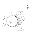
- Figure 3 represents a main cooling roll 10 associated with five support rollers 14 and four rollers of secondary cooling 16.
- the support roller or rollers 14 can have a multilayer structure, only the one and / or the outer layers to have the characteristics of flexibility and thermal capacity detailed above to achieve the invention.
- cooling roller 16 is replaceable by other means of cooling secondary, such as gas-jet quenching systems as long as these means form with part of the face external support rollers a sufficient area heat evacuation.
Landscapes
- Chemical & Material Sciences (AREA)
- Engineering & Computer Science (AREA)
- Materials Engineering (AREA)
- Thermal Sciences (AREA)
- Crystallography & Structural Chemistry (AREA)
- Mechanical Engineering (AREA)
- Physics & Mathematics (AREA)
- Metallurgy (AREA)
- Organic Chemistry (AREA)
- Heat Treatment Of Strip Materials And Filament Materials (AREA)
- Rolls And Other Rotary Bodies (AREA)
- Heat Treatments In General, Especially Conveying And Cooling (AREA)
- Extrusion Moulding Of Plastics Or The Like (AREA)
- Continuous Casting (AREA)
Priority Applications (11)
| Application Number | Priority Date | Filing Date | Title |
|---|---|---|---|
| EP03291389A EP1486573B1 (fr) | 2003-06-11 | 2003-06-11 | Procédé et installation de refroidissement d'une bande métallique en défilement |
| AT03291389T ATE312948T1 (de) | 2003-06-11 | 2003-06-11 | Verfahren und vorrichtung zur kühlung eines sich bewegenden metallischen bandes |
| DE60302777T DE60302777T2 (de) | 2003-06-11 | 2003-06-11 | Verfahren und Vorrichtung zur Kühlung eines sich bewegenden metallischen Bandes |
| ES03291389T ES2253645T3 (es) | 2003-06-11 | 2003-06-11 | Procedimiento e instalacion de refrigeracion de una banda metalica en movimiento. |
| JP2006516279A JP4676432B2 (ja) | 2003-06-11 | 2004-06-09 | 移動する金属ストリップを冷却するための方法およびプラント |
| PCT/FR2004/001441 WO2004111280A2 (fr) | 2003-06-11 | 2004-06-09 | Procede et installation de refroidissement d'une bande metallique en defilement |
| CA2528688A CA2528688C (fr) | 2003-06-11 | 2004-06-09 | Procede et installation de refroidissement d'une bande metallique en defilement |
| US10/560,175 US7527701B2 (en) | 2003-06-11 | 2004-06-09 | Method and plant for cooling a moving metal strip |
| CNB2004800159915A CN100424194C (zh) | 2003-06-11 | 2004-06-09 | 用于冷却移动的金属带材的方法和组件 |
| BRPI0411380-2A BRPI0411380B1 (pt) | 2003-06-11 | 2004-06-09 | Processo e instalação de resfriamento de uma tira metálica em movimento |
| RU2006100290/02A RU2336338C2 (ru) | 2003-06-11 | 2004-06-09 | Способ и установка для охлаждения металлической ленты при ее протягивании |
Applications Claiming Priority (1)
| Application Number | Priority Date | Filing Date | Title |
|---|---|---|---|
| EP03291389A EP1486573B1 (fr) | 2003-06-11 | 2003-06-11 | Procédé et installation de refroidissement d'une bande métallique en défilement |
Publications (2)
| Publication Number | Publication Date |
|---|---|
| EP1486573A1 EP1486573A1 (fr) | 2004-12-15 |
| EP1486573B1 true EP1486573B1 (fr) | 2005-12-14 |
Family
ID=33185988
Family Applications (1)
| Application Number | Title | Priority Date | Filing Date |
|---|---|---|---|
| EP03291389A Expired - Lifetime EP1486573B1 (fr) | 2003-06-11 | 2003-06-11 | Procédé et installation de refroidissement d'une bande métallique en défilement |
Country Status (11)
| Country | Link |
|---|---|
| US (1) | US7527701B2 (pt) |
| EP (1) | EP1486573B1 (pt) |
| JP (1) | JP4676432B2 (pt) |
| CN (1) | CN100424194C (pt) |
| AT (1) | ATE312948T1 (pt) |
| BR (1) | BRPI0411380B1 (pt) |
| CA (1) | CA2528688C (pt) |
| DE (1) | DE60302777T2 (pt) |
| ES (1) | ES2253645T3 (pt) |
| RU (1) | RU2336338C2 (pt) |
| WO (1) | WO2004111280A2 (pt) |
Families Citing this family (5)
| Publication number | Priority date | Publication date | Assignee | Title |
|---|---|---|---|---|
| EP2143504A1 (de) * | 2008-07-07 | 2010-01-13 | Siemens Aktiengesellschaft | Verfahren zum Kühlen eines zu einem Warmbandbund aufgehaspelten Warmbands, eine Vorrichtung zum Kühlen eines Warmbandbundes, eine Steuer- und/oder eine Regeleinrichtung und Metallband |
| JP2011042814A (ja) * | 2009-08-19 | 2011-03-03 | Chugai Ro Co Ltd | 金属ストリップの冷却装置及び冷却方法 |
| DE102012020622A1 (de) * | 2012-10-19 | 2014-04-24 | Maschinenfabrik Niehoff Gmbh & Co Kg | Vorrichtung zur Wärmeübertragung bei der Herstellung von langgestrecktem Stranggut |
| CN103358599A (zh) * | 2013-08-02 | 2013-10-23 | 常熟市沪虞港口机械有限公司 | 纸箱机械用瓦楞辊结构 |
| CN109746271B (zh) * | 2019-01-14 | 2020-04-10 | 中南大学 | 一种高性能铜箔的深冷叠轧制备方法 |
Family Cites Families (12)
| Publication number | Priority date | Publication date | Assignee | Title |
|---|---|---|---|---|
| JPS5743939A (en) * | 1980-08-29 | 1982-03-12 | Nippon Steel Corp | Structure for turning and conveying strip in continuously annealing furnace |
| JPS60255933A (ja) * | 1984-05-30 | 1985-12-17 | Nisshin Steel Co Ltd | 金属帯冷却装置 |
| JPS61243127A (ja) * | 1985-04-18 | 1986-10-29 | Nippon Steel Corp | 金属ストリツプの冷却方法 |
| JPH0830221B2 (ja) * | 1988-06-30 | 1996-03-27 | 川崎製鉄株式会社 | 金属ストリップの連続熱処理方法 |
| FR2651795B1 (fr) * | 1989-09-14 | 1993-10-08 | Sollac | Dispositif de refroidissement par contact de rouleaux pour la trempe en continu d'une bande d'acier prechauffee. |
| JPH03170619A (ja) * | 1989-11-30 | 1991-07-24 | Kawasaki Steel Corp | 連続焼鈍炉のロール冷却装置 |
| US5182074A (en) * | 1990-07-31 | 1993-01-26 | Nkk Corporation | Apparatus for continuously cooling metal strip |
| JPH079044B2 (ja) * | 1990-08-28 | 1995-02-01 | 日本鋼管株式会社 | 連続焼鈍炉におけるストリップ冷却装置 |
| EP0614992B1 (en) * | 1992-06-23 | 1999-04-21 | Nkk Corporation | Metal band cooling apparatus and cooling method therefor |
| AT407880B (de) * | 1997-09-22 | 2001-07-25 | Ebner Peter Dipl Ing | Anlage zur kontinuierlichen wärmebehandlung eines stahlbandes |
| JP2001323325A (ja) * | 2000-05-11 | 2001-11-22 | Nippon Steel Corp | 金属帯板の冷却装置および冷却方法 |
| RU2201461C1 (ru) * | 2002-04-16 | 2003-03-27 | Урцев Владимир Николаевич | Линия для охлаждения рулонной полосы после отжига |
-
2003
- 2003-06-11 ES ES03291389T patent/ES2253645T3/es not_active Expired - Lifetime
- 2003-06-11 EP EP03291389A patent/EP1486573B1/fr not_active Expired - Lifetime
- 2003-06-11 AT AT03291389T patent/ATE312948T1/de active
- 2003-06-11 DE DE60302777T patent/DE60302777T2/de not_active Expired - Lifetime
-
2004
- 2004-06-09 CA CA2528688A patent/CA2528688C/fr not_active Expired - Lifetime
- 2004-06-09 US US10/560,175 patent/US7527701B2/en not_active Expired - Lifetime
- 2004-06-09 CN CNB2004800159915A patent/CN100424194C/zh not_active Expired - Lifetime
- 2004-06-09 JP JP2006516279A patent/JP4676432B2/ja not_active Expired - Lifetime
- 2004-06-09 RU RU2006100290/02A patent/RU2336338C2/ru active
- 2004-06-09 WO PCT/FR2004/001441 patent/WO2004111280A2/fr not_active Ceased
- 2004-06-09 BR BRPI0411380-2A patent/BRPI0411380B1/pt not_active IP Right Cessation
Also Published As
| Publication number | Publication date |
|---|---|
| JP4676432B2 (ja) | 2011-04-27 |
| CA2528688A1 (fr) | 2004-12-23 |
| US20060254682A1 (en) | 2006-11-16 |
| BRPI0411380B1 (pt) | 2014-08-12 |
| US7527701B2 (en) | 2009-05-05 |
| CN1802444A (zh) | 2006-07-12 |
| JP2006527307A (ja) | 2006-11-30 |
| WO2004111280A3 (fr) | 2005-02-17 |
| ATE312948T1 (de) | 2005-12-15 |
| CA2528688C (fr) | 2012-03-06 |
| RU2006100290A (ru) | 2006-06-10 |
| CN100424194C (zh) | 2008-10-08 |
| RU2336338C2 (ru) | 2008-10-20 |
| DE60302777D1 (de) | 2006-01-19 |
| DE60302777T2 (de) | 2006-07-06 |
| EP1486573A1 (fr) | 2004-12-15 |
| ES2253645T3 (es) | 2006-06-01 |
| BRPI0411380A (pt) | 2006-08-01 |
| WO2004111280A2 (fr) | 2004-12-23 |
Similar Documents
| Publication | Publication Date | Title |
|---|---|---|
| EP2454081B1 (fr) | Machine d'application de fibres comprenant un rouleau de compactage souple avec systeme de regulation thermique | |
| FR2948059A1 (fr) | Machine d'application de fibres avec rouleau de compactage transparent au rayonnement du systeme de chauffage | |
| CA3015217C (fr) | Dispositif d'application de materiau abradable sur une surface d'un carter de turbomachine | |
| EP2391459B1 (fr) | Methode et dispositif d'arrosage d'une installation de laminage | |
| FR2793239A1 (fr) | Procede de fabrication de verre flotte, dispositif de mise en oeuvre et produits obtenus | |
| EP1049813B1 (fr) | Reacteur et procede pour depot chimique en phase vapeur | |
| CA2528688C (fr) | Procede et installation de refroidissement d'une bande metallique en defilement | |
| EP1337681A1 (fr) | Installation de revetement au trempe d'une bande metallique | |
| EP0345147A1 (fr) | Rouleau pour la manutention de produits sidérurgiques se déplaçant à l'intérieur d'un four | |
| EP0404677B1 (fr) | Dispositif pour la trempe par contact de vitrages | |
| FR2500143A1 (fr) | Echangeurs de chaleur a structure capillaire, pour machines frigorifiques et/ou pompes a chaleur | |
| EP4090511B1 (fr) | Machine d'extrusion utilisant une chaîne de rouleaux articulée pour engager et guider un profilé extrudé contre un rouleau refroidisseur | |
| EP1377529B1 (fr) | Procede et dispositif de chauffage de feuilles de verre dans un four | |
| EP0005389B1 (fr) | Installation de bombage et de trempe de feuilles de verre | |
| EP0059675B1 (fr) | Dispositif de refroidissement rapide de tubes métalliques | |
| FR2924975A1 (fr) | Dispositif d'etirage longitudinal de films en matiere synthetique | |
| EP1608499B1 (fr) | Dispositif d'etirage longitudinal de films | |
| FR2745510A1 (fr) | Cylindre de coulee d'une installation de coulee continue sur un ou entre deux cylindres | |
| KR101482351B1 (ko) | 워크롤의 와이퍼 장치 | |
| BE1004684A6 (fr) | Enceinte cylindrique de grand diametre destinee a recevoir des organes devant etre refroidis. | |
| FR3058653A1 (fr) | Machine de cintrage comportant un mandrin gonflable et procede de cintrage | |
| EP0418166A1 (fr) | Dispositif de refroidissement par contact de rouleaux pour la trempe en continu d'une bande d'acier préchauffée | |
| FR2882293A1 (fr) | Rouleau pour la mise en oeuvre de films en matiere plastique | |
| FR2504042A1 (fr) | Machine pour souder sous atmosphere gazeuse des elements longiformes en particulier des tubes en titane | |
| CH647172A5 (fr) | Machine de coulee continue de metal en fusion. |
Legal Events
| Date | Code | Title | Description |
|---|---|---|---|
| PUAI | Public reference made under article 153(3) epc to a published international application that has entered the european phase |
Free format text: ORIGINAL CODE: 0009012 |
|
| AK | Designated contracting states |
Kind code of ref document: A1 Designated state(s): AT BE BG CH CY CZ DE DK EE ES FI FR GB GR HU IE IT LI LU MC NL PT RO SE SI SK TR |
|
| AX | Request for extension of the european patent |
Extension state: AL LT LV MK |
|
| 17P | Request for examination filed |
Effective date: 20041210 |
|
| GRAP | Despatch of communication of intention to grant a patent |
Free format text: ORIGINAL CODE: EPIDOSNIGR1 |
|
| AKX | Designation fees paid |
Designated state(s): AT BE BG CH CY CZ DE DK EE ES FI FR GB GR HU IE IT LI LU MC NL PT RO SE SI SK TR |
|
| GRAS | Grant fee paid |
Free format text: ORIGINAL CODE: EPIDOSNIGR3 |
|
| GRAA | (expected) grant |
Free format text: ORIGINAL CODE: 0009210 |
|
| AK | Designated contracting states |
Kind code of ref document: B1 Designated state(s): AT BE BG CH CY CZ DE DK EE ES FI FR GB GR HU IE IT LI LU MC NL PT RO SE SI SK TR |
|
| PG25 | Lapsed in a contracting state [announced via postgrant information from national office to epo] |
Ref country code: SI Free format text: LAPSE BECAUSE OF FAILURE TO SUBMIT A TRANSLATION OF THE DESCRIPTION OR TO PAY THE FEE WITHIN THE PRESCRIBED TIME-LIMIT Effective date: 20051214 |
|
| REG | Reference to a national code |
Ref country code: GB Ref legal event code: FG4D Free format text: NOT ENGLISH |
|
| REG | Reference to a national code |
Ref country code: CH Ref legal event code: EP |
|
| REG | Reference to a national code |
Ref country code: SE Ref legal event code: TRGR |
|
| GBT | Gb: translation of ep patent filed (gb section 77(6)(a)/1977) |
Effective date: 20051214 |
|
| REG | Reference to a national code |
Ref country code: IE Ref legal event code: FG4D Free format text: LANGUAGE OF EP DOCUMENT: FRENCH |
|
| REF | Corresponds to: |
Ref document number: 60302777 Country of ref document: DE Date of ref document: 20060119 Kind code of ref document: P |
|
| REG | Reference to a national code |
Ref country code: RO Ref legal event code: EPE |
|
| PG25 | Lapsed in a contracting state [announced via postgrant information from national office to epo] |
Ref country code: DK Free format text: LAPSE BECAUSE OF FAILURE TO SUBMIT A TRANSLATION OF THE DESCRIPTION OR TO PAY THE FEE WITHIN THE PRESCRIBED TIME-LIMIT Effective date: 20060314 Ref country code: BG Free format text: LAPSE BECAUSE OF FAILURE TO SUBMIT A TRANSLATION OF THE DESCRIPTION OR TO PAY THE FEE WITHIN THE PRESCRIBED TIME-LIMIT Effective date: 20060314 |
|
| REG | Reference to a national code |
Ref country code: GR Ref legal event code: EP Ref document number: 20060400456 Country of ref document: GR |
|
| PG25 | Lapsed in a contracting state [announced via postgrant information from national office to epo] |
Ref country code: PT Free format text: LAPSE BECAUSE OF FAILURE TO SUBMIT A TRANSLATION OF THE DESCRIPTION OR TO PAY THE FEE WITHIN THE PRESCRIBED TIME-LIMIT Effective date: 20060515 |
|
| REG | Reference to a national code |
Ref country code: ES Ref legal event code: FG2A Ref document number: 2253645 Country of ref document: ES Kind code of ref document: T3 |
|
| PG25 | Lapsed in a contracting state [announced via postgrant information from national office to epo] |
Ref country code: HU Free format text: LAPSE BECAUSE OF FAILURE TO SUBMIT A TRANSLATION OF THE DESCRIPTION OR TO PAY THE FEE WITHIN THE PRESCRIBED TIME-LIMIT Effective date: 20060615 |
|
| PG25 | Lapsed in a contracting state [announced via postgrant information from national office to epo] |
Ref country code: MC Free format text: LAPSE BECAUSE OF NON-PAYMENT OF DUE FEES Effective date: 20060630 |
|
| RAP2 | Party data changed (patent owner data changed or rights of a patent transferred) |
Owner name: ARCELOR FRANCE |
|
| PLBE | No opposition filed within time limit |
Free format text: ORIGINAL CODE: 0009261 |
|
| STAA | Information on the status of an ep patent application or granted ep patent |
Free format text: STATUS: NO OPPOSITION FILED WITHIN TIME LIMIT |
|
| NLT2 | Nl: modifications (of names), taken from the european patent patent bulletin |
Owner name: ARCELOR FRANCE Effective date: 20060823 |
|
| 26N | No opposition filed |
Effective date: 20060915 |
|
| REG | Reference to a national code |
Ref country code: CH Ref legal event code: PL |
|
| PG25 | Lapsed in a contracting state [announced via postgrant information from national office to epo] |
Ref country code: LI Free format text: LAPSE BECAUSE OF NON-PAYMENT OF DUE FEES Effective date: 20070630 Ref country code: CH Free format text: LAPSE BECAUSE OF NON-PAYMENT OF DUE FEES Effective date: 20070630 |
|
| PG25 | Lapsed in a contracting state [announced via postgrant information from national office to epo] |
Ref country code: EE Free format text: LAPSE BECAUSE OF FAILURE TO SUBMIT A TRANSLATION OF THE DESCRIPTION OR TO PAY THE FEE WITHIN THE PRESCRIBED TIME-LIMIT Effective date: 20051214 |
|
| PG25 | Lapsed in a contracting state [announced via postgrant information from national office to epo] |
Ref country code: LU Free format text: LAPSE BECAUSE OF NON-PAYMENT OF DUE FEES Effective date: 20060611 |
|
| PG25 | Lapsed in a contracting state [announced via postgrant information from national office to epo] |
Ref country code: CY Free format text: LAPSE BECAUSE OF FAILURE TO SUBMIT A TRANSLATION OF THE DESCRIPTION OR TO PAY THE FEE WITHIN THE PRESCRIBED TIME-LIMIT Effective date: 20051214 |
|
| REG | Reference to a national code |
Ref country code: FR Ref legal event code: PLFP Year of fee payment: 14 |
|
| REG | Reference to a national code |
Ref country code: FR Ref legal event code: PLFP Year of fee payment: 15 |
|
| REG | Reference to a national code |
Ref country code: FR Ref legal event code: PLFP Year of fee payment: 16 |
|
| PGFP | Annual fee paid to national office [announced via postgrant information from national office to epo] |
Ref country code: NL Payment date: 20220523 Year of fee payment: 20 |
|
| PGFP | Annual fee paid to national office [announced via postgrant information from national office to epo] |
Ref country code: SK Payment date: 20220523 Year of fee payment: 20 Ref country code: SE Payment date: 20220519 Year of fee payment: 20 Ref country code: RO Payment date: 20220606 Year of fee payment: 20 Ref country code: IT Payment date: 20220518 Year of fee payment: 20 Ref country code: IE Payment date: 20220519 Year of fee payment: 20 Ref country code: GB Payment date: 20220519 Year of fee payment: 20 Ref country code: FR Payment date: 20220519 Year of fee payment: 20 Ref country code: DE Payment date: 20220518 Year of fee payment: 20 Ref country code: CZ Payment date: 20220524 Year of fee payment: 20 |
|
| PGFP | Annual fee paid to national office [announced via postgrant information from national office to epo] |
Ref country code: TR Payment date: 20220524 Year of fee payment: 20 Ref country code: GR Payment date: 20220519 Year of fee payment: 20 Ref country code: FI Payment date: 20220513 Year of fee payment: 20 Ref country code: BE Payment date: 20220523 Year of fee payment: 20 Ref country code: AT Payment date: 20220519 Year of fee payment: 20 |
|
| PGFP | Annual fee paid to national office [announced via postgrant information from national office to epo] |
Ref country code: ES Payment date: 20220701 Year of fee payment: 20 |
|
| REG | Reference to a national code |
Ref country code: DE Ref legal event code: R071 Ref document number: 60302777 Country of ref document: DE |
|
| REG | Reference to a national code |
Ref country code: NL Ref legal event code: MK Effective date: 20230610 |
|
| REG | Reference to a national code |
Ref country code: ES Ref legal event code: FD2A Effective date: 20230626 |
|
| REG | Reference to a national code |
Ref country code: BE Ref legal event code: MK Effective date: 20230611 |
|
| REG | Reference to a national code |
Ref country code: SK Ref legal event code: MK4A Ref document number: E 355 Country of ref document: SK Expiry date: 20230611 |
|
| REG | Reference to a national code |
Ref country code: GB Ref legal event code: PE20 Expiry date: 20230610 |
|
| REG | Reference to a national code |
Ref country code: AT Ref legal event code: MK07 Ref document number: 312948 Country of ref document: AT Kind code of ref document: T Effective date: 20230611 |
|
| PG25 | Lapsed in a contracting state [announced via postgrant information from national office to epo] |
Ref country code: ES Free format text: LAPSE BECAUSE OF EXPIRATION OF PROTECTION Effective date: 20230612 Ref country code: CZ Free format text: LAPSE BECAUSE OF EXPIRATION OF PROTECTION Effective date: 20230611 |
|
| REG | Reference to a national code |
Ref country code: SE Ref legal event code: EUG |
|
| REG | Reference to a national code |
Ref country code: IE Ref legal event code: MK9A |
|
| PG25 | Lapsed in a contracting state [announced via postgrant information from national office to epo] |
Ref country code: SK Free format text: LAPSE BECAUSE OF EXPIRATION OF PROTECTION Effective date: 20230611 |
|
| PG25 | Lapsed in a contracting state [announced via postgrant information from national office to epo] |
Ref country code: IE Free format text: LAPSE BECAUSE OF EXPIRATION OF PROTECTION Effective date: 20230611 Ref country code: GB Free format text: LAPSE BECAUSE OF EXPIRATION OF PROTECTION Effective date: 20230610 |