EP1679162B1 - Vorrichtung zum Schneiden von bandförmigem, thermischem Bildmaterial - Google Patents
Vorrichtung zum Schneiden von bandförmigem, thermischem Bildmaterial Download PDFInfo
- Publication number
- EP1679162B1 EP1679162B1 EP20060003987 EP06003987A EP1679162B1 EP 1679162 B1 EP1679162 B1 EP 1679162B1 EP 20060003987 EP20060003987 EP 20060003987 EP 06003987 A EP06003987 A EP 06003987A EP 1679162 B1 EP1679162 B1 EP 1679162B1
- Authority
- EP
- European Patent Office
- Prior art keywords
- thermal imaging
- imaging material
- layer
- cutting
- range
- Prior art date
- Legal status (The legal status is an assumption and is not a legal conclusion. Google has not performed a legal analysis and makes no representation as to the accuracy of the status listed.)
- Expired - Lifetime
Links
- 238000005520 cutting process Methods 0.000 title claims abstract description 101
- 239000000463 material Substances 0.000 title claims description 233
- 238000001931 thermography Methods 0.000 title claims description 215
- 238000012546 transfer Methods 0.000 claims abstract description 19
- 239000000839 emulsion Substances 0.000 claims description 87
- 238000010438 heat treatment Methods 0.000 abstract description 57
- 238000010276 construction Methods 0.000 abstract description 12
- 230000009477 glass transition Effects 0.000 abstract description 6
- 238000001816 cooling Methods 0.000 abstract description 3
- 239000010410 layer Substances 0.000 description 199
- -1 polyethylene terephthalate Polymers 0.000 description 99
- 229910052709 silver Inorganic materials 0.000 description 96
- 239000004332 silver Substances 0.000 description 96
- 238000000034 method Methods 0.000 description 83
- 239000002245 particle Substances 0.000 description 76
- XLYOFNOQVPJJNP-UHFFFAOYSA-N water Substances O XLYOFNOQVPJJNP-UHFFFAOYSA-N 0.000 description 71
- 239000007788 liquid Substances 0.000 description 63
- GGCZERPQGJTIQP-UHFFFAOYSA-N sodium;9,10-dioxoanthracene-2-sulfonic acid Chemical compound [Na+].C1=CC=C2C(=O)C3=CC(S(=O)(=O)O)=CC=C3C(=O)C2=C1 GGCZERPQGJTIQP-UHFFFAOYSA-N 0.000 description 58
- 239000006185 dispersion Substances 0.000 description 56
- 239000004816 latex Substances 0.000 description 52
- 229920000126 latex Polymers 0.000 description 52
- OKKJLVBELUTLKV-UHFFFAOYSA-N Methanol Chemical compound OC OKKJLVBELUTLKV-UHFFFAOYSA-N 0.000 description 45
- 229920000642 polymer Polymers 0.000 description 41
- 150000001875 compounds Chemical class 0.000 description 38
- 239000000243 solution Substances 0.000 description 36
- 238000002360 preparation method Methods 0.000 description 31
- BQCADISMDOOEFD-UHFFFAOYSA-N Silver Chemical compound [Ag] BQCADISMDOOEFD-UHFFFAOYSA-N 0.000 description 29
- 239000007864 aqueous solution Substances 0.000 description 28
- 230000001235 sensitizing effect Effects 0.000 description 25
- 239000003638 chemical reducing agent Substances 0.000 description 24
- 239000000975 dye Substances 0.000 description 22
- 239000000126 substance Substances 0.000 description 22
- 239000000049 pigment Substances 0.000 description 21
- 238000011156 evaluation Methods 0.000 description 20
- 229920002451 polyvinyl alcohol Polymers 0.000 description 20
- 239000007787 solid Substances 0.000 description 18
- PPBRXRYQALVLMV-UHFFFAOYSA-N Styrene Chemical compound C=CC1=CC=CC=C1 PPBRXRYQALVLMV-UHFFFAOYSA-N 0.000 description 17
- 239000004372 Polyvinyl alcohol Substances 0.000 description 16
- 229940068984 polyvinyl alcohol Drugs 0.000 description 16
- 235000019422 polyvinyl alcohol Nutrition 0.000 description 16
- 239000002904 solvent Substances 0.000 description 16
- 108010010803 Gelatin Proteins 0.000 description 15
- 239000002585 base Substances 0.000 description 15
- 239000011230 binding agent Substances 0.000 description 15
- 229920000159 gelatin Polymers 0.000 description 15
- 235000019322 gelatine Nutrition 0.000 description 15
- 235000011852 gelatine desserts Nutrition 0.000 description 15
- 150000003839 salts Chemical class 0.000 description 15
- 238000007792 addition Methods 0.000 description 14
- 239000008273 gelatin Substances 0.000 description 14
- 229940014259 gelatin Drugs 0.000 description 14
- 239000000203 mixture Substances 0.000 description 14
- 229920001577 copolymer Polymers 0.000 description 13
- 239000012153 distilled water Substances 0.000 description 13
- 238000000926 separation method Methods 0.000 description 13
- 238000000576 coating method Methods 0.000 description 12
- 238000002156 mixing Methods 0.000 description 12
- HEMHJVSKTPXQMS-UHFFFAOYSA-M Sodium hydroxide Chemical compound [OH-].[Na+] HEMHJVSKTPXQMS-UHFFFAOYSA-M 0.000 description 11
- 239000011248 coating agent Substances 0.000 description 11
- 239000004576 sand Substances 0.000 description 11
- 238000012360 testing method Methods 0.000 description 11
- VVQNEPGJFQJSBK-UHFFFAOYSA-N Methyl methacrylate Chemical compound COC(=O)C(C)=C VVQNEPGJFQJSBK-UHFFFAOYSA-N 0.000 description 10
- QAOWNCQODCNURD-UHFFFAOYSA-N Sulfuric acid Chemical compound OS(O)(=O)=O QAOWNCQODCNURD-UHFFFAOYSA-N 0.000 description 10
- XNGIFLGASWRNHJ-UHFFFAOYSA-N phthalic acid Chemical compound OC(=O)C1=CC=CC=C1C(O)=O XNGIFLGASWRNHJ-UHFFFAOYSA-N 0.000 description 10
- 239000002002 slurry Substances 0.000 description 10
- KAKZBPTYRLMSJV-UHFFFAOYSA-N Butadiene Chemical compound C=CC=C KAKZBPTYRLMSJV-UHFFFAOYSA-N 0.000 description 9
- XEKOWRVHYACXOJ-UHFFFAOYSA-N Ethyl acetate Chemical compound CCOC(C)=O XEKOWRVHYACXOJ-UHFFFAOYSA-N 0.000 description 9
- 239000003795 chemical substances by application Substances 0.000 description 9
- 238000011033 desalting Methods 0.000 description 9
- 239000010419 fine particle Substances 0.000 description 9
- 239000002243 precursor Substances 0.000 description 9
- 229920005989 resin Polymers 0.000 description 9
- 239000011347 resin Substances 0.000 description 9
- 229920003048 styrene butadiene rubber Polymers 0.000 description 9
- IOLCXVTUBQKXJR-UHFFFAOYSA-M potassium bromide Chemical compound [K+].[Br-] IOLCXVTUBQKXJR-UHFFFAOYSA-M 0.000 description 8
- 230000037452 priming Effects 0.000 description 8
- SQGYOTSLMSWVJD-UHFFFAOYSA-N silver(1+) nitrate Chemical compound [Ag+].[O-]N(=O)=O SQGYOTSLMSWVJD-UHFFFAOYSA-N 0.000 description 8
- NBIIXXVUZAFLBC-UHFFFAOYSA-N Phosphoric acid Chemical compound OP(O)(O)=O NBIIXXVUZAFLBC-UHFFFAOYSA-N 0.000 description 7
- 239000004743 Polypropylene Substances 0.000 description 7
- 206010070834 Sensitisation Diseases 0.000 description 7
- 239000002253 acid Substances 0.000 description 7
- 238000009826 distribution Methods 0.000 description 7
- 239000000428 dust Substances 0.000 description 7
- 238000002474 experimental method Methods 0.000 description 7
- 239000012530 fluid Substances 0.000 description 7
- 230000003287 optical effect Effects 0.000 description 7
- LFSXCDWNBUNEEM-UHFFFAOYSA-N phthalazine Chemical group C1=NN=CC2=CC=CC=C21 LFSXCDWNBUNEEM-UHFFFAOYSA-N 0.000 description 7
- 229920001155 polypropylene Polymers 0.000 description 7
- 239000011148 porous material Substances 0.000 description 7
- 230000008313 sensitization Effects 0.000 description 7
- 239000002344 surface layer Substances 0.000 description 7
- 229910052714 tellurium Inorganic materials 0.000 description 7
- PORWMNRCUJJQNO-UHFFFAOYSA-N tellurium atom Chemical compound [Te] PORWMNRCUJJQNO-UHFFFAOYSA-N 0.000 description 7
- AWDBHOZBRXWRKS-UHFFFAOYSA-N tetrapotassium;iron(6+);hexacyanide Chemical compound [K+].[K+].[K+].[K+].[Fe+6].N#[C-].N#[C-].N#[C-].N#[C-].N#[C-].N#[C-] AWDBHOZBRXWRKS-UHFFFAOYSA-N 0.000 description 7
- 238000011144 upstream manufacturing Methods 0.000 description 7
- KAESVJOAVNADME-UHFFFAOYSA-N Pyrrole Chemical class C=1C=CNC=1 KAESVJOAVNADME-UHFFFAOYSA-N 0.000 description 6
- DKGAVHZHDRPRBM-UHFFFAOYSA-N Tert-Butanol Chemical compound CC(C)(C)O DKGAVHZHDRPRBM-UHFFFAOYSA-N 0.000 description 6
- 238000010521 absorption reaction Methods 0.000 description 6
- 230000032683 aging Effects 0.000 description 6
- 239000011324 bead Substances 0.000 description 6
- 230000015572 biosynthetic process Effects 0.000 description 6
- 238000007664 blowing Methods 0.000 description 6
- 229910052799 carbon Inorganic materials 0.000 description 6
- 238000010586 diagram Methods 0.000 description 6
- 230000000694 effects Effects 0.000 description 6
- 238000003384 imaging method Methods 0.000 description 6
- 239000000178 monomer Substances 0.000 description 6
- 239000011241 protective layer Substances 0.000 description 6
- 230000035945 sensitivity Effects 0.000 description 6
- 238000010008 shearing Methods 0.000 description 6
- 239000004094 surface-active agent Substances 0.000 description 6
- MYRTYDVEIRVNKP-UHFFFAOYSA-N 1,2-Divinylbenzene Chemical compound C=CC1=CC=CC=C1C=C MYRTYDVEIRVNKP-UHFFFAOYSA-N 0.000 description 5
- QGZKDVFQNNGYKY-UHFFFAOYSA-N Ammonia Chemical compound N QGZKDVFQNNGYKY-UHFFFAOYSA-N 0.000 description 5
- WOBHKFSMXKNTIM-UHFFFAOYSA-N Hydroxyethyl methacrylate Chemical compound CC(=C)C(=O)OCCO WOBHKFSMXKNTIM-UHFFFAOYSA-N 0.000 description 5
- KFZMGEQAYNKOFK-UHFFFAOYSA-N Isopropanol Chemical compound CC(C)O KFZMGEQAYNKOFK-UHFFFAOYSA-N 0.000 description 5
- 239000002174 Styrene-butadiene Substances 0.000 description 5
- QCWXUUIWCKQGHC-UHFFFAOYSA-N Zirconium Chemical compound [Zr] QCWXUUIWCKQGHC-UHFFFAOYSA-N 0.000 description 5
- 238000006243 chemical reaction Methods 0.000 description 5
- 238000009472 formulation Methods 0.000 description 5
- 150000004820 halides Chemical class 0.000 description 5
- 229910052741 iridium Inorganic materials 0.000 description 5
- GKOZUEZYRPOHIO-UHFFFAOYSA-N iridium atom Chemical compound [Ir] GKOZUEZYRPOHIO-UHFFFAOYSA-N 0.000 description 5
- 150000002504 iridium compounds Chemical class 0.000 description 5
- 230000007246 mechanism Effects 0.000 description 5
- 229910052751 metal Inorganic materials 0.000 description 5
- 239000002184 metal Substances 0.000 description 5
- 239000003960 organic solvent Substances 0.000 description 5
- 229920000139 polyethylene terephthalate Polymers 0.000 description 5
- 239000005020 polyethylene terephthalate Substances 0.000 description 5
- 230000001681 protective effect Effects 0.000 description 5
- 150000003378 silver Chemical class 0.000 description 5
- ADZWSOLPGZMUMY-UHFFFAOYSA-M silver bromide Chemical compound [Ag]Br ADZWSOLPGZMUMY-UHFFFAOYSA-M 0.000 description 5
- 229910052726 zirconium Inorganic materials 0.000 description 5
- KANAPVJGZDNSCZ-UHFFFAOYSA-N 1,2-benzothiazole 1-oxide Chemical compound C1=CC=C2S(=O)N=CC2=C1 KANAPVJGZDNSCZ-UHFFFAOYSA-N 0.000 description 4
- ZGOQRUPIKZGTLQ-UHFFFAOYSA-N 1,2-benzothiazole 1-oxide;sodium Chemical compound [Na].C1=CC=C2S(=O)N=CC2=C1 ZGOQRUPIKZGTLQ-UHFFFAOYSA-N 0.000 description 4
- SMZOUWXMTYCWNB-UHFFFAOYSA-N 2-(2-methoxy-5-methylphenyl)ethanamine Chemical compound COC1=CC=C(C)C=C1CCN SMZOUWXMTYCWNB-UHFFFAOYSA-N 0.000 description 4
- NIXOWILDQLNWCW-UHFFFAOYSA-N 2-Propenoic acid Natural products OC(=O)C=C NIXOWILDQLNWCW-UHFFFAOYSA-N 0.000 description 4
- ZNQVEEAIQZEUHB-UHFFFAOYSA-N 2-ethoxyethanol Chemical group CCOCCO ZNQVEEAIQZEUHB-UHFFFAOYSA-N 0.000 description 4
- CWJJAFQCTXFSTA-UHFFFAOYSA-N 4-methylphthalic acid Chemical compound CC1=CC=C(C(O)=O)C(C(O)=O)=C1 CWJJAFQCTXFSTA-UHFFFAOYSA-N 0.000 description 4
- RTZKZFJDLAIYFH-UHFFFAOYSA-N Diethyl ether Chemical compound CCOCC RTZKZFJDLAIYFH-UHFFFAOYSA-N 0.000 description 4
- LFQSCWFLJHTTHZ-UHFFFAOYSA-N Ethanol Chemical compound CCO LFQSCWFLJHTTHZ-UHFFFAOYSA-N 0.000 description 4
- IMROMDMJAWUWLK-UHFFFAOYSA-N Ethenol Chemical compound OC=C IMROMDMJAWUWLK-UHFFFAOYSA-N 0.000 description 4
- XYFCBTPGUUZFHI-UHFFFAOYSA-N Phosphine Natural products P XYFCBTPGUUZFHI-UHFFFAOYSA-N 0.000 description 4
- 235000010724 Wisteria floribunda Nutrition 0.000 description 4
- CQEYYJKEWSMYFG-UHFFFAOYSA-N butyl acrylate Chemical compound CCCCOC(=O)C=C CQEYYJKEWSMYFG-UHFFFAOYSA-N 0.000 description 4
- 230000008859 change Effects 0.000 description 4
- 238000007334 copolymerization reaction Methods 0.000 description 4
- 239000013078 crystal Substances 0.000 description 4
- KZTYYGOKRVBIMI-UHFFFAOYSA-N diphenyl sulfone Chemical compound C=1C=CC=CC=1S(=O)(=O)C1=CC=CC=C1 KZTYYGOKRVBIMI-UHFFFAOYSA-N 0.000 description 4
- 150000002500 ions Chemical class 0.000 description 4
- BDAGIHXWWSANSR-UHFFFAOYSA-N methanoic acid Natural products OC=O BDAGIHXWWSANSR-UHFFFAOYSA-N 0.000 description 4
- 150000007524 organic acids Chemical class 0.000 description 4
- 229910000073 phosphorus hydride Inorganic materials 0.000 description 4
- 150000003021 phthalic acid derivatives Chemical class 0.000 description 4
- 239000004065 semiconductor Substances 0.000 description 4
- 229910001961 silver nitrate Inorganic materials 0.000 description 4
- 238000007767 slide coating Methods 0.000 description 4
- 230000003068 static effect Effects 0.000 description 4
- 238000000108 ultra-filtration Methods 0.000 description 4
- 229920002818 (Hydroxyethyl)methacrylate Polymers 0.000 description 3
- OEPOKWHJYJXUGD-UHFFFAOYSA-N 2-(3-phenylmethoxyphenyl)-1,3-thiazole-4-carbaldehyde Chemical compound O=CC1=CSC(C=2C=C(OCC=3C=CC=CC=3)C=CC=2)=N1 OEPOKWHJYJXUGD-UHFFFAOYSA-N 0.000 description 3
- TUQAKXMNDMTCFO-UHFFFAOYSA-N 3-heptyl-4-phenyl-1h-1,2,4-triazole-5-thione Chemical compound CCCCCCCC1=NNC(=S)N1C1=CC=CC=C1 TUQAKXMNDMTCFO-UHFFFAOYSA-N 0.000 description 3
- OVBJAABCEPSUNB-UHFFFAOYSA-N 6-propan-2-ylphthalazine Chemical class C1=NN=CC2=CC(C(C)C)=CC=C21 OVBJAABCEPSUNB-UHFFFAOYSA-N 0.000 description 3
- 229920002126 Acrylic acid copolymer Polymers 0.000 description 3
- LYCAIKOWRPUZTN-UHFFFAOYSA-N Ethylene glycol Chemical compound OCCO LYCAIKOWRPUZTN-UHFFFAOYSA-N 0.000 description 3
- IAYPIBMASNFSPL-UHFFFAOYSA-N Ethylene oxide Chemical compound C1CO1 IAYPIBMASNFSPL-UHFFFAOYSA-N 0.000 description 3
- 239000002202 Polyethylene glycol Substances 0.000 description 3
- BUGBHKTXTAQXES-UHFFFAOYSA-N Selenium Chemical compound [Se] BUGBHKTXTAQXES-UHFFFAOYSA-N 0.000 description 3
- NINIDFKCEFEMDL-UHFFFAOYSA-N Sulfur Chemical compound [S] NINIDFKCEFEMDL-UHFFFAOYSA-N 0.000 description 3
- BZHJMEDXRYGGRV-UHFFFAOYSA-N Vinyl chloride Chemical compound ClC=C BZHJMEDXRYGGRV-UHFFFAOYSA-N 0.000 description 3
- 230000009471 action Effects 0.000 description 3
- XSCHRSMBECNVNS-UHFFFAOYSA-N benzopyrazine Natural products N1=CC=NC2=CC=CC=C21 XSCHRSMBECNVNS-UHFFFAOYSA-N 0.000 description 3
- 239000000084 colloidal system Substances 0.000 description 3
- 239000003086 colorant Substances 0.000 description 3
- 230000002950 deficient Effects 0.000 description 3
- 238000011161 development Methods 0.000 description 3
- 230000018109 developmental process Effects 0.000 description 3
- UKMSUNONTOPOIO-UHFFFAOYSA-N docosanoic acid Chemical compound CCCCCCCCCCCCCCCCCCCCCC(O)=O UKMSUNONTOPOIO-UHFFFAOYSA-N 0.000 description 3
- 238000007765 extrusion coating Methods 0.000 description 3
- 238000001914 filtration Methods 0.000 description 3
- 229910052736 halogen Inorganic materials 0.000 description 3
- 150000002367 halogens Chemical class 0.000 description 3
- 230000000887 hydrating effect Effects 0.000 description 3
- 239000006224 matting agent Substances 0.000 description 3
- PNJWIWWMYCMZRO-UHFFFAOYSA-N pent‐4‐en‐2‐one Natural products CC(=O)CC=C PNJWIWWMYCMZRO-UHFFFAOYSA-N 0.000 description 3
- 235000011007 phosphoric acid Nutrition 0.000 description 3
- IJAPPYDYQCXOEF-UHFFFAOYSA-N phthalazin-1(2H)-one Chemical compound C1=CC=C2C(=O)NN=CC2=C1 IJAPPYDYQCXOEF-UHFFFAOYSA-N 0.000 description 3
- 229920003229 poly(methyl methacrylate) Polymers 0.000 description 3
- 229920000728 polyester Polymers 0.000 description 3
- 229920001223 polyethylene glycol Polymers 0.000 description 3
- 238000006116 polymerization reaction Methods 0.000 description 3
- 239000004926 polymethyl methacrylate Substances 0.000 description 3
- 239000000523 sample Substances 0.000 description 3
- 238000004062 sedimentation Methods 0.000 description 3
- 229910052711 selenium Inorganic materials 0.000 description 3
- 239000011669 selenium Substances 0.000 description 3
- AQRYNYUOKMNDDV-UHFFFAOYSA-M silver behenate Chemical compound [Ag+].CCCCCCCCCCCCCCCCCCCCCC([O-])=O AQRYNYUOKMNDDV-UHFFFAOYSA-M 0.000 description 3
- CVYDEWKUJFCYJO-UHFFFAOYSA-M sodium;docosanoate Chemical compound [Na+].CCCCCCCCCCCCCCCCCCCCCC([O-])=O CVYDEWKUJFCYJO-UHFFFAOYSA-M 0.000 description 3
- 239000003381 stabilizer Substances 0.000 description 3
- 229910052717 sulfur Inorganic materials 0.000 description 3
- 239000011593 sulfur Substances 0.000 description 3
- DLYUQMMRRRQYAE-UHFFFAOYSA-N tetraphosphorus decaoxide Chemical compound O1P(O2)(=O)OP3(=O)OP1(=O)OP2(=O)O3 DLYUQMMRRRQYAE-UHFFFAOYSA-N 0.000 description 3
- QPFMBZIOSGYJDE-UHFFFAOYSA-N 1,1,2,2-tetrachloroethane Chemical compound ClC(Cl)C(Cl)Cl QPFMBZIOSGYJDE-UHFFFAOYSA-N 0.000 description 2
- JAHNSTQSQJOJLO-UHFFFAOYSA-N 2-(3-fluorophenyl)-1h-imidazole Chemical compound FC1=CC=CC(C=2NC=CN=2)=C1 JAHNSTQSQJOJLO-UHFFFAOYSA-N 0.000 description 2
- XNWFRZJHXBZDAG-UHFFFAOYSA-N 2-METHOXYETHANOL Chemical compound COCCO XNWFRZJHXBZDAG-UHFFFAOYSA-N 0.000 description 2
- OSWFIVFLDKOXQC-UHFFFAOYSA-N 4-(3-methoxyphenyl)aniline Chemical compound COC1=CC=CC(C=2C=CC(N)=CC=2)=C1 OSWFIVFLDKOXQC-UHFFFAOYSA-N 0.000 description 2
- SLBQXWXKPNIVSQ-UHFFFAOYSA-N 4-nitrophthalic acid Chemical compound OC(=O)C1=CC=C([N+]([O-])=O)C=C1C(O)=O SLBQXWXKPNIVSQ-UHFFFAOYSA-N 0.000 description 2
- CWIYBOJLSWJGKV-UHFFFAOYSA-N 5-methyl-1,3-dihydrobenzimidazole-2-thione Chemical compound CC1=CC=C2NC(S)=NC2=C1 CWIYBOJLSWJGKV-UHFFFAOYSA-N 0.000 description 2
- 239000004925 Acrylic resin Substances 0.000 description 2
- 229920000178 Acrylic resin Polymers 0.000 description 2
- VYZAMTAEIAYCRO-UHFFFAOYSA-N Chromium Chemical compound [Cr] VYZAMTAEIAYCRO-UHFFFAOYSA-N 0.000 description 2
- JIGUQPWFLRLWPJ-UHFFFAOYSA-N Ethyl acrylate Chemical compound CCOC(=O)C=C JIGUQPWFLRLWPJ-UHFFFAOYSA-N 0.000 description 2
- KRHYYFGTRYWZRS-UHFFFAOYSA-N Fluorane Chemical compound F KRHYYFGTRYWZRS-UHFFFAOYSA-N 0.000 description 2
- WSFSSNUMVMOOMR-UHFFFAOYSA-N Formaldehyde Chemical compound O=C WSFSSNUMVMOOMR-UHFFFAOYSA-N 0.000 description 2
- BDAGIHXWWSANSR-UHFFFAOYSA-M Formate Chemical compound [O-]C=O BDAGIHXWWSANSR-UHFFFAOYSA-M 0.000 description 2
- VEXZGXHMUGYJMC-UHFFFAOYSA-N Hydrochloric acid Chemical compound Cl VEXZGXHMUGYJMC-UHFFFAOYSA-N 0.000 description 2
- MHAJPDPJQMAIIY-UHFFFAOYSA-N Hydrogen peroxide Chemical compound OO MHAJPDPJQMAIIY-UHFFFAOYSA-N 0.000 description 2
- CERQOIWHTDAKMF-UHFFFAOYSA-N Methacrylic acid Chemical compound CC(=C)C(O)=O CERQOIWHTDAKMF-UHFFFAOYSA-N 0.000 description 2
- 229920000459 Nitrile rubber Polymers 0.000 description 2
- ISWSIDIOOBJBQZ-UHFFFAOYSA-N Phenol Chemical compound OC1=CC=CC=C1 ISWSIDIOOBJBQZ-UHFFFAOYSA-N 0.000 description 2
- 239000004698 Polyethylene Substances 0.000 description 2
- WCUXLLCKKVVCTQ-UHFFFAOYSA-M Potassium chloride Chemical compound [Cl-].[K+] WCUXLLCKKVVCTQ-UHFFFAOYSA-M 0.000 description 2
- 229910021607 Silver chloride Inorganic materials 0.000 description 2
- FOIXSVOLVBLSDH-UHFFFAOYSA-N Silver ion Chemical compound [Ag+] FOIXSVOLVBLSDH-UHFFFAOYSA-N 0.000 description 2
- FAPWRFPIFSIZLT-UHFFFAOYSA-M Sodium chloride Chemical compound [Na+].[Cl-] FAPWRFPIFSIZLT-UHFFFAOYSA-M 0.000 description 2
- KKEYFWRCBNTPAC-UHFFFAOYSA-N Terephthalic acid Chemical compound OC(=O)C1=CC=C(C(O)=O)C=C1 KKEYFWRCBNTPAC-UHFFFAOYSA-N 0.000 description 2
- 239000000654 additive Substances 0.000 description 2
- 239000003513 alkali Substances 0.000 description 2
- 229940037003 alum Drugs 0.000 description 2
- 229910021529 ammonia Inorganic materials 0.000 description 2
- DMSMPAJRVJJAGA-UHFFFAOYSA-N benzo[d]isothiazol-3-one Chemical compound C1=CC=C2C(=O)NSC2=C1 DMSMPAJRVJJAGA-UHFFFAOYSA-N 0.000 description 2
- 239000001045 blue dye Substances 0.000 description 2
- ZEUDGVUWMXAXEF-UHFFFAOYSA-L bromo(chloro)silver Chemical compound Cl[Ag]Br ZEUDGVUWMXAXEF-UHFFFAOYSA-L 0.000 description 2
- 229920002678 cellulose Polymers 0.000 description 2
- 229920002301 cellulose acetate Polymers 0.000 description 2
- 229910052804 chromium Inorganic materials 0.000 description 2
- 239000011651 chromium Substances 0.000 description 2
- JHIVVAPYMSGYDF-UHFFFAOYSA-N cyclohexanone Chemical compound O=C1CCCCC1 JHIVVAPYMSGYDF-UHFFFAOYSA-N 0.000 description 2
- DOIRQSBPFJWKBE-UHFFFAOYSA-N dibutyl phthalate Chemical compound CCCCOC(=O)C1=CC=CC=C1C(=O)OCCCC DOIRQSBPFJWKBE-UHFFFAOYSA-N 0.000 description 2
- FLKPEMZONWLCSK-UHFFFAOYSA-N diethyl phthalate Chemical compound CCOC(=O)C1=CC=CC=C1C(=O)OCC FLKPEMZONWLCSK-UHFFFAOYSA-N 0.000 description 2
- 238000010790 dilution Methods 0.000 description 2
- 239000012895 dilution Substances 0.000 description 2
- 238000001035 drying Methods 0.000 description 2
- 235000019441 ethanol Nutrition 0.000 description 2
- 235000019253 formic acid Nutrition 0.000 description 2
- 230000006870 function Effects 0.000 description 2
- 239000007789 gas Substances 0.000 description 2
- 235000019589 hardness Nutrition 0.000 description 2
- 229920001477 hydrophilic polymer Polymers 0.000 description 2
- 229920001600 hydrophobic polymer Polymers 0.000 description 2
- 235000019239 indanthrene blue RS Nutrition 0.000 description 2
- 230000003993 interaction Effects 0.000 description 2
- 125000001449 isopropyl group Chemical group [H]C([H])([H])C([H])(*)C([H])([H])[H] 0.000 description 2
- 238000004519 manufacturing process Methods 0.000 description 2
- 150000002739 metals Chemical class 0.000 description 2
- LVHBHZANLOWSRM-UHFFFAOYSA-N methylenebutanedioic acid Natural products OC(=O)CC(=C)C(O)=O LVHBHZANLOWSRM-UHFFFAOYSA-N 0.000 description 2
- 239000012188 paraffin wax Substances 0.000 description 2
- 230000000737 periodic effect Effects 0.000 description 2
- 239000004014 plasticizer Substances 0.000 description 2
- 229920001225 polyester resin Polymers 0.000 description 2
- 239000004645 polyester resin Substances 0.000 description 2
- 229920000573 polyethylene Polymers 0.000 description 2
- 229920005672 polyolefin resin Polymers 0.000 description 2
- 229920005749 polyurethane resin Polymers 0.000 description 2
- XAEFZNCEHLXOMS-UHFFFAOYSA-M potassium benzoate Chemical compound [K+].[O-]C(=O)C1=CC=CC=C1 XAEFZNCEHLXOMS-UHFFFAOYSA-M 0.000 description 2
- 239000000843 powder Substances 0.000 description 2
- 230000008569 process Effects 0.000 description 2
- BDERNNFJNOPAEC-UHFFFAOYSA-N propan-1-ol Chemical compound CCCO BDERNNFJNOPAEC-UHFFFAOYSA-N 0.000 description 2
- 239000012266 salt solution Substances 0.000 description 2
- HKZLPVFGJNLROG-UHFFFAOYSA-M silver monochloride Chemical compound [Cl-].[Ag+] HKZLPVFGJNLROG-UHFFFAOYSA-M 0.000 description 2
- 239000011734 sodium Substances 0.000 description 2
- JHJLBTNAGRQEKS-UHFFFAOYSA-M sodium bromide Chemical compound [Na+].[Br-] JHJLBTNAGRQEKS-UHFFFAOYSA-M 0.000 description 2
- 239000007962 solid dispersion Substances 0.000 description 2
- 238000001179 sorption measurement Methods 0.000 description 2
- 239000012798 spherical particle Substances 0.000 description 2
- BDHFUVZGWQCTTF-UHFFFAOYSA-M sulfonate Chemical compound [O-]S(=O)=O BDHFUVZGWQCTTF-UHFFFAOYSA-M 0.000 description 2
- 229920003002 synthetic resin Polymers 0.000 description 2
- 239000000057 synthetic resin Substances 0.000 description 2
- XOLBLPGZBRYERU-UHFFFAOYSA-N tin dioxide Chemical compound O=[Sn]=O XOLBLPGZBRYERU-UHFFFAOYSA-N 0.000 description 2
- ILJSQTXMGCGYMG-UHFFFAOYSA-N triacetic acid Chemical compound CC(=O)CC(=O)CC(O)=O ILJSQTXMGCGYMG-UHFFFAOYSA-N 0.000 description 2
- DWWMSEANWMWMCB-UHFFFAOYSA-N tribromomethylsulfonylbenzene Chemical compound BrC(Br)(Br)S(=O)(=O)C1=CC=CC=C1 DWWMSEANWMWMCB-UHFFFAOYSA-N 0.000 description 2
- 229920002554 vinyl polymer Polymers 0.000 description 2
- SZUVGFMDDVSKSI-WIFOCOSTSA-N (1s,2s,3s,5r)-1-(carboxymethyl)-3,5-bis[(4-phenoxyphenyl)methyl-propylcarbamoyl]cyclopentane-1,2-dicarboxylic acid Chemical compound O=C([C@@H]1[C@@H]([C@](CC(O)=O)([C@H](C(=O)N(CCC)CC=2C=CC(OC=3C=CC=CC=3)=CC=2)C1)C(O)=O)C(O)=O)N(CCC)CC(C=C1)=CC=C1OC1=CC=CC=C1 SZUVGFMDDVSKSI-WIFOCOSTSA-N 0.000 description 1
- QFLWZFQWSBQYPS-AWRAUJHKSA-N (3S)-3-[[(2S)-2-[[(2S)-2-[5-[(3aS,6aR)-2-oxo-1,3,3a,4,6,6a-hexahydrothieno[3,4-d]imidazol-4-yl]pentanoylamino]-3-methylbutanoyl]amino]-3-(4-hydroxyphenyl)propanoyl]amino]-4-[1-bis(4-chlorophenoxy)phosphorylbutylamino]-4-oxobutanoic acid Chemical compound CCCC(NC(=O)[C@H](CC(O)=O)NC(=O)[C@H](Cc1ccc(O)cc1)NC(=O)[C@@H](NC(=O)CCCCC1SC[C@@H]2NC(=O)N[C@H]12)C(C)C)P(=O)(Oc1ccc(Cl)cc1)Oc1ccc(Cl)cc1 QFLWZFQWSBQYPS-AWRAUJHKSA-N 0.000 description 1
- LGXVIGDEPROXKC-UHFFFAOYSA-N 1,1-dichloroethene Chemical compound ClC(Cl)=C LGXVIGDEPROXKC-UHFFFAOYSA-N 0.000 description 1
- WUIJCMJIYQWIMF-UHFFFAOYSA-N 1,3-benzothiazole;hydroiodide Chemical compound [I-].C1=CC=C2SC=[NH+]C2=C1 WUIJCMJIYQWIMF-UHFFFAOYSA-N 0.000 description 1
- OFCFYWOKHPOXKF-UHFFFAOYSA-N 1-(benzenesulfonyl)-4-chlorobenzene Chemical compound C1=CC(Cl)=CC=C1S(=O)(=O)C1=CC=CC=C1 OFCFYWOKHPOXKF-UHFFFAOYSA-N 0.000 description 1
- HDPWHFLTRDUOHM-UHFFFAOYSA-N 1-naphthalen-1-ylphthalazine Chemical class C1=CC=C2C(C=3C4=CC=CC=C4C=CC=3)=NN=CC2=C1 HDPWHFLTRDUOHM-UHFFFAOYSA-N 0.000 description 1
- HYZJCKYKOHLVJF-UHFFFAOYSA-N 1H-benzimidazole Chemical compound C1=CC=C2NC=NC2=C1 HYZJCKYKOHLVJF-UHFFFAOYSA-N 0.000 description 1
- KGRVJHAUYBGFFP-UHFFFAOYSA-N 2,2'-Methylenebis(4-methyl-6-tert-butylphenol) Chemical compound CC(C)(C)C1=CC(C)=CC(CC=2C(=C(C=C(C)C=2)C(C)(C)C)O)=C1O KGRVJHAUYBGFFP-UHFFFAOYSA-N 0.000 description 1
- RSZXXBTXZJGELH-UHFFFAOYSA-N 2,3,4-tri(propan-2-yl)naphthalene-1-sulfonic acid Chemical compound C1=CC=CC2=C(C(C)C)C(C(C)C)=C(C(C)C)C(S(O)(=O)=O)=C21 RSZXXBTXZJGELH-UHFFFAOYSA-N 0.000 description 1
- SEIZZTOCUDUQNV-UHFFFAOYSA-N 2,3-dihydrophthalazine Chemical class C1=CC=CC2=CNNC=C21 SEIZZTOCUDUQNV-UHFFFAOYSA-N 0.000 description 1
- KGLPWQKSKUVKMJ-UHFFFAOYSA-N 2,3-dihydrophthalazine-1,4-dione Chemical compound C1=CC=C2C(=O)NNC(=O)C2=C1 KGLPWQKSKUVKMJ-UHFFFAOYSA-N 0.000 description 1
- GOXQRTZXKQZDDN-UHFFFAOYSA-N 2-Ethylhexyl acrylate Chemical compound CCCCC(CC)COC(=O)C=C GOXQRTZXKQZDDN-UHFFFAOYSA-N 0.000 description 1
- RPWDFMGIRPZGTI-UHFFFAOYSA-N 2-[1-(2-hydroxy-3,5-dimethylphenyl)-3,5,5-trimethylhexyl]-4,6-dimethylphenol Chemical compound C=1C(C)=CC(C)=C(O)C=1C(CC(C)CC(C)(C)C)C1=CC(C)=CC(C)=C1O RPWDFMGIRPZGTI-UHFFFAOYSA-N 0.000 description 1
- JHAQZQVOGBKHDD-UHFFFAOYSA-N 2-[4-(bromomethylsulfonyl)phenyl]sulfonyl-1,3,5-trimethylbenzene Chemical compound CC1=C(C(=CC(=C1)C)C)S(=O)(=O)C1=CC=C(C=C1)S(=O)(=O)CBr JHAQZQVOGBKHDD-UHFFFAOYSA-N 0.000 description 1
- POAOYUHQDCAZBD-UHFFFAOYSA-N 2-butoxyethanol Chemical compound CCCCOCCO POAOYUHQDCAZBD-UHFFFAOYSA-N 0.000 description 1
- QCDWFXQBSFUVSP-UHFFFAOYSA-N 2-phenoxyethanol Chemical compound OCCOC1=CC=CC=C1 QCDWFXQBSFUVSP-UHFFFAOYSA-N 0.000 description 1
- GPNYZBKIGXGYNU-UHFFFAOYSA-N 2-tert-butyl-6-[(3-tert-butyl-5-ethyl-2-hydroxyphenyl)methyl]-4-ethylphenol Chemical compound CC(C)(C)C1=CC(CC)=CC(CC=2C(=C(C=C(CC)C=2)C(C)(C)C)O)=C1O GPNYZBKIGXGYNU-UHFFFAOYSA-N 0.000 description 1
- SOFPIAMTOZWXKT-UHFFFAOYSA-N 2h-1,2,4-triazine-3-thione Chemical compound SC1=NC=CN=N1 SOFPIAMTOZWXKT-UHFFFAOYSA-N 0.000 description 1
- BMYNFMYTOJXKLE-UHFFFAOYSA-N 3-azaniumyl-2-hydroxypropanoate Chemical compound NCC(O)C(O)=O BMYNFMYTOJXKLE-UHFFFAOYSA-N 0.000 description 1
- CFIUCOKDVARZGF-UHFFFAOYSA-N 5,7-dimethoxy-2h-phthalazin-1-one Chemical compound C1=NNC(=O)C2=CC(OC)=CC(OC)=C21 CFIUCOKDVARZGF-UHFFFAOYSA-N 0.000 description 1
- JCWOGOMMXQGTDA-UHFFFAOYSA-N 5,7-dimethoxyphthalazine Chemical class C1=NN=CC2=CC(OC)=CC(OC)=C21 JCWOGOMMXQGTDA-UHFFFAOYSA-N 0.000 description 1
- XDECIMXTYLBMFQ-UHFFFAOYSA-N 6-chloro-2h-phthalazin-1-one Chemical compound C1=NNC(=O)C=2C1=CC(Cl)=CC=2 XDECIMXTYLBMFQ-UHFFFAOYSA-N 0.000 description 1
- AINDGCOQTNWCCB-UHFFFAOYSA-N 6-chlorophthalazine Chemical class C1=NN=CC2=CC(Cl)=CC=C21 AINDGCOQTNWCCB-UHFFFAOYSA-N 0.000 description 1
- HXONAWDYNNJUQI-UHFFFAOYSA-N 6-tert-butylphthalazine Chemical class C1=NN=CC2=CC(C(C)(C)C)=CC=C21 HXONAWDYNNJUQI-UHFFFAOYSA-N 0.000 description 1
- NLHHRLWOUZZQLW-UHFFFAOYSA-N Acrylonitrile Chemical compound C=CC#N NLHHRLWOUZZQLW-UHFFFAOYSA-N 0.000 description 1
- QGZKDVFQNNGYKY-UHFFFAOYSA-O Ammonium Chemical compound [NH4+] QGZKDVFQNNGYKY-UHFFFAOYSA-O 0.000 description 1
- VHUUQVKOLVNVRT-UHFFFAOYSA-N Ammonium hydroxide Chemical compound [NH4+].[OH-] VHUUQVKOLVNVRT-UHFFFAOYSA-N 0.000 description 1
- 235000021357 Behenic acid Nutrition 0.000 description 1
- 229930185605 Bisphenol Natural products 0.000 description 1
- 229920002799 BoPET Polymers 0.000 description 1
- BMTAFVWTTFSTOG-UHFFFAOYSA-N Butylate Chemical compound CCSC(=O)N(CC(C)C)CC(C)C BMTAFVWTTFSTOG-UHFFFAOYSA-N 0.000 description 1
- OKTJSMMVPCPJKN-UHFFFAOYSA-N Carbon Chemical compound [C] OKTJSMMVPCPJKN-UHFFFAOYSA-N 0.000 description 1
- 229920002134 Carboxymethyl cellulose Polymers 0.000 description 1
- ZYSSNSIOLIJYRF-UHFFFAOYSA-H Cl[Ir](Cl)(Cl)(Cl)(Cl)Cl Chemical compound Cl[Ir](Cl)(Cl)(Cl)(Cl)Cl ZYSSNSIOLIJYRF-UHFFFAOYSA-H 0.000 description 1
- 229940126062 Compound A Drugs 0.000 description 1
- RWSOTUBLDIXVET-UHFFFAOYSA-N Dihydrogen sulfide Chemical class S RWSOTUBLDIXVET-UHFFFAOYSA-N 0.000 description 1
- 239000004593 Epoxy Substances 0.000 description 1
- VGGSQFUCUMXWEO-UHFFFAOYSA-N Ethene Chemical compound C=C VGGSQFUCUMXWEO-UHFFFAOYSA-N 0.000 description 1
- 239000005977 Ethylene Substances 0.000 description 1
- 229920000084 Gum arabic Polymers 0.000 description 1
- NLDMNSXOCDLTTB-UHFFFAOYSA-N Heterophylliin A Natural products O1C2COC(=O)C3=CC(O)=C(O)C(O)=C3C3=C(O)C(O)=C(O)C=C3C(=O)OC2C(OC(=O)C=2C=C(O)C(O)=C(O)C=2)C(O)C1OC(=O)C1=CC(O)=C(O)C(O)=C1 NLDMNSXOCDLTTB-UHFFFAOYSA-N 0.000 description 1
- 229920000663 Hydroxyethyl cellulose Polymers 0.000 description 1
- 239000004354 Hydroxyethyl cellulose Substances 0.000 description 1
- 229920002153 Hydroxypropyl cellulose Polymers 0.000 description 1
- DGAQECJNVWCQMB-PUAWFVPOSA-M Ilexoside XXIX Chemical compound C[C@@H]1CC[C@@]2(CC[C@@]3(C(=CC[C@H]4[C@]3(CC[C@@H]5[C@@]4(CC[C@@H](C5(C)C)OS(=O)(=O)[O-])C)C)[C@@H]2[C@]1(C)O)C)C(=O)O[C@H]6[C@@H]([C@H]([C@@H]([C@H](O6)CO)O)O)O.[Na+] DGAQECJNVWCQMB-PUAWFVPOSA-M 0.000 description 1
- 229920000877 Melamine resin Polymers 0.000 description 1
- ZIHIJIOWQWZDJM-UHFFFAOYSA-N N#C[Ir](C#N)(C#N)(C#N)(C#N)C#N Chemical compound N#C[Ir](C#N)(C#N)(C#N)(C#N)C#N ZIHIJIOWQWZDJM-UHFFFAOYSA-N 0.000 description 1
- LGRFSURHDFAFJT-UHFFFAOYSA-N Phthalic anhydride Natural products C1=CC=C2C(=O)OC(=O)C2=C1 LGRFSURHDFAFJT-UHFFFAOYSA-N 0.000 description 1
- 229920001328 Polyvinylidene chloride Polymers 0.000 description 1
- KJTLSVCANCCWHF-UHFFFAOYSA-N Ruthenium Chemical compound [Ru] KJTLSVCANCCWHF-UHFFFAOYSA-N 0.000 description 1
- 241000270295 Serpentes Species 0.000 description 1
- 229920002125 Sokalan® Polymers 0.000 description 1
- 229920002472 Starch Polymers 0.000 description 1
- YSMRWXYRXBRSND-UHFFFAOYSA-N TOTP Chemical compound CC1=CC=CC=C1OP(=O)(OC=1C(=CC=CC=1)C)OC1=CC=CC=C1C YSMRWXYRXBRSND-UHFFFAOYSA-N 0.000 description 1
- RTAQQCXQSZGOHL-UHFFFAOYSA-N Titanium Chemical compound [Ti] RTAQQCXQSZGOHL-UHFFFAOYSA-N 0.000 description 1
- XTXRWKRVRITETP-UHFFFAOYSA-N Vinyl acetate Chemical compound CC(=O)OC=C XTXRWKRVRITETP-UHFFFAOYSA-N 0.000 description 1
- IEIREBQISNYNTN-UHFFFAOYSA-K [Ag](I)(Br)Cl Chemical compound [Ag](I)(Br)Cl IEIREBQISNYNTN-UHFFFAOYSA-K 0.000 description 1
- YDHWWBZFRZWVHO-UHFFFAOYSA-N [hydroxy(phosphonooxy)phosphoryl] phosphono hydrogen phosphate Chemical compound OP(O)(=O)OP(O)(=O)OP(O)(=O)OP(O)(O)=O YDHWWBZFRZWVHO-UHFFFAOYSA-N 0.000 description 1
- 239000006096 absorbing agent Substances 0.000 description 1
- 239000000205 acacia gum Substances 0.000 description 1
- 235000010489 acacia gum Nutrition 0.000 description 1
- DHKHKXVYLBGOIT-UHFFFAOYSA-N acetaldehyde Diethyl Acetal Natural products CCOC(C)OCC DHKHKXVYLBGOIT-UHFFFAOYSA-N 0.000 description 1
- 150000007513 acids Chemical class 0.000 description 1
- 230000000996 additive effect Effects 0.000 description 1
- 238000013019 agitation Methods 0.000 description 1
- 125000003158 alcohol group Chemical group 0.000 description 1
- 125000001931 aliphatic group Chemical group 0.000 description 1
- 229910000147 aluminium phosphate Inorganic materials 0.000 description 1
- 125000003368 amide group Chemical group 0.000 description 1
- 125000000129 anionic group Chemical group 0.000 description 1
- 239000003963 antioxidant agent Substances 0.000 description 1
- 230000003078 antioxidant effect Effects 0.000 description 1
- 239000012298 atmosphere Substances 0.000 description 1
- 239000012752 auxiliary agent Substances 0.000 description 1
- CHCFOMQHQIQBLZ-UHFFFAOYSA-N azane;phthalic acid Chemical compound N.N.OC(=O)C1=CC=CC=C1C(O)=O CHCFOMQHQIQBLZ-UHFFFAOYSA-N 0.000 description 1
- 230000004888 barrier function Effects 0.000 description 1
- 229940116224 behenate Drugs 0.000 description 1
- UKMSUNONTOPOIO-UHFFFAOYSA-M behenate Chemical compound CCCCCCCCCCCCCCCCCCCCCC([O-])=O UKMSUNONTOPOIO-UHFFFAOYSA-M 0.000 description 1
- 229940116226 behenic acid Drugs 0.000 description 1
- 230000008901 benefit Effects 0.000 description 1
- 235000010233 benzoic acid Nutrition 0.000 description 1
- 150000001559 benzoic acids Chemical class 0.000 description 1
- 230000005540 biological transmission Effects 0.000 description 1
- IISBACLAFKSPIT-UHFFFAOYSA-N bisphenol A Chemical compound C=1C=C(O)C=CC=1C(C)(C)C1=CC=C(O)C=C1 IISBACLAFKSPIT-UHFFFAOYSA-N 0.000 description 1
- 229920001400 block copolymer Polymers 0.000 description 1
- 238000009529 body temperature measurement Methods 0.000 description 1
- OIPQUBBCOVJSNS-UHFFFAOYSA-L bromo(iodo)silver Chemical compound Br[Ag]I OIPQUBBCOVJSNS-UHFFFAOYSA-L 0.000 description 1
- MTAZNLWOLGHBHU-UHFFFAOYSA-N butadiene-styrene rubber Chemical compound C=CC=C.C=CC1=CC=CC=C1 MTAZNLWOLGHBHU-UHFFFAOYSA-N 0.000 description 1
- JHIWVOJDXOSYLW-UHFFFAOYSA-N butyl 2,2-difluorocyclopropane-1-carboxylate Chemical compound CCCCOC(=O)C1CC1(F)F JHIWVOJDXOSYLW-UHFFFAOYSA-N 0.000 description 1
- 238000004364 calculation method Methods 0.000 description 1
- 150000004649 carbonic acid derivatives Chemical class 0.000 description 1
- 239000001768 carboxy methyl cellulose Substances 0.000 description 1
- 235000010948 carboxy methyl cellulose Nutrition 0.000 description 1
- 239000008112 carboxymethyl-cellulose Substances 0.000 description 1
- 229940105329 carboxymethylcellulose Drugs 0.000 description 1
- 239000000969 carrier Substances 0.000 description 1
- 239000005018 casein Substances 0.000 description 1
- BECPQYXYKAMYBN-UHFFFAOYSA-N casein, tech. Chemical compound NCCCCC(C(O)=O)N=C(O)C(CC(O)=O)N=C(O)C(CCC(O)=N)N=C(O)C(CC(C)C)N=C(O)C(CCC(O)=O)N=C(O)C(CC(O)=O)N=C(O)C(CCC(O)=O)N=C(O)C(C(C)O)N=C(O)C(CCC(O)=N)N=C(O)C(CCC(O)=N)N=C(O)C(CCC(O)=N)N=C(O)C(CCC(O)=O)N=C(O)C(CCC(O)=O)N=C(O)C(COP(O)(O)=O)N=C(O)C(CCC(O)=N)N=C(O)C(N)CC1=CC=CC=C1 BECPQYXYKAMYBN-UHFFFAOYSA-N 0.000 description 1
- 235000021240 caseins Nutrition 0.000 description 1
- 230000015556 catabolic process Effects 0.000 description 1
- 239000003054 catalyst Substances 0.000 description 1
- 239000001913 cellulose Substances 0.000 description 1
- 229940125773 compound 10 Drugs 0.000 description 1
- 229940126543 compound 14 Drugs 0.000 description 1
- 239000002826 coolant Substances 0.000 description 1
- 150000004696 coordination complex Chemical class 0.000 description 1
- XCJYREBRNVKWGJ-UHFFFAOYSA-N copper(II) phthalocyanine Chemical compound [Cu+2].C12=CC=CC=C2C(N=C2[N-]C(C3=CC=CC=C32)=N2)=NC1=NC([C]1C=CC=CC1=1)=NC=1N=C1[C]3C=CC=CC3=C2[N-]1 XCJYREBRNVKWGJ-UHFFFAOYSA-N 0.000 description 1
- 239000007771 core particle Substances 0.000 description 1
- 238000003851 corona treatment Methods 0.000 description 1
- 238000005314 correlation function Methods 0.000 description 1
- 238000005336 cracking Methods 0.000 description 1
- 239000003431 cross linking reagent Substances 0.000 description 1
- 238000007766 curtain coating Methods 0.000 description 1
- 238000006731 degradation reaction Methods 0.000 description 1
- 230000002542 deteriorative effect Effects 0.000 description 1
- 229960002380 dibutyl phthalate Drugs 0.000 description 1
- USIUVYZYUHIAEV-UHFFFAOYSA-N diphenyl ether Chemical compound C=1C=CC=CC=1OC1=CC=CC=C1 USIUVYZYUHIAEV-UHFFFAOYSA-N 0.000 description 1
- XPPKVPWEQAFLFU-UHFFFAOYSA-N diphosphoric acid Chemical compound OP(O)(=O)OP(O)(O)=O XPPKVPWEQAFLFU-UHFFFAOYSA-N 0.000 description 1
- 238000007598 dipping method Methods 0.000 description 1
- 239000002270 dispersing agent Substances 0.000 description 1
- 150000002019 disulfides Chemical class 0.000 description 1
- AFOSIXZFDONLBT-UHFFFAOYSA-N divinyl sulfone Chemical class C=CS(=O)(=O)C=C AFOSIXZFDONLBT-UHFFFAOYSA-N 0.000 description 1
- GVGUFUZHNYFZLC-UHFFFAOYSA-N dodecyl benzenesulfonate;sodium Chemical compound [Na].CCCCCCCCCCCCOS(=O)(=O)C1=CC=CC=C1 GVGUFUZHNYFZLC-UHFFFAOYSA-N 0.000 description 1
- 230000001804 emulsifying effect Effects 0.000 description 1
- 239000007888 film coating Substances 0.000 description 1
- 238000009501 film coating Methods 0.000 description 1
- 238000009499 grossing Methods 0.000 description 1
- 229910001385 heavy metal Inorganic materials 0.000 description 1
- 125000001072 heteroaryl group Chemical class 0.000 description 1
- 229940005740 hexametaphosphate Drugs 0.000 description 1
- 229920001519 homopolymer Polymers 0.000 description 1
- 239000012433 hydrogen halide Substances 0.000 description 1
- 229910000039 hydrogen halide Inorganic materials 0.000 description 1
- 235000019447 hydroxyethyl cellulose Nutrition 0.000 description 1
- 239000001863 hydroxypropyl cellulose Substances 0.000 description 1
- 235000010977 hydroxypropyl cellulose Nutrition 0.000 description 1
- 229940071676 hydroxypropylcellulose Drugs 0.000 description 1
- JJIKCECWEYPAGR-UHFFFAOYSA-N icosanoic acid;silver Chemical compound [Ag].CCCCCCCCCCCCCCCCCCCC(O)=O JJIKCECWEYPAGR-UHFFFAOYSA-N 0.000 description 1
- 238000009413 insulation Methods 0.000 description 1
- 230000001678 irradiating effect Effects 0.000 description 1
- 239000012669 liquid formulation Substances 0.000 description 1
- 239000000314 lubricant Substances 0.000 description 1
- 238000005259 measurement Methods 0.000 description 1
- 238000000691 measurement method Methods 0.000 description 1
- 238000002844 melting Methods 0.000 description 1
- 230000008018 melting Effects 0.000 description 1
- 239000012528 membrane Substances 0.000 description 1
- BQPIGGFYSBELGY-UHFFFAOYSA-N mercury(2+) Chemical class [Hg+2] BQPIGGFYSBELGY-UHFFFAOYSA-N 0.000 description 1
- 239000007769 metal material Substances 0.000 description 1
- 150000001455 metallic ions Chemical class 0.000 description 1
- 229920000609 methyl cellulose Polymers 0.000 description 1
- 239000001923 methylcellulose Substances 0.000 description 1
- 235000010981 methylcellulose Nutrition 0.000 description 1
- 229960002900 methylcellulose Drugs 0.000 description 1
- 239000000693 micelle Substances 0.000 description 1
- 238000001000 micrograph Methods 0.000 description 1
- UHBZMQUYLPCAME-UHFFFAOYSA-N n-butyl-3-(tribromomethylsulfonyl)benzamide Chemical compound CCCCNC(=O)C1=CC=CC(S(=O)(=O)C(Br)(Br)Br)=C1 UHBZMQUYLPCAME-UHFFFAOYSA-N 0.000 description 1
- URXNVXOMQQCBHS-UHFFFAOYSA-N naphthalene;sodium Chemical compound [Na].C1=CC=CC2=CC=CC=C21 URXNVXOMQQCBHS-UHFFFAOYSA-N 0.000 description 1
- 229920005615 natural polymer Polymers 0.000 description 1
- 229910052757 nitrogen Inorganic materials 0.000 description 1
- 150000002924 oxiranes Chemical class 0.000 description 1
- 150000002989 phenols Chemical class 0.000 description 1
- 229920006287 phenoxy resin Polymers 0.000 description 1
- 239000013034 phenoxy resin Substances 0.000 description 1
- 229960005323 phenoxyethanol Drugs 0.000 description 1
- XNGIFLGASWRNHJ-UHFFFAOYSA-L phthalate(2-) Chemical compound [O-]C(=O)C1=CC=CC=C1C([O-])=O XNGIFLGASWRNHJ-UHFFFAOYSA-L 0.000 description 1
- 229920001467 poly(styrenesulfonates) Polymers 0.000 description 1
- 229920002037 poly(vinyl butyral) polymer Polymers 0.000 description 1
- 229920002401 polyacrylamide Polymers 0.000 description 1
- 229920006267 polyester film Polymers 0.000 description 1
- 239000011112 polyethylene naphthalate Substances 0.000 description 1
- 229920001228 polyisocyanate Polymers 0.000 description 1
- 239000005056 polyisocyanate Substances 0.000 description 1
- 239000002861 polymer material Substances 0.000 description 1
- 229920000193 polymethacrylate Polymers 0.000 description 1
- 229920002635 polyurethane Polymers 0.000 description 1
- 239000011118 polyvinyl acetate Substances 0.000 description 1
- 229920002689 polyvinyl acetate Polymers 0.000 description 1
- 239000004800 polyvinyl chloride Substances 0.000 description 1
- 229920000915 polyvinyl chloride Polymers 0.000 description 1
- 239000003755 preservative agent Substances 0.000 description 1
- 230000002335 preservative effect Effects 0.000 description 1
- 238000007639 printing Methods 0.000 description 1
- SCUZVMOVTVSBLE-UHFFFAOYSA-N prop-2-enenitrile;styrene Chemical compound C=CC#N.C=CC1=CC=CC=C1 SCUZVMOVTVSBLE-UHFFFAOYSA-N 0.000 description 1
- 238000004080 punching Methods 0.000 description 1
- 229940005657 pyrophosphoric acid Drugs 0.000 description 1
- 229920005604 random copolymer Polymers 0.000 description 1
- 238000007670 refining Methods 0.000 description 1
- 238000011160 research Methods 0.000 description 1
- 238000012552 review Methods 0.000 description 1
- 238000000518 rheometry Methods 0.000 description 1
- 229910052703 rhodium Inorganic materials 0.000 description 1
- 239000010948 rhodium Substances 0.000 description 1
- MHOVAHRLVXNVSD-UHFFFAOYSA-N rhodium atom Chemical compound [Rh] MHOVAHRLVXNVSD-UHFFFAOYSA-N 0.000 description 1
- 229910052707 ruthenium Inorganic materials 0.000 description 1
- 229940058287 salicylic acid derivative anticestodals Drugs 0.000 description 1
- 150000003872 salicylic acid derivatives Chemical class 0.000 description 1
- 239000010420 shell particle Substances 0.000 description 1
- YRSQDSCQMOUOKO-KVVVOXFISA-M silver;(z)-octadec-9-enoate Chemical compound [Ag+].CCCCCCCC\C=C/CCCCCCCC([O-])=O YRSQDSCQMOUOKO-KVVVOXFISA-M 0.000 description 1
- OIZSSBDNMBMYFL-UHFFFAOYSA-M silver;decanoate Chemical compound [Ag+].CCCCCCCCCC([O-])=O OIZSSBDNMBMYFL-UHFFFAOYSA-M 0.000 description 1
- MNMYRUHURLPFQW-UHFFFAOYSA-M silver;dodecanoate Chemical compound [Ag+].CCCCCCCCCCCC([O-])=O MNMYRUHURLPFQW-UHFFFAOYSA-M 0.000 description 1
- LTYHQUJGIQUHMS-UHFFFAOYSA-M silver;hexadecanoate Chemical compound [Ag+].CCCCCCCCCCCCCCCC([O-])=O LTYHQUJGIQUHMS-UHFFFAOYSA-M 0.000 description 1
- ORYURPRSXLUCSS-UHFFFAOYSA-M silver;octadecanoate Chemical compound [Ag+].CCCCCCCCCCCCCCCCCC([O-])=O ORYURPRSXLUCSS-UHFFFAOYSA-M 0.000 description 1
- OHGHHPYRRURLHR-UHFFFAOYSA-M silver;tetradecanoate Chemical compound [Ag+].CCCCCCCCCCCCCC([O-])=O OHGHHPYRRURLHR-UHFFFAOYSA-M 0.000 description 1
- 239000002356 single layer Substances 0.000 description 1
- 229910052708 sodium Inorganic materials 0.000 description 1
- 239000011780 sodium chloride Substances 0.000 description 1
- 229940080264 sodium dodecylbenzenesulfonate Drugs 0.000 description 1
- GCLGEJMYGQKIIW-UHFFFAOYSA-H sodium hexametaphosphate Chemical compound [Na]OP1(=O)OP(=O)(O[Na])OP(=O)(O[Na])OP(=O)(O[Na])OP(=O)(O[Na])OP(=O)(O[Na])O1 GCLGEJMYGQKIIW-UHFFFAOYSA-H 0.000 description 1
- 235000019982 sodium hexametaphosphate Nutrition 0.000 description 1
- 229910001415 sodium ion Inorganic materials 0.000 description 1
- 229940006186 sodium polystyrene sulfonate Drugs 0.000 description 1
- NHQVTOYJPBRYNG-UHFFFAOYSA-M sodium;2,4,7-tri(propan-2-yl)naphthalene-1-sulfonate Chemical compound [Na+].CC(C)C1=CC(C(C)C)=C(S([O-])(=O)=O)C2=CC(C(C)C)=CC=C21 NHQVTOYJPBRYNG-UHFFFAOYSA-M 0.000 description 1
- HFQQZARZPUDIFP-UHFFFAOYSA-M sodium;2-dodecylbenzenesulfonate Chemical compound [Na+].CCCCCCCCCCCCC1=CC=CC=C1S([O-])(=O)=O HFQQZARZPUDIFP-UHFFFAOYSA-M 0.000 description 1
- BJWBFXNBFFXUCR-UHFFFAOYSA-M sodium;3,3,5,5-tetramethyl-2-(2-phenoxyethoxy)hexane-2-sulfonate Chemical compound [Na+].CC(C)(C)CC(C)(C)C(C)(S([O-])(=O)=O)OCCOC1=CC=CC=C1 BJWBFXNBFFXUCR-UHFFFAOYSA-M 0.000 description 1
- JHJUUEHSAZXEEO-UHFFFAOYSA-M sodium;4-dodecylbenzenesulfonate Chemical compound [Na+].CCCCCCCCCCCCC1=CC=C(S([O-])(=O)=O)C=C1 JHJUUEHSAZXEEO-UHFFFAOYSA-M 0.000 description 1
- BZHOWMPPNDKQSQ-UHFFFAOYSA-M sodium;sulfidosulfonylbenzene Chemical compound [Na+].[O-]S(=O)(=S)C1=CC=CC=C1 BZHOWMPPNDKQSQ-UHFFFAOYSA-M 0.000 description 1
- 238000004611 spectroscopical analysis Methods 0.000 description 1
- 229910001220 stainless steel Inorganic materials 0.000 description 1
- 239000010935 stainless steel Substances 0.000 description 1
- 238000010561 standard procedure Methods 0.000 description 1
- 239000008107 starch Substances 0.000 description 1
- 235000019698 starch Nutrition 0.000 description 1
- 229920000638 styrene acrylonitrile Polymers 0.000 description 1
- 239000011115 styrene butadiene Substances 0.000 description 1
- 238000006467 substitution reaction Methods 0.000 description 1
- 238000000967 suction filtration Methods 0.000 description 1
- PXQLVRUNWNTZOS-UHFFFAOYSA-N sulfanyl Chemical class [SH] PXQLVRUNWNTZOS-UHFFFAOYSA-N 0.000 description 1
- 238000010345 tape casting Methods 0.000 description 1
- 238000004154 testing of material Methods 0.000 description 1
- AUHHYELHRWCWEZ-UHFFFAOYSA-N tetrachlorophthalic anhydride Chemical compound ClC1=C(Cl)C(Cl)=C2C(=O)OC(=O)C2=C1Cl AUHHYELHRWCWEZ-UHFFFAOYSA-N 0.000 description 1
- 239000001577 tetrasodium phosphonato phosphate Substances 0.000 description 1
- 230000008719 thickening Effects 0.000 description 1
- 239000002562 thickening agent Substances 0.000 description 1
- ANRHNWWPFJCPAZ-UHFFFAOYSA-M thionine Chemical compound [Cl-].C1=CC(N)=CC2=[S+]C3=CC(N)=CC=C3N=C21 ANRHNWWPFJCPAZ-UHFFFAOYSA-M 0.000 description 1
- GWIKYPMLNBTJHR-UHFFFAOYSA-M thiosulfonate group Chemical group S(=S)(=O)[O-] GWIKYPMLNBTJHR-UHFFFAOYSA-M 0.000 description 1
- 229910052719 titanium Inorganic materials 0.000 description 1
- 239000010936 titanium Substances 0.000 description 1
- 238000009966 trimming Methods 0.000 description 1
- RIOQSEWOXXDEQQ-UHFFFAOYSA-N triphenylphosphine Substances C1=CC=CC=C1P(C=1C=CC=CC=1)C1=CC=CC=C1 RIOQSEWOXXDEQQ-UHFFFAOYSA-N 0.000 description 1
- NZKWZUOYGAKOQC-UHFFFAOYSA-H tripotassium;hexachloroiridium(3-) Chemical compound [Cl-].[Cl-].[Cl-].[Cl-].[Cl-].[Cl-].[K+].[K+].[K+].[Ir+3] NZKWZUOYGAKOQC-UHFFFAOYSA-H 0.000 description 1
- RYFMWSXOAZQYPI-UHFFFAOYSA-K trisodium phosphate Chemical compound [Na+].[Na+].[Na+].[O-]P([O-])([O-])=O RYFMWSXOAZQYPI-UHFFFAOYSA-K 0.000 description 1
- 229940117958 vinyl acetate Drugs 0.000 description 1
- 125000000391 vinyl group Chemical group [H]C([*])=C([H])[H] 0.000 description 1
- 229920003169 water-soluble polymer Polymers 0.000 description 1
Images


Classifications
-
- B—PERFORMING OPERATIONS; TRANSPORTING
- B26—HAND CUTTING TOOLS; CUTTING; SEVERING
- B26D—CUTTING; DETAILS COMMON TO MACHINES FOR PERFORATING, PUNCHING, CUTTING-OUT, STAMPING-OUT OR SEVERING
- B26D1/00—Cutting through work characterised by the nature or movement of the cutting member or particular materials not otherwise provided for; Apparatus or machines therefor; Cutting members therefor
- B26D1/0006—Cutting members therefor
-
- B—PERFORMING OPERATIONS; TRANSPORTING
- B26—HAND CUTTING TOOLS; CUTTING; SEVERING
- B26D—CUTTING; DETAILS COMMON TO MACHINES FOR PERFORATING, PUNCHING, CUTTING-OUT, STAMPING-OUT OR SEVERING
- B26D7/00—Details of apparatus for cutting, cutting-out, stamping-out, punching, perforating, or severing by means other than cutting
- B26D7/08—Means for treating work or cutting member to facilitate cutting
- B26D7/10—Means for treating work or cutting member to facilitate cutting by heating
-
- B—PERFORMING OPERATIONS; TRANSPORTING
- B26—HAND CUTTING TOOLS; CUTTING; SEVERING
- B26D—CUTTING; DETAILS COMMON TO MACHINES FOR PERFORATING, PUNCHING, CUTTING-OUT, STAMPING-OUT OR SEVERING
- B26D9/00—Cutting apparatus combined with punching or perforating apparatus or with dissimilar cutting apparatus
-
- B—PERFORMING OPERATIONS; TRANSPORTING
- B29—WORKING OF PLASTICS; WORKING OF SUBSTANCES IN A PLASTIC STATE IN GENERAL
- B29C—SHAPING OR JOINING OF PLASTICS; SHAPING OF MATERIAL IN A PLASTIC STATE, NOT OTHERWISE PROVIDED FOR; AFTER-TREATMENT OF THE SHAPED PRODUCTS, e.g. REPAIRING
- B29C53/00—Shaping by bending, folding, twisting, straightening or flattening; Apparatus therefor
- B29C53/16—Straightening or flattening
- B29C53/18—Straightening or flattening of plates or sheets
-
- B—PERFORMING OPERATIONS; TRANSPORTING
- B32—LAYERED PRODUCTS
- B32B—LAYERED PRODUCTS, i.e. PRODUCTS BUILT-UP OF STRATA OF FLAT OR NON-FLAT, e.g. CELLULAR OR HONEYCOMB, FORM
- B32B43/00—Operations specially adapted for layered products and not otherwise provided for, e.g. repairing; Apparatus therefor
- B32B43/003—Cutting
-
- B—PERFORMING OPERATIONS; TRANSPORTING
- B65—CONVEYING; PACKING; STORING; HANDLING THIN OR FILAMENTARY MATERIAL
- B65H—HANDLING THIN OR FILAMENTARY MATERIAL, e.g. SHEETS, WEBS, CABLES
- B65H23/00—Registering, tensioning, smoothing or guiding webs
- B65H23/04—Registering, tensioning, smoothing or guiding webs longitudinally
- B65H23/34—Apparatus for taking-out curl from webs
-
- B—PERFORMING OPERATIONS; TRANSPORTING
- B26—HAND CUTTING TOOLS; CUTTING; SEVERING
- B26D—CUTTING; DETAILS COMMON TO MACHINES FOR PERFORATING, PUNCHING, CUTTING-OUT, STAMPING-OUT OR SEVERING
- B26D1/00—Cutting through work characterised by the nature or movement of the cutting member or particular materials not otherwise provided for; Apparatus or machines therefor; Cutting members therefor
- B26D1/01—Cutting through work characterised by the nature or movement of the cutting member or particular materials not otherwise provided for; Apparatus or machines therefor; Cutting members therefor involving a cutting member which does not travel with the work
- B26D1/04—Cutting through work characterised by the nature or movement of the cutting member or particular materials not otherwise provided for; Apparatus or machines therefor; Cutting members therefor involving a cutting member which does not travel with the work having a linearly-movable cutting member
- B26D1/06—Cutting through work characterised by the nature or movement of the cutting member or particular materials not otherwise provided for; Apparatus or machines therefor; Cutting members therefor involving a cutting member which does not travel with the work having a linearly-movable cutting member wherein the cutting member reciprocates
- B26D1/08—Cutting through work characterised by the nature or movement of the cutting member or particular materials not otherwise provided for; Apparatus or machines therefor; Cutting members therefor involving a cutting member which does not travel with the work having a linearly-movable cutting member wherein the cutting member reciprocates of the guillotine type
- B26D1/085—Cutting through work characterised by the nature or movement of the cutting member or particular materials not otherwise provided for; Apparatus or machines therefor; Cutting members therefor involving a cutting member which does not travel with the work having a linearly-movable cutting member wherein the cutting member reciprocates of the guillotine type for thin material, e.g. for sheets, strips or the like
-
- B—PERFORMING OPERATIONS; TRANSPORTING
- B26—HAND CUTTING TOOLS; CUTTING; SEVERING
- B26D—CUTTING; DETAILS COMMON TO MACHINES FOR PERFORATING, PUNCHING, CUTTING-OUT, STAMPING-OUT OR SEVERING
- B26D1/00—Cutting through work characterised by the nature or movement of the cutting member or particular materials not otherwise provided for; Apparatus or machines therefor; Cutting members therefor
- B26D1/01—Cutting through work characterised by the nature or movement of the cutting member or particular materials not otherwise provided for; Apparatus or machines therefor; Cutting members therefor involving a cutting member which does not travel with the work
- B26D1/12—Cutting through work characterised by the nature or movement of the cutting member or particular materials not otherwise provided for; Apparatus or machines therefor; Cutting members therefor involving a cutting member which does not travel with the work having a cutting member moving about an axis
- B26D1/14—Cutting through work characterised by the nature or movement of the cutting member or particular materials not otherwise provided for; Apparatus or machines therefor; Cutting members therefor involving a cutting member which does not travel with the work having a cutting member moving about an axis with a circular cutting member, e.g. disc cutter
- B26D1/22—Cutting through work characterised by the nature or movement of the cutting member or particular materials not otherwise provided for; Apparatus or machines therefor; Cutting members therefor involving a cutting member which does not travel with the work having a cutting member moving about an axis with a circular cutting member, e.g. disc cutter coacting with a movable member, e.g. a roller
- B26D1/225—Cutting through work characterised by the nature or movement of the cutting member or particular materials not otherwise provided for; Apparatus or machines therefor; Cutting members therefor involving a cutting member which does not travel with the work having a cutting member moving about an axis with a circular cutting member, e.g. disc cutter coacting with a movable member, e.g. a roller for thin material, e.g. for sheets, strips or the like
-
- B—PERFORMING OPERATIONS; TRANSPORTING
- B26—HAND CUTTING TOOLS; CUTTING; SEVERING
- B26D—CUTTING; DETAILS COMMON TO MACHINES FOR PERFORATING, PUNCHING, CUTTING-OUT, STAMPING-OUT OR SEVERING
- B26D1/00—Cutting through work characterised by the nature or movement of the cutting member or particular materials not otherwise provided for; Apparatus or machines therefor; Cutting members therefor
- B26D1/0006—Cutting members therefor
- B26D2001/004—Cutting members therefor not rotating
-
- B—PERFORMING OPERATIONS; TRANSPORTING
- B26—HAND CUTTING TOOLS; CUTTING; SEVERING
- B26D—CUTTING; DETAILS COMMON TO MACHINES FOR PERFORATING, PUNCHING, CUTTING-OUT, STAMPING-OUT OR SEVERING
- B26D1/00—Cutting through work characterised by the nature or movement of the cutting member or particular materials not otherwise provided for; Apparatus or machines therefor; Cutting members therefor
- B26D1/0006—Cutting members therefor
- B26D2001/0046—Cutting members therefor rotating continuously about an axis perpendicular to the edge
-
- B—PERFORMING OPERATIONS; TRANSPORTING
- B26—HAND CUTTING TOOLS; CUTTING; SEVERING
- B26D—CUTTING; DETAILS COMMON TO MACHINES FOR PERFORATING, PUNCHING, CUTTING-OUT, STAMPING-OUT OR SEVERING
- B26D1/00—Cutting through work characterised by the nature or movement of the cutting member or particular materials not otherwise provided for; Apparatus or machines therefor; Cutting members therefor
- B26D1/0006—Cutting members therefor
- B26D2001/0053—Cutting members therefor having a special cutting edge section or blade section
-
- B—PERFORMING OPERATIONS; TRANSPORTING
- B26—HAND CUTTING TOOLS; CUTTING; SEVERING
- B26D—CUTTING; DETAILS COMMON TO MACHINES FOR PERFORATING, PUNCHING, CUTTING-OUT, STAMPING-OUT OR SEVERING
- B26D1/00—Cutting through work characterised by the nature or movement of the cutting member or particular materials not otherwise provided for; Apparatus or machines therefor; Cutting members therefor
- B26D1/0006—Cutting members therefor
- B26D2001/0066—Cutting members therefor having shearing means, e.g. shearing blades, abutting blades
-
- B—PERFORMING OPERATIONS; TRANSPORTING
- B26—HAND CUTTING TOOLS; CUTTING; SEVERING
- B26D—CUTTING; DETAILS COMMON TO MACHINES FOR PERFORATING, PUNCHING, CUTTING-OUT, STAMPING-OUT OR SEVERING
- B26D7/00—Details of apparatus for cutting, cutting-out, stamping-out, punching, perforating, or severing by means other than cutting
- B26D7/27—Means for performing other operations combined with cutting
- B26D7/32—Means for performing other operations combined with cutting for conveying or stacking cut product
-
- B—PERFORMING OPERATIONS; TRANSPORTING
- B65—CONVEYING; PACKING; STORING; HANDLING THIN OR FILAMENTARY MATERIAL
- B65H—HANDLING THIN OR FILAMENTARY MATERIAL, e.g. SHEETS, WEBS, CABLES
- B65H2301/00—Handling processes for sheets or webs
- B65H2301/40—Type of handling process
- B65H2301/41—Winding, unwinding
- B65H2301/414—Winding
- B65H2301/4148—Winding slitting
-
- Y—GENERAL TAGGING OF NEW TECHNOLOGICAL DEVELOPMENTS; GENERAL TAGGING OF CROSS-SECTIONAL TECHNOLOGIES SPANNING OVER SEVERAL SECTIONS OF THE IPC; TECHNICAL SUBJECTS COVERED BY FORMER USPC CROSS-REFERENCE ART COLLECTIONS [XRACs] AND DIGESTS
- Y10—TECHNICAL SUBJECTS COVERED BY FORMER USPC
- Y10T—TECHNICAL SUBJECTS COVERED BY FORMER US CLASSIFICATION
- Y10T83/00—Cutting
- Y10T83/04—Processes
- Y10T83/0405—With preparatory or simultaneous ancillary treatment of work
- Y10T83/041—By heating or cooling
-
- Y—GENERAL TAGGING OF NEW TECHNOLOGICAL DEVELOPMENTS; GENERAL TAGGING OF CROSS-SECTIONAL TECHNOLOGIES SPANNING OVER SEVERAL SECTIONS OF THE IPC; TECHNICAL SUBJECTS COVERED BY FORMER USPC CROSS-REFERENCE ART COLLECTIONS [XRACs] AND DIGESTS
- Y10—TECHNICAL SUBJECTS COVERED BY FORMER USPC
- Y10T—TECHNICAL SUBJECTS COVERED BY FORMER US CLASSIFICATION
- Y10T83/00—Cutting
- Y10T83/283—With means to control or modify temperature of apparatus or work
- Y10T83/293—Of tool
Definitions
- the present invention relates to sheet material cutting apparatus for cutting a rolled sheet material.
- Japanese Patent Application Laid-open Publication Number JP 11333781 discloses a sheet material cutting apparatus comprising a cutting means having a first blade member and a second blade member.
- the first blade member is provided for contacting first an emulsion side surface of an imaging material made of a base layer and an emulsion layer, whereas the second blade member is designed for contacting at first a lower side of said base layer.
- An edge angle is set within a range of 60 to 90° and a shear angle has a value of 25 to 55°.
- European Patent Application Laid-open Publication Number EP 0 953 413 discloses a sheet material apparatus comprising cutting means including first and second rotary blade members for slitting a thermal imaging material in a transfer direction of said thermal imaging material.
- Said first rotary blade member contacts an emulsion side surface of said thermal imaging material and is set such that an edge angle formed between a reference virtual line normal to said emulsion side surface and an edge line containing a first edge of said first rotary blade member is set within a range of 20 to 40°.
- the various image recording carriers such as photographic photosensitive material, heat-sensitive sheets of paper or pressure-sensitive sheets of paper having polymer supports (or polymer sheet materials) are formed, for example, by applying a recording layer (or photographic emulsion layer) to the support.
- This support is made of polyethylene terephthalate (PET), polyethylene naphthalate (PEN) or polyethylene laminate paper, a triacetate cellulose film, a polyester film, or the like.
- the aforementioned image recording carrier or paper material is usually manufactured as a web and is employed as a rolled film. Therefore, the image recording carrier is aged by the rolled state to curl the support so that this curled state is left in the image recording carrier after the carrier is cut to sheets. This raises a problem that the transferability and stackability of the image recording carrier sheets are seriously deteriorated.
- the image recording carrier sheet is treated by various machines such as a developer or printer, moreover, its transfer or image formation is so troubled that it cannot be subjected to a desired treatment. As the case may be, the existence of the curl after the image formation may cause a problem in the quality.
- a thermal imaging material such as a thermal imaging photosensitive material
- a method for snipping the material with an upper blade and a lower blade Since the image forming layer (such as a photosensitive layer or a heat-sensitive layer) of the thermal imaging material is thick and fragile, however, there will easily arise degradations such as the film separation, the crack and the separation from the film base by the cutting action. As a result, there is a problem that the image forming layer is degraded.
- the adjustment of the shapes or the snipping angle of the upper blade and the lower blade of the prior art is defective in that it cannot solve the problems of the film separation, the crack and the peel from the film base by the cutting operations.
- the adjustments of the shapes and the snipping angle of the upper blade and the lower blade are so delicate that they are difficult to maintain.
- the image forming layer (or applied film) is laminated over the base layer to form a multi-layered film so that the application thickness of the image forming layer grows thick but fragile.
- the thermal imaging material therefore, there will easily arise a trouble that the surface film peels in a beard shape, comes out as chips or cracks in the image forming layer.
- a thermal imaging material 1 is composed of a base layer 2 and an image forming layer 3 having a photosensitive layer or a heat-sensitive layer.
- this thermal imaging material 1 is to be cross-cut, moreover, there has been pointed out a problem that beard-shaped peels 4 or surface cracks 5 occur, on the side cut by the upper blade, on the surface layer of the image forming layer 3 whereas cracks 6 occur, on the side cut by the lower blade, in the image forming layer 3.
- An object of the invention is to provide a sheet material cutting apparatus which can cut a thermal imaging sheet material satisfactorily.
- FIG. 1 is a sectional view showing a general construction of a thermal imaging material to be cut by a cutting apparatus of the invention.
- the thermal imaging material has a multi-layered structure which is composed, sequentially from an emulsion side, of: a protective layer; an image forming layer (or photosensitive layer or heat-sensitive layer) having the emulsion applied thereto; a base layer; and a back layer, and the image forming layer is thick but fragile.
- a protective layer an image forming layer (or photosensitive layer or heat-sensitive layer) having the emulsion applied thereto
- a base layer and a back layer
- the image forming layer is thick but fragile.
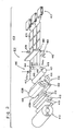
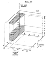
- FIG. 2 is a perspective view showing a schematic construction of a cutting apparatus 410 according to the invention
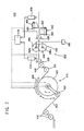
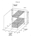
- FIG. 3 is a schematic side elevation of the cutting apparatus 410.
- FIG. 2 omits a portion of FIG. 3 .
- the cutting apparatus 410 is constructed mainly by arranging a heating unit 416 upstream of a cutter unit 414 for cutting a band-shaped thermal imaging material (or sheet material) 412.
- the band-shaped thermal imaging material 412 as let off from a web unwinder 413 having the thermal imaging material 412 rolled thereon, is transferred at a predetermined velocity by a main feed roller 421 by way of a transfer passage which is defined by a plurality of guide rollers 418 and a dancer roller 415 for adjusting the tension of the thermal imaging material 412.
- the thermal imaging material 412 thus transferred through the transfer passage is further transferred through the heating unit 416 and the cutter unit 414 in the recited order so that it is formed into a plurality of sheets 419, which are then stacked in a predetermined number on a sheet stacking unit 417.
- the heating unit 416 is equipped, as shown in FIGS. 2 to 4 , with a cylindrical heating roller 420 for heating the thermal imaging material 412 by contacting with it, and a holding roller 422 for holding the thermal imaging material 412 in engagement with it and for moving back and forth along the circumference of the heating roller 420.
- the heating roller 420 is supported at its journals 424 and 424 individually by bearings 426 and 428 so that the heating roller 420 rotates while following the thermal imaging material 412 being transferred in contact with its circumference.
- the bearing 428 on one side has a double bearing structure, around which there is disposed a sector gear 430 meshing with a motor shaft gear 434 of a reversibly rotatable motor 432.
- the toothless portion of the sector gear 430 and the holding roller 422 are connected through an L-shaped arm 436.
- the holding roller 422 reciprocates on the circumference of the heating roller 420 within the toothed range of the sector gear 430.
- the transfer passage of the thermal imaging material 412 is formed, as shown in FIGS. 2 and 3 , so that the thermal imaging material 412 is held in engagement with the holding roller 422 and then brought into contact with the heating roller 420, therefore, the lapping between the thermal imaging material 412 and the heating roller 420 can be enlarged by moving the holding roller 422 in the direction of arrow X but can be reduced by moving the holding roller 422 in the direction of arrow Y. This makes it possible to control the time period for the thermal imaging material 412 to be heated in contact by the heating roller 420.
- the holding roller 422 is moved in the direction to enlarge the lapping, when the thermal imaging material 412 has a high transfer velocity, but in the direction to reduce the lapping when the thermal imaging material 412 has a low transfer velocity. Then, the thermal imaging material 412 can be heated to a constant temperature even when the transfer velocity of the thermal imaging material 412 changes.
- the heat source for the heating roller 420 is not specifically shown but may be exemplified by a type having a heater in the heating roller 420, a type for heating the heating roller 420 by feeding steam thereinto, or another heat source.
- the heating unit 416 may be equipped with a blower unit 438 as an auxiliary heating unit, which is disposed in the vicinity of the circumference of the heating roller 420 and in an area not to obstruct the movement of the holding roller 422, for blowing at least one of a hot wind and a cold wind. If, in this case, the blower unit 438 is partitioned into a how wind blowing portion 438A and a cold wind blowing portion 438B, it is possible to blow one of or both of the hot wind and the cold wind.
- the blower unit 438 can blow at least one of the hot wind and the cold wind to the thermal imaging material 412 so that it can heat the thermal imaging material 412 to a temperature matching the lot even when the temperature adjustment of the heating roller 420 is not ended. At the lot changing time, therefore, the cutting operation can be performed continuously without interrupting the run of the cutting apparatus 410.
- the heat adjustment of the heating roller 420 can be promptly made by blowing at least one of the hot wind and the cold wind from the blower unit 438 to the heating roller 420.
- the blower unit 438 for blowing at least one of the hot wind and the cold wind is not limited in its arrangement to the position of the aforementioned heating unit 416.
- the blower unit 438 to be arranged at the position of the heating unit 416 may be dedicated exclusively to the hot wind, and a blower unit 439, as dedicated to the cold wind, may be arranged just upstream of each of a slitting machine 440 and a cross cutting machine 442, as will be described hereinafter (as should be referred to FIG. 3 ).
- the cutter unit 414 includes not only the slitting machine 440 and the cross cutting machine 442 but also a corner cutting machine, a notching machine, a boring machine or a trimming machine.
- the slitting machine 440 for cutting the thermal imaging material 412 into three rows, for example, in the transfer direction
- the cross cutting machine 442 for cutting the three rows of the thermal imaging material 412 in a cross direction perpendicular to the transfer direction into a predetermined length.
- the invention should not be limited to the arrangement of both the slitting machine 440 and the cross cutting machine 442 but may be exemplified by only one.
- the slitting machine 440 is equipped with first and second rotary blade members 444 and 446 which are arranged interposing the thermal imaging material 412 for slitting the thermal imaging material 412.
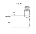
- the first rotary blade member 444 is set, as shown in FIG. 5 , to have an edge angle of ⁇ 1 degree, as made between a reference virtual line O normal to the planar direction of the thermal imaging material 412 and an edge line 450 containing a first edge 448 to contact at first with the image forming layer (or emulsion side surface) 412b of the thermal imaging material 412, within a range of 15 to 45 degrees or 85 to 90 degrees.
- the first rotary blade member 444 is provided with a predetermined relief angle of ⁇ 1 degrees from the reference virtual line O.
- the second rotary blade member 446 is set to have an edge angle of ⁇ 2 degrees, as made between an edge line 454 containing a second edge 452 to contact at first with a base layer 412a on the side opposed to the emulsion side surface of the thermal imaging material 412 and the reference virtual line O, within a range of 85 to 90 degrees.
- the second rotary blade member 446 is provided with a predetermined relief angle of ⁇ 2 degrees from the reference virtual line O and a rake angle of ⁇ 1 degrees from a plane parallel to the thermal imaging material 412.
- the first and second rotary blade members 444 and 446 are arranged in a partially overlapping state to have a predetermined biting depth H and is set with an angle, as made between their individual tangential lines from an overlapping point 456, i.e., a shear angle of ⁇ 1 degrees within a range of 10 to 20 degrees.
- the clearance C1 between the first and second edges 448 and 452 of the first and second rotary blade members 444 and 446 is set to a value of 15 % or less of the thickness of the thermal imaging material 412.
- This clearance C1 is set by forming a chamfered portion 458 at the outermost circumferential portion of one, e.g. , the second one 446 of the first and second rotary blade members 444 and 446.
- the individual relief angles of ⁇ 1 degrees and T2 degrees are set to 5 degrees or less, and the width size of the edge line 450 of the first rotary blade member 444 is set within a range of 0.1 to 1 mm when the edge angle of ⁇ 1 degrees is within a range of 85 to 90 degrees.
- the edge of the first rotary blade member 444 is set to have a shape shown in FIG. 7 .
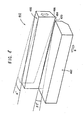
- the cross cutting machine 442 is equipped with first and second blade members 460 and 462 which are arranged across the thermal imaging material 412 for cross-cutting the thermal imaging material 412.
- the first blade member 460 constructs a moving blade whereas the second blade member 462 constructs a stationary blade.
- the first blade member 460 has a first edge 464 to contact at first with the image forming layer 412b of the thermal imaging material 412 and is set to have an edge angle of ⁇ 3 degrees, as made between an edge line 466 containing the first edge 464 and the reference virtual line O, within a range of 15 to 40 degrees or 85 to 90 degrees.
- the edge line 466 has a width of 0.1 to 15 mm.
- the shape is shown in FIG. 7 .
- the first blade member 460 is set with a relief angle of ⁇ 3 degrees from the reference virtual line, and this relief angle of ⁇ 3 degrees is set within a range of 5 degrees or less.
- the second blade member 462 is provided with a chamfered portion 468 and is set to have an edge angle of ⁇ 4 degrees, as made between an edge line 472 containing a second edge 470 to contact at first with the face of the thermal imaging material 412 on the side of the base layer 412a and the reference virtual line O, within a range of 85 to 90 degrees.
- the second blade member 462 is set to have a relief angle of ⁇ 4 degrees of 5 degrees or less from the reference virtual line O, and a rake angle of ⁇ 2 degrees from a plane in parallel with the thermal imaging material 412.
- the clearance between the first and second edges 464 and 470 is set to a value of 15 % or less of the thickness of the thermal imaging material 412.
- a shear angle of ⁇ 2 degrees for the first and second blades 464 and 470 to contain the thermal imaging material 412 is set within a range of 0.3 to 5 degrees.
- An intersection angle ⁇ degrees of the first and second blade members 460 and 462 is set within a range of 0 to 5/1,000 degrees, and a proper contact pressure is applied by setting the intersection angle to ⁇ ⁇ 0, when the clearance C2 is set to 0 %.
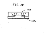
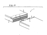
- the first and second blade members 460 and 462 are set in one direction with the shear angle of ⁇ 2 degrees, but there may be used first and second blade members 460a and 462a which are set with in two directions with the shear angle of ⁇ 2 degrees, as shown in FIG. 10 .
- the first blade member 460a can be set with a double shear angle for the same movement as that of the first blade member 460.
- first temperature sensor 474 for measuring the surface temperature of the thermal imaging material 412 on the emulsion side (or on the side of the image forming layer 412b) just before cut.
- second temperature sensor 476 for measuring the surface temperature of the thermal imaging material 412 on the emulsion side just after cut.
- the first and second temperature sensors 474 and 476 are preferably of the non-contact type and can be exemplified by an infrared thermography unit.
- the temperature information as measured by the first and second temperature sensors 474 and 476, are inputted to a controller 478, as shown in FIG. 3 .
- This controller 478 controls the heat source unit for the heating roller 420 and the heat source for the unit for moving and driving the holding roller 422 and for the blower units 438 and 439, thereby to control the surface temperatures of the thermal imaging material 412 on the emulsion side just before and after cut, within a range from the temperature Tg (or the glass transition temperature) of the image forming layer to the thermal imaging temperature, preferably, within a range from the temperature of Tg °C to 100 °C. It is more preferable if the range is from the temperature of (Tg + 5) °C to 100 °C.
- blade heating units for heating at least the blade portions of the slitting machine 440 and the cross cutting machine 442, so that the temperatures of the blades may be equalized to the surface temperature of the thermal imaging material 412 on the emulsion side when the thermal imaging material 412 is cut. At least the blade temperatures may preferably be contained within the temperature range from the Tg temperature (or the glass transition temperature) to the thermal imaging temperature, although not equalized to the surface temperature on the emulsion side.
- the blade heating apparatus for the slitting machine 440 can adopt a structure in which the journals 444a and 446a of the first and second rotary blade members 444 and 446 are formed in cylinder shapes so that the hot water or steam, as produced by a heat source supply unit 480, may be supplied from one to the other of the journals 444a and 446a and circulated again to the heat source supply unit 480.
- the blade heating apparatus for the cross cutting machine 442 can adopt a structure in which a heater 482 is buried or fixed in the first and second blade members 460 and 462 thereby to heat the same.
- thermography units for measuring the temperatures of the blades of the slitting machine 440 and the cross cutting machine 442, so that the measured information of the infrared thermography units may be inputted to the controller 478 to control the temperature of the blade of the cutter unit 414 as in the aforementioned temperature control of the heating unit 416.
- This temperature Tg is determined from the point of inflection of the hardnesses of the image forming layer 412b, which are measured at various temperatures under the circumstance of a relative moisture of 50 %.
- a miniature hardness meter of Fisher Scope H100VP for a sensitive layer and a Vickers pressure probe (having a facing angle of 136 degrees) are used, and the Vickers pressure probe is pushed into the image forming layer 412b to a depth of 50 % of the film thickness.
- the image forming layers 412b is present on the two sides of the support, on the other hand, there are determined the individual temperatures Tg, of which the higher one is employed as the temperature Tg of the invention.
- the thermal imaging material 412 to be let off from the web unwinder 413 and transferred through the transfer passage is heated in advance by the heating unit 416 before it is cut by the cutter unit 414.
- How high the thermal imaging material 412 is to be heated by the heating unit 416 is set so that the surface temperature of the thermal imaging material 412 on the emulsion side may fall, when cut, within a range from the temperature Tg (or the glass transition temperature) of the image forming layer 412b to the thermal imaging temperature, preferably within a range from a temperature of (Tg + 5) °C to 100 °C.
- the image forming layer 412b becomes soft to lose the fragility before heated, so that the image forming layer 412b can be prevented, when cut by the cross cutting machine 442, from separating or cracking and from peeling from the base layer 412a. If, in this case, the temperatures of the blades of the slitting machine 440 and the cross cutting machine 442 are equalized to the surface temperature of the thermal imaging material 412 on the emulsion side, no heat transfer occurs between the thermal imaging material 412 and the blades. As a result, the temperature distribution hardly occurs in the thermal imaging material 412 so that the thermal imaging material 412 can be cut more satisfactorily.
- the upper limit of the heating is set to the thermal imaging temperature or lower, or preferably to 100 °C or lower, on the other hand, the photographic performance of the image forming layer 412b in the thermal imaging material 412 is not deteriorated. It is further possible to prevent the heating temperature from growing excessively high and the image forming layer 412b from becoming too soft to cut. This raises an effect that the thermal imaging material 412 can be satisfactorily cut without causing the film separation or cracks of the image forming layer, independently of the blade shapes or the adjusting conditions of the upper blades of the slitting machine 440 and the cross cutting machine 442.
- the image forming layer 412b has a film thickness within a range of 3 to 30 ⁇ m in addition to the aforementioned heating to the proper temperature. This is because if the film thickness of the image forming layer 412b is less than 3 ⁇ m, the temperature rise of the image forming layer 412b is so accelerated at the heating time whereas the temperature drop in the course from the heating apparatus 416 to the cutter unit 414 is so increased, thereby to make it difficult to control the temperature of the image forming layer 412b.
- the temperature measurement of the image forming layer 412b cannot be grasped without measuring the surface temperature of the thermal imaging material 412 on the emulsion side.
- the image forming layer 412b grows thicker than 30 ⁇ m, therefore, a temperature distribution is easily established between the portions close to and distant from the surface of the image forming layer 412b.
- the entirety of the image forming layer 412b is hardly kept homogeneous in the aforementioned temperature range, thereby to cause the film separation and crack of the image forming layer 412b at the cutting operation.
- the first and second rotary blade members 444 and 446 are rotationally driven so that they and their first and second edges 448 and 452 contact at first with the surfaces of the image forming layer 412b and the base layer 412a of the thermal imaging material 412 to start the cutting of the thermal imaging material 412.
- the first and second rotary blade members 444 and 446 overlap each other in the predetermined biting depth H so that the thermal imaging material 412 is slit in the direction of arrow X under the rotary actions of the first and second rotary blade members 444 and 446.
- the first and second blade members 460 and 462 are arranged in the width direction (or in the direction of arrow Y) perpendicular to the let-off direction (or in the direction of arrow X) of the thermal imaging material 412, and the first blade member 460 moved up and down with respect to the second blade member 462.
- the first and second edges 464 and 470 of the first and second blade members 460 and 462 begin contacting with the image forming layer 412b and the base layer 412a along the widthwise direction of the thermal imaging material 412, thereby to cross-cut the thermal imaging material 412.
- three rows of sheets 419 are simultaneously formed and transferred in the X direction until they are stacked in a predetermined number on the sheet stacking unit 417 (as referred to FIG. 2 ).
- the individual evaluation items in Table 1 are enumerated from the left to the right in the recited order of the surface layer cracks 5, the surface layer peels 4 and the crack 6 in the image forming layer 3.
- the clearance C2 is set to a predetermined value of 15 % or less.
- the thermal imaging material 412 can be cut in a high quality without any trouble. More detailed experiments were performed for the edge angle of ⁇ 3. In these experiments, the satisfactory results were obtained within the ranges of the edge angle of ⁇ 3 from 15 to 40 degrees and from 85 to 90 degrees.
- the aforementioned experiments are the results which were obtained by using the thermal imaging material 412 having the image forming layer 412b of a thickness of about 30 ⁇ m, but similar results are obtained even when similar experiments were performed by using a thermal imaging material 412 having an applied substance of a substantially identical composition and having a thickness of about 20 ⁇ m.
- Table 4 enumerates the experimental results which were obtained under the conditions of the shear angle of ⁇ 1 of 15 degrees and the clearance C1 of 0 %.
- the thermal imaging material 412 could be cut satisfactorily for the edge angle of ⁇ 1 within the ranges of 15 to 40 degrees and 85 to 90 degrees.
- the experiments were performed on whether or not the beard was formed in the base layer 412a, and their results are enumerated in Table 6.
- edge angles of ⁇ 1 and ⁇ 2 are set within the range of 15 to 40 degrees or 85 to 90 degrees but may be set preferably within a range of 25 to 35 degrees or 87.5 to 90 degrees and further preferably to a value of 30 to 90 degrees.
- FIG. 13 is a perspective view showing a schematic construction of a further cutting apparatus 500 according to the invention
- FIG. 14 is a schematic side elevation of the cutting apparatus 500.
- the same components as those of the cutting apparatus 410 are designated by the common reference numerals, and their detailed description will be omitted.
- This cutting apparatus 500 is provided with a heating unit 502 for heating the thermal imaging material 412 with a hot wind.
- This heating unit 502 is equipped, along the transfer passage of the thermal imaging material 412, with an upstream hot wind mechanism 504 arranged upstream of the thermal imaging material 412, and a downstream hot wind mechanism 506 arranged downstream of the same.
- these hot wind mechanisms 504 and 506 there are arrayed a number of nozzles 508 for injecting the hot wind.
- These nozzles 508 are supplied with the hot wind from the not-shown hot wind supply unit through air pipes 510.
- An amount of the hot wind flows to be supplied can be individually adjusted by flow adjusting valves (or flow adjusting means) 512 which are disposed in the air pipes 510 for the individual nozzles 508.
- the temperature information as measured by the first and second temperature sensors 474 and 476, are inputted to the controller 478, which adjusts the openings of the flow adjusting valves 512 individually. According to the transfer velocity of the thermal imaging material 412 to be transferred, moreover, the arrayed multiple nozzles 508 are opened/closed to make the blows variable, thereby to change the length of the heating area, as formed between the upstream hot wind mechanism 504 and the downstream hot wind mechanism 506, and to adjust the hot wind flow.
- the surface temperature of the thermal imaging material 412 on the emulsion side can be controlled to fall within a range from the Tg temperature (the glass transition temperature) of the image forming layer 412b to the thermal imaging temperature, preferably within a range from the (Tg + 5) °C to 100 °C.
- the temperature controls are difficult when the image forming layer 412b is thin. It is, therefore, preferable to make as short as possible the transfer distance of the thermal imaging material 412 from the heating units 416 and 502 to the cutter unit 414 and to form a (not-shown) tunnel of insulation plates or the like in the transfer passage.
- the organic silver salt to be used in the thermal imaging material 412 of the invention is a silver salt, which is relatively stable to a light but forms a silver image when it is heated to 80 °C or higher in the presence of an exposed optical catalyst (such as a latent image of a photosensitive silver halide) and a reducer.
- the organic silver salt may be any organic substance containing a source capable of reducing the silver ion. This non-photosensitive organic silver salt is described in paragraph numbers [0048] to [0049] of Japanese Laid-Open Patent Publication No. 10-62899 , on line 24 of page 18 to line 37 of page 19 of Unexamined Published European Patent Application No. 0803764A1 , in Unexamined Published European Patent Application No.
- the preferred silver salt of an organic acid is a long-chain aliphatic silver caboxylate (having a carbon number of 10 to 30, preferably 15 to 28).
- the organic silver salt is preferably exemplified by silver behenate, silver arachidate, silver stearate, silver oleate, silver laurate, silver caprate, silver myristate or silver palmitate, or their mixtures. Of these organic silver salts, it is preferable in the invention to use an organic silver salt containing 75 mol% or more behenate acid.
- the shape of the organic silver salt should not be specifically limited but may be acicular, baculiform, flat and scaly forms, and the organic silver salt of the scaly form is preferred.
- the value x is determined and is averaged to a value x (average).
- the scaly shape is determined if the value x (average) satisfies a relation of x (average) ⁇ 1.5, preferably, 20 ⁇ x (average) ⁇ 2.0.
- the acicular shape is determined if the value x (average) is within 1 ⁇ x (average) ⁇ 1.5.
- the side a can be deemed as the thickness of the flat particle, the main plane of which has the sides b and c.
- the average value of the side a is preferable within a range of 0.01 ⁇ m to 0.23 ⁇ m, more preferably within a range of 0.1 ⁇ m to 0.20 ⁇ m.
- the average ratio of c/b is preferably within a range of 1 to 6, more preferably within a range of 1.05 to 4, still more preferably within a range of 1.1 to 3, most preferably within a range of 1.1 to 2.
- the particle size distribution of the organic silver salt is preferred to be monodisperse.
- This monodispersion has such percentages, which are calculated by dividing the standard deviations of the lengths of the shorter axis and the longer axis respectively by the lengths of the shorter axis and the longer axis, as are preferably 100 % or less, more preferably 80 % or less, or still more preferably 50 % or less.
- the shape of the organic silver salt can be measured from the transmission type electron microscope image of the organic silver salt dispersion. Another method for measuring the monodispersion is to determine the standard deviation of the volume-weighted mean diameter of the organic silver salt.
- the percentages (or fluctuation coefficient) of the values, as divided by the volume-weighted mean diameter, are preferably 100 % or less, more preferably 80 % or less, or still more preferably 50 % or less.
- the particle size can be determined from that (or the volume-weighted mean diameter), as obtained by irradiating the organic silver salt dispersed in a liquid with a laser beam and by determining a self-correlation function of the fluctuation of the scattered beam with respect to the time change.
- the photosensitive silver salt coexists at the dispersion time of the organic silver salt, the fogging rises to lower the sensitivity seriously. It is, therefore, preferable that the photosensitive silver salt is not substantially contained at the dispersion time.
- the quantity of the photosensitive silver salt to be dispersed in a water dispersion is 0.1 mol% or less with respect to 1 mol of the organic acid silver salt in the solution, so that the photosensitive silver salt is not positively added.
- the water dispersion of the organic silver salt and the water dispersion of the photosensitive silver salt can be mixed to produce a photosensitive material, and the mixing ratio of the organic silver salt and the photosensitive silver salt can be selected for the purpose.
- the ratio of the photosensitive silver salt to the organic silver salt is preferably within a range of 1 mol% to 30 mol%, more preferably 3 mol% to 20 mol%, especially preferably within 5 mol% to 15 mol%. It is a preferably used method for adjusting the photographic characteristics to mix two kinds or more of water dispersions of organic silver salts and two kinds or more water dispersions of photographic silver salts.
- the organic silver salt can be used in a desired quantity, but the silver quantity is preferably within a range of 0.1 g/m 2 to 5 g/m 2 or more preferably within a range of 1 g/m 2 to 3 g/m 2 .
- the thermal imaging material 412 to be employed in the invention is preferred to contain a reducer for the organic silver salt.
- This reducer for the organic silver salt may be any substance (preferably an organic substance) for reducing silver ions to metallic silver. This reducer is described in paragraph numbers [0043] to [0045] of Japanese Laid-Open Patent Publication No. 11-65021 or on page 34 of page 7 to on line 12 of page 18 of Unexamined Published European Patent Application No. 0803764A1 .
- the reducer preferred especially in the invention is exemplified by bisphenol reducer (e.g., 1,1-bis (2-hydroxy-3,5-dimethylphenyl) -3,5,5-trimethylhexane, 2,2'-methylene bis-(4-methyl-6-tert-butylphenol), 2,2'-methylene bis-(4-ethyl-6-tert-butylphenol)).
- bisphenol reducer e.g., 1,1-bis (2-hydroxy-3,5-dimethylphenyl) -3,5,5-trimethylhexane, 2,2'-methylene bis-(4-methyl-6-tert-butylphenol), 2,2'-methylene bis-(4-ethyl-6-tert-butylphenol)
- the quantity of the reducer to be added is preferably within a range of 0.01 g/m 2 to 5.0 g/m 2 or more preferably within a range of 0.1 g/m 2 to 3.0 g/m 2 , and is more preferably contained by 5 mol% to 50 mol% with respect to one mol of silver in the face having the image forming layer 412b or more preferably by 10 mol% to 40 mol%.
- the reducer is preferably contained in the image forming layer 412b.
- the reducer may be contained in the liquid to be applied or in the photosensitive material, by any method including the solution state, the emulsified/dispersed state or the solid particle dispersed state.
- emulsifying/dispersing method there is enumerated a method for preparing an emulsified dispersion mechanically by dissolving with oil, e.g., dibutylphthalate, tricresyl phosphate, clyceryl triacetate or diethyl phthalate, or an assistant solvent, e.g., ethyl acetate or cyclohexanone.
- oil e.g., dibutylphthalate, tricresyl phosphate, clyceryl triacetate or diethyl phthalate
- an assistant solvent e.g., ethyl acetate or cyclohexanone.
- the solid particle dispersing method there is enumerated a method for preparing a solid dispersion by dispersing a reducer powder in a suitable solvent such as water by a ball mill, a colloid mill, a vibration ball miss, a sand mill, a jet mill, a roller mill or ultrasonic waves. Then, there may be used a protective colloid (e.g., polyvinyl alcohol) or a surface-active agent (e.g., an anionic surface-active agent such as triisopropyl naphthalene sodium sulfonate (i.e., a mixture of three isopropyl groups having different substitution positions)).
- the water dispersion can contain a preservative (e.g., sodium benzoisothiazolinone).
- thermal imaging material 412 to be employed in the invention there is preferably used as a development promotor a phenol derivative, as expressed by Formula (A) described in Japanese Laid-Open Patent Publication No. 11-73951 .
- the photosensitive silver halide to be employed in the thermal imaging material 412 employed in the invention should not be especially restricted in its halogen composition and can be exemplified by silver chloride, silver chloride-bromide, silver bromide, silver iodide-bromide or silver iodide-chloride-bromide.
- the distribution of the halogen composition in the particles may be homogeneous or stepwise or continuously changed.
- the structure is preferably a double to quintuple one, and more preferably core/shell particles having a double to quadruple structure can be used.
- the method of preparing the photosensitive silver halide is well known in the art, as described in No. 17029, June of 1978 of Research Disclosure and US Patent No. 3,700,458 .
- the photosensitive silver halide is prepared by adding a silver feeding compound and a halogen feeding compound to a gelatin or another polymer solution and is then mixed with the organic silver salt.
- there are preferred the method as described in paragraph numbers [0217] to [0224] of Japanese Laid-Open Patent Publication No. 11-119374 , and the method, as disclosed in Japanese Patent Application Nos. 11-98708 and 11-84182 .
- the particle size of the photosensitive silver halide is preferred to be small for suppressing the cloudiness of the formed image and is specified by 0.20 ⁇ m or less, more preferably within a range of 0.01 ⁇ m to 0.15 ⁇ m, further preferably within a range of 0.02 ⁇ m to 0.12 ⁇ m.
- the particle size is the diameter of a sphere having a volume equal to that of the silver halide particles, when the silver halide particles are the so-called "normal crystal” such as a cube or octahedron or when not the normal crystal such as spherical particles or baculiform particles, and the diameter of a circular image having the same area as the projected area of the principal surface when the silver halide particles are flat ones.
- the shape of the silver halide particles there can be enumerated the cubic shape, the octahedron shape, the flat particles, the spherical particles, the baculiform or the potato-shaped particles or the like, of which the cubic particles are especially preferred in the invention.
- the silver halide particles having rounded corners can be preferably used. No special restriction is on the indices of a plane (i.e., Miller indices) of the outer surfaces of the photosensitive silver halide particles, but it is preferable that the plane ⁇ 100 ⁇ having a high spectroscopic sensitizing efficiency when the spectroscopic sensitizing pigment is adsorbed takes a high ratio of occupation.
- the ratio is preferably 50 % or more, more preferably 65 % or further preferably 80 % or more.
- the ratio of the ⁇ 100 ⁇ plane of the Mirror indices can be determined by the method which is described in J. Imaging Sci., 29, 165 (1985) by T. Tani , as making use of the adsorption dependencies of the plane ⁇ 111 ⁇ and the plane ⁇ 100 ⁇ in the adsorption of the sensitizing pigment.
- the photosensitive silver halide particles in the thermal imaging material 412 to be employed in the invention contain either a metal of the eighth to tenth groups of the periodic table (indicating the first to eighteenth groups) or its complex.
- the central ones of the metals or their complexes of the eighth to tenth groups of the periodic table are preferably rhodium, ruthenium and iridium. It is arbitrary to use one kind of those metal complex or two or more kinds of complexes of the metal of the same kind or the metals of different kinds.
- a preferable rate of content is within a range of 1 x 10 -9 mols to 1 x 10 -3 mols for one mol of silver.
- the silver halide particles are preferred to contain an iridium compound.
- this iridium compound there are enumerated hexachloro iridium, hexaammine iridium, trioxalato iridium and hexcyano iridium. These iridium compounds are dissolved, when used, in water or a suitable solvent.
- an ordinary method such as the method of adding an water solution of hydrogen halide (e.g., hydrochloric acid, hydrobromic acid or hydrofluoric acid) or an alkali halide (e.g., KCl, NaCl, KBr or NaBr).
- iridium compounds are preferably within a range of 1 x 10 -8 mols to 1 x 10 -3 mols per mole of silver halide or more preferably within a range of 1 x 10⁻⁷ mols to 5 x 10 -4 mols.
- the metal atoms (e.g., [Fe(CN) 6 ] 4- ) to be contained in the silver halide particles in the thermal imaging material 412, as employed in the invention, the desalting method and the chemical sensitizing method of the silver halide emulsion are described in paragraph numbers [0046] to [0050] of Japanese Laid-Open Patent Publication No. 11-84574 , in paragraph numbers [0025] to [0031] of Japanese Laid-Open Patent Publication No. 11-65021 , and in paragraph numbers [0242] to [0250] of Japanese Laid-Open Patent Publication No. 11-119374 .
- the gelatin to be contained in the photosensitive silver halide emulsion can be various.
- gelatin having a molecular weight as low as 500 to 60,000 may be employed at the particle forming time or at the dispersion time after the desalting treatment but is preferably employed at the dispersion time after the desalting treatment.
- the sensitizing pigment to be applied to the thermal imaging material 412 employed in the invention there can be advantageously selected the sensitizing pigment which can sensitize the spectroscopy of the silver halide particles in a desired wavelength range when adsorbed by the silver halide particles and which has a spectroscopic sensitivity suited for the spectroscopic characteristics of the exposing light source.
- the sensitizing pigment and the adding method are described in paragraph numbers [0103] to [0109] of Japanese Laid-Open Patent Publication No. 11-65021 , as the compounds expressed by the general Formula (II) of Japanese Laid-Open Patent Publication No.
- sensitizing pigments may be used solely or in combination of two kinds or more.
- the addition of the sensitizing pigment to the silver halide emulsion is preferably timed after the desalting step and before its application or more preferably after the desalting and before the start of chemical aging.
- the amount of the sensitizing pigment to be added can be exemplified by a desired value according to the performances such as the sensitivity or fogging, but may be preferably within a range of 10 -6 mols to 1 mol per mole of the silver halide of the photosensitive layer or more preferably within a range of 10 -4 mols to 10 -1 mols.
- the thermal imaging material 412 to be employed in the invention can be exemplified by an intense color sensitizer so as to improve the spectroscopic sensitizing efficiency.
- an intense color sensitizer there are enumerated the compounds which are described in Unexamined Published European Patent Application No. 587,338 , US Patents Nos. 3,877,943 and 4,873,184 and Japanese Laid-Open Patent Publication Nos. 5-341432 , 11-109547 and 10-111543 .
- the photosensitive silver halide particles in the thermal imaging material 412 to be employed in the invention are preferred to be chemically sensitized by the sulfur sensitizing method, the selenium sensitizing method or the tellurium sensitizing method.
- the compounds to be preferably used in the sulfur sensitizing method, the selenium sensitizing method or the tellurium sensitizing method are exemplified by the well-known compounds such as those described in Japanese Laid-Open Patent Publication No. 7-128768 .
- the tellurium sensitizing method is preferred, and the preferable compounds are described in paragraph number [0030] of Japanese Laid-Open Patent Publication No. 11-65021 and are exemplified by general Formulas (II), (III) and (IV) of Japanese Laid-Open Patent Publication No. 5-313284 .
- the chemical sensitization can be timed at any time before the particle formation and before the application, as exemplified after the desalting and (1) before the spectroscopic sensitization, (2) simultaneously with the spectroscopic sensitization, (3) after the spectroscopic sensitization and (4) just before the application.
- the timing (3) after the spectroscopic sensitization is especially preferable.
- the amount of the sulfur, selenium or tellurium sensitizer to be used in the thermal imaging material 412 employed in the invention changes with the silver halide particles or the chemical aging conditions to be employed, but is within a range of 10 -8 mols to 10 -2 mols per mole of the silver halide or more preferably within a range of 10 -7 mols to 10 -3 mols.
- the chemical sensitizing conditions are not especially restricted, but the pH is 5 to 8; the pAg is 6 to 11; and the temperature is about 40 to 95 °C.
- the photosensitive silver halide emulsion in the thermal imaging material 412 to be employed in the invention may be of one kind or two or more kinds (which are different in the mean particle size, the halide composition, the crystal properties and the chemical sensitizing condition).
- the gradation can be adjusted by using a plurality of kinds of photosensitive silver halides of different sensitivities. As these techniques, there can be enumerated Japanese Laid-Open Patent Publication Nos. 57-119341 , 53-106125 , 47-3929 , 48-55730 , 46-5187 , 50-73627 57-150841 or the like.
- the sensitivity difference may be preferred to have a difference of 0.2 logE for each emulsion.
- the amount of the sensitive silver halide to be added is preferable, in terms of the amount of applied silver per 1 m 2 of the sensitizer, within a range of 0.03 g/m 2 to 0.6 g/m 2 , more preferably within a range of 0.05 g/m 2 to 0.4 g/m 2 , or most preferably within a range of 0.1 g/m 2 to 0.4 g/m 2 .
- the photosensitive silver halide is preferably within a range of 0.01 mols to 0.5 mols, or more preferably within a range of 0.02 mols to 0.3 mols.
- the mixing method and the mixing conditions of the sensitive silver halide and the organic silver salt prepared separately there is: the method of mixing the silver halide particles and the organic silver salt prepared separately, by the high-speed agitator, the ball mill, the sand mill, the colloid mill, the vibration mill and the homogenizer; or the method of mixing the photosensitive silver halide, as having been prepared at any timing of the organic silver salt being prepared, to prepare the organic silver salt.
- the method is not especially limitative so long as the effect of the invention sufficiently appears.
- the preferable timing for adding the silver halide of the thermal imaging material 412 to be employed in the invention into the applied liquid for the image forming layer is for the time period from 180 mins. to just before the application, preferably from 60 mins. to 10 secs. before the application. This timing is not especially limitative so long as the effects of the invention sufficiently appear.
- the specific mixing method is exemplified by the method of mixing in the tank so that the average residual time calculated from the addition flow rate and the feed rate to the coater may be a desired one, or by the method employing the static mixer, as described in Section 8 of " Liquid Mixing Technique" (published by Nikkan Kogyo Sinbunsha, in 1989), edited by N. Harnby, M. F. Edwards & A. W. Nienow and translated by Kohji Takahashi .
- the binder of the organic silver salt containing layer of the thermal imaging material 412 to be used in the invention may be any polymer, and the suitable binder is transparent or semitransparent and generally colorless and is exemplified by a natural polymer synthetic resin, a polymer or a copolymer, or a medium forming other films, such as: gelatin, acacia gum, polyvinyl alcohol, hydroxyethyl cellulose, cellulose acetate, cellulose acetate butylate, poly (vinylpyrolidone), casein, starch, poly (acrylic acid), poly (methyl methacrylate), poly (vinyl chloride), poly (methacrylate), copolymer of styrene-maleic unhydride, copolymer of styrene-acrylonitrile, copolymer of styrene-butadiene, poly (vinyl acetal) (e.g., poly (vinyl formal) and poly (vinylbutyral)),
- the organic silver salt containing layer is improved when it is formed by using an applied liquid containing 30 wt.% or more of water of the solvent and by drying it and when its binder is made of latex of a polymer which can be dissolved or dispersed in a water type solvent (or water solvent) and which has an equilibrium water content of 2 wt.% or less at 25 °C and at 60 %RH.
- the most preferable state is obtained by preparing the organic silver salt containing layer to have an ion conductivity of 2.5 mS/cm or less, and this preparing method is exemplified by the method of purifying with a film having a separating function after the polymer was synthesized.
- the aforementioned water type solvent in which the polymer can be dissolved or dispersed, is either water or a mixture containing 70 wt.% or less of a water-blendable organic solvent and water.
- the water blendable organic solvent can be exemplified by: an alcohol group including methyl alcohol, ethyl alcohol and propyl alcohol; a cellosolve group including methyl cellosolve, ethyl cellosolve and butyl cellosolve; ethyl acetate; and dimethyl formamido.
- the system in which the polymer is not thermodynamically dissolved but is present in the so-called “disperse state", is also termed as the "water type solvent".
- the equilibrium water content at 25 °C and 60 %RH of the binder polymer of the thermal imaging material 412 to be employed in the invention is preferably 2 wt.% or less, more preferably within a range of 0.01 wt.% to 1.5 wt.%, further preferably within a range from 0.02 wt.% to 1 wt.%.
- the polymer which can be dispersed in the water type solvent there is preferred the polymer which can be dispersed in the water type solvent.
- the dispersed state may be exemplified either by the latex, in which the fine particles of water-insoluble hydrophobic polymer are dispersed, or by the dispersion of the polymer molecules in the molecule state or micelle.
- the mean diameter of the disperse particles is preferably within a range of 1 nm to 50,000 nm or more preferably within a range of about 5 nm to 10,000.
- the diameter distribution of the disperse particles should not be especially limited but may have a wide diameter distribution or a monodisperse diameter distribution.
- a hydrophobic polymer such as an acrylic resin, a polyester resin, a rubbery resin (e.g., the SBR resin), a polyurethane resin, a vinyl chloride resin, a vinyl acetate resin, a vinylidene chloride resin or a polyolefin resin.
- copolymers may be random copolymers or block copolymers. These polymers may have a number average molecular weight of 5,000 to 1,000,000 or preferably 10,000 to 200,000. The polymers having an excessively small molecular weight is insufficient in the dynamic strength of the emulsion layer, whereas the polymers having an excessively large molecular weight is not preferable because its filming property is poor.
- the preferred polymer latex can be specifically enumerated, as follows.
- the polymer latexes are expressed by their material monomers, and the parenthesized numerical values indicate the wt.% whereas the molecular weights (MW) indicate the number average molecular weights.
- P-1 Latex (MW 37,000) of -MMA(70)-EA(27)-MAA(3)
- P-2 Latex (MW 40,000) of -MMA(70)-2EHA(20)-St(5)-AA(5)
- P-3 Latex (MW 45,000) of -St(50)-Bu(47)-MMA(3)-
- P-4 Latex (MW 60,000) of -St(68)-Bu(29)-AA(3)-
- P-5 Latex (MW 120,000) of -St(70)-Bu(27)-IA(3)-
- P-6 Latex (MW 108,000) of -St(75)-Bu(24)-AA(1)-
- P-7 Latex (MW 150,000) of -St(60)-Bu(35)-DVB(3)-MAA(2)-
- P-8 Latex (MW 280,000) of -St(70)-Bu(25)-DVB(2)-AA(3)-
- P-9 Latex (MW 80,000) of -VC(50)-
- MMA methyl methacrylate
- EA ethyl acrylate
- MMA methacrylic acid
- 2EHA diethyl hexyl acrylate
- St styrene
- Bu butadiene
- AA acrylic acid
- DVB divinyl benzene
- VC vinyl chloride
- AN acrylonitrile
- VDC vinylidene chloride
- Et ethylene
- IA itaconic acid.
- the polymer latexes thus far enumerated are commercially available, as follows.
- the acrylic resins are exemplified by: Cebian A-4635, 46583 and 4601 (Daiseru Kagaku Kogyo KK); and Ni pol Lx 811, 814, 821, 820 and 857 (Nippon Zeon KK).
- the polyester resins are exemplified by: FINETEX ES 650, 611, 675 and 850 (Dainippon Inki KK); and WD-size and WMS (Eastman Chemical KK).
- the polyurethane resins are exemplified by HYDRAN AP 10, 20, 30 and 40 (Dainippon Inki Kagaku KK).
- the rubbery resins are exemplified by: LACSTAR 7310K, 3307B, 4700H and 7132C (Dainippon inki Kagaku KK); and Nipol Lx 416, 410, 438C and 2507 (Nippon Zeon KK).
- the vinyl chloride resins are exemplified by G351 and 576 (Nippon Zeon KK).
- the vinylidene chloride resins are exemplified by L502 and 513 (Asahi Kasei Kogyo KK).
- the olefin resins are exemplified by CHEMIPEARL S120 and S A100 (Mitsui Sekiyu Kagaku KK).
- polymer latexes may be used singly, or two or more kinds may be blended, if necessary.
- the latex to be used in the thermal imaging material 412 employed in the invention there is preferred the latex of the styrene-butadiene copolymer. It is preferred that the weight ratio between the monomer unit of the styrene in the styrene-butadiene copolymer and the monomer unit of the butadiene is 40 : 60 to 95 : 5. It is also preferred that the ratio to be occupied by the copolymer of the styrene monomer unit and the butadiene monomer unit is 60 wt.% to 99 wt.%. The preferable molecular weight range is similar to the aforementioned one.
- the latex of the styrene-butadiene copolymer to be preferably used in the thermal imaging material 412 employed in the invention there are enumerated the aforementioned P-3 to P-8 and the commercially available LACSTAR-3307B, 7132C, Nipol Lx416.
- a hydrophilic polymer such as gelatin, polyvinyl alcohol, methyl cellulose, hydroxy propyl cellulose or carboxy methyl cellulose.
- the amount of these hydrophilic polymers to be added is preferably 30 wt.% or less of the whole binder of the organic silver salt containing layer, or more preferably 20 wt.% or less.
- the organic silver salt containing layer (i.e., the image forming layer 412b) is preferably formed by using the polymer latex.
- the amount of the binder of the organic silver salt containing layer is preferred to have a weight ratio of the whole binder / the organic silver salt within a range of 1/10 to 10/1 or more preferably within a range of 1/5 to 4/1.
- organic silver salt containing layer is ordinarily exemplified by a photosensitive layer (or emulsion layer) containing a photosensitive silver halide, i.e., a photosensitive silver salt.
- a photosensitive layer or emulsion layer
- the weight ratio of the whole binder / the silver halide is preferably within a range of 400 to 5, or more preferably within a range of 200 to 10.
- the total binder amount of the image forming layer 412b of the thermal imaging material 412 to be employed in the invention is preferably 0.2 g/m 2 to 30 g/m 2 , or more preferably within a range of 1 g/m 2 to 15 g/m 2 .
- a cross linking agent and a surface-active agent for improving the applicability.
- the solvent (which cover the solvent and the dispersing agent, for simplicity) for applying a liquid for the organic silver salt containing layer of the thermal imaging material 412 to be employed in the invention is a water type solvent containing 30 wt.% or more of water.
- the components other than the water may be a water-blendable organic solvent such as methyl alcohol, ethyl alcohol, isopropyl alcohol, methyl cellosolve, ethyl cellosolve, dimethyl formamido or ethyl acetate.
- the water content of the solvent of the applied liquid is preferably 50 wt.% or more, or more preferably 70 wt.% or more.
- the fogging preventing agent, the stabilizer and the stabilizer precursor, as can be used in the thermal imaging material 412 to be used in the invention are exemplified by those which are described in paragraph number [0070] of Japanese Laid-Open Patent Publication No. 10-62899 and on line 57 of page 20 to line 7 of page 21 of Unexamined Published European Patent Application No. 0803764A1 .
- the fogging preventing agent to be preferably used in the invention is exemplified by organic halides, which are enumerated in paragraph numbers [0111] to [0112] of Japanese Laid-Open Patent Publication No. 11-65021 .
- the preferable examples are the organic halides expressed by Formula (P) of Japanese Laid-Open Patent Publication No. 11-87297 or the organic polyhalides expressed by the general Formula (II) of Japanese Laid-Open Patent Publication No. 10-339934 (as specified by tribromo methyl naphtyl sulfone, tribromo methyl phenyl sulfone, bromo methyl (4-(2,4,6-trimethyl phenyl sulfonyl) phenyl) sulfone).
- the method for incorporating the fogging preventing agent of the thermal imaging material 412 to be employed in the invention into the photosensitive material is exemplified by the method described in the aforementioned reducer incorporating method, and the organic polyhalides may be added in the disperse state of the solid fine particles.
- the remaining fogging preventing agents there can be enumerated the mercury (II) salt of paragraph number [0113] of Japanese Laid-Open Patent Publication No. 11-65021 , the benzoic acids of paragraph number [0114] of the same, the salicylic acid derivatives expressed by Formula (Z) of Japanese Laid-Open Patent Publication No. 11-87297 , and the formalin scavengers expressed by Formula (S) of Japanese Laid-Open Patent Publication No. 11-23995 .
- the mercury (II) salt of paragraph number [0113] of Japanese Laid-Open Patent Publication No. 11-65021 the benzoic acids of paragraph number [0114] of the same
- the salicylic acid derivatives expressed by Formula (Z) of Japanese Laid-Open Patent Publication No. 11-87297
- the formalin scavengers expressed by Formula (S) of Japanese Laid-Open Patent Publication No. 11-23995 .
- the thermal imaging material 412 to be employed in the invention may contain azolium salt with a view to preventing the fogging.
- azolium salt there can be enumerated a compound expressed by the general Formula (XI) described in Japanese Laid-Open Patent Publication No. 59-193447 , a compound expressed by the general Formula (XI) described in Examined Published Japanese Patent Application No. 55-12581 , and a compound expressed by the general Formula (II) described in Japanese Laid-Open Patent Publication No. 60-153039 .
- the azolium salt may be added at any step of the photosensitive material and may be applied to the organic silver salt containing layer at any step from the organic silver salt preparing time to the applied liquid preparing time but preferably after the organic silver salt preparing time just before the application.
- the method of adding the azolium salt may be performed in any state of the powder, solution or fine particle dispersion.
- the azolium salt may be added as its solution mixed with another additive such as the sensitizing pigment, reducer or color toner.
- the amount of the azolium salt to be added may be any but is preferably within a range of 1 x 10 -6 mols to 2 mols for 1 mol of silver, or more preferably within a range of 1 x 10 -3 mols to 0.5 mols.
- the thermal imaging material 412 to be employed in the invention can contain mercapto compounds, disulfide compounds and thion compounds, such as the compounds described in paragraph numbers [0067] to [0069] of Japanese Laid-Open Patent Publication No. 10-62899 , the compounds expressed by the general Formula (I) and their specific examples described in paragraph numbers [0033] to [0052] of Japanese Laid-Open Patent Publication No. 10-186572 , and the specific examples described on lines 36 to 56 of page 20 of Unexamined Published European Patent Application No. 0803764A1 and in Japanese Laid-Open Patent Publication No. 11-273670 . Of these compounds, mercapto-substituted heteroaromatic chemicals are preferred.
- thermal imaging material 412 to be employed in the invention there are preferably used compounds having phosphoryl groups or more preferably phosphine oxido groups, as specified by: triphenyl phosphine oxido, tri-(4-methyl phenyl) phosphine oxido, tri-(4-methoxy phenyl) phosphine oxido, tri-(t-butyl-phenyl) phosphine oxido, tri-(3-methyl phenyl) phosphine oxido or trioctyl phosphine oxido.
- the compounds having the phosphoryl group of the invention can be introduced into the sensitive material by a method similar to those of the reducer and the poly halides.
- the amount of the compounds having the phosphoryl group of the invention is preferably within a range of 0.1 to 10 for the addition ratio (in molar ratio) of the reducer, more preferably within a range of 0.1 to 2.0, or further preferably within a range of 0.2 to 1.0.
- the color toner is preferably added to the thermal imaging material 412 to be employed in the invention.
- the color toner is described in paragraph numbers [0054] to [0055] of Japanese Laid-Open Patent Publication No. 10-62899 , on lines 23 to 48 of page 21 of Unexamined Published European Patent Application No. 0803764A1 and in Japanese Patent Application No. 10-213487 .
- phthalazinone or its derivatives or metallic salts or derivatives of 4-(1-naphtyl) phthalazinone, 6-chlorophthalazinone, 5,7-dimethoxy phthalazinone and 2,3-dihydro-1,4-phthalazine dione
- combinations of phthalazinone and derivatives of phthalic acid e.g., phthalic acid, 4-methyl phthalic acid, 4-nitrophthalic acid and tetrachlor phthalic anhydride
- phthalazine groups phthalazine, derivatives of phthalazine or metallic salts of phthalazine, or derivatives of 4-(1-naphthyl) phthalazine, 6-isopropyl phthalazine, 6-t-butyl phthalazine, 6-chloro phthalazine, 5,7-dimethoxy phthalazine and 2,3-dihydro phthalazine
- the plasticizer and lubricant to be used in the photosensitive layer of the thermal imaging material 412 employed in the invention are described in paragraph number [0117] of Japanese Laid-Open Patent Publication No. 11-65021 ; the super hardening agent for forming a super hard image is described in paragraph number [0118] of the same, in paragraph numbers [0136] to [0193] of Japanese Laid-Open Patent Publication No. 11-223898 , as the compounds of Formulas (H), (1) to (3), (A) and (B) of Japanese Laid-Open Patent Publication No. 11-98297 and as the compounds (e.g., specific examples: compounds 21 to 24) of general Formulas (3) to (5) of Japanese Laid-Open Patent Publication No.
- the side having the image forming layer 412b containing the photosensitive silver halide is preferred to contain 5 mm mols or less of formic acid or formate per 1 mol of silver, or preferably 1 mm mols or less.
- the thermal imaging material 412 to be employed in the invention is preferably used, when it uses the nucleator, with either the acid, as produced by hydrating diphosphorous pentoxide, or its salt can be exemplified by methaphosphoric acid (or salt), pyrophosphoric acid (or salt), orthophosphoric acid (or salt), phosphoric acid (or salt), tetraphosphoric acid (or salt) or hexametaphosphoric acid (or salt).
- the especially preferably used salt, as produced by hydrating diphosphorous pentoxide, or its salt can be exemplified by orthophosphoric acid (or salt) or hexametaphosphoric acid.
- these specific salts there can be enumerated sodium orthophosphate, dihydrogen orthophosphate, sodium hexametaphosphate or ammonium hexametaphosphate.
- the used amount (or the amount of application per 1 m 2 of the photosensitive material) of the acid, as produced by hydrating diphosphorous pentoxide, or its salt may be at a desired value according to the performances such as the sensitivity and the fogging and is preferably within a range of 0.1 mg/m 2 to 500 mg/m 2 , or more preferably within a range of 0.5 mg/m 2 to 100 mg/m 2 .
- the thermal imaging material 412 to be employed in the invention can be provided with a surface protecting layer with a view to preventing the image forming layer 412b from sticking.
- the surface protecting layer is described in paragraph numbers [0119] and [0120] of Japanese Laid-Open Patent Publication No. 11-65021 .
- polyvinyl alcohol As the binder for the surface protecting layer, there is preferred gelatin, but there is preferably used polyvinyl alcohol (PVA). As this PVA, there are enumerated the completely saponified PVA-105, the partially saponified PVA-205, PVA-335, and the modified polyvinyl alcohol MP-203 (i.e., Trade Names of Kurare KK).
- the amount (per 1 m 2 of the support) of polyvinyl alcohol to be applied to the protecting layer (per one layer) is preferably within a range of 0.3 g/m 2 to 4.0 g/m 2 , or more preferably within a range of 0.3 g/m 2 to 2. 0 g/m 2 .
- polymer latex in the protecting layer and the back layer.
- This polymer latex is described in " Synthetic Resin Emulsion (edited by Taira Okuda and Hiroshi Inagaki, issued by KOBUNSHI KANKOKAI, INC. (1978 )", in “ Applications of Synthetic Latex (edited by Takaaki Sugimura, Yasuo Kataoka, Soichi Suzuki and Keiji Kasahara, issued by KOBUNSHI KANKOKAI, INC.
- the polymer latex can be exemplified by: a coplymer latex of methyl methacrylate (33.5 wt.%) / ethyl acrylate (50 wt.%) / methacrylic acid (16.5 wt.%); a copolymer latex of methyl methacrylate (47.5 wt.%) / butadiene (47.5 wt.%) / itaconic acid (5 wt.%); a copolymer latex of methyl methacrylate (58.9 wt.%) / 2-ethylhexyl acrylate (25.4 wt.%) / styrene (8.6 wt.%) / 2-hydroxyethyl methacrylate (5.1 wt.%) / acrylic acid (2.0 wt.%);
- the ratio of the polymer latex of the protecting layer is preferably within a range 10 wt.% to 90 wt.% of the whole binder, or especially preferably within a range of 20 wt.% to 80 wt.%.
- the amount of application (per 1 m 2 of the support) of the whole binder (including the water-soluble polymer and the latex polymer) of the protecting layer (per one layer) is preferably within a range of 0.3 g/m 2 to 5.0 g/m 2 or more preferably within a range of 0.3 g/m 2 to 2.0 g/m 2 .
- the temperature for preparing the liquid to be applied to the image forming layer of the thermal imaging material 412 employed in the invention is preferably within a range of 30 °C to 65 °C. more preferably within a range of 35 °C to 60 °C, or further preferably within a range of 35 °C to 55 °C.
- the temperature of the liquid to be applied to the image forming layer just after the addition of the polymer latex is preferably kept within a range of 30 °C to 65 °C. It is also preferable to mix the reducer and the organic silver salt before the polymer latex is added.
- the organic silver salt containing fluid or the thermal image forming layer applied liquid in the thermal imaging material 412 to be employed in the invention is preferably exemplified by the so-called "thixotropy fluid".
- This thixotropy means the property that the viscosity drops as the shearing rate increases.
- Any apparatus may be employed for measuring the viscosity, but the RFS fluid spectrometer made by Rheometric Far East KK is preferably used to measure the viscosity at 25 °C.
- the organic silver salt containing fluid or the thermal image forming layer applied liquid in the invention has, at a shearing rate of 0.1 S -1 , a viscosity preferably within a range of 400 mPa ⁇ s to 100,000 mPa ⁇ s or more preferably within a range of 500 mPa ⁇ s to 20,000 mPa ⁇ s.
- the viscosity is preferably within a range of 1 mPa ⁇ s to 200 mPa ⁇ s, or more preferably within a range of 5 mPa ⁇ s to 80 mPa ⁇ s.
- the thermal imaging photographic emulsion of the thermal imaging material 412 to be employed in the invention is formed as one or more layers over the support.
- the construction of one layer has to contain the organic silver salt, the silver halide, the developer, the binder, and desired additional materials such as the color toner, the coating assistant and another auxiliary agent.
- the construction of two layers has to contain the organic silver salt and the silver halide in the first emulsion layer (usually adjacent to the support) and has to contain several other components in the second layer or in both the layers. It is, however, conceivable to make the construction of two layers: a single emulsion layer containing all the components; and a protective top coating.
- the construction of the multicolor photosensitive thermal imaging photographic material may contain those combinations of two layers for each color or may contain all the components in the single layer, as described in US Patent No. 4,708,928 .
- the individual emulsion layers are generally held separately from one another, as described in US Patent No. 4,460,681 , by employing a functional or unfunctional barrier layer between the individual photosensitive layers.
- the various dyes and pigments e.g., C.I. Pigment Blue 60, C.I. Pigment Blue 64 and C.I. Pigment Blue 15:6 can be used in the photosensitive layer of the thermal imaging material 412 to be employed in the invention.
- C.I. Pigment Blue 60, C.I. Pigment Blue 64 and C.I. Pigment Blue 15:6 can be used in the photosensitive layer of the thermal imaging material 412 to be employed in the invention.
- the antihalation layer can be disposed at a remoter side from the light source with respect to the photosensitive layer.
- the thermal imaging material 412 generally has a non-photosensitive layer in addition to the photosensitive layer.
- the non-photosensitive layer can be sorted, from its arrangement, into: (1) a protective layer over (apart from the support) the photosensitive layer; (2) an intermediate layer interposed between the plurality of photosensitive layers or between the photosensitive layers and the protective layer; (3) a prime coat layer interposed between the photosensitive layer and the support; and (4) a back layer disposed on the opposite side of the photosensitive layer.
- the filter layer is formed as the layer (1) or (2) on the photosensitive material.
- the antihalation layer is formed as the layer (3) or (4) on the photosensitive material.
- the antihalation layer is described in paragraph numbers [0123] and [0124] of Japanese Laid-Open Patent Publication No. 11-65021 and in Japanese Laid-Open Patent Publication Nos. 11-223898 , 9-230531 , 10-36695 , 10-104779 , 11-231457 , 11-352625 and 11-352626 .
- the antihalation layer contains an antihalation dye having an absorption in the exposure wavelength.
- an infrared absorption dye may be used, and then a dye having no absorption in the visible range is preferred.
- the amount of the decoloring dye to be added is determined according to its application. Generally, the decoloring dye is employed in such an amount that an optical density (or optical absorption) when measured in the target wavelength may exceed 0.1.
- the optical density is preferably within a range of 0.2 to 2.
- the amount of dye to be employed to attain such optical density is generally within a range of 0.001 g/m 2 to 1 g/m 2 .
- the optical density after the thermal imaging can be reduced to 0.1 or less if the dye is decolored.
- Two or more kinds of decoloring dyes could be together in the thermal decoloring recording material or the thermal imaging material 412.
- two or more kinds of basic precursors can be used together.
- the decoloring dye and the basic precursor it is preferable to use such a substance (e.g., diphenyl sulfone or 4-chlorophenyl (phenyl) sulfone) as to lower the melting point by 3 °C or more (in degrees) when mixed with the basic precursor described in Japanese Laid-Open Patent Publication No. 11-352626 .
- a substance e.g., diphenyl sulfone or 4-chlorophenyl (phenyl) sulfone
- a coloring agent having an absorption maximum within a range of 300 nm to 450 nm, so as to improve the silver color tone and the aging of the image.
- This coloring agent is described in Japanese Laid-Open Patent Publication Nos. 62-210458 , 63-104046 , 63-103235 , 63-208846 , 63-306436 , 63-314535 and 01-61745 , and in Japanese Patent Application No. 11-276751 .
- This coloring agent is usually added within a range of 0.1 g/m 2 to 1 g/m 2 to the back layer on the side opposed to the photosensitive layer.
- the thermal imaging material 412 to be employed in the invention is preferably the so-called “one-side photosensitive material" which has the photosensitive layer containing at least one layer of silver halide emulsion on one side of the support and the back layer on the other side.
- the amount of the applied matting agent is preferably a range of 1 mg/m 2 to 400 mg/m 2 per 1 m 2 of the photosensitive material, or more preferably within a range of 5 mg/m 2 to 300 mg/m 2 .
- the matting degree of the emulsion surface is not restricted unless the start dust trouble occurs, but is preferably within a Beck's smoothness range of 30 secs. to 2,000 secs., especially preferably within a range of 40 secs. to 1,500 secs.
- the Beck's smoothness can be easily determined by "Smoothness Testing Method of Paper and Board by Beck Tester" of Japanese Industrial Standards (JIS) P8119 and by the TAPPI Standard Method T479.
- the Beck's smoothness is preferably within a range of 10 secs. to 1,200 secs., more preferably within a range of 20 secs. to 800 secs., or further preferably within a range of 40 secs. to 500 secs.
- the matting agent is preferably contained in the outermost surface layer of the photosensitive material, in the layer functioning as the outermost surface layer, in a layer close to the outer surface, or in a layer acting as the so-called "protective layer".
- the film surface before thermal imaging preferably has a pH of 6.0 or less, or preferably 5.5 or less. This lower limit is not restricted but to about 3.
- the ammonia is preferred for achieving a low film surface pH because it is so volatile that it can be removed at the application step or before the thermal imaging.
- the method of measuring the film surfaced pH is described in paragraph number [0123] of the Specification of Japanese Patent Application No. 11-87297 .
- a film hardening agent may be used in the individual layers such as the photosensitive layer, the protective layer or the back layer of the thermal imaging material 412 to be employed in the invention.
- the film hardening agent methods are described on page 77 to page 87 of "THE THEORY OF THE PHOTOGRAPHIC PROCESS FOURTH EDITION" (published by Macmillan Publishing Co., Inc. and in 1977) written by T. H. James.
- Multivalent metallic ions are preferably used in the description of page 78 of the same.
- polyisocyanates described in US Patent No. 4,281,060 and Unexamined Published Japanese said Patent Application No. 6-208193 epoxy compounds described in US Patent No. 4,791,042
- vinyl sulfone compounds described in Japanese Laid-Open Patent Publication No. 62-89048 .
- the film hardening agent is added as a solution, and the addition of this solution into the protective layer applied liquid is timed 180 mins. or just before the application, or preferably before 60 mins. to 10 mins. No especial restriction is on the mixing method and condition, so long as the effects of the invention are sufficed.
- a specific mixing method is exemplified by: a method of mixing in a tank so that the average residual time, as calculated from the added flow rate and the flow of the feed to a coater, may be a desired time; and a method of using a static mixer, as described in Section 8 or the like of " Liquid Mixing Techniques" (published by Nikkan Kogyo Sinbunsha, 1989) written by N. Harnby,, M.F. Edwards and A.W. Nienow and translated by Kohji Takahashi .
- the surface-active agent is described in paragraph number [0132] of Japanese Laid-Open Patent Publication No. 11-65021 ;
- the solvent is described in paragraph number [0133] of the same Japanese Patent Application;
- the support is described in paragraph number [0134] of the same Application;
- the antistatic treatment and the conductive layer are described in paragraph number [0135] of the same;
- the method of forming a color image is described in paragraph number [0136] of the same;
- the smoothing agent is described in paragraph numbers [0061] to [0064] of Japanese Laid-Open Patent Publication No. 11-84573 and in paragraph numbers [0049] to [0062] of Japanese Laid-Open Patent Publication No. 11-106881 .
- the transparent support is preferably made of the polyester or polyethylene terephthalate which has been subjected to a heat treatment within a temperature range of 130 °C to 185 °C, so as to relax the internal strain as might otherwise be left in the film at the biaxial orientation, and to eliminate the thermal shrinking strain as might otherwise occur in the thermal imaging.
- the transparent support may be either colored with a blue dye (e.g., Die-1 described in the Embodiment of Japanese Laid-Open Patent Publication No. 8-240877 ) or not.
- a blue dye e.g., Die-1 described in the Embodiment of Japanese Laid-Open Patent Publication No. 8-240877
- the thermal imaging material 412 to be employed in the invention is preferably of the mono-sheet type (which can form an image on the thermal imaging material 412 without employing another sheet such as an image receiving material).
- thermal imaging material 412 to be employed in the invention there may be further added an antioxidant, a stabilizer, a plasticizer, an ultraviolet ray absorber or a coating assistant.
- an antioxidant e.g., a sodium sulfate, sodium sulfate, sodium sulfate, sodium sulfate, sodium sulfate, sodium sulfate, sodium sulfate, sodium sulfate, sodium sulfate, sodium bicarbonate, sodium bicarbonate, sodium bicarbonate, sodium bicarbonate, sodium bicarbonate, sodium bicarbonate, sodium bicarbonate, sodium bicarbonate, sodium bicarbonate, sodium bicarbonate, sodium bicarbonate, sodium sulfate, sodium sulfate, sodium sulfate, sodium sulfate, sodium sulfate, sodium sulfate, sodium sulfate, sodium sulfate, sodium sulfate, sodium sulfate, sodium sulfate, sodium sulfate
- the thermal imaging material 412 to be employed in the invention may be coated by any method. This method is specified by: the extrusion coating, the slide coating, the curtain coating, the dipping coating, the knife coating or the flow coating; the various coating operations including the extrusion coating using the hopper of the kind described in US Patent No. 2,681,294 ; the extrusion coating or the slide coating described on page 399 to page 536 of "LIQUID FILM COATING" (published by CHAPMAN & HALL KK, 1997), written by Stephen F. Kistler and Petert M. Schweizer . Of these, the slide coating is especially preferably used. The examples of the shape of the slide coater to be employed in the slide coating are shown at b.1 of Fig.
- the thermal imaging material 412 to be employed in the invention may be developed in any method but is usually developed by heating the thermal imaging material which was image-wise exposed.
- the developing temperature is preferably within a range of 80 °C to 250 °C, or more preferably within a range of 100 °C to 140 °C.
- the developing time period is preferably within a range 1 sec. to 180 secs., more preferably within a range of 10 secs. to 90 secs., or especially preferably within a range of 10 secs. to 40 secs.
- the thermal imaging is preferably of the plate heater type.
- a preferable thermal imaging of this plate heater type is described in Japanese Laid-Open Patent Publication No. 11-133572 .
- the heating means includes a plate heater; in that a plurality of holding rollers are arranged to confront each other along one face of the plate heater; and in that the thermal imaging material is passed between the holding rollers and the plate heater so that it may be thermally imaged.
- the plate heater is preferably divided into two to six stages, so that the leading end portion may be lowered in temperature to about 1 to 10 °C.
- the thermal imaging material 412 to be employed in the invention may be exposed by any method, but a laser beam is preferred as the light source for the exposure.
- a laser beam is preferred as the light source for the exposure.
- the laser beam according to the invention there can be enumerated a gas laser (Ar + , He-Ne), a YAG laser, a pigment layer or a semiconductor laser.
- a gas laser Ar + , He-Ne
- YAG laser a YAG laser
- a pigment layer or a semiconductor laser it is possible to use both the semiconductor laser and a second harmonic wave generating element. What is preferred is a red or infrared ray emitting gas, or a semiconductor laser.
- the Fuji Medical Dry Laser Imager FM-DPL As a medical laser imager having an exposure unit and a thermal imaging unit, there can be enumerated the Fuji Medical Dry Laser Imager FM-DPL. This FM-DPL is described on pages 39 to 55 of Fuji Medical Review No. 8. These techniques can naturally be applied as the laser imager for the thermal imaging material 412 of the invention. The techniques can also be applied as the thermal imaging photosensitive materials for the laser imager in "ADnetwork", which has been proposed by Fuji Medical System as the network system conforming to the DICOM standards.
- the thermal imaging material 412 to be employed in the invention is preferred to form the black and white image with the silver and to be used as the thermal imaging materials for the medical diagnoses, as the industrial photographs, for the prints and for the COM.
- This film was longitudinally oriented 3.3 times by using rolls having different circumferential speeds and was then transversely oriented 4.5 times by a tenter.
- the temperatures at these orientations were 110 °C and 130 °C, respectively.
- the film was thermally fixed at 240 °C for 20 secs. and was transversely relaxed by 4 % at the same temperature.
- the portion chucked by the tenter was slitted, knurled at its two ends and taken up at 4 Kg/cm 2 to obtain a roll having a thickness of 175 ⁇ m.
- the solid state corona treating machine Model 6KVA of Pillar, INC. was used to treat the two sides of the support at a speed of 20 m/min. It was found from the read values of the current and the voltage that the support was treated at 0.375 Kv ⁇ A ⁇ min./m 2 .
- the treating frequency at this time was 9.6 kHz, and the gap clearance between the electrode and the dielectric roll was 1.6 mm.
- the biaxially oriented polyethylene terephthalate support having a thickness of 175 ⁇ m was subjected on their two sides to the corona discharge.
- the priming liquid of Formulation 1 was applied at 6.6 ml/m 2 (for one side) to one side (or the photosensitive layer side) of the support and was dried at 180 °C for 5 mins.
- the priming liquid of Formulation 2 was applied at 5.7 ml/m 2 by the wire bar to the back side and was dried at 180 °C for 5 mins.
- the priming liquid of Formulation 3 was applied at 7.7 ml/m 2 by the wire bar to the back side and was dried at 180 °C for 6 mins.
- the primed support was prepared.
- the container was kept at 40 °C, and 50g of gelatin, 0.2 g of sodium polystyrene sulfonate, 2.4 g of N,N-ethylene-bis (vinyl sulfone acetamido), 1 g of sodium t-octyl phenoxy ethoxy ethane sulfonate, 30 mg of benzo isothiazolinon, 37 mg of potassium salt of N-perfluoro octyl sulfonyl-N-propyl alanine, 0.15 g of polyethylene glycol mono (N-perfluoro octyl sulfonyl-N-propyl-2-aminoethyl) ether [ethylene oxide average polymerization 15], 32 mg of C 8 F 17 SO 3 , 64 mg of C 8 F 17 SO 2 N(C 3 H7) (CH 2 CH 2 O)4(CH 2 )4-SO 3 Na, 8.8 g of acrylic acid
- Potassium hexachloroiridate (III) was totally added by 1 x 10 -4 mols per 1 mol of silver, 10 mins. after the additions of the solution C and the solution D had been started. After 5 secs. after the end of addition of the solution C, moreover, an aqueous solution of potassium hexacyanoferrate (II) was totally added by 3 x 10 -4 mols per 1 mol of silver.
- Sulfuric acid of 1N was used to adjust the pH to 3.8, and the agitation was stopped to perform the sedimentation/desalting/rinsing steps.
- Sodium hydroxide of 1H was used to adjust the pH to 5.9 thereby to prepare the silver halide dispersion of pAg 8.0.
- the aforementioned silver halide dispersion was kept at 30 °C while being agitated. To this dispersion, there was added 5 cc of methanol solution of 1,2-benzo isothiazoline-3-one of 0.34 wt.%. After 40 mins. a methanol solution of the spectroscopic sensitizing dye A was added by 1 x 10 -3 mols per 1 mol of silver. After 1 min., the temperature was elevated to 47 °C. A methanol solution of Sodium benzene thiosulfonate was added 20 mins. after the temperature rise by 7.6 x 10 -5 mols for 1 mol of silver.
- the particles in the prepared silver halide H1 were pure silver bromide particles having a mean diameter of 0.046 ⁇ m and a mean diameter fluctuation coefficient of 20 %.
- the particle size or the like was determined from the average of 1,000 particles by using an electron microscope.
- the (100) plane ratio of the particles was determined to 80 % by using the Kubelka-Munk's process.
- the silver halide emulsion H2 was prepared in the manners similar to those of the preparation of the silver halide emulsion H1, excepting that the liquid temperature of 34 °C at the particle formation was changed to 49 °C, that the addition time of the solution C was set to 30 mins., and that the potassium hexacyanoferrate (II) was removed.
- the sedimentation/desalting/rinsing/dispersion were performed as for the silver halide emulsion H1.
- the spectroscopic sensitization, the chemical sensitization, and the additions of 5-methyl-2-mercapto benzimidazole and 1-phenyl-2-hptyl-5-mercapto-1,3,4-triazole were performed to prepare the silver halide emulsion H2 as for the silver halide emulsion H1, excepting that the amount of the spectroscopic sensitizing dye A added was changed to 7.5 x 10 -4 mols for 1 mol of silver, that the amount of the tellurium sensitizer B added was changed to 1.1 x 10 -4 mols for 1 mol of silver, and that the amount of 1-phenyl-2-heptyl-5-mercapto-1,3,4-triazole was changed to 3.3 x 10 -3 moles for 1 mol of silver.
- the emulsion particles of the silver halide emulsion H2 were cubic particles of pure silver bromide having a mean diameter of 0.080 ⁇ m and a mean diameter fluctuation coefficient of 20
- the silver halide emulsion H3 was prepared as in the preparation of the silver halide emulsion H1, excepting that the liquid temperature of 34 °C at the particle formation was changed to 27 °C. On the other hand, the sedimentation/desalting/rinsing/dispersion were performed as for the silver halide emulsion H1.
- the silver halide emulsion H3 was obtained as for the emulsion H1, excepting that the amount of the solid dispersion (i.e., aqueous solution of gelatin) of the spectroscopic sensitizing dye A added was changed to 6 x 10 -3 mols for 1 mol of silver, and that the amount of the tellurium sensitizer B added was changed to 5.2 x 10 -4 mols for 1 mol of silver.
- the emulsion particles of the silver halide emulsion H3 were cubic particles of pure silver bromide having a mean diameter of 0.038 ⁇ m and a mean diameter fluctuation coefficient of 20 %.
- reaction vessel containing 6,350 ml of distilled water and 300 ml tert-butyl alcohol was kept at 30 °C.
- the addition time periods of 1 and 2 were set 90 mins. and 93 mins., respectively. After 11 mins. from the addition start of 1, the liquid 2 was added to the liquid surface of the sufficiently mixed reaction vessel such that the positions of additions of 1 and 2 were symmetric with respect to the agitating blades, thereby adjust the particles.
- the reaction temperature was 30 °C. After these additions, the aging was made at 35 °C for 4 hr.
- the shape of the particles of the obtained fatty silver were evaluated by the electron microscope photographs.
- the particles were scaly particles having a volume-weighted mean diameter of 0.5 ⁇ m, a mean particle thickness of 0.14 ⁇ m and a ratio of 2 of shorter side / longer side.
- the piping of the system for adding the fatty salt solution (of sodium behenate) was lagged by the steam trace, and the steam flow was controlled to keep the liquid temperature at the exit of the leading end of the adding nozzle to 75 °C.
- a temperature of the piping of the system for adding the aqueous solution of silver nitrate was kept by circulating cold water in the outside of a double tube.
- the aging was performed, and the temperature was lowered to 25 °C. After this the solid content was filtered by the suction filtration and was rinsed till the conductivity of the filtering water became 30 ⁇ S/cm. The solid content thus obtained is stored as a wet cake without being dried.
- the dispersion of the silver behenate was prepared by the following method. To the wet cake corresponding to 100 g of a dried solid content, there were added 7.4 g of polyvinyl alcohol (e.g., Trade Name of PVA-217 having a mean polymerization of about 1,700) and water. The total amount of 3,850 g was preparatorily dispersed by the homo mixer. Next, the preparatorily dispersed raw liquid was treated three times by adjusting the pressure of a dispenser (e.g., Trade Name of Micro Fluidizer M-110S-EH made by Micro Fluidex International Corporation and having G10Z interaction chamber) to 175 MPa, to prepare the silver behenate dispersion. For the cooling operations, the desired dispersion temperature was set by mounting snake tube type heat exchangers at the upstream and downstream of the interaction chamber to adjust the temperature of the coolant.
- a dispenser e.g., Trade Name of Micro Fluidizer M-110S-EH made by Micro Fluidex International Corporation and having G10Z interaction chamber
- 16 kg of water was added to 10 kg of the compound A and 10 kg of 20 wt.% aqueous solution of modified polyvinyl alcohol (e.g., Poval MP203 of Kurare (KK)), and was sufficiently mixed to slurry.
- modified polyvinyl alcohol e.g., Poval MP203 of Kurare (KK)
- This slurry was fed by the diaphragm pump and dispersed in a horizontal sand mill (e.g., UVM-2 of Aimex (KK)) filled with zirconium beads of a mean diameter of 0.5 mm for 3 hrs. and 30 mins.
- 0.2 g of benzoisothiazolinone sodium salt and water were added to adjust the concentration of the reducer to 24 wt.% thereby to obtain the reducer dispersion.
- the reducer particles as contained in the reducer dispersion thus obtained, had a median diameter of 0.42 ⁇ m and a maximum particle diameter of 2.0 ⁇ m or less.
- the reducer dispersion obtained was filtered through a polypropylene filter having a pore diameter of 10.0 ⁇ m to remove foreign substances such as dust and was stocked.
- the mercapto compound dispersion obtained was filtered through a polypropylene filter having a pore diameter of 10.0 ⁇ m to remove foreign substances such as dust. Just before use, on the other hand, the dispersion was filtered again through the polypropylene filter having a pore diameter of 10 ⁇ m.
- the organic polyhalide compound particles as contained in the organic polyhalide compound dispersion thus obtained, had a median diameter of 0.36 ⁇ m and a maximum particle diameter of 2.0 ⁇ m or less.
- the organic polyhalide compound dispersion obtained was filtered through a polypropylene filter having a pore diameter of 3.0 ⁇ m to remove foreign substances such as dust and was stocked.
- the 20 wt.% dispersion-1 of the organic polyhalide compounds but 5 kg of tribromomethyl (-3-(n-butylcarbamoyl) phenyl) sulfone was used and dispersed in place of 5 kg tribromomethyl-naphtyl sulfone.
- the dilution and filtration were performed so long as the organic polyhalide compounds became 25 wt.%.
- the organic polyhalide compound particles, as contained in the organic polyhalide compound dispersion thus obtained had a median diameter of 0.38 ⁇ m and a maximum particle diameter of 2.0 ⁇ m or less.
- the organic polyhalide compound dispersion obtained was filtered through a polypropylene filter having a pore diameter of 3.0 ⁇ m to remove foreign substances such as dust and was stocked.
- the 20 wt.% dispersion-1 of the organic polyhalide compounds As for the 20 wt.% dispersion-1 of the organic polyhalide compounds, but 5 kg of tribromomethyl-phenyl sulfone was used, and 5 kg of 20 wt.% aqueous solution of MP203 was used and dispersed in place of 5 kg tribromomethyl-naphtyl sulfone. The dilution and filtration were performed so long as the organic polyhalide compounds became 30 wt.%.
- the organic polyhalide compound particles, as contained in the organic polyhalide compound dispersion thus obtained, had a median diameter of 0.41 ⁇ m and a maximum particle diameter of 2.0 ⁇ m or less.
- the organic polyhalide compound dispersion obtained was filtered through a polypropylene filter having a pore diameter of 3.0 ⁇ m to remove foreign substances such as dust and was stocked. After this, the product was stored at 10 °C or lower till it is employed.
- the reducer dispersion obtained was filtered through a polypropylene filter having a pore diameter of 10.0 ⁇ m to remove foreign substances such as dust and was stocked.
- the SBR latex as refined by the ultrafiltration (UF), was obtained, as follows.
- the viscosity of the aforementioned emulsion layer applied liquid was measured to be 85 [mPa ⁇ s] at 40 °C (at No. 1 rotor of 60 rpm) by the B-type viscosity meter of Tokyo Keiki KK.
- the viscosities of the applied liquid at 25 °C using the RFS fluid spectrometer made by Rheometric Far East KK were, for the shearing rates of 0.1, 1, 10, 100 and 1,000 [1/sec.], 1,500, 220, 70, 40 and 20 [mPa ⁇ s].
- the viscosity of the applied liquid was 21 [mPa ⁇ s] at 40 °C (at No. 1 rotor of 60 rpm) by the B-type viscosity meter.
- 64 g of inert gelatin was added to water, to which there were added 80 g of 27.5 wt.% latex of methyl methacrylate / styrene / butyl acrylate / hydroxy ethyl methacrylate / acrylic acid copolymer (having a copolymerization weight ratio of 64/9/20/5/2), 23 ml of 10 wt.% methanol solution of phthalic acid, 23 ml of 10 wt.% aqueous solution of 4-methyl phthalic acid, 28 ml of 1N sulfuric acid, 5 ml of 5 wt.% aqueous solution of Aerozol OT (of American Cyanamide Co.), 0.5 g of phenoxy ethanol, and 0.1 g of benzo isothiazolinon, to prepare the applied liquid of totally 750 g with water.
- This applied liquid was mixed with 26 ml of 4 wt.% of chromium alum by the static mixer
- the viscosity of the applied liquid was 17 [mPa ⁇ s] at 40 °C (at No. 1 rotor of 60 rpm) by the B-type viscosity meter.
- inert gelatin 80 g of inert gelatin was added to water, to which there were added 102 g of 27.5 wt.% latex of methyl methacrylate / styrene / butyl acrylate / hydroxy ethyl methacrylate / acrylic acid copolymer (having a copolymerization weight ratio of 64/9/20/5/2), 3.2 ml of 5 wt.% solution of potassium salt of N-perfluoro octyl sulfonyl-N-propyl alanine, 32 ml of 2 wt.% aqueous solution of polyethylene glycol mono (N-perfluoro octyl sulfonyl-N-propyl-2-aminoethyl) ether [ethylene oxide average polymerization 15], 23 ml of 5 wt.% solution of Aerozol OT (of American Cyanamide Co.), 4 g of fine particles (having
- This protecting layer applied liquid was mixed with 445 ml of aqueous solution including 4 wt.% of chromium alum and 0.67 wt.% of phthalic acid by the static mixer just before application and was fed at 8.3 ml/m 2 to the coating die.
- the viscosity of the applied liquid was 9 [mPa ⁇ s] at 40 °C (at No. 1 rotor of 60 rpm) by the B-type viscosity meter.
- the antihalation layer applied liquid To the back side of the priming support, there were simultaneously applied in an overlapping manner the antihalation layer applied liquid.
- the applied solid amount of the solid particle dye was 0.04 g/m 2
- the back side protecting layer applied liquid The amount of gelatin applied was 1.7 g/m 2 .
- the emulsion layer i.e., the image forming layer having an amount of 0.14 g/m 2 of applied silver of the silver halide and a thickness of 20 ⁇ m
- the intermediate layer, the protective first layer and the protective second layer in the recited order from the primed face by the slide bead coating method, thereby to prepare a sample for the thermal imaging material.
- the application rate was 160 m/min.; the gap between the leading end of the coating die and the support was 0.10 mm to 0.30 mm; and the pressure in the vacuum chamber was lower by 196 to 882 Pa than the atmospheric value.
- the support was cleaned with an ion wind before coated.
- the applied liquid was cooled with a wind of 10 to 20 °C of the dry-bulb temperature. After this, the liquid was transferred in a non-contact manner and was dried in a helical non-contact drying apparatus with a dry wind of 23 °C to 45 °C of the dry-bulb temperature and 15 °C to 21 °C of the wet-bulb temperature.
- the dried liquid was controlled in moisture at 25 °C in a humidity of 40 to 60 %RH, and the film face was heated to 70 °C to 90 °C. After this heating, the film face was cooled to 25 °C.
- the degree of mat of the prepared thermal imaging material had a Beck's smoothness of 550 secs. on the side of the photosensitive layer and 130 secs. on the back side.
- FIG. 15 plots the cutting temperature condition and the results of Test 1.
- the cutter unit used was of the punching die type.
- the advance depth of the emulsion separation at the cut face was evaluated in relation to the cutting temperature, as plotted in FIG. 16 .
- the cutting temperature was changed at the surface temperature on the emulsion side from 25 °C (or the room temperature) to 100 °C by blowing a hot wind to the thermal imaging material.
- These experimental cutting data were obtained for the edge angle of 90 degrees, the shear angle of 1 degree, and the edge clearance of 5 %.
- the protecting layer and the back layer were omitted from FIG. 16 .
- Table 7 enumerates the results of the relations among the cutting temperature condition, the WS functional evaluation and the Dmin of Test 2.
- the photographic material was exposed/thermally imaged (at about 120 ° C) by the Fuji Medical Dry Laser Imager FM-DPL (on which a semiconductor laser of 660 nm having the maximum output of 60 mW (IIIB) is loaded), and the optical density of the unexposed portion of the image obtained was metered by a density meter.
- Table 7 Materials Surface Temp.
- the WS functional evaluation and the Dmin evaluation were standardized by setting the Dmin of the thermal imaging material 1, as cut at the emulsion side surface temperature of 25 °C, to 100, and the WS functional evaluation was made at three stages of "O” at the level having no problem on the imaging, " ⁇ ” at the level having little problem on the imaging, and "X” at the level having a trouble on the imaging.
- the advance depth of separation is the smaller for the thermal imaging material 2 having the lower Tg. In any of the materials, however, the advance depth is drastically reduced as the surface temperature is raised by the heating, so that the thermal imaging material 1 has no separation at about 50 °C whereas the thermal imaging material has no separation at about 40 °C.
- the degrees of the effects are similar for both the thermal imaging material 1 and the thermal imaging material 2, but the thermal imaging material 2 has a separation of 0 m by the less heating because the advance depth at 25 °C is the smaller.
- the WS functional evaluation stage was "X" to trouble the imaging.
- the WS functional evaluation stage was ⁇ " and satisfactory, but the Dmin was at 121 to deteriorate the photographic characteristics.
- the cutting method of the thermal imaging material can be applied without any problem to: the commercially available thermal imaging materials DI-AL and CR-AL of Fuji Shashin Film (KK); the thermal imaging materials SD-P and DR-P of Konika (KK); or the thermal imaging materials Dry View DVB and Dry View DVC of Kodak (KK).
- the DI-AL and CR-AL were effective in the heat-cutting at 30 °C
- the SD-P, DR-P, DVB and DVC were found effective in the heat-cutting at 75 °C.
- the thermal imaging material can be cut without separating the image forming layer or deteriorating the photographic performance.
Landscapes
- Engineering & Computer Science (AREA)
- Mechanical Engineering (AREA)
- Life Sciences & Earth Sciences (AREA)
- Forests & Forestry (AREA)
- Physics & Mathematics (AREA)
- Optics & Photonics (AREA)
- Registering, Tensioning, Guiding Webs, And Rollers Therefor (AREA)
- Shaping Of Tube Ends By Bending Or Straightening (AREA)
- Details Of Cutting Devices (AREA)
- Non-Silver Salt Photosensitive Materials And Non-Silver Salt Photography (AREA)
- Fixing For Electrophotography (AREA)
- Perforating, Stamping-Out Or Severing By Means Other Than Cutting (AREA)
- Nonmetal Cutting Devices (AREA)
- Control And Other Processes For Unpacking Of Materials (AREA)
- Straightening Metal Sheet-Like Bodies (AREA)
Claims (2)
- Folienmaterial-Schneidvorrichtung zum Schneiden eines bandförmigen Wärme-Bilderzeugungsmaterials (412), das überführt wird, wobei sie umfasst:eine Schneideinrichtung (442) zum Schneiden des Wärme-Bilderzeugungsmaterials (412), das überführt wird, wobeidie Schneideinrichtung (442) ein erstes (460) und ein zweites Klingenelement (462) enthält, mit denen das Wärme-Bilderzeugungsmaterial (412) in einer Richtung geschnitten wird, die die Überführungsrichtung des Wärme-Bilderzeugungsmaterials (412) kreuzt,wobei das erste Klingenelement (460), das mit einer Emulsionsseitenfläche des Wärme-Bilderzeugungsmaterials (412) in Kontakt kommt, so eingestellt ist, dass ein Schneidkantenwinkel (α3) zwischen einer virtuellen Bezugslinie (0) senkrecht zu der Emulsionsseitenfläche und einer Schneidkantenlinie (466), die eine erste Schneidkante (464) des ersten Klingenelementes (460) einschließt, die zuerst mit der Emulsionsseitenfläche in Kontakt kommt, in einem Bereich von 15 bis 40 Grad oder von 85 bis 90 Grad eingestellt ist,ein Scherwinkel (β2), in dem das Wärme-Bilderzeugungsmaterial (412) zwischen der ersten Schneidkante (464) des ersten Klingenelementes (460) und der zweiten Schneidkante (468) des zweiten Klingenelementes (462), die zuerst mit einer der Emulsionsfläche gegenüberliegenden Seite in Kontakt kommt, eingeklemmt wird, in einem Bereich von 0,3 bis 5 Grad eingestellt ist, undein Spalt zwischen der ersten Schneidkante (464) und der zweiten Schneidkante (468) in der Richtung, die die Schneidrichtung kreuzt, auf einen Wert von 15 % oder weniger der Dicke des Wärme-Bilderzeugungsmaterials (412) eingestellt ist.
- Folienmaterial-Schneidvorrichtung zum Schneiden eines bandförmigen Wärme-Bilderzeugungsmaterials (412), das überführt wird, die umfasst:eine Schneideinrichtung (440) zum Schneiden des Wärme-Bilderzeugungsmaterials (412) das überführt wird, wobeidie Schneideinrichtung (440) ein erstes (444) und ein zweites Drehklingenelement (446) enthält, mit denen das Warme-Bilderzeugungsmaterial (412) in der Überführungsrichtung des Warme-Bilderzeugungsmaterials (412) eingeschnitten wird,wobei das erste Drehklingenelement (444), das mit einer Emulsionsseitenfläche des Wärme-Bilderzeugungsmatesals (412) in Kontakt kommt, so eingestellt ist, dass ein Schneidkantenwinkel (α1) zwischen einer virtuellen Bezugslinie (0) senkrecht zu der Emulsionsseitenfläche und einer Schneidkantenlinie (450), die eine erste Schneidkante (448) des ersten Drehklingenelementes (444) einschließt, die zuerst mit der Emulsionsseitenfläche in Kontakt kommt, in einem Bereich von 15 bis 40 Grad oder von 85 bis 90 Grad eingestellt ist,ein Scherwinkel (β1), in dem das Wärme-Bilderzeugungsmaterial (412) zwischen der ersten Schneidkante (448) des ersten Drehklingenelementes (444) und der zweiten Schneidkante (452) des zweiten Drehklingenelementes (446), die zuerst mit einer der Emulsionsfläche gegenüberliegenden Seite in Kontakt kommt, eingeklemmt wird, in einem Bereich von 10 bis 20 Grad eingestellt ist, undein Spalt zwischen der ersten Schneidkante (448) und der zweiten Schneidkante (452) in der Richtung, die die Einschneidrichtung kreuzt, auf einen Wert von 15 % oder weniger der Dicke des Wärme-Bilderzeugungsmaterials (412) eingestellt ist.
Applications Claiming Priority (9)
| Application Number | Priority Date | Filing Date | Title |
|---|---|---|---|
| JP28219099A JP2001097620A (ja) | 1999-10-01 | 1999-10-01 | 画像記録坦体のカール除去方法および装置 |
| JP2000035479A JP2001226009A (ja) | 2000-02-14 | 2000-02-14 | ロール状シート体のカール除去方法および装置 |
| JP2000043497 | 2000-02-21 | ||
| JP2000078901 | 2000-03-21 | ||
| JP2000093618A JP4150146B2 (ja) | 2000-03-30 | 2000-03-30 | シート体のカール除去方法および装置 |
| JP2000099577A JP2001278520A (ja) | 2000-03-31 | 2000-03-31 | 高分子シート体の変形修正方法および装置 |
| JP2000267836A JP2001337411A (ja) | 2000-03-21 | 2000-09-04 | 熱現像材料の切断方法および装置 |
| EP20000121459 EP1088644B1 (de) | 1999-10-01 | 2000-09-29 | Verfahren und Vorrichtung zur Korrektur der Verformung von Blattmaterialien |
| EP20050006018 EP1541301B1 (de) | 1999-10-01 | 2000-09-29 | Verfahren und Vorrichtung zum Schneiden eines bandförmigen thermischen Aufzeichnungsmaterials |
Related Parent Applications (1)
| Application Number | Title | Priority Date | Filing Date |
|---|---|---|---|
| EP20050006018 Division EP1541301B1 (de) | 1999-10-01 | 2000-09-29 | Verfahren und Vorrichtung zum Schneiden eines bandförmigen thermischen Aufzeichnungsmaterials |
Publications (3)
| Publication Number | Publication Date |
|---|---|
| EP1679162A2 EP1679162A2 (de) | 2006-07-12 |
| EP1679162A3 EP1679162A3 (de) | 2006-07-26 |
| EP1679162B1 true EP1679162B1 (de) | 2009-03-11 |
Family
ID=27566814
Family Applications (3)
| Application Number | Title | Priority Date | Filing Date |
|---|---|---|---|
| EP20060003987 Expired - Lifetime EP1679162B1 (de) | 1999-10-01 | 2000-09-29 | Vorrichtung zum Schneiden von bandförmigem, thermischem Bildmaterial |
| EP20000121459 Expired - Lifetime EP1088644B1 (de) | 1999-10-01 | 2000-09-29 | Verfahren und Vorrichtung zur Korrektur der Verformung von Blattmaterialien |
| EP20050006018 Expired - Lifetime EP1541301B1 (de) | 1999-10-01 | 2000-09-29 | Verfahren und Vorrichtung zum Schneiden eines bandförmigen thermischen Aufzeichnungsmaterials |
Family Applications After (2)
| Application Number | Title | Priority Date | Filing Date |
|---|---|---|---|
| EP20000121459 Expired - Lifetime EP1088644B1 (de) | 1999-10-01 | 2000-09-29 | Verfahren und Vorrichtung zur Korrektur der Verformung von Blattmaterialien |
| EP20050006018 Expired - Lifetime EP1541301B1 (de) | 1999-10-01 | 2000-09-29 | Verfahren und Vorrichtung zum Schneiden eines bandförmigen thermischen Aufzeichnungsmaterials |
Country Status (5)
| Country | Link |
|---|---|
| US (3) | US6613253B1 (de) |
| EP (3) | EP1679162B1 (de) |
| CN (1) | CN1262408C (de) |
| AT (1) | ATE299795T1 (de) |
| DE (3) | DE60041794D1 (de) |
Families Citing this family (57)
| Publication number | Priority date | Publication date | Assignee | Title |
|---|---|---|---|---|
| JP2004167688A (ja) * | 2002-11-15 | 2004-06-17 | Nippon Petrochemicals Co Ltd | フィルムの平滑化方法 |
| KR100769406B1 (ko) * | 2003-05-19 | 2007-10-22 | 마츠시타 덴끼 산교 가부시키가이샤 | 초음파 탐촉자 |
| RU2359829C2 (ru) * | 2004-03-18 | 2009-06-27 | ВМИ ЭПЕ Холланд Б.В. | Режущее устройство, устройство и способ (варианты) для расположения брекерного слоя |
| CN1672883A (zh) * | 2004-03-23 | 2005-09-28 | 富士胶片株式会社 | 切割聚合物膜的方法 |
| DE202005006412U1 (de) * | 2004-05-27 | 2005-06-30 | Battenfeld Extrusionstechnik Gmbh | Kühlvorrichtung |
| JP4318122B2 (ja) * | 2005-05-24 | 2009-08-19 | トキワケミカル工業株式会社 | 合成樹脂芯材の製造方法 |
| US8840390B2 (en) * | 2007-06-29 | 2014-09-23 | Risco Usa Corporation | Machine for the production of formed patties with a hand made appearance, and method for interleaving paper and stacking |
| DE102007041811A1 (de) * | 2007-09-03 | 2009-03-05 | Böwe Systec AG | Vorrichtung und Verfahren zum Fördern einer Papierbahn |
| WO2010030932A2 (en) * | 2008-09-12 | 2010-03-18 | Brigham Young University | Optical data media containing an ultraviolet protection layer |
| US8684489B2 (en) * | 2008-10-08 | 2014-04-01 | Xerox Corporation | System and method for facilitating cutting of media having a phase change ink image |
| US8656738B2 (en) * | 2008-10-31 | 2014-02-25 | Corning Incorporated | Glass sheet separating device |
| CN101673061A (zh) * | 2009-09-22 | 2010-03-17 | 虎丘影像科技(苏州)有限公司 | 一种多用途冲版机传输系统 |
| JP5649843B2 (ja) * | 2010-03-31 | 2015-01-07 | 富士フイルム株式会社 | 積層フィルムのカール矯正方法及び装置、並びに積層フィルムの製造方法 |
| WO2013111511A1 (ja) * | 2012-01-23 | 2013-08-01 | 日本碍子株式会社 | Petフィルムの表面に形成された塗膜の乾燥方法および塗膜乾燥炉 |
| US20140087198A1 (en) * | 2012-09-26 | 2014-03-27 | Web Industries, Inc. | Prepreg tape slitting method and apparatus |
| CN103158175B (zh) * | 2013-03-15 | 2015-04-15 | 安泰(嘉兴)医疗用品有限公司 | 全自动灯把罩制作设备 |
| JP6451129B2 (ja) * | 2013-09-17 | 2019-01-16 | 株式会社リコー | プラズマ処理装置、印刷装置、印刷システムおよび印刷物の製造方法 |
| JP2015120284A (ja) * | 2013-12-24 | 2015-07-02 | セイコーエプソン株式会社 | 印刷物の加工方法、印刷物の加工装置、および画像形成装置 |
| CN103803129A (zh) * | 2014-01-10 | 2014-05-21 | 平湖英厚机械有限公司 | 一种卷筒牛皮纸自动输送切断装置 |
| CN103978671B (zh) * | 2014-04-09 | 2016-06-15 | 珠海联合天润打印耗材有限公司 | 一种碳粉盒密封刮片热定型机器 |
| CN106303147A (zh) * | 2014-07-25 | 2017-01-04 | 滁州华尊电气科技有限公司 | 一种改进型可拍照文件架 |
| JP6457778B2 (ja) * | 2014-10-24 | 2019-01-23 | オークマ株式会社 | 数値制御装置 |
| KR101807445B1 (ko) | 2016-04-15 | 2017-12-08 | 스미또모 가가꾸 가부시키가이샤 | 다공질 세퍼레이터 장척, 그의 제조 방법, 권회체 및 리튬 이온 전지 |
| CN106945114A (zh) * | 2017-04-14 | 2017-07-14 | 东莞市伟升机械设备科技有限公司 | 多极耳高速模切机 |
| EP3888467A1 (de) * | 2017-07-03 | 2021-10-06 | Weber Maschinenbau GmbH Breidenbach | Bereitstellen von bahnförmigem zwischenblattmaterial an einem schneidbereich |
| CN107879176B (zh) * | 2017-11-01 | 2019-09-17 | 中国船舶重工集团公司第七0五研究所 | 一种用于自动裁布机的纠偏纵切系统 |
| JP6870600B2 (ja) * | 2017-12-06 | 2021-05-12 | トヨタ自動車株式会社 | フィラメントワインディング装置 |
| CN108284481B (zh) * | 2018-03-19 | 2020-01-31 | 盐城市华森机械有限公司 | 一种多层砂纸自动生产线 |
| EP3765217B1 (de) * | 2018-04-13 | 2024-04-24 | IPG Photonics Corporation | Laserunterstützte bearbeitung von elektrischen motorkernen |
| EP3765233B1 (de) | 2018-04-13 | 2023-07-12 | IPG Photonics Corporation | Laserunterstützte bearbeitung von blattförmigem material |
| CN109229536B (zh) * | 2018-08-06 | 2020-09-11 | 福建铭发水产开发有限公司 | 一种烤鳗块烘烤后整齐排列分批入袋机构及分批入袋方法 |
| CN109623935B (zh) * | 2018-10-31 | 2020-12-18 | 广州广合科技股份有限公司 | 一种改善半固化片品质的加热裁切方法 |
| CN110205793B (zh) * | 2019-04-30 | 2024-01-05 | 岭南师范学院 | 一种服装专业学生用布料定长裁剪装置 |
| CN112318570B (zh) * | 2019-08-05 | 2024-07-09 | 厦门积远超声技术有限公司 | 一种热切机 |
| CN110509533B (zh) * | 2019-08-29 | 2021-05-28 | 安徽润象新材料科技有限公司 | 一种非连续热塑性发泡塑料芯板用整形装置 |
| KR102873027B1 (ko) | 2019-11-25 | 2025-10-17 | 주식회사 엘지에너지솔루션 | 슬리터 |
| ES3036086T3 (en) * | 2019-12-18 | 2025-09-12 | Heidelberger Druckmasch Ag | Method for operating a flat bed press for cutting out |
| KR102840394B1 (ko) * | 2020-04-14 | 2025-07-29 | 주식회사 엘지에너지솔루션 | 권취롤로부터 전극 기재를 이송하는 시스템 및 방법 |
| CN112454482B (zh) * | 2020-11-17 | 2021-12-17 | 深圳市启阳旭科技有限公司 | 一种用于保护膜的全自动成型机 |
| CN112378357B (zh) * | 2021-01-14 | 2021-04-27 | 江苏卓高新材料科技有限公司 | 隔膜的波浪边检测系统以及使用其的检测展平方法 |
| CN112936138B (zh) * | 2021-02-23 | 2023-07-21 | 重庆恩捷纽米科技股份有限公司 | 隔膜萃取穿膜夹具及穿膜方法 |
| CN112928426B (zh) * | 2021-02-25 | 2023-01-24 | 上海卫星工程研究所 | 大型可展开卫星天线型面精度在轨主动控制装置及方法 |
| CN115072099A (zh) * | 2021-03-12 | 2022-09-20 | 富联裕展科技(深圳)有限公司 | 用于处理工件的生产线及工件处理方法 |
| GB202105903D0 (en) * | 2021-04-26 | 2021-06-09 | British American Tobacco Investments Ltd | Apparatus for flattening sheet material |
| CN113306124B (zh) * | 2021-05-25 | 2022-08-05 | 湖北天泰辐照股份有限公司 | 一种用于辐照交联聚乙烯超薄片二次加工的修整装置 |
| US11938699B2 (en) | 2021-07-07 | 2024-03-26 | Brown Llc | Methods and systems for producing pressware |
| US12269234B2 (en) | 2021-07-07 | 2025-04-08 | Brown Llc | Methods and systems for producing pressware |
| US11945670B2 (en) * | 2021-07-07 | 2024-04-02 | Brown Llc | Methods and systems for producing pressware |
| US11919270B2 (en) | 2021-07-07 | 2024-03-05 | Brown Llc | Methods and systems for producing pressware |
| CN113442345A (zh) * | 2021-07-20 | 2021-09-28 | 四川省思广益科技有限公司 | 一种注塑成型后变形的反向校正工艺 |
| CN113714817B (zh) * | 2021-08-31 | 2024-04-26 | 昆山国置精密机械有限公司 | 一种自动识别控制的钢板等距分条机 |
| CN114454237B (zh) * | 2022-02-18 | 2024-05-14 | 杭州勤鹄科技有限公司 | 一种珍珠棉定长切断装置及方法 |
| EP4504631A4 (de) * | 2022-04-08 | 2026-04-08 | Mondi Kale Nobel Ambalaj Sanayi Ve Ticaret Anonim Sirketi | Spulenschneidemaschine zum schneiden von breiten spulen |
| CN116373016B (zh) * | 2023-06-01 | 2023-08-15 | 江苏博生医用新材料股份有限公司 | 一种医用包装膜加工成型后裁条装置 |
| CN116901154A (zh) * | 2023-07-17 | 2023-10-20 | 河南理工大学 | 一种皮带钢丝绳芯橡胶剥离装置 |
| CN116750542B (zh) * | 2023-08-11 | 2023-11-10 | 深圳市阿尔斯自动化科技有限公司 | 一种放卷张力控制方法及控制系统 |
| CN117484847B (zh) * | 2024-01-02 | 2024-05-14 | 四川中科智能科技有限公司 | 一种热塑性复合工程材料缸盖罩自动校平装置及校平方法 |
Family Cites Families (37)
| Publication number | Priority date | Publication date | Assignee | Title |
|---|---|---|---|---|
| US3004880A (en) * | 1959-10-28 | 1961-10-17 | Honeywell Regulator Co | Control method and apparatus |
| US3939000A (en) * | 1973-11-21 | 1976-02-17 | E. I. Du Pont De Nemours And Company | Flat photographic film produced by heating above the second order transition temperature of the base |
| US3973957A (en) * | 1973-12-28 | 1976-08-10 | Xerox Corporation | Imaging method including exposure of deformation imaging member through lenticular lens element |
| AR206814A1 (es) | 1974-04-02 | 1976-08-23 | Eastman Kodak Co | Proceso para reducir la curvatura de una pelicula polimerica termoplastica |
| US4141735A (en) | 1975-03-31 | 1979-02-27 | Eastman Kodak Company | Process for reducing core-set curling tendency and core-set curl of polymeric film elements |
| US4274319A (en) * | 1977-06-27 | 1981-06-23 | Lenox Machine Company, Inc. | Slitter for high bulk traveling paper web material |
| FR2480990A1 (fr) * | 1980-04-16 | 1981-10-23 | Crouzet Sa | Element conducteur a double face de contact et procede pour la realisation de cet element |
| US4451249A (en) * | 1980-09-26 | 1984-05-29 | Debin Rene F | Manufacture of thermoplastic bags |
| JPS5851114A (ja) * | 1981-09-21 | 1983-03-25 | Polymer Processing Res Inst | 熱可塑性皮膜に切目を入れる方法 |
| JPS602559A (ja) | 1983-06-17 | 1985-01-08 | Fuji Xerox Co Ltd | ロ−ル紙のカ−ル矯正装置 |
| US4653362A (en) * | 1985-05-22 | 1987-03-31 | Gerber Scientific Inc. | Cutting apparatus with heated blade for cutting thermoplastic fabrics and related method of cutting |
| JPS6214650A (ja) * | 1985-07-12 | 1987-01-23 | Fuji Photo Film Co Ltd | 画像記録装置 |
| JPS6231653A (ja) | 1985-07-31 | 1987-02-10 | Konishiroku Photo Ind Co Ltd | 写真感光材料のカ−ル矯正方法 |
| US4679474A (en) * | 1985-12-06 | 1987-07-14 | Fmc Corporation | Cutting thermoplastic webs |
| EP0335950A4 (en) * | 1987-10-19 | 1991-01-02 | Vinidex Tubemakers Pty. Ltd. | Cutting of plastic sheet |
| JPH0790512B2 (ja) * | 1988-05-02 | 1995-10-04 | 帝人株式会社 | フイルムの切断方法 |
| US4957022A (en) * | 1989-03-03 | 1990-09-18 | Phillips Petroleum Company | Pipe slitter |
| DE4000537A1 (de) * | 1990-01-10 | 1991-07-11 | Greiffenberger & Ankele Fertig | Schneidwerkzeug |
| US5229247A (en) * | 1991-11-27 | 1993-07-20 | Polaroid Corporation | Method of preparing a laminar thermal imaging medium capable of converting brief and intense radiation into heat |
| US5876827A (en) * | 1992-02-10 | 1999-03-02 | Polyloom Corporation Of America | Pile carpet |
| JPH0616310A (ja) | 1992-04-06 | 1994-01-25 | Xerox Corp | 用紙の湾曲を除去するための装置 |
| JP2855024B2 (ja) * | 1992-04-20 | 1999-02-10 | 富士写真フイルム株式会社 | 写真フィルム巻癖矯正方法及び装置 |
| JPH0664145A (ja) * | 1992-08-13 | 1994-03-08 | Dainippon Printing Co Ltd | カール除去装置 |
| JPH0664808A (ja) | 1992-08-13 | 1994-03-08 | Matsushita Electric Ind Co Ltd | 記録紙カール除去装置とそのカール除去装置を備えた記録装置 |
| JPH0772584A (ja) | 1993-03-23 | 1995-03-17 | Fuji Photo Film Co Ltd | ハロゲン化銀写真感光材料 |
| US5580588A (en) * | 1994-04-14 | 1996-12-03 | Eastman Kodak Company | Apparatus for decurling a strip of photosensitive material |
| JP3830107B2 (ja) | 1994-11-18 | 2006-10-04 | 富士写真フイルム株式会社 | 熱可塑性フィルムの平面性改良方法 |
| US5894681A (en) * | 1995-05-01 | 1999-04-20 | Inland Container Corporation | Automated fabrication of corrugated paper products |
| JP3661174B2 (ja) * | 1995-09-25 | 2005-06-15 | 富士写真フイルム株式会社 | フィルムの裁断方法 |
| JP3483679B2 (ja) | 1995-11-09 | 2004-01-06 | 富士写真フイルム株式会社 | 感熱画像記録装置 |
| JPH09258373A (ja) | 1996-03-21 | 1997-10-03 | Konica Corp | 写真感光材料用支持体 |
| JP3821407B2 (ja) | 1997-06-26 | 2006-09-13 | 富士写真フイルム株式会社 | 感光性画像形成媒体塗布液の製造方法および熱現像感光材料 |
| JPH11208956A (ja) | 1998-01-26 | 1999-08-03 | Fuji Photo Film Co Ltd | 画像記録装置 |
| US5974922A (en) * | 1998-04-22 | 1999-11-02 | Eastman Kodak Company | High rake knives for color paper slitting |
| JPH11333781A (ja) * | 1998-05-22 | 1999-12-07 | Fuji Photo Film Co Ltd | ポリエチレンナフタレート製基材を含む被加工材の加工工具 |
| EP0962812A1 (de) | 1998-06-03 | 1999-12-08 | Fuji Photo Film Co., Ltd. | Wässrige Dispersion von Silberfettsäuresalzteilchen, Verfahren zur Redispergierung von Silberfettsäuresalzteilchen, photothermographisches lichtempfindliches Material und Verfahren zu dessen Herstellung |
| JP2000287115A (ja) | 1999-03-30 | 2000-10-13 | Ricoh Co Ltd | デジタルカメラおよびデジタルカメラシステム |
-
2000
- 2000-09-29 DE DE60041794T patent/DE60041794D1/de not_active Expired - Lifetime
- 2000-09-29 DE DE2000637149 patent/DE60037149T2/de not_active Expired - Lifetime
- 2000-09-29 EP EP20060003987 patent/EP1679162B1/de not_active Expired - Lifetime
- 2000-09-29 DE DE2000621326 patent/DE60021326T2/de not_active Expired - Lifetime
- 2000-09-29 AT AT00121459T patent/ATE299795T1/de not_active IP Right Cessation
- 2000-09-29 EP EP20000121459 patent/EP1088644B1/de not_active Expired - Lifetime
- 2000-09-29 EP EP20050006018 patent/EP1541301B1/de not_active Expired - Lifetime
- 2000-10-02 US US09/676,667 patent/US6613253B1/en not_active Expired - Fee Related
- 2000-10-08 CN CNB001296736A patent/CN1262408C/zh not_active Expired - Fee Related
-
2003
- 2003-05-05 US US10/428,778 patent/US7182008B2/en not_active Expired - Fee Related
-
2006
- 2006-12-14 US US11/638,578 patent/US20070221024A1/en not_active Abandoned
Also Published As
| Publication number | Publication date |
|---|---|
| CN1262408C (zh) | 2006-07-05 |
| CN1293107A (zh) | 2001-05-02 |
| ATE299795T1 (de) | 2005-08-15 |
| US20030197298A1 (en) | 2003-10-23 |
| DE60021326D1 (de) | 2005-08-25 |
| DE60037149T2 (de) | 2008-02-28 |
| EP1541301B1 (de) | 2007-11-14 |
| EP1541301A3 (de) | 2005-06-29 |
| DE60037149D1 (de) | 2007-12-27 |
| DE60021326T2 (de) | 2006-01-05 |
| US20070221024A1 (en) | 2007-09-27 |
| EP1679162A3 (de) | 2006-07-26 |
| US7182008B2 (en) | 2007-02-27 |
| EP1088644A3 (de) | 2002-11-06 |
| US6613253B1 (en) | 2003-09-02 |
| DE60041794D1 (de) | 2009-04-23 |
| EP1088644A2 (de) | 2001-04-04 |
| EP1541301A2 (de) | 2005-06-15 |
| EP1088644B1 (de) | 2005-07-20 |
| EP1679162A2 (de) | 2006-07-12 |
Similar Documents
| Publication | Publication Date | Title |
|---|---|---|
| EP1679162B1 (de) | Vorrichtung zum Schneiden von bandförmigem, thermischem Bildmaterial | |
| US6884281B2 (en) | Method and apparatus for preparation and deaeration of coating liquid | |
| US6586171B1 (en) | Method for drying coating film in manufacture of thermal-developable light-sensitive material | |
| US20050025889A1 (en) | Coating method and coating line | |
| CN100440037C (zh) | 薄片体材料切断方法及薄片体材料切断装置 | |
| JP2001337411A (ja) | 熱現像材料の切断方法および装置 | |
| US6821720B2 (en) | Method of producing thermal-developable photosensitive material | |
| JP4204745B2 (ja) | 熱現像画像記録材料 | |
| US20090291258A1 (en) | Base treatment method of a polyester film and polyester film article produced by thereof | |
| JP4392574B2 (ja) | 感光材料の製造方法 | |
| JP4277160B2 (ja) | 熱現像感光材料用の塗布液の製造方法及び装置 | |
| JP4169922B2 (ja) | 熱現像記録材料 | |
| EP1306720B1 (de) | Heizentwickelbares Bilderzeugungsmaterial | |
| US6730469B2 (en) | Method and apparatus for liquid preparation of photographic reagent | |
| US6844129B2 (en) | Heat-developable photosensitive material, and method of producing the same | |
| US6811964B2 (en) | Method and apparatus for producing coating liquid for photothermographic material | |
| JP4217389B2 (ja) | 画像形成方法 | |
| JP2002107872A (ja) | 熱現像感光材料の製造方法及び装置 | |
| US20040202790A1 (en) | Method and apparatus for producing photothermographic material | |
| US20030124472A1 (en) | Heat-developable photosensitive material and method of porducing the same | |
| JP4261036B2 (ja) | 有機酸銀塩の製造方法および熱現像画像記録材料 | |
| JP4210420B2 (ja) | 熱現像感光材料 | |
| JP4248223B2 (ja) | 熱現像方法 | |
| JP4225742B2 (ja) | 熱現像感光材料および画像形成方法 | |
| JP2006231242A (ja) | ハロゲン化銀感光材料の下塗層の塗布方法 |
Legal Events
| Date | Code | Title | Description |
|---|---|---|---|
| PUAI | Public reference made under article 153(3) epc to a published international application that has entered the european phase |
Free format text: ORIGINAL CODE: 0009012 |
|
| PUAL | Search report despatched |
Free format text: ORIGINAL CODE: 0009013 |
|
| AC | Divisional application: reference to earlier application |
Ref document number: 1088644 Country of ref document: EP Kind code of ref document: P Ref document number: 1541301 Country of ref document: EP Kind code of ref document: P |
|
| AK | Designated contracting states |
Kind code of ref document: A2 Designated state(s): AT BE CH CY DE DK ES FI FR GB GR IE IT LI LU MC NL PT SE |
|
| AK | Designated contracting states |
Kind code of ref document: A3 Designated state(s): AT BE CH CY DE DK ES FI FR GB GR IE IT LI LU MC NL PT SE |
|
| 17P | Request for examination filed |
Effective date: 20070125 |
|
| RAP1 | Party data changed (applicant data changed or rights of an application transferred) |
Owner name: FUJIFILM CORPORATION |
|
| 17Q | First examination report despatched |
Effective date: 20070227 |
|
| AKX | Designation fees paid |
Designated state(s): DE NL |
|
| GRAP | Despatch of communication of intention to grant a patent |
Free format text: ORIGINAL CODE: EPIDOSNIGR1 |
|
| RTI1 | Title (correction) |
Free format text: SHEET MATERIAL CUTTING APPARATUS FOR CUTTING A BAND-SHAPED THERMAL IMAGING MATERIAL |
|
| GRAS | Grant fee paid |
Free format text: ORIGINAL CODE: EPIDOSNIGR3 |
|
| GRAA | (expected) grant |
Free format text: ORIGINAL CODE: 0009210 |
|
| AC | Divisional application: reference to earlier application |
Ref document number: 1541301 Country of ref document: EP Kind code of ref document: P Ref document number: 1088644 Country of ref document: EP Kind code of ref document: P |
|
| AK | Designated contracting states |
Kind code of ref document: B1 Designated state(s): DE NL |
|
| REF | Corresponds to: |
Ref document number: 60041794 Country of ref document: DE Date of ref document: 20090423 Kind code of ref document: P |
|
| PG25 | Lapsed in a contracting state [announced via postgrant information from national office to epo] |
Ref country code: NL Free format text: LAPSE BECAUSE OF FAILURE TO SUBMIT A TRANSLATION OF THE DESCRIPTION OR TO PAY THE FEE WITHIN THE PRESCRIBED TIME-LIMIT Effective date: 20090311 |
|
| NLV1 | Nl: lapsed or annulled due to failure to fulfill the requirements of art. 29p and 29m of the patents act | ||
| PLBE | No opposition filed within time limit |
Free format text: ORIGINAL CODE: 0009261 |
|
| STAA | Information on the status of an ep patent application or granted ep patent |
Free format text: STATUS: NO OPPOSITION FILED WITHIN TIME LIMIT |
|
| 26N | No opposition filed |
Effective date: 20091214 |
|
| PGFP | Annual fee paid to national office [announced via postgrant information from national office to epo] |
Ref country code: DE Payment date: 20110831 Year of fee payment: 12 |
|
| PG25 | Lapsed in a contracting state [announced via postgrant information from national office to epo] |
Ref country code: DE Free format text: LAPSE BECAUSE OF NON-PAYMENT OF DUE FEES Effective date: 20130403 |
|
| REG | Reference to a national code |
Ref country code: DE Ref legal event code: R119 Ref document number: 60041794 Country of ref document: DE Effective date: 20130403 |