EP1761452B1 - Fahrsteiganlage - Google Patents
Fahrsteiganlage Download PDFInfo
- Publication number
- EP1761452B1 EP1761452B1 EP05737682A EP05737682A EP1761452B1 EP 1761452 B1 EP1761452 B1 EP 1761452B1 EP 05737682 A EP05737682 A EP 05737682A EP 05737682 A EP05737682 A EP 05737682A EP 1761452 B1 EP1761452 B1 EP 1761452B1
- Authority
- EP
- European Patent Office
- Prior art keywords
- conveyor
- belt
- belt pulley
- main conveyor
- travelator
- Prior art date
- Legal status (The legal status is an assumption and is not a legal conclusion. Google has not performed a legal analysis and makes no representation as to the accuracy of the status listed.)
- Expired - Lifetime
Links
Images


Classifications
-
- B—PERFORMING OPERATIONS; TRANSPORTING
- B66—HOISTING; LIFTING; HAULING
- B66B—ELEVATORS; ESCALATORS OR MOVING WALKWAYS
- B66B21/00—Kinds or types of escalators or moving walkways
- B66B21/10—Moving walkways
- B66B21/12—Moving walkways of variable speed type
Definitions
- the present invention relates to a travelator system as defined in the preamble of claim 1.
- the conveyor consists of a large number of adjacent narrow belt loops, several such belt loops being arranged over the width of the conveyor to transport users of the travelator.
- the conveyor has a large number of shafts arranged parallel to each other, at a distance from each other and transverse to the transport direction of the conveyor. Connected to each shaft are a number of belt pulleys placed side by side.
- the conveyor comprises a number of mutually parallel endless belt loops, which form the moving conveying surface of the conveyor.
- the mutual arrangement of the belt loops is so implemented that they are interlaced with respect to each other in a comb-like fashion around each shaft.
- Each belt loop is passed over two belt pulleys on two successive shafts.
- one belt loop is passed over a belt pulley on the previous shaft adjacent to the common shaft while the other belt loop adjacent to the aforesaid belt is passed over a belt pulley on the next shaft adjacent to the aforesaid common shaft.
- This prior-art type of travelator is designed to convey passengers from end to end, in other words, users board the travelator at one end and leave it at the other end.
- a so-called fast travelator has a relatively high transport speed and it may be very long, even hundreds of meters. Such a long travelator provides the best service to areas located near the ends of the travelator. If more closely spaced areas are to be served, then it is necessary to build shorter travelators, and these have to be installed in a chain one after the other. However, in this case a higher speed of the travelator provides no corresponding advantage because time is wasted on accelerations in an acceleration section and on decelerations in a deceleration section. For example, if the nominal speed is 5 m/s, the acceleration and deceleration sections would already have a total length of about 100 m. Acceleration and deceleration require about 20 s extra time plus the time spent on walking between travelators. This type of a travelator system consisting of successive travelators provides no good service to those who travel long distances on them.
- specification US 3,518,944 discloses a travelator which may be provided with entry and exit branchings.
- this travelator is not of the above-mentioned travelator type in which the conveying surface consists of adjacent belt loops interlaced with respect to each other.
- the conveying surface of the conveyor consists of a large number of adjacently mounted rotatable rollers of small diameter.
- the conveying surface consisting of separate rollers in the main and branch conveyors is not even and not a very good surface to stand or step on.
- the conveying speed achieved with the construction described in the above-mentioned specification is very low (about 700 mm/s) and does not allow long travelators to be built in an economically reasonable manner.
- the object of the invention is to overcome the above-mentioned drawbacks.
- a specific object of the invention is to disclose a travelator system provided with intermediate entry connections and intermediate exit connections, giving new possibilities to make long and fast travelators that will provide good and efficient service to the entire area covered by the conveyor.
- a further object of the invention is to disclose a travelator system that will serve people who travel long distances, minimizing their journey time, while at the same time serving people who make short trips, allowing them to board the main conveyor from the side and to leave the main conveyor, which may have a high conveying speed.
- a further object of the invention is to disclose a travelator system having a conveyor construction that allows the conveying surface to extend substantially continuously and evenly without any discontinuities between the main conveyor and the branch conveyor branching off from it.
- the travelator system of the invention is characterized by what is disclosed in claim 1.
- Other embodiments of the invention are characterized by what is disclosed in the other claims.
- Inventive embodiments are also presented in the description part and drawings of the present application.
- the inventive content disclosed in the application can also be defined in other ways than is done in the claims below.
- the inventive content may also consist of several separate inventions, especially if the invention is considered in the light of explicit or implicit sub-tasks or in respect of advantages or sets of advantages achieved. In this case, some of the attributes contained in the claims below may be superfluous from the point of view of separate inventive concepts.
- features and details of different embodiments of the invention can be applied in conjunction with other embodiments.
- the travelator comprises a branch conveyor, which branches off in a connecting section with respect to the main conveyor to allow passengers to enter from the branch conveyor onto the main conveyor and/or to exit from the main conveyor onto the branch conveyor.
- the construction principle of the branch conveyor corresponds to that of the main conveyor.
- the branch conveyor comprises a number of shafts arranged to be parallel to each other, at a distance from each other and transverse to the transport direction of the conveyor, with a number of belt pulleys mounted side by side on each shaft.
- the branch conveyor comprises a number of mutually parallel endless belt loops, each one of said belt loops being passed over two belt pulleys on two different shafts in such manner that, of each two closely adjacent belt loops on the same common shaft that are passed over adjacent belt pulleys, one belt loop is passed over a belt pulley on a previous shaft relative to the common shaft while the other belt loop is passed over a belt pulley on a following shaft relative to the common shaft.
- the branch conveyor and the main conveyor have at least one common shaft.
- the invention has the advantage that the intermediate entry connections and intermediate exit connections give new possibilities to make long and fast travelators that will provide good and efficient service to the entire area covered by the conveyor.
- a further advantage of the invention is that the travelator system will serve people who travel long distances, minimizing their journey time, while at the same time serving people who make short trips, allowing them to board the main conveyor from the side and to leave the main conveyor, which may have a high conveying speed.
- An additional advantage of the invention is a conveyor construction that allows the conveying surface to extend substantially continuously and evenly without any discontinuities between the main conveyor and the branch conveyor.
- the belt loops comprised in the conveying surface of the travelator system may serve as power transmitting belts or the power transmission to the shafts may be at least partly implemented via external power transmission.
- the connecting section between the main conveyor and the branch conveyor comprises a widening area where the main and branch conveyors have several shafts in common and where the main conveyor widens to the width of the branch conveyor. In the widening area the shaft lengths are mutually different in the transport direction and change between the width of the main conveyor and the total width of the main and branch conveyors.
- the main conveyor comprises an acceleration section for accelerating the passenger transport speed from a substantially slow initial speed to a heightened transport speed. Further, the main conveyor comprises a constant-speed section for conveying the passenger at a constant transport speed, and to which section the branch conveyor is connected. In addition, the main conveyor comprises a deceleration section for decelerating the passenger transport speed from the constant transport speed to a decelerated final speed.
- the system comprises a branch conveyor that forms an entrance to the main conveyor.
- the branch conveyor comprises an acceleration section for accelerating the passenger transport speed from a substantially slow initial speed to a heightened transport speed corresponding to the transport speed of the main conveyor at the point where the branch conveyor is connected to the main conveyor.
- the system comprises a branch conveyor that forms an exit from the main conveyor.
- the branch conveyor comprises a deceleration section for decelerating the passenger transport speed from the main conveyor's transport speed to a decelerated final speed.
- the system comprises a branch conveyor that comprises a constant-speed section for conveying the passenger at a constant transport speed.
- the system comprises at least two main conveyors, the constant-speed sections of which intersect each other at different levels.
- the transport speed of the branch conveyor is substantially the same as the constant transport speed of the main conveyors.
- the branch conveyor is arranged to interconnect the constant-speed sections of the main conveyors so as to allow passengers to be transferred from one main conveyor onto the other main conveyor.
- the travelator system forms a public transport network comprising a number of mutually intersecting main conveyors at different levels and a number of branch conveyors branching off from them.
- the two belt pulleys provided for each belt loop and placed on different shafts comprise a first belt pulley and a second belt pulley.
- a transmission ratio exists between the first belt pulley and the second belt pulley.
- the transmission ratio is determined by the ratio of the diameters of the first belt pulley and the second belt pulley.
- the diameter of the first belt pulley is larger than the diameter of the second belt pulley.
- the diameter of the first belt pulley is smaller than the diameter of the second belt pulley.
- the belt loops are toothed belts.
- the first belt pulley and the second belt pulley are toothed belt pulleys having different numbers of teeth, the transmission ratio between the first belt pulley and the second belt pulley being thus determined by the ratio of the numbers of teeth on the belt pulleys.
- the transmission ratio between the first belt pulley and the second belt pulley is 1 ⁇ i ⁇ 1.1.
- the transmission ratio between the first belt pulley and the second belt pulley is 1 > i ⁇ 0.9.
- the initial speed and the final speed of the travelator are of the order of about 0.5 - 0.7 m/s.
- the transport speed in the constant-speed section is of the order of about 2.5 - 7 m/s, suitably about 3 - 6 m/s and preferably about 5 m/s.
- the change in transport speed in the acceleration section is so adapted that the average acceleration experienced by the passengers is of the order of about 0.3 m/s 2 .
- the change in transport speed in the deceleration section is so adapted that the average deceleration experienced by the passengers is of the order of about 0.3 m/s 2 .
- the travelator system is composed from conveyors designed to be mounted on a fixed base, such as a floor, the ground or some other support.
- Fig. 1 presents a travelator system formed from low-construction conveyors 1 and 5 designed to be mounted on a fixed base, such as a floor, the ground or some other support.
- the main conveyor 1 has at its beginning an acceleration section 7, which accelerates the passenger transport speed from a substantially slow initial speed corresponding to walking speed to a heightened transport speed.
- the initial speed is preferably 0.5 - 0.7 m/s.
- the conveyor After the acceleration section in the transport direction, the conveyor has a constant-speed section 8 for conveying the passenger at a relatively high constant transport speed.
- the transport speed in the constant-speed section 8 is of the order of about 2.5 - 7 m/s, suitably about 3 - 6 m/s and preferably about 5 m/s.
- the main conveyor has a deceleration section 9 for slowing down the passenger transport speed from the constant transport speed back to a decelerated final speed corresponding to walking speed.
- the final speed is preferably of the order of about 0.5 - 0.7 m/s.
- the change in transport speed is preferably so adapted that the average acceleration experienced by the passengers is of the order of about 0.3 m/s 2 .
- the change in transport speed is so adapted that the average deceleration experienced by the passengers of the order of about 0.3 m/s 2 .
- the travelator presented in Fig. 1 comprises two branch conveyors 5, of which the first branch conveyor 5, which is the one on the left in the figure and is shown as detail A in Fig. 2 , is arranged to branch off in the connecting section 6 from the fast constant-speed section 8 of the main conveyor 1 and allows passengers to exit from the main conveyor 1 onto the branch conveyor 5 and thus to dismount from the travelator.
- the branch conveyor 5 extends alongside the main conveyor 1 in a direction substantially parallel to it.
- the first branch conveyor 5 providing an exit route comprises a deceleration section 9, which may begin immediately after the connecting section 6, or already in the connecting section 6, or alternatively some distance after the connecting section 6, in which case the branch conveyor 5 has after the connecting section 6 a constant-speed section 8 of some length. If the branch conveyor is very long, it may also comprise constant-speed portions.
- the travelator in Fig. 1 also comprises a second branch conveyor 5, which is the one on the right in the figure.
- the second branch conveyor 5 is connected in the connecting section 6 to the fast constant-speed section 8 of the main conveyor 1 and allows passengers to enter via the acceleration section of the branch conveyor 5 onto the fast constant-speed section of the main conveyor 1.
- Fig. 3 presents an embodiment in which the entry and exit ends of the branch conveyor 5 are situated at different levels, in this example at a higher level relative to the level of the main conveyor 1.
- the branch conveyors are inclined moving ramps.
- Fig. 4 illustrates a travelator system that forms a public transport network comprising a number of mutually intersecting main conveyors 1 situated at different levels and a number of branch conveyors 5 branching off from them.
- the system presented in the figure comprises two main conveyors 1, whose constant-speed sections 8 intersect at different levels.
- One branch conveyor 5 connects the constant-speed sections 8 of the main conveyors 1 to each other to transfer passengers from one main conveyor 1 onto the intersecting other main conveyor 1.
- the transport speed of the branch conveyor 5 is substantially the same as the constant transport speed in the constant-speed sections 8 of the main conveyors 1.
- Fig. 5 visualizes the intersection between the main conveyor 1 and the branch conveyor 5 when the branch conveyor 5 constitutes an exit route.
- the figure shows a detailed view of the structure of the main and branch conveyors.
- Both the main conveyor 1 and the branch conveyor 5 comprise a number of shafts 2 so arranged that they are parallel to each other at a distance from each other and transverse to the transport direction of the conveyor 1, 5.
- Mounted side by side on each shaft 2 are a number of belt pulleys 3.
- the main conveyor 1 and the branch conveyor 5 comprise a number of parallel endless loops 4, which form the conveying surface of the conveyors 1 and 5.
- the belt loops 4 are preferably toothed belts.
- the belt pulleys 3 are toothed belt pulleys, a large number of such pulleys being mounted side by side on the same shaft 2.
- each one of the belt loops 1 is passed over two belt pulleys on two different shafts in such manner that, of each two closely adjacent belt loops on the same common shaft that are passed over adjacent belt pulleys, one belt loop is passed over a belt pulley on a previous shaft relative to the common shaft while the other belt loop is passed over a belt pulley on a following shaft relative to the common shaft.
- the main conveyor 1 and the branch conveyor 5 in the connecting section 6 have a number of common shafts 2, the lengths of which shafts as seen in the transport direction are mutually different, changing between the width of the main conveyor and the total width of the main and branch conveyors.
- These shafts 2 are mounted with bearings at either end on the frame structure of the conveyor.
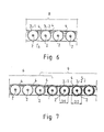
- Fig. 6 shows a part of the constant-speed section of the main conveyor 1.
- the two belt pulleys provided for each belt loop 4 and placed on different shafts 2 comprise a first belt pulley 3-1 and a second belt pulley 3-2.
- the transmission ratio i is determined by the ratio D1/D2 of the diameters of the first belt pulley 3-1 and the second belt pulley 3-2, the diameters being equal in this case.
- Fig. 7 shows a part of the connecting section 6 and of the branch conveyor 5.
- the deceleration section 9 begins some, distance before the end of the connecting section 6.
- the diameter D1 of the first belt pulley 3-1 is smaller than the diameter D2 of the second belt pulley 3-2.
- the transmission ratio between the first belt pulley 3-1 and the second belt pulley 3-2 is 1 > i ⁇ 0.9.
- the diameter D1 of the first belt pulley 3-1 is larger than the diameter D2 of the second belt pulley 3-2.
- the transmission ratio between the first belt pulley 3-1 and the second belt pulley 3-2 is 1 ⁇ i ⁇ 1.1.
Landscapes
- Escalators And Moving Walkways (AREA)
- Structure Of Belt Conveyors (AREA)
- Control Of Throttle Valves Provided In The Intake System Or In The Exhaust System (AREA)
- Organic Low-Molecular-Weight Compounds And Preparation Thereof (AREA)
- Rolls And Other Rotary Bodies (AREA)
Claims (21)
- Fahrsteigsystem, welcher einen Hauptförderer (1) zum Befördern von Passagieren enthält, welcher Hauptförderer folgende Merkmale umfasst- eine Anzahl an Achsen (2) die parallel zueinander in einem Abstand voneinander und senkrecht zur Transportrichtung des Hauptförderers (1) angeordnet sind, mit einer Anzahl Bandrollen (3) die nebeneinander mit jeder dieser Achsen verbunden sind,- eine Anzahl von zueinander parallelen Endlosbandschlaufen (4) welche die sich bewegende Förderfläche des Hauptförderers (1) bilden, wobei jeder dieser Bandschlaufen (1) über zwei Bandrollen auf zwei unterschiedlichen Achsen derart läuft, dass von jeweils zwei nebeneinanderliegenden Bandschlaufen auf der gleichen gemeinsamen Welle die über benachbarte Bandrollen geführt sind eine Bandschlaufe über eine Bandrolle auf einer der gemeinsamen Achse vorausgehenden Achse geführt ist, während die andere Bandschlaufe über eine Bandrolle auf der der gemeinsamen Achse folgenden Achse geführt ist,dadurch gekennzeichnet, dass der Fahrsteig einen Abzweigförderer (5) umfasst, welcher in einem Verbindungsbereich (6) von dem Hauptförderer (1) abzweigt, um es Fahrgästen zu erlauben, von dem Abzweigförderer (5) auf den Hauptförderer (1) zu gelangen, und/oder den Hauptförderer (1) über den Abzweigförderer (5) zu verlassen; wobei der Abzweigförderer (5) folgende Merkmale umfasst:- eine Anzahl von Achsen (2), die parallel zueinander in einem Abstand voneinander und senkrecht zur Transportrichtung des Förderers angeordnet sind, mit einer Anzahl an Bandrollen die nebeneinander mit jeder dieser Achsen verbunden sind, und- eine Anzahl von zueinander parallelen Endlosbandschlaufen (4) wobei jede der Bandschlaufen über zwei Bandrollen auf zwei unterschiedlichen Achsen derart geführt ist, dass von jeweils zwei nebeneinander befindlichen Bandschlaufen auf der gleichen gemeinsamen Achse die über benachbarte Bandrollen geführt sind, eine Bandschlaufe über eine Bandrolle auf einer der gemeinsamen Achse vorausgehenden Achse geführt ist, während die andere Bandschlaufe über eine Bandrolle auf einer der gemeinsamen Achse folgenden Achse geführt ist; unddass in dem Verbindungsabschnitt (6) der Abzweigförderer (5) und der Hauptförderer (1) wenigstens eine gemeinsame Achse (2) aufweisen.
- Fahrsteigsystem nach Anspruch 1, dadurch gekennzeichnet, dass der Verbindungsabschnitt (6) zwischen dem Hauptförderer (1) und dem Abzweigförderer (5) einen Aufweitungsbereich umfasst, in welchem der Hauptförderer und der Abzweigförderer mehrere gemeinsame Achsen (2) haben, deren Länge in Transportrichtung jeweils zueinander unterschiedlich ist und wechselt zwischen der Breite des Hauptförderers und der Gesamtbreite des Hauptförderers und Abzweigförderers.
- Fahrsteigsystem nach Anspruch 1 oder 2, dadurch gekennzeichnet, dass der Hauptförderer (1) folgende Merkmale enthält:- einen Beschleunigungsabschnitt (7) zur Beschleunigung der Passagiertransportgeschwindigkeit von einer im Wesentlichen geringen Anfangsgeschwindigkeit auf eine erhöhte Transportgeschwindigkeit- einen Abschnitt (8) konstanter Geschwindigkeit zum Fördern des Passagiers mit einer konstanten Transportgeschwindigkeit, wobei der Abzweigförderer (5) mit diesem Abschnitt verbunden ist, und- einen Abbremsabschnitt (9) zum Verringern der Passagiertransportgeschwindigkeit von der konstanten Transportgeschwindigkeit zu einer verringerten Endgeschwindigkeit.
- Fahrsteigsystem nach einem der Ansprüche 1-3, dadurch gekennzeichnet, dass das System einen Abzweigförderer (5) umfasst, der einen Eingang zu dem Hauptförderer (1) bildet; und das der Abzweigförderer (5) einen Beschleunigungsabschnitt (7) zum Beschleunigen der Passagiertransportgeschwindigkeit von einer im Wesentlichen geringen Anfangsgeschwindigkeit zu einer erhöhten Transportgeschwindigkeit entsprechend der Transportgeschwindigkeit des Hauptförderers an dem Punkt enthält, wo der Abzweigförderer (5) mit dem Hauptförderer (1) verbunden ist.
- Fahrsteigsystem nach einem der Ansprüche 1-4, dadurch gekennzeichnet, dass das System einen Abzweigförderer (5) umfasst, der einen Ausgang von dem Hauptförderer (1) bildet; und dass der Abzweigförderer (5) einen Bremsabschnitt (9) zum Verringern der Passagiertransportgeschwindigkeit von der Transportgeschwindigkeit des Hauptförderers (1) auf eine verringerte Endgeschwindigkeit enthält.
- Fahrsteigsystem nach einem der Ansprüche 1-4, dadurch gekennzeichnet, dass das System einen Abzweigförderer (5) enthält, der einen Abschnitt (8) konstanter Geschwindigkeit enthält, um den Passagier mit einer konstanten Geschwindigkeit zu befördern.
- Fahrsteigsystem nach einem der Ansprüche 1-6, dadurch gekennzeichnet, dass das System wenigstens zwei Hauptförderer (1) enthält, deren Abschnitte (8) konstanter Geschwindigkeit sich auf unterschiedlichen Höhen schneiden; dass die Transportgeschwindigkeit des Abzweigförderers (5) im Wesentlichen die gleiche ist wie die konstante Transportgeschwindigkeit der Abschnitte (8) konstanter Geschwindigkeit der Hauptförderer (1); und dass der Abzweigförderer (5) die Abschnitte (8) konstanter Geschwindigkeit der Hauptförderer (1) verbindet, um es Passagieren zu erlauben, von einem Hauptförderer auf einen anderen Hauptförderer zu gelangen.
- Fahrsteigsystem nach einem der Ansprüche 1-7, dadurch gekennzeichnet, dass das Fahrsteigsystem ein öffentliches Transportnetzwerk bildet, das eine Anzahl von sich gegenseitig schneidenden Hauptförderern (1) auf unterschiedlichen Höhen und eine Anzahl von Abzweigförderern (5) umfasst, die von diesem abzweigen.
- Fahrsteigsystem nach einem der Ansprüche 1-8, dadurch gekennzeichnet, dass die zwei Bandrollen, die für jede Bandschlaufe (4) vorgesehen und auf unterschiedlichen Achsen (2) angeordnet sind, eine erste Bandrolle (3-1) und eine zweite Bandrolle (3-2) enthalten; und das in den Abbrems- und Beschleunigungsabschnitten (7, 9) ein Übersetzungsverhältnis (i) zwischen der ersten Bandrolle (3-1) und der zweiten Bandrolle (3-2) existiert.
- Fahrsteigsystem nach Anspruch 9, dadurch gekennzeichnet, dass das Übersetzungsverhältnis (i) bestimmt wird durch das Verhältnis (D1/D2) der Durchmesser der ersten Bandrolle (3-1) und der zweiten Bandrolle (3-2).
- Fahrsteigsystem nach Anspruch 10, dadurch gekennzeichnet, dass in dem Beschleunigungsabschnitt (7) der Durchmesser (D1) der ersten Bandrolle (3-1) größer ist als der Durchmesser (D2) der zweiten Bandrolle (3-2).
- Fahrsteigsystem nach Anspruch 10 oder 11, dadurch gekennzeichnet, dass in dem Abbremsabschnitt (9) der Durchmesser (D1) der ersten Bandrolle (3-1) geringer ist als der Durchmesser (D2) der zweiten Bandrolle (3-2).
- Fahrsteigsystem nach einem der Ansprüche 9-12, dadurch gekennzeichnet, dass die Bandschlaufen (4) gezahnte Bänder sind; dass in dem Brems/Beschleunigungsabschnitt die erste Bandrolle (3-1) und die zweite Bandrolle (3-2) gezahnte Bandrollen sind, die eine unterschiedliche Anzahl von Zähnen (Z1, Z2) umfassen, wobei das Übersetzungsverhältnis zwischen der ersten Bandrolle und der zweiten Bandrolle somit festgelegt ist durch das Verhältnis (Z1/Z2) der Anzahl an Zähnen auf den Bandrollen.
- Fahrsteigsystem nach einem der Ansprüche 9-13, dadurch gekennzeichnet, dass in dem Beschleunigungsabschnitt (7) das Übersetzungsverhältnis (i) zwischen der ersten Bandrolle (3-1) und der zweiten Bandrolle (3-2) wenigstens 1 und geringer als 1,1 ist.
- Fahrsteigsystem nach einem der Ansprüche 9-14, dadurch gekennzeichnet, dass in dem Bremsabschnitt (9) das Übersetzungsverhältnis zwischen der ersten Bandrolle (3-1) und der zweiten Bandrolle (3-2) höchstens 1 und größer als 0,9 ist.
- Fahrsteigsystem nach einem der Ansprüche 1-15, dadurch gekennzeichnet, dass die Anfangsgeschwindigkeit und die Endgeschwindigkeit des Fahrsteigs in der Größenordnung von ungefähr von 0,5 bis 0,7 m/s liegen.
- Fahrsteigsystem nach einem der Ansprüche 1-16, dadurch gekennzeichnet, dass die Transportgeschwindigkeit in dem Abschnitt (8) konstanter Geschwindigkeit in der Größenordnung von 2,5 - 7 m/s und vorzugsweise um die 3 - 6 m/s und insbesondere um die 5 m/s liegt.
- Fahrsteigsystem nach einem der Ansprüche 1 - 17, dadurch gekennzeichnet, dass die Änderung der Transportgeschwindigkeit in dem Beschleunigungsabschnitt so angepasst ist, dass die durchschnittliche Beschleunigung, die von den Passagieren wahrgenommen wird, in der Größenordnung von 0,3 m/s2 liegt.
- Fahrsteigsystem nach einem der Ansprüche 1 - 18, dadurch gekennzeichnet, dass die Änderung in der Transportgeschwindigkeit in dem Bremsabschnitt so angepasst ist, dass die durchschnittliche Abbremsung, die von den Passagieren wahrgenommen wird, in der Größenordnung von 0,3 m/s2 liegt.
- Fahrsteigsystem nach einem der Ansprüche 1-19, dadurch gekennzeichnet, dass das Fahrsteigsystem aus Förderern besteht, die konzipiert sind, um auf einer festen Basis montiert zu werden, wie z. B. einen Boden, dem Grund oder irgendeinem anderen Träger.
- Fahrsteigsystem nach einem der vorhergehenden Ansprüche, dadurch gekennzeichnet, dass das Fahrsteigsystem wenigstens eine durch einen Antriebsapparat angetriebene Achse und eine Anzahl von Achsen hat, auf welchen die Bandrollen die für die Rotation benötigte Antriebskraft über die in der Förderebene enthaltenen Bandschlaufen von den Bandrollen erhalten, die auf der vom Antriebapparat angetrieben Achse angeordnet sind.
Applications Claiming Priority (2)
| Application Number | Priority Date | Filing Date | Title |
|---|---|---|---|
| FI20040907A FI20040907L (fi) | 2004-06-30 | 2004-06-30 | Liukukäytäväjärjestelmä |
| PCT/FI2005/000206 WO2006003236A2 (en) | 2004-06-30 | 2005-05-04 | Travelator system |
Publications (2)
| Publication Number | Publication Date |
|---|---|
| EP1761452A2 EP1761452A2 (de) | 2007-03-14 |
| EP1761452B1 true EP1761452B1 (de) | 2008-05-28 |
Family
ID=32524573
Family Applications (1)
| Application Number | Title | Priority Date | Filing Date |
|---|---|---|---|
| EP05737682A Expired - Lifetime EP1761452B1 (de) | 2004-06-30 | 2005-05-04 | Fahrsteiganlage |
Country Status (11)
| Country | Link |
|---|---|
| US (1) | US7832543B2 (de) |
| EP (1) | EP1761452B1 (de) |
| JP (1) | JP2008504192A (de) |
| CN (1) | CN100548856C (de) |
| AT (1) | ATE396950T1 (de) |
| DE (1) | DE602005007226D1 (de) |
| ES (1) | ES2304013T3 (de) |
| FI (1) | FI20040907L (de) |
| MY (1) | MY136734A (de) |
| TW (1) | TW200606086A (de) |
| WO (1) | WO2006003236A2 (de) |
Families Citing this family (6)
| Publication number | Priority date | Publication date | Assignee | Title |
|---|---|---|---|---|
| JP2011136826A (ja) * | 2009-12-29 | 2011-07-14 | Toshiba Elevator Co Ltd | 乗客コンベア |
| CN102649527B (zh) * | 2011-02-25 | 2015-09-02 | 咸宁市农机化技术鉴定推广中心站 | 自动输送道路车 |
| JP5932757B2 (ja) * | 2013-11-15 | 2016-06-08 | 株式会社フィルテック | 流体熱交換装置 |
| CN106516675A (zh) * | 2016-12-20 | 2017-03-22 | 信宜市恒大机械科技有限公司 | 可调砖块摆放密度的输送带 |
| CN106738218A (zh) * | 2016-12-20 | 2017-05-31 | 信宜市恒大机械科技有限公司 | 一种自动化制砖生产线 |
| ES2910778B2 (es) * | 2020-11-13 | 2022-11-11 | De Antonio Carlos Hernandez | Alfombra mecanica para lineas de transporte |
Family Cites Families (16)
| Publication number | Priority date | Publication date | Assignee | Title |
|---|---|---|---|---|
| US1412969A (en) * | 1918-08-14 | 1922-04-18 | Sachs Philip | System of transportation |
| FR549153A (fr) | 1922-03-21 | 1923-02-03 | Plateforme mobile transporteuse | |
| US1689201A (en) * | 1922-06-17 | 1928-10-30 | Halter Georges | Conveyer operated at accelerated speed |
| FR556796A (fr) | 1922-09-13 | 1923-07-26 | Plate-forme mobile transporteuse | |
| US1665483A (en) * | 1926-12-13 | 1928-04-10 | Herman E Taylor | Transportation system |
| US2769522A (en) * | 1954-02-03 | 1956-11-06 | Fred B Pfeiffer | Conveyor and stretching means |
| FR1560309A (de) * | 1967-11-20 | 1969-03-21 | ||
| FR1591121A (de) * | 1968-10-15 | 1970-04-27 | ||
| FR2076180A1 (fr) * | 1970-01-05 | 1971-10-15 | Patin Pierre | Perfectionnement apporté aux roulements anti-friction et ses applications, notamment en convoyage. |
| US4232776A (en) * | 1978-01-05 | 1980-11-11 | Dean Research Corporation | Accelerating walkway |
| US5341915A (en) * | 1992-11-06 | 1994-08-30 | Kliklok Corporation | Article phasing, transfer and squaring system for packaging line |
| JP2757794B2 (ja) | 1994-11-02 | 1998-05-25 | 村田機械株式会社 | コンベア装置 |
| CA2449963A1 (en) * | 2001-06-07 | 2002-12-12 | David W. Zeitler | Tiered control architecture for material handling |
| JP2003020181A (ja) | 2001-07-10 | 2003-01-21 | Mitsubishi Electric Corp | 可変速式動く歩道 |
| JP2003327316A (ja) * | 2002-05-13 | 2003-11-19 | Kawasaki Heavy Ind Ltd | 速度可変ベルトコンベア装置 |
| FI117173B (fi) | 2003-11-28 | 2006-07-14 | Kone Corp | Liukukäytävä |
-
2004
- 2004-06-30 FI FI20040907A patent/FI20040907L/fi not_active Application Discontinuation
-
2005
- 2005-05-04 US US11/630,359 patent/US7832543B2/en not_active Expired - Fee Related
- 2005-05-04 ES ES05737682T patent/ES2304013T3/es not_active Expired - Lifetime
- 2005-05-04 AT AT05737682T patent/ATE396950T1/de not_active IP Right Cessation
- 2005-05-04 DE DE602005007226T patent/DE602005007226D1/de not_active Expired - Lifetime
- 2005-05-04 WO PCT/FI2005/000206 patent/WO2006003236A2/en not_active Ceased
- 2005-05-04 JP JP2007518624A patent/JP2008504192A/ja not_active Abandoned
- 2005-05-04 CN CNB2005800216838A patent/CN100548856C/zh not_active Expired - Fee Related
- 2005-05-04 EP EP05737682A patent/EP1761452B1/de not_active Expired - Lifetime
- 2005-05-25 TW TW094117036A patent/TW200606086A/zh unknown
- 2005-05-27 MY MYPI20052435A patent/MY136734A/en unknown
Also Published As
| Publication number | Publication date |
|---|---|
| TW200606086A (en) | 2006-02-16 |
| US7832543B2 (en) | 2010-11-16 |
| MY136734A (en) | 2008-11-28 |
| FI20040907A7 (fi) | 2005-12-31 |
| WO2006003236A2 (en) | 2006-01-12 |
| WO2006003236A3 (en) | 2006-06-15 |
| FI20040907A0 (fi) | 2004-06-30 |
| ES2304013T3 (es) | 2008-09-01 |
| EP1761452A2 (de) | 2007-03-14 |
| JP2008504192A (ja) | 2008-02-14 |
| DE602005007226D1 (de) | 2008-07-10 |
| FI20040907L (fi) | 2005-12-31 |
| US20080035447A1 (en) | 2008-02-14 |
| CN100548856C (zh) | 2009-10-14 |
| CN1976860A (zh) | 2007-06-06 |
| ATE396950T1 (de) | 2008-06-15 |
Similar Documents
| Publication | Publication Date | Title |
|---|---|---|
| CN100594172C (zh) | 用于在活动人行道上输送旅客的方法及活动人行道 | |
| US20100282121A1 (en) | Cable railway with entering/exiting aid | |
| JPH04287757A (ja) | 二つの連続した区分を有する頭上ケーブル輸送設備 | |
| US4843970A (en) | Overhead cable transport installation containing a transfer section between a disembarking section and an embarking section | |
| JP2007512201A5 (de) | ||
| EP1761452B1 (de) | Fahrsteiganlage | |
| US5690031A (en) | Aerial cableway having a movement take up module | |
| EP1153873B1 (de) | Rollsteig mit variabler geschwindigkeit und verfahren zu seinem entwurf | |
| HK1100138A (en) | Travelator system | |
| JPH05254426A (ja) | 自動循環式索道搬器の一時停止運行方法 | |
| GB2230753A (en) | Passenger conveyor apparatus | |
| JPH106977A (ja) | 人および/または貨物搬送装置 | |
| JP3456325B2 (ja) | 動く歩道の移動手摺 | |
| RU2384439C2 (ru) | Способ модернизации и способ эксплуатации семенова ю.м., повышающие производительность, надежность, безопасность и удобство пользования пассажирскими кресельными и буксировочными канатными дорогами с подвижным составом, закрепленным на канате постоянно, "посадочное устройство" для их осуществления (варианты), "разгонно-посадочное устройство" для их осуществления (варианты) и "опорно-тяговый поворотный рычаг" для посадочного устройства | |
| JPH11286383A (ja) | 可変速型乗客コンベヤの手すり装置 | |
| JP2000327250A (ja) | 可変速型乗客コンベヤの手すり装置 | |
| ITBZ950061A1 (it) | Tappeto mobile per agevolare l'accesso ad una seggiovia realizzato con catene per trasportatori e traverse rigide. | |
| JPH0110297Y2 (de) | ||
| JPH0977444A (ja) | 可変速式動く歩道 | |
| JPH10252836A (ja) | 可変型運搬装置 | |
| CN2075184U (zh) | 输送装置变速系统 | |
| JPH11286382A (ja) | 可変速型乗客コンベヤ | |
| JPH09142765A (ja) | 加速および減速ゾーンを有する動く歩道 | |
| JP2000211867A (ja) | 可変速式乗客コンベア | |
| JPH1059668A (ja) | 可変速型乗客コンベヤ |
Legal Events
| Date | Code | Title | Description |
|---|---|---|---|
| PUAI | Public reference made under article 153(3) epc to a published international application that has entered the european phase |
Free format text: ORIGINAL CODE: 0009012 |
|
| 17P | Request for examination filed |
Effective date: 20061229 |
|
| AK | Designated contracting states |
Kind code of ref document: A2 Designated state(s): AT BE BG CH CY CZ DE DK EE ES FI FR GB GR HU IE IS IT LI LT LU MC NL PL PT RO SE SI SK TR |
|
| DAX | Request for extension of the european patent (deleted) | ||
| GRAP | Despatch of communication of intention to grant a patent |
Free format text: ORIGINAL CODE: EPIDOSNIGR1 |
|
| GRAS | Grant fee paid |
Free format text: ORIGINAL CODE: EPIDOSNIGR3 |
|
| GRAA | (expected) grant |
Free format text: ORIGINAL CODE: 0009210 |
|
| AK | Designated contracting states |
Kind code of ref document: B1 Designated state(s): AT BE BG CH CY CZ DE DK EE ES FI FR GB GR HU IE IS IT LI LT LU MC NL PL PT RO SE SI SK TR |
|
| REG | Reference to a national code |
Ref country code: GB Ref legal event code: FG4D |
|
| REG | Reference to a national code |
Ref country code: CH Ref legal event code: EP |
|
| REF | Corresponds to: |
Ref document number: 602005007226 Country of ref document: DE Date of ref document: 20080710 Kind code of ref document: P |
|
| REG | Reference to a national code |
Ref country code: IE Ref legal event code: FG4D |
|
| REG | Reference to a national code |
Ref country code: ES Ref legal event code: FG2A Ref document number: 2304013 Country of ref document: ES Kind code of ref document: T3 |
|
| PG25 | Lapsed in a contracting state [announced via postgrant information from national office to epo] |
Ref country code: SI Free format text: LAPSE BECAUSE OF FAILURE TO SUBMIT A TRANSLATION OF THE DESCRIPTION OR TO PAY THE FEE WITHIN THE PRESCRIBED TIME-LIMIT Effective date: 20080528 |
|
| PG25 | Lapsed in a contracting state [announced via postgrant information from national office to epo] |
Ref country code: FI Free format text: LAPSE BECAUSE OF FAILURE TO SUBMIT A TRANSLATION OF THE DESCRIPTION OR TO PAY THE FEE WITHIN THE PRESCRIBED TIME-LIMIT Effective date: 20080528 |
|
| PG25 | Lapsed in a contracting state [announced via postgrant information from national office to epo] |
Ref country code: AT Free format text: LAPSE BECAUSE OF FAILURE TO SUBMIT A TRANSLATION OF THE DESCRIPTION OR TO PAY THE FEE WITHIN THE PRESCRIBED TIME-LIMIT Effective date: 20080528 Ref country code: NL Free format text: LAPSE BECAUSE OF FAILURE TO SUBMIT A TRANSLATION OF THE DESCRIPTION OR TO PAY THE FEE WITHIN THE PRESCRIBED TIME-LIMIT Effective date: 20080528 |
|
| NLV1 | Nl: lapsed or annulled due to failure to fulfill the requirements of art. 29p and 29m of the patents act | ||
| PG25 | Lapsed in a contracting state [announced via postgrant information from national office to epo] |
Ref country code: IS Free format text: LAPSE BECAUSE OF FAILURE TO SUBMIT A TRANSLATION OF THE DESCRIPTION OR TO PAY THE FEE WITHIN THE PRESCRIBED TIME-LIMIT Effective date: 20080928 |
|
| PG25 | Lapsed in a contracting state [announced via postgrant information from national office to epo] |
Ref country code: SE Free format text: LAPSE BECAUSE OF FAILURE TO SUBMIT A TRANSLATION OF THE DESCRIPTION OR TO PAY THE FEE WITHIN THE PRESCRIBED TIME-LIMIT Effective date: 20080828 Ref country code: LT Free format text: LAPSE BECAUSE OF FAILURE TO SUBMIT A TRANSLATION OF THE DESCRIPTION OR TO PAY THE FEE WITHIN THE PRESCRIBED TIME-LIMIT Effective date: 20080528 Ref country code: DK Free format text: LAPSE BECAUSE OF FAILURE TO SUBMIT A TRANSLATION OF THE DESCRIPTION OR TO PAY THE FEE WITHIN THE PRESCRIBED TIME-LIMIT Effective date: 20080528 Ref country code: CZ Free format text: LAPSE BECAUSE OF FAILURE TO SUBMIT A TRANSLATION OF THE DESCRIPTION OR TO PAY THE FEE WITHIN THE PRESCRIBED TIME-LIMIT Effective date: 20080528 |
|
| PG25 | Lapsed in a contracting state [announced via postgrant information from national office to epo] |
Ref country code: PT Free format text: LAPSE BECAUSE OF FAILURE TO SUBMIT A TRANSLATION OF THE DESCRIPTION OR TO PAY THE FEE WITHIN THE PRESCRIBED TIME-LIMIT Effective date: 20081028 Ref country code: SK Free format text: LAPSE BECAUSE OF FAILURE TO SUBMIT A TRANSLATION OF THE DESCRIPTION OR TO PAY THE FEE WITHIN THE PRESCRIBED TIME-LIMIT Effective date: 20080528 Ref country code: RO Free format text: LAPSE BECAUSE OF FAILURE TO SUBMIT A TRANSLATION OF THE DESCRIPTION OR TO PAY THE FEE WITHIN THE PRESCRIBED TIME-LIMIT Effective date: 20080528 Ref country code: BE Free format text: LAPSE BECAUSE OF FAILURE TO SUBMIT A TRANSLATION OF THE DESCRIPTION OR TO PAY THE FEE WITHIN THE PRESCRIBED TIME-LIMIT Effective date: 20080528 |
|
| PLBE | No opposition filed within time limit |
Free format text: ORIGINAL CODE: 0009261 |
|
| STAA | Information on the status of an ep patent application or granted ep patent |
Free format text: STATUS: NO OPPOSITION FILED WITHIN TIME LIMIT |
|
| PG25 | Lapsed in a contracting state [announced via postgrant information from national office to epo] |
Ref country code: EE Free format text: LAPSE BECAUSE OF FAILURE TO SUBMIT A TRANSLATION OF THE DESCRIPTION OR TO PAY THE FEE WITHIN THE PRESCRIBED TIME-LIMIT Effective date: 20080528 Ref country code: BG Free format text: LAPSE BECAUSE OF FAILURE TO SUBMIT A TRANSLATION OF THE DESCRIPTION OR TO PAY THE FEE WITHIN THE PRESCRIBED TIME-LIMIT Effective date: 20080828 |
|
| 26N | No opposition filed |
Effective date: 20090303 |
|
| PG25 | Lapsed in a contracting state [announced via postgrant information from national office to epo] |
Ref country code: MC Free format text: LAPSE BECAUSE OF NON-PAYMENT OF DUE FEES Effective date: 20090531 |
|
| REG | Reference to a national code |
Ref country code: CH Ref legal event code: PL |
|
| PG25 | Lapsed in a contracting state [announced via postgrant information from national office to epo] |
Ref country code: CH Free format text: LAPSE BECAUSE OF NON-PAYMENT OF DUE FEES Effective date: 20090531 Ref country code: LI Free format text: LAPSE BECAUSE OF NON-PAYMENT OF DUE FEES Effective date: 20090531 |
|
| REG | Reference to a national code |
Ref country code: IE Ref legal event code: MM4A |
|
| PG25 | Lapsed in a contracting state [announced via postgrant information from national office to epo] |
Ref country code: IE Free format text: LAPSE BECAUSE OF NON-PAYMENT OF DUE FEES Effective date: 20090504 |
|
| PG25 | Lapsed in a contracting state [announced via postgrant information from national office to epo] |
Ref country code: PL Free format text: LAPSE BECAUSE OF FAILURE TO SUBMIT A TRANSLATION OF THE DESCRIPTION OR TO PAY THE FEE WITHIN THE PRESCRIBED TIME-LIMIT Effective date: 20080528 |
|
| PG25 | Lapsed in a contracting state [announced via postgrant information from national office to epo] |
Ref country code: GR Free format text: LAPSE BECAUSE OF FAILURE TO SUBMIT A TRANSLATION OF THE DESCRIPTION OR TO PAY THE FEE WITHIN THE PRESCRIBED TIME-LIMIT Effective date: 20080829 |
|
| PG25 | Lapsed in a contracting state [announced via postgrant information from national office to epo] |
Ref country code: LU Free format text: LAPSE BECAUSE OF NON-PAYMENT OF DUE FEES Effective date: 20090504 |
|
| PG25 | Lapsed in a contracting state [announced via postgrant information from national office to epo] |
Ref country code: HU Free format text: LAPSE BECAUSE OF FAILURE TO SUBMIT A TRANSLATION OF THE DESCRIPTION OR TO PAY THE FEE WITHIN THE PRESCRIBED TIME-LIMIT Effective date: 20081129 |
|
| PG25 | Lapsed in a contracting state [announced via postgrant information from national office to epo] |
Ref country code: TR Free format text: LAPSE BECAUSE OF FAILURE TO SUBMIT A TRANSLATION OF THE DESCRIPTION OR TO PAY THE FEE WITHIN THE PRESCRIBED TIME-LIMIT Effective date: 20080528 |
|
| PG25 | Lapsed in a contracting state [announced via postgrant information from national office to epo] |
Ref country code: CY Free format text: LAPSE BECAUSE OF FAILURE TO SUBMIT A TRANSLATION OF THE DESCRIPTION OR TO PAY THE FEE WITHIN THE PRESCRIBED TIME-LIMIT Effective date: 20080528 |
|
| PGFP | Annual fee paid to national office [announced via postgrant information from national office to epo] |
Ref country code: DE Payment date: 20120523 Year of fee payment: 8 |
|
| PGFP | Annual fee paid to national office [announced via postgrant information from national office to epo] |
Ref country code: GB Payment date: 20120522 Year of fee payment: 8 Ref country code: FR Payment date: 20120601 Year of fee payment: 8 |
|
| PGFP | Annual fee paid to national office [announced via postgrant information from national office to epo] |
Ref country code: IT Payment date: 20120528 Year of fee payment: 8 |
|
| PGFP | Annual fee paid to national office [announced via postgrant information from national office to epo] |
Ref country code: ES Payment date: 20120521 Year of fee payment: 8 |
|
| GBPC | Gb: european patent ceased through non-payment of renewal fee |
Effective date: 20130504 |
|
| PG25 | Lapsed in a contracting state [announced via postgrant information from national office to epo] |
Ref country code: DE Free format text: LAPSE BECAUSE OF NON-PAYMENT OF DUE FEES Effective date: 20131203 |
|
| REG | Reference to a national code |
Ref country code: DE Ref legal event code: R119 Ref document number: 602005007226 Country of ref document: DE Effective date: 20131203 |
|
| PG25 | Lapsed in a contracting state [announced via postgrant information from national office to epo] |
Ref country code: IT Free format text: LAPSE BECAUSE OF NON-PAYMENT OF DUE FEES Effective date: 20130504 |
|
| REG | Reference to a national code |
Ref country code: FR Ref legal event code: ST Effective date: 20140131 |
|
| PG25 | Lapsed in a contracting state [announced via postgrant information from national office to epo] |
Ref country code: GB Free format text: LAPSE BECAUSE OF NON-PAYMENT OF DUE FEES Effective date: 20130504 |
|
| PG25 | Lapsed in a contracting state [announced via postgrant information from national office to epo] |
Ref country code: FR Free format text: LAPSE BECAUSE OF NON-PAYMENT OF DUE FEES Effective date: 20130531 |
|
| REG | Reference to a national code |
Ref country code: ES Ref legal event code: FD2A Effective date: 20140606 |
|
| PG25 | Lapsed in a contracting state [announced via postgrant information from national office to epo] |
Ref country code: ES Free format text: LAPSE BECAUSE OF NON-PAYMENT OF DUE FEES Effective date: 20130505 |