EP1928721B1 - Seilentgleisungsschutzvorrichtung für trag-/zugseile von seilbahnanlagen - Google Patents
Seilentgleisungsschutzvorrichtung für trag-/zugseile von seilbahnanlagen Download PDFInfo
- Publication number
- EP1928721B1 EP1928721B1 EP06795475A EP06795475A EP1928721B1 EP 1928721 B1 EP1928721 B1 EP 1928721B1 EP 06795475 A EP06795475 A EP 06795475A EP 06795475 A EP06795475 A EP 06795475A EP 1928721 B1 EP1928721 B1 EP 1928721B1
- Authority
- EP
- European Patent Office
- Prior art keywords
- cable
- clamp
- derailing prevention
- prevention apparatus
- support
- Prior art date
- Legal status (The legal status is an assumption and is not a legal conclusion. Google has not performed a legal analysis and makes no representation as to the accuracy of the status listed.)
- Active
Links
Images


Classifications
-
- B—PERFORMING OPERATIONS; TRANSPORTING
- B61—RAILWAYS
- B61B—RAILWAY SYSTEMS; EQUIPMENT THEREFOR NOT OTHERWISE PROVIDED FOR
- B61B12/00—Component parts, details or accessories not provided for in groups B61B7/00 - B61B11/00
- B61B12/06—Safety devices or measures against cable fracture
Definitions
- the present invention relates to a Seilentgleisungsschutzvorraum for support / traction ropes of cable car systems according to the preamble of claim 1.
- a device for catching a hoisting rope of a cableway or a tow lift is known, which is derailed from the rope support rollers of a support, with at least one arranged in the region of the rope support rollers movable rope support, when exceeding a responsive to a critical rope position reporting device for switching off the cable car system.
- a critical rope position reporting device for switching off the cable car system.
- this described device is not able to solve the problem described with certainty because the rope course is not limited within limits that allows the rope to be gripped by the clamp.
- the described device is also designed to catch an already clamped rope by means of the clamp to stop the system with derailed rope via a signaling device.
- the object of the present invention is to avoid the problems of the prior art and to propose a cable derailment protection device at the exit of a station, which in the clamping area ensures the position of the cable and the gripping of the rope by the terminal and stops the system with coupled terminals in case of derailment ,
- Another object is the cable derailment device assign a forced operation device such that the gripping of the clamp on the rope is enforced.
- an alignment device of the cable is proposed in front of the coupling region of an automatic coupling clamp on a cable, this is guided in its running direction in order to arrive centered on the rollers on the first roller battery in order to place the cable between the alignment device and the first roller battery in such a way that it is within the limits imposed by the mouth opening of the clamp to be coupled.
- At least one guide holder is arranged, which invites the rope to go in the direction of the target line for the clutch.
- an upper shoe-type rope catching device is provided, always to keep the rope in the direction of a line which is suitable to center the rope on the mouth opening of the terminal to be coupled.
- a positive guidance device which forces the clamp to travel above the rope in the presence of snow accumulation on the guide rail of the pulley carrying the clamp.
- FIG. 1 is indicated by the reference numeral 1 a total of a cable car system in the area of the output of a station.
- the system comprises in a known manner a support / traction cable 2, a plurality of rollers 3 at the exit of the station facing a dome rail of known and not shown type, a clamp 4 on which the driving means, not shown, is suspended, and at least a rope 2 carrying roller 5 with coupled terminal 4 and a supporting or holding down roller battery 6 according to the course of the rope. 2
- the roller battery 6 is provided with an upper, outer cable shoe 7 and with an inner, upper protection 8 when the support of the roller battery 6 acts as a hold-down support in which the rope presses from below onto the roller battery.
- the roller battery 6, however, is provided with a lower, outer rope-catching shoe 9 and with a lower, inner protection 10, when the support of the roller battery 6 acts as a support post, in which the rope presses from above onto the roller battery 6.
- a derailment on the roller battery 6 could already cause excessive deflection of the cable in the coupling area, in which the terminal 4 is not yet able to grasp the rope 2, since the opening of its mouth is not able to grip the rope, with the consequent risk that the rope resource crashes.
- an alignment device 11 is provided in front of the coupling region of the terminal 4 on the cable 2, in front of the coupling rail, which is capable of limiting the derailment of the roller battery 6 deflection of the cable 2 such that the rope 2 is always located within the mouth opening 12 of the clamp.
- the alignment device 11 is formed by a holder 13 in which a bore 14 is excluded, with larger dimensions than the diameter of the rope 2, which depend on the distance from the intended clamping position.
- the alignment device 11 is associated with at least one cable trap holder 15 for supporting the cable 2, on which the clamp 4 is already coupled.
- the rope catcher 15 has a concave surface to direct the rope 2 towards the center of the concavity.
- an upper cable clip 16 is assigned, which limits the rope 2 above in its deflection.
- the alignment device 11 is associated with a signaling system that stops the cable car installation as soon as the cable 2 touches the bore 14, while still allowing the terminal to be attached, but with the cableway installation being stopped with the terminal already attached, and therefore without the risk of the driving means together with the passengers fall down.
- a positive guide means 17 is provided instead of a holder 15. This is attached to a support structure 18 of the coupling rail 19 of the support roller 20 of the terminal 2.
- the positive guide device 17 is mounted on a bracket 21 which is secured by means of bolts 22 on the support structure 18. From the bracket 21, a support bracket 23 extends upward to which a linkage 24 a fork 25 is attached. This has a lower arm 26, the free end is formed as a support 27 for the cable 2. The fork 25 also has an upper arm 28 which terminates with a lug 29 to come into contact with the body of the clamp 2.
- an adjustable distance 30 is set to let pass the entirety of the terminal 4 and the rope 2 with above the support 27 freely passing rope 2 at a Anklemmung that is done normally between the clamp and rope.
- the clamp is raised and with the same fork 25, wherein the rope 2 is raised to the support 27 such that the terminal 4 still surrounds the rope.
- the maximum deflection 31 is drawn down when the fork 25 abuts against the support 27, wherein it is clear that so the terminal is aligned to a complete clamping of the rope.
Landscapes
- Engineering & Computer Science (AREA)
- Transportation (AREA)
- Mechanical Engineering (AREA)
- Electric Cable Installation (AREA)
- Road Signs Or Road Markings (AREA)
- Train Traffic Observation, Control, And Security (AREA)
- Emergency Lowering Means (AREA)
- Ropes Or Cables (AREA)
- Laying Of Electric Cables Or Lines Outside (AREA)
- Refuge Islands, Traffic Blockers, Or Guard Fence (AREA)
- Platform Screen Doors And Railroad Systems (AREA)
- Rotary Pumps (AREA)
- Earth Drilling (AREA)
Description
- Die vorliegende Erfindung bezieht sich auf eine Seilentgleisungsschutzvorrichtung für Trag-/Zugseile von Seilbahnanlagen gemäß dem Oberbegriff des Anspruchs 1.
- Am Ausgang aus den Stationen von Seilbahnanlagen besteht die Gefahr, dass die Klemme, an der das Fahrbetriebsmittel aufgehängt ist, wegen einer Entgleisung des Seils nach dem Klemmbereich nicht mit dem Seil gekoppelt wird. Je nachdem, ob die Rollenbatterie niederhaltend oder tragend ist, könnte das Seil nach oben oder nach unten abgelenkt werden, um von einer Seilfangeinrichtung gefangen zu werden und gleichzeitig seine vorgegeben Position im Klemmbereich am Ausgang der Station zu verlassen.
- Aus der internationalen Anmeldung
WO 2004/085221 ist eine Vorrichtung zum Auffangen eines Förderseiles einer Seilschwebebahn oder eines Schleppliftes bekannt, das aus den Seiltragrollen einer Stütze entgleist ist, mit mindestens einer im Bereich der Seiltragrollen angeordneten beweglichen Seilfangeinrichtung, einer bei Überschreitung einer auf eine kritischen Seillage ansprechenden Meldeeinrichtung zur Abschaltung der Seilbahnanlage. Bei Überschreitung einer vorbestimmten kritischen Seillage ist die Seilfangeinrichtung aus ihrer eingezogenen Ruheposition in eine Seilfangposition bewegbar. - Diese beschriebene Vorrichtung ist jedoch nicht imstande, mit Sicherheit das beschriebene Problem zu lösen, da nicht der Seilverlauf innerhalb Grenzen begrenzt wird, die das Ergreifen des Seils seitens der Klemme erlaubt. Die beschriebene Vorrichtung ist überdies ausgelegt, um ein schon angeklemmtes Seil mittels der Klemme aufzufangen, um die Anlage mit entgleistem Seil über eine Meldeeinrichtung anzuhalten.
- Den nächstliegenden Stand der Technik gemäss den Merkmalen des Oberbegriffes des unabhängigen Anspruchs 1 bildet
EP-A-0 517 622 . - Die Aufgabe der vorliegenden Erfindung ist die Probleme des bekannten Standes der Technik zu vermeiden und eine Seilentgleisungsschutzvorrichtung am Ausgang einer Station vorzuschlagen, die im Klemmbereich die Position des Seils und das Ergreifen des Seils seitens der Klemme sicherstellt und die Anlage mit angekoppelten Klemmen bei einer Entgleisung anhält.
- Eine weitere Aufgabe ist der Seilentgleisungsvorrichtung eine Zwangsführungseinrichtung derart zuzuordnen, dass das Ergreifen der Klemme am Seil erzwungen wird.
- Diese und weitere Aufgaben werden durch eine Seilentgleisungsschutzvorrichtung in Seilbahnanlagen gemäß dem kennzeichnenden Teil des Anspruchs 1 gelöst.
- Wird vor dem Kupplungsbereich einer selbsttätigen Kupplungsklemme an einem Seil eine Ausrichteinrichtung des Seils vorgeschlagen, wird dieses in seiner Laufrichtung geführt, um an der ersten Rollenbatterie möglichst auf die Rollen zentriert anzukommen, um das Seil zwischen der Ausrichteinrichtung und der ersten Rollenbatterie derart zu legen, dass es sich innerhalb den von der Maulöffnung der zu kuppelnden Klemme auferlegten Grenzen befindet.
- In einer Ausführungsform ist zur noch besseren Ausrichtung des Seils in Richtung des Klemmmauls zwischen dem Kupplungsbereich der Klemme und der Rollenbatterie mindestens eine Führungshalterung angeordnet, die das Seil dazu einlädt, sich in Richtung der Solllinie für die Kupplung zu begeben.
- In einer weiteren Ausführungsform ist außer dieser Halterung auch eine obere schuhartige Seilfangvorrichtung vorgesehen, immer um das Seil in Richtung einer Linie zu halten, die geeignet ist, das Seil auf die Maulöffnung der zu kuppelnden Klemme zu zentrieren.
- In einer Variante, anstatt eine einfachere Haltung zur Führung zu haben, wird eine Zwangsführungsvorrichtung angeordnet, die die Klemme zwingt, sich oberhalb des Seiles auch in Anwesenheit einer Schneeaufhäufung auf der Führungsschiene der die Klemme tragenden Rolle zu begeben.
- Weitere Merkmale und Einzelheiten gehen aus den abhängigen Ansprüchen und aus der folgenden Beschreibung einer bevorzugten, in der Zeichnung dargestellten Ausführung hervor. Es zeigen,
- Figur 1
- einen schematischen Vertikalschnitt einer Seilbahnanlage mit Trag- und Zugseil am Ausgang einer Station,
- Figur 2
- den Schnitt längs der Linie A-A aus
Figur 1 , - Figur 3
- den Schnitt B-B aus
Figur 1 , - Figur 4
- den Schnitt C-C aus
Figur 1 , - Figur 5
- den Schnitt D-D aus
Figur 1 , - Figur 6
- den Schnitt E-E aus
Figur 1 , - Figur 7
- den Schnitt F-F aus
Figur 1 , - Figur 8
- eine schematische Stirnansicht einer Zwangsführungseinrichtung der erfindungsgemäßen Anlage,
- Figur 9
- dieselbe Einrichtung aus
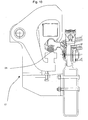
Figur 8 , in einer angehobenen Stellung, die auf die Anwesenheit von Schnee oder eines anderen Hindernisses zurückzuführen ist, und - Figur 10
- eine Ansicht wie
Figur 8 und9 , jedoch in einer Stellung höchsten Ausschlages des Seils gegenüber der Klemme. - In
Figur 1 ist mit der Bezugsziffer 1 insgesamt eine Seilbahnanlage im Bereich des Ausgangs einer Station angegeben. - Die Anlage umfasst auf bekannte Art und Weise ein Trag-/Zugseil 2, eine Vielzahl von Rollen 3 am Ausgang der Station, die einer Kuppelschiene bekannter und nicht gezeigter Art gegenüberliegen, eine Klemme 4, an der das nicht gezeigte Fahrbetriebsmittel aufgehängt ist, und mindestens eine das Seil 2 tragende Rolle 5 mit angekoppelter Klemme 4 und eine tragende oder niederhaltende Rollenbatterie 6 gemäß dem Verlauf des Seils 2.
- Wie in
Figur 7 dargestellt, ist die Rollenbatterie 6 mit einem oberen, äußeren Seilfangschuh 7 und mit einem inneren, oberen Schutz 8 versehen, wenn die Stütze der Rollenbatterie 6 als Niederhaltestütze wirkt, bei der das Seil von unten auf die Rollenbatterie drückt. Die Rollenbatterie 6 ist hingegen mit einem unteren, äußeren Seilfangschuh 9 und mit einem unteren, inneren Schutz 10 versehen, wenn die Stütze der Rollenbatterie 6 als Tragstütze wirkt, bei der das Seil von oben auf die Rollenbatterie 6 drückt. Mit der beschriebenen Situation könnte eine Entgleisung an der Rollenbatterie 6 schon eine übermäßige Ablenkung des Seils im Kupplungsbereich verursachen, in welchem die Klemme 4 noch nicht imstande ist das Seil 2 zu ergreifen, da die Öffnung ihres Mauls nicht fähig ist, das Seil zu ergreifen, mit der daraus folgenden Gefahr, dass das Seilbetriebmittel abstürzt. - Gemäß der Erfindung ist vor dem Kupplungsbereich der Klemme 4 am Seil 2, vor der Kupplungsschiene, eine Ausrichtvorrichtung 11 vorgesehen, die fähig ist, die auf eine Entgleisung an der Rollenbatterie 6 zurückzuführende Ablenkung des Seils 2 derart zu begrenzen, dass das Seil 2 sich immer innerhalb der Maulöffnung 12 der Klemme befindet. Wie in
Figur 2 gezeigt, ist die Ausrichtvorrichtung 11 durch eine Halterung 13 gebildet, in der eine Bohrung 14 ausgenommen ist, mit größeren Abmessungen als der Durchmesser des Seils 2, die vom Abstand von der vorgesehenen Klemmstellung abhängen. - Gemäß einer Ausführungsform ist der Ausrichtvorrichtung 11 mindestens eine Seilfanghalterung 15 zur Auflage des Seils 2 zugeordnet, an dem schon die Klemme 4 gekoppelt ist. Die Seilfanghalterung 15 weist eine konkave Oberfläche auf, um das Seil 2 in Richtung der Mitte der Konkavität zu richten.
- In einer anderen Ausführungsform ist zusätzlich zur ersten oder allein mindestens einer der das Seil 2 tragenden Rollen 3 mit angekoppelten Klemme 4 ein oberer Seilfangbügel 16 zugeordnet, der das Seil 2 oben in seiner Ablenkung begrenzt.
- Zweckmäßiger Weise ist der Ausrichtvorrichtung 11 eine Meldeanlage zugeordnet, die die Seilbahnanlage anhält, sobald das Seil 2 die Bohrung 14 berührt, wobei gleichwohl ein Anhängen der Klemme erlaubt wird, wobei jedoch die Seilbahnanlage mit schon angehängter Klemme angehalten wird, und daher ohne Gefahr, dass das Fahrbetriebsmittel zusammen mit den Passagieren herabfällt.
- In der in
Figur 8 ,9 und10 dargestellten Variante ist anstelle einer Halterung 15 eine Zwangsführungseinrichtung 17 vorgesehen. Diese ist an einem Tragaufbau 18 der Kupplungsschiene 19 der Tragrolle 20 der Klemme 2 angebracht. - Die Zwangsführungsvorrichtung 17 ist über eine Konsole 21 angebracht, die mittels Schraubbolzen 22 am Tragaufbau 18 befestigt ist. Von der Konsole 21 erstreckt sich ein Stützbock 23 nach oben, an dem über eine Anlenkung 24 eine Gabel 25 befestigt ist. Diese weist einen unteren Arm 26 auf, dessen freies Ende als Auflage 27 für das Seil 2 ausgebildet ist. Die Gabel 25 weist überdies einen oberen Arm 28 auf, der mit einem Ansatz 29 endet, um mit dem Körper der Klemme 2 in Berührung zu kommen.
- Zwischen der Auflage 27 und dem Ansatz 29 ist ein einstellbarer Abstand 30 festgelegt, der die Gesamtheit der Klemme 4 und des Seils 2 mit oberhalb der Auflage 27 frei passierendem Seil 2 bei einer Anklemmung passieren zu lassen, die normal zwischen Klemme und Seil erfolgt ist. In Anwesenheit einer Schneeanhäufung 33 (
Figur 9 ) wird die Klemme angehoben und mit derselben die Gabel 25, wobei das Seil 2 an der Auflage 27 derart angehoben wird, dass die Klemme 4 noch das Seil umgreift. InFigur 10 ist hingegen der Höchstausschlag 31 nach unten eingezeichnet, wenn die Gabel 25 an der Auflage 27 anschlägt, wobei klar wird, dass so die Klemme auf eine vollständige Anklemmung des Seils ausgerichtet ist.
Claims (9)
- Seilentgleisungsschutzvorrichtung für Trag-/Zugseile von Seilbahnanlagen in einer Anlage (1), umfassend ein Trag-/Zugseil (2), eine Vielzahl von eine Kupplungsschiene flankierenden Rollen (3) am Ausgang der Station, eine Vielzahl von Klemmen (4), an denen die Fahrbetriebsmittel aufgehängt sind, und mindestens eine das Seil (2) tragende Rolle (5) mit angekoppelter Klemme (4) und eine Trag- oder Niederhalterrollenbatterie (6) je nach der Seilführung (2), wobei die Kupplungsschiene einen Kupplungsbereich zwischen Seil (2) und Klemmen (4) bildet, dadurch gekennzeichnet, dass vor dem Kupplungsbereich der Klemmen (4) am Seil (2), vor der Kupplungsschiene eine Ausrichtvorrichtung (11) angeordnet ist, die die auf eine Entgleisung an der Rollenbatterie (6) zurückzuführende Ablenkung des Seils (2) derart begrenzt, dass das Seil (2) sich immer innerhalb der Maulöffnung (12) der Klemme (4) befindet.
- Seilentgleisungsschutzvorrichtung nach Anspruch 1, dadurch gekennzeichnet, dass die Ausrichtvorrichtung (11) durch eine Halterung (13) gebildet ist, in der eine Bohrung (14) mit Abmessungen ausgenommen ist, die größer als der Durchmesser des Seils (2) sind, und vom Abstand von der vorgesehenen Anklemmstelle abhängen.
- Seilentgleisungsschutzvorrichtung nach Anspruch 1, dadurch gekennzeichnet, dass der Ausrichtvorrichtung (11) mindestens eine Seilfanghalterung (15) zur Auflage für das Seil (2) zugeordnet ist, an dem die Klemme (4) schon angekoppelt ist.
- Seilentgleisungsschutzvorrichtung nach Anspruch 3, dadurch gekennzeichnet, dass die Seilfanghalterung (15) eine konkave Oberfläche aufweist, die das Seil (2) in Richtung der Mitte der Konkavität richtet.
- Seilentgleisungsschutzvorrichtung nach Anspruch 3, dadurch gekennzeichnet, dass zusätzlich zur Halterung (15) oder allein mindestens einer der das Seil (2) tragenden Rollen (3) mit angekoppelter Klemme (4) mindestens ein oberer Seilfangbügel (16) zugeordnet ist, der das Seil (2) oben in seiner Ablenkung begrenzt.
- Seilentgleisungsschutzvorrichtung nach den vorstehenden Ansprüchen, dadurch gekennzeichnet, dass Ausrichtvorrichtung (11) eine Meldeanlage zugeordnet ist, die die Seilbahnanlage anhält, sobald das Seil (2) in der Ausrichtvorrichtung (11) gezwungen wird, wobei ein Anhängen der Klemme erlaubt wird, indem jedoch die Seilbahnanlage mit schon angehängter Klemme angehalten wird, und daher ohne Gefahr, dass das Förderbetriebsmittel zusammen mit den Passagieren herabfällt.
- Seilentgleisungsschutzvorrichtung nach den vorstehenden Ansprüchen, dadurch gekennzeichnet, dass sie überdies anstelle oder zusätzlich zur Halterung (15) eine Zwangsführungseinrichtung (17) umfasst, die ihrerseits eine Gabel (25) umfasst, die am Tragaufbau der Kupplungsschiene über eine Konsole angelenkt ist und einen oberen Arm (26), dessen freies Ende als Auflage (27) für das Seil (2) ausgebildet ist, und einen oberen Arm aufweist, mit einem freien Ende (29), das mit dem Körper der Klemme in Berührung kommt, wobei zwischen der Auflage (27) und dem freien Ende (29) ein einstellbarer Abstand (30) festgelegt ist, um die Gesamtheit der Klemme (4) und des Seils (2) mit frei oberhalb der Auflage (27) passierendem Seil (2) bei normal erfolgter Anklemmung zwischen Klemme und Seil passieren zu lassen, wobei die Gabel (25) in der Drehung durch einen Anschlag (32) begrenzt ist, der gegen den unteren Arm zum Anschlagen kommt und bei beispielsweise auf eine Schneeanhäufung an der Kupplungsschiene zurückzuführende Anhebung der Klemme anhebbar ist.
- Seilentgleisungsschutzvorrichtung nach Anspruch 7, dadurch gekennzeichnet, dass der Anschlag (32) einstellbar ist.
- Seilentgleisungsschutzvorrichtung nach den vorstehenden Ansprüchen, dadurch gekennzeichnet, dass die untere und die obere Halterung und/oder die Führung aus Rollen bestehen, die angemessen ausgebildet und positioniert sind, um das Seil (2) zu führen.
Applications Claiming Priority (2)
| Application Number | Priority Date | Filing Date | Title |
|---|---|---|---|
| IT000051A ITBZ20050051A1 (it) | 2005-09-29 | 2005-09-29 | Dispositivo antiscarrucolamento per funi di impianti funiviari. |
| PCT/IB2006/002512 WO2007036776A1 (de) | 2005-09-29 | 2006-09-13 | Seilentgleisungsschutzvorrichtung für trag-/zugseile von seilbahnanlagen |
Publications (2)
| Publication Number | Publication Date |
|---|---|
| EP1928721A1 EP1928721A1 (de) | 2008-06-11 |
| EP1928721B1 true EP1928721B1 (de) | 2010-06-09 |
Family
ID=37591877
Family Applications (1)
| Application Number | Title | Priority Date | Filing Date |
|---|---|---|---|
| EP06795475A Active EP1928721B1 (de) | 2005-09-29 | 2006-09-13 | Seilentgleisungsschutzvorrichtung für trag-/zugseile von seilbahnanlagen |
Country Status (8)
| Country | Link |
|---|---|
| US (1) | US7891300B2 (de) |
| EP (1) | EP1928721B1 (de) |
| CN (1) | CN101351371B (de) |
| AT (1) | ATE470611T1 (de) |
| DE (1) | DE502006007190D1 (de) |
| ES (1) | ES2347279T3 (de) |
| IT (1) | ITBZ20050051A1 (de) |
| WO (1) | WO2007036776A1 (de) |
Cited By (1)
| Publication number | Priority date | Publication date | Assignee | Title |
|---|---|---|---|---|
| CN102910176A (zh) * | 2011-08-02 | 2013-02-06 | 盐城海旭数控装备有限公司 | 悬挂式新能源轨道公交车用悬挂装置 |
Families Citing this family (12)
| Publication number | Priority date | Publication date | Assignee | Title |
|---|---|---|---|---|
| ITBZ20030005A1 (it) * | 2003-01-30 | 2004-07-31 | High Technology Invest Bv | Dispositivo pressore per la conduzione di fune in sistemi di trasporto a trazione di fune. |
| ITBZ20050051A1 (it) | 2005-09-29 | 2007-03-30 | High Technology Invest Bv | Dispositivo antiscarrucolamento per funi di impianti funiviari. |
| ITMI20070835A1 (it) * | 2007-04-20 | 2008-10-21 | Rolic Invest Sarl | Impianto di trasporto a fune e metodo di azionamento dello stesso |
| ITMI20070157U1 (it) * | 2007-04-20 | 2008-10-21 | Rolic Invest Sarl | Seggiovia |
| ITMI20071618A1 (it) * | 2007-08-03 | 2009-02-04 | Rolic Invest Sarl | Impianto di trasporto a fune e metodo di azionamento dello stesso |
| ITMI20072071A1 (it) * | 2007-10-26 | 2009-04-27 | Rolic Invest Sarl | Impianto di trasporto a fune e metodo di azionamento dello stesso |
| IT1395098B1 (it) | 2009-07-09 | 2012-09-05 | Rolic Invest Sarl | Unita' di trasporto per impianti di trasporto a fune |
| IT1395737B1 (it) * | 2009-08-04 | 2012-10-19 | Rolic Invest Sarl | Dispostivo di richiamo di un sedile per skilift |
| IT1401120B1 (it) | 2010-07-14 | 2013-07-12 | Rolic Invest Sarl | Scambio per impianto di trasporto a fune e impianto di trasporto a fune comprendente tale scambio. |
| AT12625U1 (de) * | 2010-10-18 | 2012-09-15 | Innova Patent Gmbh | Seilbahnanlage |
| BR112015001783B1 (pt) | 2012-07-27 | 2022-04-05 | Eskom Holdings Soc Limited | Aparelho para uso em um cabo e sistema e método de inspeção de um cabo |
| FR3069512B1 (fr) * | 2017-07-27 | 2019-08-23 | Vinci Construction | Installation de transport a cable ou analogue, et vehicule adapte a une telle installation |
Family Cites Families (94)
| Publication number | Priority date | Publication date | Assignee | Title |
|---|---|---|---|---|
| US472211A (en) | 1892-04-05 | Half to louis a | ||
| DE423865C (de) | 1925-02-28 | 1926-01-12 | Karl Laissle Dipl Ing | Seiltragevorrichtung |
| US1944446A (en) | 1932-05-27 | 1934-01-23 | Mckay Co | Swing |
| FR891743A (fr) | 1941-11-25 | 1944-03-17 | Pohlig J Ag | Commande pour téléfériques |
| FR913146A (fr) | 1945-08-06 | 1946-08-29 | Téléphérique à bennes multiples, à marche continue, pour voyageurs | |
| CH259291A (de) | 1947-02-21 | 1949-01-15 | Eisen Und Stahlwerke Oehler & | Sicherheitseinrichtung an Schwebebahnanlagen. |
| US2662587A (en) | 1949-11-18 | 1953-12-15 | Mcilvaine Alexander | Chair for aerial skilifts |
| FR1100001A (fr) | 1954-02-19 | 1955-09-15 | Perfectionnements aux transporteurs aériens | |
| US2710650A (en) | 1954-03-19 | 1955-06-14 | Riblet Tramway Company | Aerial ski lift chair |
| US2985224A (en) | 1958-03-28 | 1961-05-23 | Riblet Tramway Company | Aerial lift passenger chair |
| FR1199721A (fr) | 1958-06-20 | 1959-12-16 | Perfectionnements aux transporteurs aériens à câble | |
| CH360704A (fr) | 1960-03-15 | 1962-03-15 | Mayor Henry | Dispositif de sécurité pour un câble de transporteurs aériens |
| US3170412A (en) | 1963-05-06 | 1965-02-23 | Ribiet Tramway Company | Chair swing damper |
| FR1423648A (fr) | 1963-05-10 | 1966-01-07 | Doppelmayr & Sohn | Dispositif de sécurité pour téléphériques, notamment pour téléphériques monocâbles |
| GB1326264A (en) | 1969-10-29 | 1973-08-08 | Krampe Co Fertigund In Bergbau | Railway track and vehicles for use in underground mining |
| DE2020746C3 (de) | 1970-04-28 | 1979-03-08 | Fritz 6685 Schiffweiler Leh | Seilführungsstation für schienengebundene Flurförderwagen |
| AT315910B (de) | 1970-08-21 | 1974-06-25 | Waagner Biro Ag | Zugseilschwingungsdämpfer |
| DE2101743A1 (de) | 1971-01-15 | 1972-09-07 | Maschinenfabrik Scharf Gmbh, 4700 Hamm | Rollenbock mit einer gesteuerten Zwangsführung für das Zugseil einer insbesondere in Förderstrecken des Bergbaus verlegten Seilbahn |
| CH554761A (de) | 1972-11-03 | 1974-10-15 | Streiff Mathias | Vorrichtung zum befestigen von zugseiltragrollen, fahrund/oder fuehrungsschienen und treppen an rampe von standseilbahnen. |
| CH563902A5 (de) | 1973-11-20 | 1975-07-15 | Habegger Willy | |
| GB1460106A (en) | 1974-05-22 | 1976-12-31 | Coal Industry Patents Ltd | Method of propulsion of vehicles |
| FR2340895A1 (fr) | 1976-02-12 | 1977-09-09 | Pomagalski Sa | Dispositif de support et de guidage d'un cable aerien |
| AT342655B (de) | 1976-06-14 | 1978-04-10 | Waagner Biro Ag | Zugseilschwingungsdampfer fur seilforderanlagen |
| JPS5810264B2 (ja) | 1976-08-31 | 1983-02-24 | 日産自動車株式会社 | 架空索道システムにおける車両の走行安定機構 |
| FR2387830A1 (fr) | 1977-04-22 | 1978-11-17 | Pomagalski Sa | Dispositif de securite surveillant l'integrite des elements d'appui du cable d'un balancier d'une telecabine ou d'un telesiege |
| FR2416148A1 (fr) | 1978-02-01 | 1979-08-31 | Pomagalski Sa | Dispositif de securite pour un balancier de support d'un cable aerien d'une installation de transport |
| FR2392858A1 (fr) | 1977-05-12 | 1978-12-29 | Mautino Victor | Ensemble support a galets pour cable d'installation de transport aerien par monocable porteur-tracteur |
| FR2391450A1 (fr) | 1977-05-18 | 1978-12-15 | Stgm | Procede et dispositif de controle de position d'un cable par rapport a un guide roulant |
| US4470355A (en) | 1977-11-14 | 1984-09-11 | Kunczynski Jan K | Pneumatic cable tensioning apparatus and method for an aerial tramway or the like |
| DE2811336A1 (de) | 1978-03-16 | 1979-09-20 | Scharf Gmbh Maschf | Zugseilbetriebene transportbahn |
| US4226187A (en) | 1978-10-23 | 1980-10-07 | Sdi Welding Corporation | Ski lift apparatus and safety device |
| JPS5599456A (en) | 1979-01-25 | 1980-07-29 | Nissan Motor | Suspension mechanism of aerial track car |
| FR2496579A1 (fr) | 1980-12-22 | 1982-06-25 | Pomagalski Sa | Telepherique bicable |
| DE3109294A1 (de) | 1981-03-11 | 1982-10-14 | Muckenhaupt GmbH, 4320 Hattingen | Seilgezogene transportbahn fuer den untertaegigen grubenbetrieb |
| DE3109944C2 (de) | 1981-03-14 | 1984-02-02 | PHB Weserhütte AG, 5000 Köln | Kuppelbare Umlauf-Drahtseilbahn zur Beförderung von Material, wie Schüttgut |
| AT373832B (de) | 1981-04-21 | 1984-02-27 | Nejez Josef Dipl Ing Dr Techn | Sicherheitseinrichtung fuer die ueberwachung der seillage von geerdeten foerderseilen auf rollenbatterien von seilbahnen und schleppliften |
| US4462314A (en) | 1982-02-05 | 1984-07-31 | Kunczynski Jan K | Rocker arm assembly for an aerial tramway |
| CH656357A5 (fr) | 1983-07-04 | 1986-06-30 | Vevey Atel Const Mec | Vehicule motorise suspendu. |
| IT8322994U1 (it) | 1983-09-16 | 1985-03-16 | Leitner Spa | Freno centrifugo per dispositivo di traino ad azione progressiva per sciovie. |
| FR2562857B1 (fr) | 1984-04-13 | 1987-01-16 | Pomagalski Sa | Balanciers d'une installation de transport a cable aerien |
| AT385480B (de) | 1985-09-11 | 1988-04-11 | Doppelmayr & Sohn | Laufwerkstraeger fuer seilbahnen, insbesondere fuer einseil-umlaufbahnen |
| US4671187A (en) | 1985-09-20 | 1987-06-09 | Kunczynski Jan K | Deropement sensor apparatus with gravity-biased, falling, magnetic member |
| IT206251Z2 (it) | 1985-10-09 | 1987-07-13 | Leitner Spa | Guida di invito ammortizzato per veicoli funiviari. |
| FR2604675B1 (fr) | 1986-10-02 | 1988-12-30 | Pomagalski Sa | Installation de transport aerien a deux cables porteurs-tracteurs a poulies decalees |
| IT1207747B (it) | 1987-03-06 | 1989-06-01 | Lettner S P A | Impianto teleferico con deviazione del persorso della fune traente. |
| FR2612144B1 (fr) | 1987-03-11 | 1991-09-06 | Pomagalski Sa | Installation de transport aerien a deux cables porteurs-tracteurs a poulies decalees verticalement |
| DE3834116A1 (de) | 1987-11-04 | 1989-05-24 | Scharf Gmbh Maschf | Anordnung zur fuehrung eines zugseils |
| AT388146B (de) * | 1988-01-08 | 1989-05-10 | Engel Edwin Dipl Ing Dr Techn | Verfahren und vorrichtungen zur selbsttaetigen ueberwachung der lage der foerderseile von seilbahnen und schleppliften auf einer seiltragrolle |
| AT390926B (de) | 1989-03-14 | 1990-07-25 | Swoboda Seilbahnbau Gmbh | Vorrichtung zum ueberwachen der lage eines foerderseiles einer seilbahn oder eines schleppliftes auf einer seilrolle |
| FR2644740A1 (fr) * | 1989-03-22 | 1990-09-28 | Mareau Dominique | Dispositif antiderailleur de cable pour pylone de telepherique mono-cable |
| DE3927757C1 (en) | 1989-08-23 | 1991-03-28 | Kloeckner-Becorit Gmbh, 4620 Castrop-Rauxel, De | Wagon rope haulage system - uses single flange rollers on spring-loaded levers |
| AT393479B (de) | 1990-03-08 | 1991-10-25 | Waagner Biro Ag | Verbindung von seilbahnwagen |
| FR2670451A1 (fr) | 1990-12-18 | 1992-06-19 | Pomagalski Sa | Telecabine ou telesiege debrayage a deux boucles de cable. |
| FR2670452A1 (fr) | 1990-12-18 | 1992-06-19 | Pomagalski Sa | Dispositif amortisseur des oscillations du cable tracteur d'un telepherique. |
| US5113768A (en) | 1991-03-15 | 1992-05-19 | Brown Garrett W | Cable-suspended apparatus for supporting a stabilized camera assembly |
| FR2676981B1 (fr) * | 1991-06-03 | 1993-08-27 | Pomagalski Sa | Dispositif de securite d'une installation de transport a cable aerien. |
| DE4127373A1 (de) | 1991-08-19 | 1993-02-25 | Wolf Von Bodisco | Schwebebahn an einer schiene haengend |
| WO1993011015A1 (fr) | 1991-11-29 | 1993-06-10 | Seiko Epson Corporation | Deplacement dans un appareil de transfert et controleur d'entrainement de l'element de transfert |
| FR2706404A1 (fr) | 1993-06-09 | 1994-12-23 | Montagner Rene | Installation de téléski. |
| FR2709278B1 (fr) | 1993-08-25 | 1995-10-27 | Pomagalski Sa | Dispositif de stabilisation des pinces d'un téléporteur. |
| CA2143504A1 (en) | 1994-03-11 | 1995-09-12 | Ernst Egli | Rope guide system for an aerial ropeway, particularly a circuital aerial ropeway |
| FR2719011B1 (fr) | 1994-04-22 | 1996-07-12 | Pomagalski Sa | Installation de transport à câble tracteur et à moteur embarqué. |
| IT1270233B (it) | 1994-06-16 | 1997-04-29 | Leitner Spa | Morsa del tipo a doppia azione per il vincolo alla fune traente di un veicolo funicolare |
| IT1270234B (it) | 1994-06-16 | 1997-04-29 | Leitner Spa | Impianto funicolare a rotaia e fune traente, in particolare per il trasporto urbano, del tipo in cui i veicoli sono dotati di morsa a ganasce mobili per l'agganciamento/sganciamento da detta fune traente |
| IT1276268B1 (it) | 1994-07-14 | 1997-10-28 | Hoelzl Costruzione Funivie Srl | Sistema di movimentazione per impianti funiviari a due o rispettivamente una via di corsa e presentante funi portanti o funi |
| AT403147B (de) * | 1995-05-29 | 1997-11-25 | Girak Garaventa Gmbh | Mechanischer seilentgleisungsschutz |
| WO1999028716A1 (en) | 1997-11-26 | 1999-06-10 | Litens Automotive Partnership | Load sensor |
| EP0970864B1 (de) | 1998-07-09 | 2003-12-03 | Ropetrans AG | Haltevorrichtung für ein Tragseil |
| US6036282A (en) | 1998-07-31 | 2000-03-14 | Zeftron, Inc. | Railcar air motor driven generator |
| IT1313108B1 (it) | 1999-08-18 | 2002-06-17 | Leitner Spa | Morsa a ganasce mobili perfezionata per l'aggancio e lo sgancio diveicoli ad una fune traente di un impianto di trasporto |
| IT1310249B1 (it) | 1999-09-24 | 2002-02-11 | Leitner Spa | Rulliera a doppio effetto per sostegni d'impianti a monofune, inparticolare seggiovie e cabinovie. |
| IT1313913B1 (it) | 1999-10-01 | 2002-09-26 | Leitner Spa | Impianto di trasporto urbano a guida vincolata. |
| IT1316116B1 (it) | 2000-01-21 | 2003-03-28 | Leitner Spa | Dispositivo per la impostazione e regolazione automatica della forzadi trazione di una fune di un verricello sopratesta per una macchina |
| AT409253B (de) | 2000-07-20 | 2002-07-25 | Innova Patent Gmbh | Anlage zur beförderung von personen und verfahren zum betrieb einer derartigen anlage |
| US20020043829A1 (en) | 2000-10-04 | 2002-04-18 | Garaventa Holding Ag | Method and arrangement to close a bubble top for a chairlift |
| IT1316148B1 (it) | 2000-11-27 | 2003-03-28 | High Technology Invest Bv | Dispositivo di controrullo per impianti di trasporto a fune ditrazione. |
| IT1316149B1 (it) | 2000-11-27 | 2003-03-28 | High Technology Invest Bv | Impianto di trasporto a trazione di fune mossa continua con veicolidotati di morse di agganciamento disimpegnabile. |
| FR2823482A1 (fr) | 2001-04-11 | 2002-10-18 | Pomagalski Sa | Dispositif de support et de guidage pour cable de systeme de transport |
| AT411523B (de) | 2002-01-24 | 2004-02-25 | Innova Patent Gmbh | Sessel für eine seilbahnanlage |
| EP1364853A1 (de) | 2002-05-22 | 2003-11-26 | Pomagalski S.A. | Stütz- und Führungsvorrichtung für das Seil eines Transportsystems |
| EP1419950A1 (de) | 2002-11-14 | 2004-05-19 | Innova Patent GmbH | Seilbahnanlage mit verdrehbaren Kabinen oder Sesseln |
| ITBZ20030005A1 (it) | 2003-01-30 | 2004-07-31 | High Technology Invest Bv | Dispositivo pressore per la conduzione di fune in sistemi di trasporto a trazione di fune. |
| AT411983B (de) | 2003-03-26 | 2004-08-26 | Edwin Dipl Ing Dr Techn Engel | Beweglicher seilfangschuh |
| ITBZ20030050A1 (it) | 2003-10-03 | 2005-04-04 | High Technology Invest Bv | Smorzatore per funi traenti di funivie. |
| FR2867142B1 (fr) | 2004-03-08 | 2010-09-17 | Pomagalski Sa | Dispositif d'appui et de guidage d'un cable aerien porteur- tracteur au moyen d'un balancier a liaison d'accouplement elastique, et installation de remontee mecanique du type telesiege ou telecabine comportant un tel dispositif |
| CN2707588Y (zh) * | 2004-04-01 | 2005-07-06 | 肖公平 | 摘挂型自锁式活动抱索器 |
| ITMI20050800A1 (it) | 2005-05-03 | 2006-11-04 | Ferruccio Levi | Sistema di movimentazione per impianto funiviario comprendente due funi traenri |
| ITBZ20050051A1 (it) | 2005-09-29 | 2007-03-30 | High Technology Invest Bv | Dispositivo antiscarrucolamento per funi di impianti funiviari. |
| ITBZ20060036A1 (it) | 2006-08-16 | 2008-02-17 | High Technology Investments Bv | Dispositivo anticaduta per seggiole di seggiovie con dispositivo di comando d'impegno e disimpegno dello sbarramento. |
| ITMI20070157U1 (it) | 2007-04-20 | 2008-10-21 | Rolic Invest Sarl | Seggiovia |
| ITMI20070835A1 (it) | 2007-04-20 | 2008-10-21 | Rolic Invest Sarl | Impianto di trasporto a fune e metodo di azionamento dello stesso |
| US7410068B1 (en) | 2007-07-06 | 2008-08-12 | Agudio S.P.A. | Blondin cableway installation |
| ITMI20071618A1 (it) | 2007-08-03 | 2009-02-04 | Rolic Invest Sarl | Impianto di trasporto a fune e metodo di azionamento dello stesso |
| EP2075172A1 (de) | 2007-12-28 | 2009-07-01 | Rolic Invest Sarl | Seilbahnsystem mit Tragkabeln und einem getrennten Zugkabel |
-
2005
- 2005-09-29 IT IT000051A patent/ITBZ20050051A1/it unknown
-
2006
- 2006-09-13 US US12/088,540 patent/US7891300B2/en active Active
- 2006-09-13 DE DE502006007190T patent/DE502006007190D1/de active Active
- 2006-09-13 CN CN2006800437040A patent/CN101351371B/zh active Active
- 2006-09-13 EP EP06795475A patent/EP1928721B1/de active Active
- 2006-09-13 ES ES06795475T patent/ES2347279T3/es active Active
- 2006-09-13 AT AT06795475T patent/ATE470611T1/de active
- 2006-09-13 WO PCT/IB2006/002512 patent/WO2007036776A1/de not_active Ceased
Cited By (1)
| Publication number | Priority date | Publication date | Assignee | Title |
|---|---|---|---|---|
| CN102910176A (zh) * | 2011-08-02 | 2013-02-06 | 盐城海旭数控装备有限公司 | 悬挂式新能源轨道公交车用悬挂装置 |
Also Published As
| Publication number | Publication date |
|---|---|
| WO2007036776A1 (de) | 2007-04-05 |
| ES2347279T3 (es) | 2010-10-27 |
| ATE470611T1 (de) | 2010-06-15 |
| CN101351371A (zh) | 2009-01-21 |
| DE502006007190D1 (de) | 2010-07-22 |
| EP1928721A1 (de) | 2008-06-11 |
| CN101351371B (zh) | 2011-01-12 |
| ITBZ20050051A1 (it) | 2007-03-30 |
| US7891300B2 (en) | 2011-02-22 |
| US20090165666A1 (en) | 2009-07-02 |
Similar Documents
| Publication | Publication Date | Title |
|---|---|---|
| EP1928721B1 (de) | Seilentgleisungsschutzvorrichtung für trag-/zugseile von seilbahnanlagen | |
| DE3543464C2 (de) | ||
| EP1209056B1 (de) | Seilzugförderanlage mit stetig bewegtem Seil und Fahrzeugen, versehen mit lösbaren Ankuppelklemmen | |
| EP1587724B1 (de) | Niederhaltevorrichtung für die seilführung in seilgezogenen transportsystemen | |
| EP2412596A1 (de) | Seilbahnanlage und Verfahren zu deren Betrieb | |
| EP0150701B1 (de) | Kuppelklemme | |
| EP0509139A1 (de) | Vorrichtung zur Halterung und Führung einer Achse oder Welle oder eines Lagerrings | |
| EP0004328A1 (de) | Seilsicherungsklemme | |
| EP2556935A2 (de) | Betonmischanlage | |
| DE2020746B2 (de) | Seilführungsstation für schienengebundene Flurförderwagen | |
| DE3713264A1 (de) | Vorrichtung zum transport von spinnkannen mit einem umlaufenden foerderelement | |
| EP2127990B1 (de) | Vorrichtung zum Erkennen einer Fehllage eines Tragseils einer Seilbahn | |
| EP1227022A2 (de) | Seilbahn | |
| EP0327882A2 (de) | Seilförderanlage | |
| AT409254B (de) | Laufrolle für das fahrwerk des fahrbetriebsmittels einer seilbahnanlage | |
| EP0359162A2 (de) | Schleppvorrichtung für Fahrzeugräder in Autowaschanlagen | |
| AT346029B (de) | Seilfuehrungsvorrichtung fuer seilwinden | |
| DE2115883A1 (de) | Sicherheitsbremse für Personen-Förderanlagen | |
| EP0358932A2 (de) | Schleppvorrichtung für Fahrzeugräder in Autowaschanlagen | |
| DE2948045C2 (de) | Kupplungsstück | |
| DE4036036A1 (de) | Fangvorrichtung eines aufzuges | |
| DE2826772C2 (de) | Seilauffangvorrichtung für eine Tragrolle eines Skiliftes mit Schleppbügelklemmen | |
| EP0644095A1 (de) | Kuppelbare Seilklemme | |
| DE2936990A1 (de) | Greifvorrichtung fuer rohre | |
| DE3026860C2 (de) | Vorrichtung zur Fallsicherung von Hubelementen |
Legal Events
| Date | Code | Title | Description |
|---|---|---|---|
| PUAI | Public reference made under article 153(3) epc to a published international application that has entered the european phase |
Free format text: ORIGINAL CODE: 0009012 |
|
| 17P | Request for examination filed |
Effective date: 20080331 |
|
| AK | Designated contracting states |
Kind code of ref document: A1 Designated state(s): AT CH DE ES FR IT LI |
|
| DAX | Request for extension of the european patent (deleted) | ||
| RBV | Designated contracting states (corrected) |
Designated state(s): AT CH DE ES FR IT LI |
|
| GRAP | Despatch of communication of intention to grant a patent |
Free format text: ORIGINAL CODE: EPIDOSNIGR1 |
|
| GRAS | Grant fee paid |
Free format text: ORIGINAL CODE: EPIDOSNIGR3 |
|
| GRAA | (expected) grant |
Free format text: ORIGINAL CODE: 0009210 |
|
| AK | Designated contracting states |
Kind code of ref document: B1 Designated state(s): AT CH DE ES FR IT LI |
|
| REG | Reference to a national code |
Ref country code: CH Ref legal event code: EP |
|
| REF | Corresponds to: |
Ref document number: 502006007190 Country of ref document: DE Date of ref document: 20100722 Kind code of ref document: P |
|
| REG | Reference to a national code |
Ref country code: CH Ref legal event code: NV Representative=s name: HEPP WENGER RYFFEL AG |
|
| REG | Reference to a national code |
Ref country code: ES Ref legal event code: FG2A Ref document number: 2347279 Country of ref document: ES Kind code of ref document: T3 |
|
| PLBI | Opposition filed |
Free format text: ORIGINAL CODE: 0009260 |
|
| PLAX | Notice of opposition and request to file observation + time limit sent |
Free format text: ORIGINAL CODE: EPIDOSNOBS2 |
|
| 26 | Opposition filed |
Opponent name: DOPPELMAYR SEILBAHNEN GMBH Effective date: 20110309 |
|
| REG | Reference to a national code |
Ref country code: DE Ref legal event code: R026 Ref document number: 502006007190 Country of ref document: DE Effective date: 20110309 |
|
| PLAF | Information modified related to communication of a notice of opposition and request to file observations + time limit |
Free format text: ORIGINAL CODE: EPIDOSCOBS2 |
|
| PLBB | Reply of patent proprietor to notice(s) of opposition received |
Free format text: ORIGINAL CODE: EPIDOSNOBS3 |
|
| PLAB | Opposition data, opponent's data or that of the opponent's representative modified |
Free format text: ORIGINAL CODE: 0009299OPPO |
|
| R26 | Opposition filed (corrected) |
Opponent name: DOPPELMAYR SEILBAHNEN GMBH Effective date: 20110309 |
|
| REG | Reference to a national code |
Ref country code: FR Ref legal event code: PLFP Year of fee payment: 11 |
|
| REG | Reference to a national code |
Ref country code: FR Ref legal event code: PLFP Year of fee payment: 12 |
|
| PLCK | Communication despatched that opposition was rejected |
Free format text: ORIGINAL CODE: EPIDOSNREJ1 |
|
| APBM | Appeal reference recorded |
Free format text: ORIGINAL CODE: EPIDOSNREFNO |
|
| APBP | Date of receipt of notice of appeal recorded |
Free format text: ORIGINAL CODE: EPIDOSNNOA2O |
|
| APAH | Appeal reference modified |
Free format text: ORIGINAL CODE: EPIDOSCREFNO |
|
| PLAB | Opposition data, opponent's data or that of the opponent's representative modified |
Free format text: ORIGINAL CODE: 0009299OPPO |
|
| REG | Reference to a national code |
Ref country code: DE Ref legal event code: R082 Ref document number: 502006007190 Country of ref document: DE Representative=s name: LORENZ SEIDLER GOSSEL RECHTSANWAELTE PATENTANW, DE Ref country code: DE Ref legal event code: R081 Ref document number: 502006007190 Country of ref document: DE Owner name: LEITNER S.P.A., VIPITENO, IT Free format text: FORMER OWNER: HIGH TECHNOLOGY INVESTMENTS B.V., LEIMUIDEN, NL |
|
| R26 | Opposition filed (corrected) |
Opponent name: DOPPELMAYR SEILBAHNEN GMBH Effective date: 20110309 |
|
| RAP2 | Party data changed (patent owner data changed or rights of a patent transferred) |
Owner name: LEITNER S.P.A. |
|
| REG | Reference to a national code |
Ref country code: CH Ref legal event code: PUE Owner name: LEITNER S.P.A., IT Free format text: FORMER OWNER: HIGH TECHNOLOGY INVESTMENTS B.V., NL |
|
| REG | Reference to a national code |
Ref country code: DE Ref legal event code: R100 Ref document number: 502006007190 Country of ref document: DE |
|
| APBU | Appeal procedure closed |
Free format text: ORIGINAL CODE: EPIDOSNNOA9O |
|
| PLBN | Opposition rejected |
Free format text: ORIGINAL CODE: 0009273 |
|
| STAA | Information on the status of an ep patent application or granted ep patent |
Free format text: STATUS: OPPOSITION REJECTED |
|
| REG | Reference to a national code |
Ref country code: AT Ref legal event code: PC Ref document number: 470611 Country of ref document: AT Kind code of ref document: T Owner name: LEITNER S.P.A., IT Effective date: 20180403 |
|
| 27O | Opposition rejected |
Effective date: 20180404 |
|
| REG | Reference to a national code |
Ref country code: FR Ref legal event code: TP Owner name: LEITNER S.P.A., IT Effective date: 20180531 |
|
| REG | Reference to a national code |
Ref country code: FR Ref legal event code: PLFP Year of fee payment: 13 |
|
| PGFP | Annual fee paid to national office [announced via postgrant information from national office to epo] |
Ref country code: DE Payment date: 20200928 Year of fee payment: 15 |
|
| REG | Reference to a national code |
Ref country code: DE Ref legal event code: R119 Ref document number: 502006007190 Country of ref document: DE |
|
| PG25 | Lapsed in a contracting state [announced via postgrant information from national office to epo] |
Ref country code: DE Free format text: LAPSE BECAUSE OF NON-PAYMENT OF DUE FEES Effective date: 20220401 |
|
| P01 | Opt-out of the competence of the unified patent court (upc) registered |
Effective date: 20230524 |
|
| PGFP | Annual fee paid to national office [announced via postgrant information from national office to epo] |
Ref country code: ES Payment date: 20231018 Year of fee payment: 18 |
|
| REG | Reference to a national code |
Ref country code: CH Ref legal event code: U11 Free format text: ST27 STATUS EVENT CODE: U-0-0-U10-U11 (AS PROVIDED BY THE NATIONAL OFFICE) Effective date: 20251001 |
|
| PGFP | Annual fee paid to national office [announced via postgrant information from national office to epo] |
Ref country code: IT Payment date: 20250903 Year of fee payment: 20 |
|
| PGFP | Annual fee paid to national office [announced via postgrant information from national office to epo] |
Ref country code: FR Payment date: 20250925 Year of fee payment: 20 Ref country code: AT Payment date: 20250917 Year of fee payment: 20 |
|
| REG | Reference to a national code |
Ref country code: ES Ref legal event code: FD2A Effective date: 20251030 |
|
| PGFP | Annual fee paid to national office [announced via postgrant information from national office to epo] |
Ref country code: CH Payment date: 20251001 Year of fee payment: 20 |
|
| PG25 | Lapsed in a contracting state [announced via postgrant information from national office to epo] |
Ref country code: ES Free format text: LAPSE BECAUSE OF NON-PAYMENT OF DUE FEES Effective date: 20240914 |